Festo VTSA-44-MP Series Manual
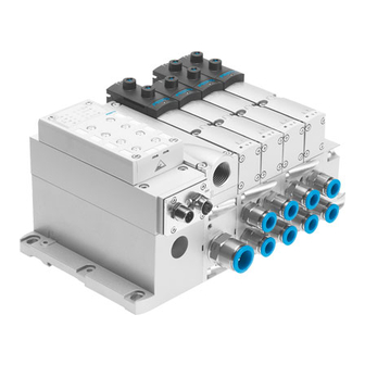
Valve terminal
Hide thumbs
Also See for VTSA-44-MP Series:
- Description (267 pages) ,
- Manual (176 pages) ,
- Description (208 pages)
Table of Contents
Advertisement
Quick Links
Advertisement
Chapters
Table of Contents

Related Manuals for Festo VTSA-44-MP Series


Summary of Contents for Festo VTSA-44-MP Series
- Page 1 Valve terminal VTSA/VTSA-F Manual VTSA... pneumatics Valve terminal with VTSA pneumatics Type VTSA-44-FB Type VTSA-44-MP... Type VTSA-44-ASI Type VTSA-FB-03E... Type VTSA-F-45-FB... Type VTSA-F-45-MP. Type VTSA-F-45-ASI Manual 538 923 en 1101f [751 096]...
- Page 3 ....... . . 538 923 E (Festo AG & Co. KG, D-73726 Esslingen, 2011) Internet: http://www.festo.com E-mail: service_international@festo.com...
- Page 4 Contents and general instructions ® CAGE CLAMP is a registered trademark of the respective owners in certain countries. Festo P.BE-VTSA-44-EN en 1101f...
-
Page 5: Table Of Contents
......1-37 Connection and display components of the electrical components ..1-40 Festo P.BE-VTSA-44-EN en 1101f... - Page 6 Address assignment of the valves ........3-44 Festo P.BE-VTSA-44-EN en 1101f...
- Page 7 ........5-23 Festo P.BE-VTSA-44-EN en 1101f...
- Page 8 ............Festo P.BE-VTSA-44-EN en 1101f...
-
Page 9: Intended Use
CE marking symbol. Standards and test values, which the product observes and fulfils, can be found in the section “Technical specifications”. The product-relevant EU directive can be found in the declaration of conformance. Festo P.BE-VTSA-44-EN en 1101f... -
Page 10: Target Group
– The technical data in this documentation may show values deviating from this. Target group This manual is directed exclusively toward technicians trained in control and automation technology. Service Please consult your local Festo repair service if you have any technical problems. VIII Festo P.BE-VTSA-44-EN en 1101f... -
Page 11: Notes On The Use Of This Manual
M23 round plug, M12 individual connections): Information about the electric/electronic components is included in the documentation supplied with the product. – Valve terminal with AS-interface: Information about the electric/electronic components is included in the documentation supplied with the product. Festo P.BE-VTSA-44-EN en 1101f... -
Page 12: Important User Instructions
This means that failure to observe this instruction may result in damage to property. The following pictogram marks passages in the text which describe activities with electrostatically sensitive compo- nents. Electrostatically sensitive components may be damaged if they are not handled correctly. Festo P.BE-VTSA-44-EN en 1101f... - Page 13 Accessories: Information on necessary or sensible accessories for the Festo product. Environment: Information on environment-friendly use of Festo products. Text markings The bullet indicates activities which may be carried out in • any order. 1. Figures denote activities which must be carried out in the numerical order specified.
- Page 14 – With two valve positions for 18 mm and 26 mm widths – With the widths 42 mm (ISO 1) and 52 mm (ISO 2) with a valve position – Per valve position with working lines (2) and (4). Festo P.BE-VTSA-44-EN en 1101f...
- Page 15 Vertical pressure shut-off – Plate on a valve location for isolating the valve pressure supply plate Vertical pressure supply – Plate on a valve position for individual compressed air supply plate Tab. 0/1: Product-specific terms and abbreviations XIII Festo P.BE-VTSA-44-EN en 1101f...
- Page 16 Contents and general instructions Festo P.BE-VTSA-44-EN en 1101f...
-
Page 17: Summary Of Components
Summary of components Chapter 1 Summary of components Festo P.BE-VTSA-44-EN en 1101f... -
Page 18: The Vtsa
......1-37 Connection and display components of the electrical components ..1-40 Festo P.BE-VTSA-44-EN en 1101f... -
Page 19: Summary Of Components
Information on the electronics of the VTSA... valve terminal with multi-pin node can be found in the corresponding package insert. Information on the electronics of the VTSA... valve terminal with AS interface can be found in the corresponding package insert. Festo P.BE-VTSA-44-EN en 1101f... -
Page 20: The Vtsa
1. Summary of components The VTSA... valve terminal Festo assists you in solving your automation tasks at machine level with VTSA... valve terminals. The modular structure of the valve terminal enables you to match it optimally in your machine or system. - Page 21 The maximum number of valve positions does not apply in the case of mixed components of a valve terminal with manifold sub-bases T1 and T2. Tab. 1/2: Number of valve positions for VTSA... with CPX terminal or FB 21, type 03 Festo P.BE-VTSA-44-EN en 1101f...
- Page 22 1, 2, 3 ... 4 The maximum number of valve positions does not apply in the case of mixed components of a valve terminal with manifold sub-bases T1 and T2. Tab. 1/4: Number of valve positions for VTSA... with AS-interface Festo P.BE-VTSA-44-EN en 1101f...
-
Page 23: Pneumatic Components (Width 18
The essential components of width 18 ... 52 mm showed Fig. 1/1 and Fig. 1/2. Right end plate 90° connection plate (optional) Pneumatic supply plates (optional) Manifold sub-base Fig. 1/1: Pneumatic base components of the VTSA... valve terminal (1. level) Festo P.BE-VTSA-44-EN en 1101f... - Page 24 Cover plate for valve position Vertical pressure shut-off plate (optional) (optional) Valves Vertical pressure supply plate (optional) Exhaust port cover Flow control plate (optional) Fig. 1/2: Pneumatic base components of the VTSA... valve terminal (2. level) Festo P.BE-VTSA-44-EN en 1101f...
-
Page 25: Main And Additional Supply
The pneumatic supply plate can also be used for additional supply. This is necessary, for example, if the valve terminal is operated with several pressure zones or if many valves simul- taneously are switched to flow or exhausted on the valve terminal. Festo P.BE-VTSA-44-EN en 1101f... -
Page 26: Valves
This valve can be used for vacuum operation with ejector pulse or for dual-pressure operation. See also the instructions in the Chapters 3.5 Pressure zone separation, 3.5.5 Vacuum/low pressure operation as well as in Appendix B1 Valve overview Tab. B/5. 1-10 Festo P.BE-VTSA-44-EN en 1101f... - Page 27 PNP or NPN output, individual connection plug type C 5/3-way valves: 5/3-way valve, normally open 5/3-way valve, normally exhausted 5/3-way valve, normally closed 1-11 Festo P.BE-VTSA-44-EN en 1101f...
- Page 28 14, the switching position 14 remains as is, since there is no spring return on control side 12. Switching position 12 is non-latching due to the mechanical spring force. Further information on the valves can be found in Appendix B. 1-12 Festo P.BE-VTSA-44-EN en 1101f...
-
Page 29: Manifold Sub-Bases
VABV-S4-...T2 or VABV-S2-...T1 VABV-S2-...T2 Identifier code on the type plate Black dot — of the manifold sub-base Colour of the solenoid coil Black contact Tab. 1/6: Identification of the manifold sub-bases, width 18 ... 52 mm 1-13 Festo P.BE-VTSA-44-EN en 1101f... -
Page 30: Pilot Control
You can ascertain the end plate with which your VTSA... valve terminal is fitted by means of the following table. Conversion between internal and external pilot air supply is described in Chapter 5.4.2. 1-14 Festo P.BE-VTSA-44-EN en 1101f... - Page 31 For notes on adjusting the pilot air selector or on fitting the end plates, see Chapter 3.4.2 Tab. 1/7: Variants of the right end plate for widths 18 ... 52 mm Note Instructions for combining the soft-start valve and the right end plate can be found in the VABV-S6-1Q-... assembly instructions. 1-15 Festo P.BE-VTSA-44-EN en 1101f...
-
Page 32: Pressure Zone Separation
A pressure zone separation of pilot ducts (12) and (14) is therefore not possible. You can ascertain the number of pressure zones with which your valve terminal is equipped by the marking on the sealing plate (see figure). 1-16 Festo P.BE-VTSA-44-EN en 1101f... -
Page 33: Vertical Stacking
You can fit further pneumatic components in each location between the manifold sub-base and the valve. This vertical stacking will enable you to implement certain additional effects as desired. Tab. 1/8 shows the basic design and possible components of vertical stacking. 1-17 Festo P.BE-VTSA-44-EN en 1101f... - Page 34 VABV...T1 or Working connections (2) and (4) type VABV...T2 turned 90°. For notes on installing the vertical stacking components, see Chapter 3 Tab. 1/8: Components of the pneumatic module of the VTSA... valve terminal 1-18 Festo P.BE-VTSA-44-EN en 1101f...
- Page 35 P-pressure regulator and the code 10 that the control range of this pressure regulator goes up to 10 bar. In the sales documentation and in the Festo Configurator, the components are marked with an ID code. You can identify the vertical stacking components with the aid of the following table.
- Page 36 Intermediate plate for disconnectable pilot air Tab. 1/9: Identification of vertical stacking components The circuit symbols of the vertical stacking components can be found in Appendix B, Tab. B/7 ... Tab. B/9. 1-20 Festo P.BE-VTSA-44-EN en 1101f...
-
Page 37: Pressure Regulator Plates
– An equal output pressure is required at ports (2) and (4). – A lower air pressure (e.g. 3 bar) is required than the oper- ating pressure present at the valve terminal (e.g. 8 bar). 1-21 Festo P.BE-VTSA-44-EN en 1101f... - Page 38 – If it is not possible to use the reversible pressure regulat- ing valve, e.g. when 2x2/2-way valves or 2x3/2-way valves with ducted solenoid exhaust (82/84) or when a flow control plate is used. 1-22 Festo P.BE-VTSA-44-EN en 1101f...
- Page 39 A and then via the valve to duct (5). Port (2) (B) Port (4) (A) B-pressure regulator Manifold sub-base Valve Duct (5) (exhaust) A-pressure regulator Duct (1) (air) Intermediate plate Duct (3) (exhaust) Fig. 1/5: AB-pressure regulator 1-23 Festo P.BE-VTSA-44-EN en 1101f...
- Page 40 Operating pressure is always present at the pressure regulating valve, as the pressure is regulated upstream of the valve, i.e. the regulator can always be adjusted. In the case of the AB-pressure regulator, the valve must switch for this. 1-24 Festo P.BE-VTSA-44-EN en 1101f...
- Page 41 When, instead of the operating pressure of the valve terminal, two further different pressures are required in ducts (2) and (4). – When fast venting is required. – When the pressure regulator must always be adjustable. 1-25 Festo P.BE-VTSA-44-EN en 1101f...
- Page 42 B-pressure regulator Manifold sub-base Valve Duct (5) (exhaust) A-pressure regulator Duct (1) (air) Intermediate plate Duct (3) (exhaust) Fig. 1/6: Reversible AB-pressure regulator For instructions on how to install this pressure regulator, see Chapter 3.5.3 1-26 Festo P.BE-VTSA-44-EN en 1101f...
-
Page 43: Components For Protective Functions
The purpose of the soft-start valve type VABF-S6-1-P5A4-... is to slowly and securely build up the supply pressure in duct (1) of the valve terminal or to quickly exhaust duct (1) of the valve terminal. 1-27 Festo P.BE-VTSA-44-EN en 1101f... - Page 44 When the valve terminal is supplied with internal pilot air via the soft-start valve, the full operating pressure is always present at duct (14). This pressure causes the valves on the valve terminal to immediately move to the required switching 1-28 Festo P.BE-VTSA-44-EN en 1101f...
- Page 45 (e.g. double-acting linear cylinders) and can be used for implementing the following protective measures: – Protection against unexpected starting up (EN 1037) – Reversing of dangerous movements if no further dangers can occur through the reversing movements 1-29 Festo P.BE-VTSA-44-EN en 1101f...
-
Page 46: Manifold Sub-Base Vabf-S4
The pilot air is branched from duct 1 and guided through the switched 5/2-way valve into duct 14. Intended combinations: – Manifold sub-base VABF-S4-…-S in combination with a 5/2-way solenoid valve with piston position sensing Type VSVA-B-M52-MZD-1T1L-A... 1-30 Festo P.BE-VTSA-44-EN en 1101f... - Page 47 Connection and control elements of the pneu. components, width 18 ... 52 mm The description of the connection, display and control elements for the control block can be found in the corresponding oper- ating instructions accompanying the product. 1-31 Festo P.BE-VTSA-44-EN en 1101f...
- Page 48 Optional manual override cover cap, Working lines (2) and (4), per valve for non-detenting function of manual position override Inscription fields Fig. 1/8: Pneumatic Connection, display and operating elements of the basic components, Widths 18 ... 52 mm 1-32 Festo P.BE-VTSA-44-EN en 1101f...
- Page 49 (with widths 18 mm and 26 mm, with free-wheel unit) Port (1) (individual operating pressure for one valve position) Fig. 1/9: Connection and control elements of the vertical stacking components, Width 18 ... 52 mm 1-33 Festo P.BE-VTSA-44-EN en 1101f...
- Page 50 “Air supply time” flow control screw Electrical terminal for solenoid coil Soft-start valve Port for optional pressure gauge Sensor for sensing the piston position Fig. 1/10: Connecting and operating elements of the soft-start valve 1-34 Festo P.BE-VTSA-44-EN en 1101f...
-
Page 51: Electrical Components
(see subsequent figures). Per valve position, one or two solenoid coils (dependent on the mani- fold sub-base) and within the valve terminal a maximum of 26 or 32 solenoid coils are controlled via the CPX terminal (see Tab. 1/2). 1-35 Festo P.BE-VTSA-44-EN en 1101f... - Page 52 Fig. 1/11: Electric components of the VTSA... valve terminal with CPX terminal Left end plate (type 03): Fieldbus node 21 Pneumatic interface Further optional type 03 modules Fig. 1/12: Electric components of the VTSA... valve terminal with FB 21, type 03 1-36 Festo P.BE-VTSA-44-EN en 1101f...
-
Page 53: Vtsa
VTSA valve terminal (see subsequent figures). Dependent on the manifold sub-bases, one or two solenoid coils can be controlled per valve position (see Tab. 1/3). Each solenoid coil occupies a pin/terminal of the multi-pin plug connection. 1-37 Festo P.BE-VTSA-44-EN en 1101f... - Page 54 Fig. 1/14: Electric components of the VTSA... valve terminal with multi-pin node Sub-D Cover Protective conduit with strain relief Multi-pin node Cage Clamp Fig. 1/15: Electric components of the VTSA... valve terminal with multi-pin node Cage Clamp 1-38 Festo P.BE-VTSA-44-EN en 1101f...
- Page 55 M23 round plug Fig. 1/16: Electric components of the VTSA... valve terminal with multi-pin node M23 round plug IC connections Multi-pin node Fig. 1/17: Electric components of the VTSA... valve terminal with multi-pin node IC 1-39 Festo P.BE-VTSA-44-EN en 1101f...
-
Page 56: Connection And Display Components Of The Electrical Components
Yellow LEDs: Signal status display for Red LED: common error display for pilot solenoid coils valves Power supply connection Earth terminal Fig. 1/18: Electrical connecting, display and operating elements of the VTSA... valve terminal with CPX terminal 1-40 Festo P.BE-VTSA-44-EN en 1101f... - Page 57 Fuse for operating voltage of inputs INTERBUS fibre optic cable interface (continuing) Output of the power supply connection (continuing) Fig. 1/19: Electrical connecting, display and operating elements of the VTSA... valve terminal with FB 21, type 03 1-41 Festo P.BE-VTSA-44-EN en 1101f...
- Page 58 (AS-i In) Inputs External earth connection Yellow LEDs: Signal status display of the Pilot solenoid coils Inscription panel Fig. 1/20: Electrical connecting and display elements of the VTSA... valve terminal with AS-interface 1-42 Festo P.BE-VTSA-44-EN en 1101f...
- Page 59 Sub-D multi-pin socket with cable Sub-D connection Inscription panel Yellow LEDs: Signal status display of the Pilot solenoid coils Earth terminal Fig. 1/21: Electrical connecting and display elements of the VTSA... valve terminal with multi-pin node Sub-D 1-43 Festo P.BE-VTSA-44-EN en 1101f...
- Page 60 Yellow LEDs: Signal status display of Internal earth terminal for the the Pilot solenoid coils connecting cable Cable routing Terminal strip Inscription panel Fig. 1/22: Electrical connecting and display elements of the VTSA... valve terminal with cage clamp multi-pin node 1-44 Festo P.BE-VTSA-44-EN en 1101f...
- Page 61 Yellow LEDs: Signal status display of Inscription panel the Pilot solenoid coils M23 round plug as per CNOMO E03.62.530.N Fig. 1/23: Electrical connecting and display elements of the VTSA... valve terminal with multi-pin node M23 round plug 1-45 Festo P.BE-VTSA-44-EN en 1101f...
- Page 62 VTSA... valve terminal with multi-pin node IC: M12 individual connections (IC) External earth connection Yellow LEDs: Signal status display of the Pilot solenoid coils Fig. 1/24: Electrical connection and display components of the VTSA... valve terminal with multi-pin node IC 1-46 Festo P.BE-VTSA-44-EN en 1101f...
-
Page 63: Fitting
Fitting Chapter 2 Fitting Festo P.BE-VTSA-44-EN en 1101f... - Page 64 ..........2-15 Festo P.BE-VTSA-44-EN en 1101f...
-
Page 65: Fitting
CPX I/O modules or in the additional description of type 03 I/O modules. – Information on mounting modules and components ordered at a later stage can be found in the package insert. Festo P.BE-VTSA-44-EN en 1101f... -
Page 66: General Instructions On Assembly And Dismantling
(must be ordered separately). – Electrostatically sensitive devices. Therefore, do not touch any contact surfaces. – Valve terminals with Sub-D multi-pin node: Protect the multi-pin node against humidity, dirt and dust etc. before the connecting cable is mounted. Festo P.BE-VTSA-44-EN en 1101f... -
Page 67: Mounting Variants
Methods of mounting the VTSA... valve terminal Note Mount the VTSA... valve terminal so that there is sufficient space for heat dissipation and ensure that the maximum limits for temperatures are observed (see Appendix A, “Technical data”). Festo P.BE-VTSA-44-EN en 1101f... -
Page 68: Mounting/Dismounting On H-Rails
Mounting kit type CPA-BG-NRH. This kit contains 2 M4x10 screws and 2 clamping components. – For VTSA... valve terminals with CPX terminal: Mounting kit type CPX-CPA-BG-NRH This kit contains 3 M4x10 screws and 3 clamping components. Festo P.BE-VTSA-44-EN en 1101f... - Page 69 2. Mount the H-rail (DIN mounting rail EN 60715 - 35x7.5; width 35 mm, height 7.5 mm). Make sure there is sufficient space for connecting the power supply cables and tubing. 3. Fasten the H-rail to the mounting surface at intervals of approx. every 100 mm. Festo P.BE-VTSA-44-EN en 1101f...
- Page 70 H-rail clamping unit Fig. 2/1: Mounting the VTSA... valve terminal on an H-rail 7. Secure the VTSA... valve terminal, as with the CPX terminal, against tilting or sliding by tightening the retaining screw with 1.3 Nm. Festo P.BE-VTSA-44-EN en 1101f...
- Page 71 H-rail. 2. Swing the VTSA... valve terminal forwards from the H-rail (see Fig. 2/3, arrow (B)). 3. Lift the valve terminal off the H-rail (see Fig. 2/3, arrow (A)). Festo P.BE-VTSA-44-EN en 1101f...
-
Page 72: Mounting/Dismounting On Walls
Fig. 2/3: Dismounting the VTSA... valve terminal from the H-rail 2.2.2 Mounting/dismounting on walls Note Mounting on uneven, flexible surfaces can result in damage to the VTSA... valve terminal. Mount the VTSA ... valve terminal only onto an even, • torsionally rigid surface. 2-10 Festo P.BE-VTSA-44-EN en 1101f... - Page 73 (tightening torque 3.0 Nm) for mounting the brackets. The following components contain holes for mounting the valve terminal on a wall (see Tab. 2/3). – End plates – Pneumatic interface – Multi-pin node 2-11 Festo P.BE-VTSA-44-EN en 1101f...
- Page 74 – Pneumatic interface (type 03): Two M6 screws, hexagon socket – Optionally, bracket on the pneumatic supply plate or manifold sub-base: One M5 screw 1 Hole for M6 screw 2 hole for M5 screws in the bracket 2-12 Festo P.BE-VTSA-44-EN en 1101f...
- Page 75 1. Secure a mounted hanging valve terminal VTSA... from falling down before you loosen it from the mounting surface. 2. Loosen the mounting screws (see Tab. 2/3). 3. Remove the valve terminal from the mounting surface. 2-13 Festo P.BE-VTSA-44-EN en 1101f...
-
Page 76: Mounting/Dismounting The Inscription Label Holder (Optional), Width 18
(see fig.). Dismounting Pull the inscription label holder out of the mounting on the manifold sub-base. Fixture for inscription label holder on the manifold sub-base Inscription label holder Fig. 2/4: Mounting the inscription label holder 2-14 Festo P.BE-VTSA-44-EN en 1101f... -
Page 77: Mounting/Dismounting The Manual Override Cover Caps (Optional), Width 18
2. Clip the cover caps into the recesses of the manual over- rides (see fig.): Manual override cover cap (manual override without function) Manual override cover cap (manual override non-detenting only) Manual override (MO) Fig. 2/5: Mounting the MO cover caps 2-15 Festo P.BE-VTSA-44-EN en 1101f... - Page 78 Dismounting Proceed as follows: Use a suitable screwdriver to lift the manual override caps • out of the manual overrides (see fig.): Fig. 2/6: Dismounting the manual override caps 2-16 Festo P.BE-VTSA-44-EN en 1101f...
-
Page 79: Installation
Installation Chapter 3 Installation Festo P.BE-VTSA-44-EN en 1101f... - Page 80 Address assignment of the valves ........3-44 Festo P.BE-VTSA-44-EN en 1101f...
-
Page 81: Installation
I/O modules, etc.) can be found in the corresponding CPX module descriptions. Detailed instructions for connecting type 03 modules (fieldbus nodes, I/O modules) can be found in the corresponding descriptions for the type 03 modules. Festo P.BE-VTSA-44-EN en 1101f... -
Page 82: Compressed Air Preparation
5 mg/m (see ISO 8573-1 class 4). This avoids operative malfunction of the valves. Excessive residual oil is not permissible irrespective of the compressor oil, as otherwise the basic lubrication will be washed out with time. Festo P.BE-VTSA-44-EN en 1101f... -
Page 83: Operation With Lubricated Compressed Air
Incorrect additional oil and too much residual oil content in the compressed air will reduce the service life of the valve terminal. – Use Festo special oil OFSW-32 or the other oils listed in the Festo catalogue (as per DIN 51524-HLP32, basic viscosity 32 CST at 40 °C). - Page 84 Another indicator of over-lubrication is the coloration or the condition of the exhaust air silencer. A distinctly yellow colouring of the filter element or drops of oil on the silencer indicate that the lubricator setting is too high. Festo P.BE-VTSA-44-EN en 1101f...
-
Page 85: General Notes On Connecting The Tubing
The back pressures can lead to pneumatic actuation of other valves, especially with un- switched 3/2-way valves that are normally closed. Festo P.BE-VTSA-44-EN en 1101f... -
Page 86: Installing The Tubing
Mount the hoses first at port (1) and then at ports (3) and (5). Secure the hoses with a hose clamp 3. 3. For better system clarity, group the tubing together with: – tubing straps or – multiple hose holders Festo P.BE-VTSA-44-EN en 1101f... - Page 87 3. Installation Fig. 3/1: Mounting the tubing connections Festo P.BE-VTSA-44-EN en 1101f...
- Page 88 1. Mark all pneumatic tubing. 2. Depending on connection: – Press down the locking ring of the threaded con- nector 1, e.g. with a screwdriver or Festo QSO releasing tool. Loosen the clamping screw 2 of the threaded – connector.
- Page 89 3. Installation Fig. 3/2: Removing the tubing 3-11 Festo P.BE-VTSA-44-EN en 1101f...
-
Page 90: Connecting The Vtsa
As per standard ISO 15407-2 and 5599-2, ports (12) and (14) are intended for supplying the valve terminal with external pilot air. The Festo valves for the VTSA... valve terminal require a pilot air supply exclusively via duct (14). In the case of the reversible 2x3/2-way valves from Festo, additional operating pressure is also required at duct (12) for the pneumatic spring. -
Page 91: Pilot Control Of The Solenoid Coils (Pilot Air Supply)
(duct (14)) within the valve terminal. Exhaust air cannot be expelled via the soft- start valve. An exhaust plate is required for operation in a pressure zone with separated ducts (1) and (3/5). 3-13 Festo P.BE-VTSA-44-EN en 1101f... - Page 92 Appendix A, Tab. A/6 or in the diagrams Fig. A/1. Check which pilot variant your valve terminal has been designed for (see Section 1.2.4 “Pilot control (pilot air supply)”). Carry out the necessary installations or settings in accord- ance with the following table: 3-14 Festo P.BE-VTSA-44-EN en 1101f...
- Page 93 The valve terminal may only be operated in positions • 3 and 4 of the selector plate. Otherwise, pilot air 12 may escape at the interface to the valve when the valve is replaced and the pilot pressure could break down. 3-15 Festo P.BE-VTSA-44-EN en 1101f...
- Page 94 14 to control side 12. This is guaranteed with Festo valves. Valves from other manufacturers might have to be additionally supplied with external pilot air via port (12).
- Page 95 Pilot control with external pilot air supply: Supply the external pilot air via port (14) 3. • Note: Valve terminal with soft-start valve: Observe the VABV- S6-1Q-...assembly instructions. Tab. 3/1: Variants of the right end plate 3-17 Festo P.BE-VTSA-44-EN en 1101f...
- Page 96 Position 3 and 4 of the selector plate permit the ducted removal of the pilot and venting exhaust air when the valve terminal is not fitted with reversible 2x3/2-way valves from Festo. The seals between the manifold plates and the valves must be fitted here in the relevant position (see Chapter 5.4.1).
-
Page 97: Pressure Zone Separation (Width 18
The pressure zone, which is supplied via port (1) on the • right-hand end plate, must be operated at a pressure which corresponds at least to the pilot pressure required for the valve terminal (see Appendix A, Tab. A/6, Fig. A/1). 3-19 Festo P.BE-VTSA-44-EN en 1101f... - Page 98 Ports (12) or (14) on the right end plate are for valve terminals with pilot control by means of external pilot air supply. By mounting an additional supply plate within a pressure zone you can provide additional supply air or extract exhaust air. 3-20 Festo P.BE-VTSA-44-EN en 1101f...
- Page 99 Supply plate of pressure zone 1 Right end plate with port (14) for external pilot air supply Fig. 3/3: Example of VTSA... valve terminal with 3 pressure zones and pilot control via external pilot air supply 3-21 Festo P.BE-VTSA-44-EN en 1101f...
-
Page 100: Reversibly Operated Vtsa
(12) (e.g. operation with ducted pilot exhaust and venting air) Note If the valve terminal is equipped with reversible 3/2-way • valves (ident. code P, Q and R), you operate the valve terminal exclusively in position 1 of the selector plate. 3-22 Festo P.BE-VTSA-44-EN en 1101f... -
Page 101: Operating The Vtsa
1 or 2 of the selector plate (see Tab. 3/2). If this pressure zone is operated reversibly, the valve terminal may only be operated in when the selector plate is in position 1 (see Tab. 3/2). 3-23 Festo P.BE-VTSA-44-EN en 1101f... -
Page 102: Operating The Vtsa
(ident. code P, Q and R) on reversible pressure regulators (identifier R5) must not be operated in a separate pressure zone. The reversible pressure regulating valves supply pressure via duct (1) and vent the exhaust air via ducts (3) and (5). 3-24 Festo P.BE-VTSA-44-EN en 1101f... -
Page 103: Setting The Pressure Regulating Valve
2. Set the control pressure on the corresponding pressure regulator. 3. Place the rotary knob back onto the pressure regulating valve. 4. Press the rotary knob down to the housing. 3-25 Festo P.BE-VTSA-44-EN en 1101f... - Page 104 4. Set the control pressure on the corresponding pressure regulator. 5. Push the rotary knob in the unconnected status down to the regulator head. 6. Tighten the screw in the middle opening of the rotary knob. 3-26 Festo P.BE-VTSA-44-EN en 1101f...
- Page 105 In this case, turn the rotary knob clockwise or anti-clockwise a few degrees until it can be noticeably pressed down some millimetres. If necessary: 8. Pull the key out. 3-27 Festo P.BE-VTSA-44-EN en 1101f...
- Page 106 4. Only for pressure regulating valves of widths 18 mm and 26 mm: Turn the rotary knob longitudinally toward the pressure regulator plate. 5. Press the rotary knob in this position into the snap-in locking of the locking level 1. 3-28 Festo P.BE-VTSA-44-EN en 1101f...
- Page 107 Fig. 3/4: Setting the pressure regulator plates (widths 18 mm and 26 mm) using the rotary knob Rotary knob in safety level Rotary knob in setting level Rotary knob Fig. 3/5: Setting the pressure regulator plates (widths 42 mm and 52 mm) using the rotary knob 3-29 Festo P.BE-VTSA-44-EN en 1101f...
- Page 108 (see “Flow diagrams of the pressure regulator valve plates” in Appendix A). Adjusting screw, Socket head (A/F 2.0) Fig. 3/6: Setting the pressure regulator plates (widths 18 mm and 26 mm) using the adjusting screw 3-30 Festo P.BE-VTSA-44-EN en 1101f...
-
Page 109: Vacuum/Low Pressure Operation
–0.9 ... 3 bar: – The pilot control is operated with an external pilot air supply. – The valve terminal is fitted with the following valve sub- bases and sometimes has additional pressure zones. 3-31 Festo P.BE-VTSA-44-EN en 1101f... - Page 110 – The suction line (line supplied with vacuum) shall be equipped with a filter to prevent any contamination from entering into the valve. – In vacuum operation, the suction line and the pressure line shall be connected via a T-piece for the ejector pulse. 3-32 Festo P.BE-VTSA-44-EN en 1101f...
-
Page 111: Connecting The Pneumatic Lines
It is possible to mount the 90° connection plate with the exit for the working lines in the direction of the valve base level, but this is not supported by Festo because the identification of the ports is no longer correct in this direction of mounting. - Page 112 Important information about this can be found in the VABV-S6-1Q-...assembly instructions. 3-34 Festo P.BE-VTSA-44-EN en 1101f...
- Page 113 – G½", ½"NPT Threaded connector in the the valves (3) and (5) exhaust plate Size 1: Threaded connector in the right – G½", ½"NPT end plate with axial supply ports Size 2: – G ¾", ¾"NPT 3-35 Festo P.BE-VTSA-44-EN en 1101f...
- Page 114 – G ¾", ¾"NPT Width 18 mm: Threaded connectors in the – GÁ", Á"NPT pneumatic vertical pressure Width 26 mm: supply plate – G¼", ¼"NPT Width 42 mm: – GÅ", Å"NPT Width 52 mm: – G½", ½"NPT 3-36 Festo P.BE-VTSA-44-EN en 1101f...
- Page 115 The external pilot air is supplied as standard via port (14). Requirement: the valve terminal must be fitted with Festo valves (except reversible 2x3/2-way valves) Observe the correct position of the seals below the valves, see Chapter 5, Section 5.4.1;...
- Page 116 3. Installation (3/5) (12) (14) (3/5) (14) (12) (12) Fig. 3/7: Position of the pneumatic ports 3-38 Festo P.BE-VTSA-44-EN en 1101f...
- Page 117 Valve terminal 1 Exhaust tubing Central pilot exhaust tubing Central exhaust tubing 3/5 Valve terminal 2 Pilot air exhaust tubing Fig. 3/8: Centrally ducted exhaust air with non-return valves 3-39 Festo P.BE-VTSA-44-EN en 1101f...
-
Page 118: Connecting The Electric Cables
EMERGENCY STOP (e.g. switching off the operating voltage for the valves and output modules, switching off the com- pressed air). 3-40 Festo P.BE-VTSA-44-EN en 1101f... - Page 119 30 m. Note For valves with ident. code SO, SQ, SP and SN (valves with switching position sensing via sensor), Festo recommends using lines with straight plugs. VTSA... valve terminal with CPX terminal: Instructions on connecting the operating voltage can be found in Chapter 3 of the CPX system manual.
- Page 120 VTSA... valve terminal with FB 21 (type 03): • Note the instructions on earthing in Chapter 2 of the FB 21 electronics system manual. You can thereby avoid interference from electromagnetic sources and ensure electromagnetic compatibility in accordance with EMC directives. 3-42 Festo P.BE-VTSA-44-EN en 1101f...
- Page 121 Valve terminal with multi-pin Cage Clamp multi-pin node M23 round plug multi-pin node node IC connections Earth terminal Internal earth terminal in the cage clamp multi-pin node Fig. 3/9: Earth connections of the VTSA... valve terminal 3-43 Festo P.BE-VTSA-44-EN en 1101f...
-
Page 122: Address Assignment Of The Valves
The following assignment applies: – Solenoid coil 14 occupies the lower-value address – Solenoid coil 12 occupies the higher-value address. Identification features: – Colour of the solenoid coil contact housing in the manifold sub-base: Black 3-44 Festo P.BE-VTSA-44-EN en 1101f... - Page 123 Manifold sub-base (width 42 mm or 52 mm) which occupies two addresses per valve position Fig. 3/10: Example: Address assignment of VTSA... valve terminal with 8 valve positions, width 18 ... 52 mm (top view) 3-45 Festo P.BE-VTSA-44-EN en 1101f...
- Page 124 CPX terminal can be found in the manual for the CPX I/O modules. Further instructions on addressing the VTSA... valve terminal with FB 21 (type 03) can be found in the corresponding description of the fieldbus. 3-46 Festo P.BE-VTSA-44-EN en 1101f...
-
Page 125: Commissioning
Commissioning Chapter 4 Commissioning Festo P.BE-VTSA-44-EN en 1101f... - Page 126 ........4-16 4.5.2 Operating states of the pneumatic system ....4-17 Festo P.BE-VTSA-44-EN en 1101f...
-
Page 127: Commissioning
Further information Commissioning the CPX terminal is described in the relevant manual for the CPX field bus node. The commissioning process for the FB 21 (type 03) is described in the manual for the FB 21 electronics. Festo P.BE-VTSA-44-EN en 1101f... -
Page 128: General Instructions
Operate the valve terminal with external pilot air • corresponding to the pressure specified in Appendix A, Tab. A/6. The pilot air must be branched in front of the soft-start valve (see diagram). Festo P.BE-VTSA-44-EN en 1101f... - Page 129 82/84 12/14 12/14 Externally supplied pilot air, branched in front of the on-off valve Soft-start valve of complete supply Fig. 4/1: Example of valve-cylinder combination with gradual pressure build-up of the overall supply Festo P.BE-VTSA-44-EN en 1101f...
-
Page 130: Manual Override (Mo)
By actuating the manual override, you can switch the valve without an electric signal. You only need to switch on the compressed air supply. Festo P.BE-VTSA-44-EN en 1101f... -
Page 131: Mo (Widths 18
4.2.1 MO (widths 18 ... 52 mm) Note If you use the VTSA... valve terminal in a dusty environ- ment, Festo recommends that you protect the manual overrides with cover caps of type VAMC-S6-CS against dirt and dust when the valve terminal has been commissioned. - Page 132 The assignment of the manual overrides to the solenoid coils is as follows: Manual override for solenoid coils 12 Manual override for solenoid coils 14 Fig. 4/2: Position of the manual overrides on the VTSA... valve terminal (top view) Festo P.BE-VTSA-44-EN en 1101f...
-
Page 133: Checking The Valves And The Valve/Actuator Combination
Program control via PLC/industrial PC. Tab. 4/3: Commissioning variants Commissioning the pneumatic components by means of the manual override is described below. Commissioning of the CPX terminal is described in the corres- ponding manual for the CPX fieldbus node. Festo P.BE-VTSA-44-EN en 1101f... - Page 134 A valve that has been switched by an electric signal cannot be reset by the manual override. The electric signal is dominant in this case. Reset the electric signal before actuating the manual • override. 4-10 Festo P.BE-VTSA-44-EN en 1101f...
- Page 135 If the manual override is in the actuated state, it is not pos- sible to reset the valve to its neutral position with an elec- tric signal. The manual override is dominant in this case. 4. Switch off the compressed air supply after testing the valves. 4-11 Festo P.BE-VTSA-44-EN en 1101f...
- Page 136 – returns to the rest position (not for bistable (the spring resets the 5/2-way valves (ident. code J, D) plunger of the manual override to the initial position). Tab. 4/4: Non-detenting actuation of the manual override 4-12 Festo P.BE-VTSA-44-EN en 1101f...
- Page 137 Then turn the plunger in an – returns to the rest position anti-clockwise direction as far (not for bistable 5/2-way as possible. valves (ident. code J, D)) • Then release the plunger. Tab. 4/5: Turning/locking actuation of the manual override 4-13 Festo P.BE-VTSA-44-EN en 1101f...
-
Page 138: Led Display Of The Valves
Valve width 42 mm LED and manual override for solenoid Valve width 52 mm coil 14 Valve width 18 mm Fig. 4/3: The assignment of LEDs and manual overrides to the solenoid coils of the VTSA... valve terminal 4-14 Festo P.BE-VTSA-44-EN en 1101f... - Page 139 – Compressed air supply not OK – Pilot exhaust air blocked – Servicing required Tab. 4/6: LED display of the switching status of the valve solenoid coil (width 18 ... 52 mm, VTSA... with multi-pin node) 4-15 Festo P.BE-VTSA-44-EN en 1101f...
-
Page 140: Fault Finding
• After switching on again, check the pilot pressure (if necessary, set it dependent on the operating pressure, see Chapter 3) Tab. 4/7: Function impairment of the pneumatic system 4-16 Festo P.BE-VTSA-44-EN en 1101f... -
Page 141: Operating States Of The Pneumatic System
If control signals are present, the pilot EMERGENCY STOP air must be applied immediately after being switched on with at least the min- imum pressure specified in Appendix A, Tab. A/6 (width 18 ... 52 mm) Tab. 4/8: Pneumatic operating states 4-17 Festo P.BE-VTSA-44-EN en 1101f... - Page 142 4. Commissioning 4-18 Festo P.BE-VTSA-44-EN en 1101f...
-
Page 143: Maintenance And Conversion
Maintenance and conversion Chapter 5 Maintenance and conversion Festo P.BE-VTSA-44-EN en 1101f... - Page 144 ........5-23 Festo P.BE-VTSA-44-EN en 1101f...
-
Page 145: Maintenance And Conversion
Information on mounting/removing components and on the electrical connections can be found in the FB 21 electronics manual. VTSA... valve terminals with multi-pin: Instructions on connecting the electric components can be found in the package insert. Festo P.BE-VTSA-44-EN en 1101f... -
Page 146: General Preventive Action
• Threaded connections must be mounted free of offset • and mechanical tension. Check the seals for damage (IP65). • The contact surfaces must be dry and clean (sealing • effect, avoid leakage and contact errors). Festo P.BE-VTSA-44-EN en 1101f... -
Page 147: Dismantling The Valve Terminal
– Valves – Pressure regulators – Exhaust plates – Cover plates – Flow control valves – Exhaust port cover – Electrical soft-start valve – Vertical pressure shut-off plates – Vertical supply plates Tab. 5/1: Pneumatic components Festo P.BE-VTSA-44-EN en 1101f... -
Page 148: Dismantling The Valve Terminal
Pull the sockets away from the individual connections. Tab. 5/2: Disconnecting the electrical connections Disconnecting the pneumatic connections Disconnecting the pneumatic connections is described in Chapter 3. Dismantling the valve terminal Dismantling the valve terminal is described in Chapter 2. Festo P.BE-VTSA-44-EN en 1101f... -
Page 149: Replacing Valve Terminal Components
Dismounting Proceed as follows: Use a screwdriver with a narrow blade to loosen the • mounting screws and remove the components from the manifold sub-base (see fig.). Festo P.BE-VTSA-44-EN en 1101f... - Page 150 Valve width 18 mm (VSVA-...-A2): 1.0 Nm (± 10 %) – Valve width 26 mm (VSVA-...-A1): 2.0 Nm (± 10 %) – Valve width 42 mm (VSVA-...-D1): 3.0 Nm (± 20 %) – Valve width 52 mm (VSVA-...-D2): 6.5 Nm (± 20 %) Festo P.BE-VTSA-44-EN en 1101f...
-
Page 151: Replacing/Adding Components For Vertical Stacking (Width 18
The printed part number of the regulator plate that was mounted on the VTSA terminal is in these cases not identical with the version. Therefore, always use the VABF configurator for reordering! Festo P.BE-VTSA-44-EN en 1101f... - Page 152 Fig. 5/2: Recommended sequence of valve position components Note Note the following combination possibilities for positioning an exhaust port cover (common exhaust port 3/5) with exhaust silencer next to a valve position with vertical stacking. 5-10 Festo P.BE-VTSA-44-EN en 1101f...
- Page 153 – The combination of reversibly operated valve terminals with the following components for vertical stacking is not permitted: – Reversible pressure regulator plates – Flow control plates – Vertical pressure shut-off plates – Vertical supply plates 5-11 Festo P.BE-VTSA-44-EN en 1101f...
- Page 154 1. Check the seals for damage. Replace the seals if they are damaged. 2. Place the new component on the valve position or onto a component already mounted. 3. Fasten the new component. For width across flats of the hexagon socket wrench, see Tab. 5/4. 5-12 Festo P.BE-VTSA-44-EN en 1101f...
- Page 155 Vertical stacking with pressure regulator plate Item Width across flats of the Allen key Valve width 18 mm 26 mm 42 mm 52 mm Tab. 5/4: Vertical stacking 4. Fit the removed components in the same manner as before. 5-13 Festo P.BE-VTSA-44-EN en 1101f...
-
Page 156: Replace The Exhaust Plate Or The Exhaust Port Cover
Note The number of manifold sub-bases with which your VTSA... valve terminal can be fitted depends on the manifold sub- bases and the electrical connection variant. Table Tab. 1/3 in Chapter 1 provides an overview. 5-14 Festo P.BE-VTSA-44-EN en 1101f... - Page 157 Width across flats of the hexagon socket wrench SW4 Fig. 5/3: Position of the screw connectors with example of the right end plate 5. Pull the relevant component away from the adjacent com- ponent. 5-15 Festo P.BE-VTSA-44-EN en 1101f...
- Page 158 2. Place the seal plate onto the guide pins of the manifold sub-base or of the pneumatic supply plate (for seal plates with duct separation, see Chapter 3.5). Manifold sub-base Guide pins Seal plate (optionally with duct separation) Fig. 5/4: Mounting manifold sub-bases 5-16 Festo P.BE-VTSA-44-EN en 1101f...
- Page 159 4. Mount the valve terminals onto the mounting surface (see Chapter 2 Mounting, “Wall mounting” or “H-rail mounting”). 5. Then install the pneumatic and electrical connections (see Chapter 3 “Installation, Connecting the VTSA... valve terminal”). 5-17 Festo P.BE-VTSA-44-EN en 1101f...
-
Page 160: Converting The Vtsa
2. Use a screwdriver with a narrow blade to loosen the retaining screws for all the valves. Remove the valves from the manifold sub-bases (see Fig. 5/1). 3. Check the exhaust variant for which the VTSA... valve terminal has been constructed. 5-18 Festo P.BE-VTSA-44-EN en 1101f... -
Page 161: Conversion To Internal Or External Pilot Air Supply (Width 18
5.4.2 Conversion to internal or external pilot air supply (width 18 ... 52 mm) Pilot control can be operated with internal or external pilot air supply, depending on the right end plate (see Chapter 3, Tab. 3/1 and Tab. 3/2). 5-19 Festo P.BE-VTSA-44-EN en 1101f... -
Page 162: Conversion Of The Vtsa
The following channels can be separated with the seal- ing plates: – Supply duct (1) only – Supply duct (1) and exhaust ducts (3) and (5) – Exhaust ducts (3) and (5) only 5-20 Festo P.BE-VTSA-44-EN en 1101f... - Page 163 3. Mount the valve terminals onto the mounting surface (see Chapter 2, Section 2.2.1 for H-rail mounting or Section 2.2.2 for Wall mounting). 4. Then install the pneumatic and electrical connections (see Chapter 3, Section 3.3). 5-21 Festo P.BE-VTSA-44-EN en 1101f...
- Page 164 Supply plate with port (1) for supplying compressed air to the 2nd pressure zone Supply plate with port (1) for supplying compressed air to the 1st pressure zone Fig. 5/7: Example of VTSA... valve terminal with 3 pressure zones 5-22 Festo P.BE-VTSA-44-EN en 1101f...
-
Page 165: Adding Valve Positions
– Cover plate VABB...-WT Tab. 5/6: Valve position extension Note If a manifold sub-base is inserted between existing manifold sub-bases, the address assignment of all the valves to the right of the inserted manifold sub-base changes. 5-23 Festo P.BE-VTSA-44-EN en 1101f... - Page 166 3. Mount the valve terminals onto the mounting surface (see Chapter 2 Mounting, “Wall mounting” or “H-rail mounting”). 4. Then install the pneumatic and electrical connections (see Chapter 3 “Installation, Connecting the VTSA... valve terminal”). 5-24 Festo P.BE-VTSA-44-EN en 1101f...
- Page 167 Technical appendix Appendix A Technical appendix Festo P.BE-VTSA-44-EN en 1101f...
-
Page 168: A. Technical Appendix
........... . A-26 Festo P.BE-VTSA-44-EN en 1101f... -
Page 169: A.1 Technical Data
The valves can be used at temperatures down to -5 In order to prevent the condensate and the humidity from freezing, we recommend that you fit a dryer with which condensate and humidity can be removed. Festo P.BE-VTSA-44-EN en 1101f... - Page 170 – Operation -5 ... +50 – Medium -5 ... +50 Protection class IP65 per DIN 60 529 (with cable from Festo accessories) Type 4 as per NEMA Relative humidity 90 % at 40 Corrosion protection KBK 0 (as per FN940070)
- Page 171 General technical data for the VTSA... valve terminal (continued) Note – In the case of wall mounting, additional mountings (angle brackets) must be mounted after every 2 or max. 4 manifold sub-bases, depending on the vibration/shock stress (see Tab. A/5). Festo P.BE-VTSA-44-EN en 1101f...
- Page 172 1000 shocks per direction 0.35 mm travel at 10-60 Hz; ±30 g at 11 ms duration; ----- 5 g acceleration at 60-150 Hz 5 shocks per direction Tab. A/4: Values for vibration and shock as per DIN/IEC68 Festo P.BE-VTSA-44-EN en 1101f...
- Page 173 All widths a max. of one vertical stacking component per valve position is permissible. Mounting bracket type: VAME-S6-W-M46 Mounting bracket type VAME-S6-10-W Tab. A/5: Additional mountings for severity level 2 for the VTSA/VTSA-F valve terminal Festo P.BE-VTSA-44-EN en 1101f...
- Page 174 0.5 ... 6 – All other 10-bar pressure regulating valves: 0.5 ... 10 Manual override – Width 18 ... 52 mm Non-detenting or turning with detent Tab. A/6: Medium and pressure range of the VTSA... valve terminal Festo P.BE-VTSA-44-EN en 1101f...
- Page 175 Fig. A/1: Required pilot pressure of the external pilot air supply for 2x2/2- and 2x3/2-way valves (ident. code VC, VV, K, H, N) Note The fittings of the pneumatic ports cause a reduction in the nominal flow rate of the valves. Festo P.BE-VTSA-44-EN en 1101f...
- Page 176 5/2-way valves (M, O, J, D, SO, SQ) 1100 1350 5/3-way mid-position valves – Closed (G) 1000 1350 – Exhausted, pressurized (E, SA, B) 1000 (700) 1350 (700) – Exhausted/pressurized (SB) 700 (700) 700 (700) A-10 Festo P.BE-VTSA-44-EN en 1101f...
- Page 177 2800 (1700) 2800 (1700) Electrical soft-start valve Pressurisation Exhaust VABF-S6-1-... 3000 3300 Ident. code = identification code Values for the mid-position are quoted in brackets Tab. A/7: Nominal flow rates of valves of type VSVA-B-... A-11 Festo P.BE-VTSA-44-EN en 1101f...
- Page 178 12 / 40 – Measuring method 0 - 10 %, as per FN 942032 Tab. A/8: Valve switching times, valve type VSVA-B-..., widths 18 mm and 26 mm, nominal voltage 24 V DC and 110 V AC A-12 Festo P.BE-VTSA-44-EN en 1101f...
- Page 179 B, E, G 5/3-way 23 / 30 Measuring method 0 - 10 %, as per FN 942032 Tab. A/9: Valve switching times of valve types VSVA-B-... widths 42 mm and 52 mm, nominal voltage 24 V DC A-13 Festo P.BE-VTSA-44-EN en 1101f...
- Page 180 Tab. A/10: Valve switching times, valve types VSVA-B-... widths 42 mm and 52 mm, nominal voltage 110 V AC Valve switching times, soft-start valve Switching times [ms] Width Identifier in the type code Valve changeover VABF-S6-1-P5A4-... Electrical soft-start valve Tab. A/11: Valve switching times, soft-start valve A-14 Festo P.BE-VTSA-44-EN en 1101f...
- Page 181 R7-...-6 ZN, ZNY Reversible A-pressure regulator plate for port (4) 0.5 ... 6 bar R7-...-10 Reversible A-pressure regulator plate for port (4) 0.5 ... 10 bar Tab. A/12: Pressure ranges of the pressure regulating valves A-15 Festo P.BE-VTSA-44-EN en 1101f...
- Page 182 10 bar P pressure regulating valve in width 18 mm Fig. A/3: Diagram: Flow dependent on the output pressure of 10 bar P-pressure regulating valve in the widths 18 mm and 26 mm (identifier R1-...-10) A-16 Festo P.BE-VTSA-44-EN en 1101f...
- Page 183 6 bar and 10 bar P-pressure regulating valve in width 52 mm Flow rate Fig. A/5: Diagram: Flow dependent on the output pressure of 6 bar and 10 bar P-pressure regulating valve in the widths 52 mm (identifier R1-...) A-17 Festo P.BE-VTSA-44-EN en 1101f...
- Page 184 18 mm Fig. A/7: Diagram: Flow rate vs. the output pressure of the 10-bar A, B and AB pressure regulating valves in the widths 18 mm and 26 mm (identifier R2-...-10, R3-...-10, R4-...-10) A-18 Festo P.BE-VTSA-44-EN en 1101f...
- Page 185 52 mm Flow rate Fig. A/9: Diagram: Flow dependent on the output pressure of 6 bar and 10 bar A-, B- and AB- pressure regulating valve in 52 mm widths (identifier R2-..., R3-... and R4-...) A-19 Festo P.BE-VTSA-44-EN en 1101f...
- Page 186 18 mm Fig. A/11: Diagram: Flow rate vs. the output pressure for the reversible 10 bar A, B and AB pressure regulating valves in the widths 18 mm and 26 mm (identifier R7-...-10, R6-...-10 and R5-...-10) A-20 Festo P.BE-VTSA-44-EN en 1101f...
- Page 187 52 mm Flow rate Fig. A/13: Diagram: Flow vs. the output pressure of the reversible 6 bar and 10 bar A, B and AB pressure regulating valves in width 52 mm (identifier R7-..., R6-... and R5-...) A-21 Festo P.BE-VTSA-44-EN en 1101f...
- Page 188 2 to 3 Characteristic curve of the flow control plate, flow from 4 to 5 Turns of the adjusting screw Fig. A/15: Diagram: Flow rate vs. flow control (flow control plate identifier F1B1) A-22 Festo P.BE-VTSA-44-EN en 1101f...
- Page 189 VTSA... valve terminal with multi-pin node can be found in the information supplied with the product. Technical data for the electrical components of the VTSA... valve terminal with FB 21 (type 03) can be found in the description of the electronics for FB 21. A-23 Festo P.BE-VTSA-44-EN en 1101f...
- Page 190 The valve terminal VTSA... is intended for use in an industrial environment, in residential areas measures to suppress interference may have to be taken. The maximum signal cable length with VTSA... valve terminals with CPX terminal is 30 m Tab. A/13: Technical data for the electric components A-24 Festo P.BE-VTSA-44-EN en 1101f...
- Page 191 Manifold sub-base with one valve position each (widths 42 mm and 52 mm) Note: 7 manifold sub-bases not possible as valve position 14 would not be addressable (addresses 27 and 28). There are 26 addresses available. Tab. A/14: Maximum number of possible manifold sub-bases A-25 Festo P.BE-VTSA-44-EN en 1101f...
-
Page 192: A.2 Accessories
A. Technical appendix Accessories For accessories, see www.festo.com\catalogue A-26 Festo P.BE-VTSA-44-EN en 1101f... - Page 193 Supplementary component summary Appendix B Supplementary component summary Festo P.BE-VTSA-44-EN en 1101f...
-
Page 194: B. Supplementary Component Summary
..........B-14 Festo P.BE-VTSA-44-EN en 1101f... -
Page 195: B.1 Overview Of Valve Position Components
– dominant at control side 14 Ident. code: M Function: – One monostable 5/2-way valve – Pneumatic spring return Note: The number of addresses which are occupied by this valve depends on the type of manifold sub- base (see Chapter 3.4). Festo P.BE-VTSA-44-EN en 1101f... - Page 196 – Valve with ident. code: SQ: Switching position query via inductive sensor with NPN output Note: The number of addresses which are occupied by this valve depends on the type of manifold sub- base (see Chapter 3.4). Tab. B/1: 5/2-way valves Festo P.BE-VTSA-44-EN en 1101f...
- Page 197 – 5/3-way valve – Normally open 12/14 (14) Ident. code: SB (12) Function: – 5/3-way valve – Normally open from 1 > 2 12/14 (14) – Switching position 14 with memory function Tab. B/2: 5/3-way mid-position valves Festo P.BE-VTSA-44-EN en 1101f...
- Page 198 – on control side 12, one monostable 3/2-way valve (normally open) 12/14 – Pneumatic spring return (14) Ident. code: N Function: (14) (12) – Two monostable 3/2-way valves – Normally open – Pneumatic spring return 12/14 (14) Tab. B/3: 2x3/2-way valves Festo P.BE-VTSA-44-EN en 1101f...
- Page 199 – On control side 14, one reversible monostable 3/2-way valve (normally closed) – On control side 12, one reversible monostable 3/2-way valve (normally open) 33/55 110/114 (12) – Return via pneumatic spring (14) Tab. B/4: Reversible 2x3/2-way valves Festo P.BE-VTSA-44-EN en 1101f...
- Page 200 Note: The 2/2-way valves with ident. code VV must be operated in a separate pressure zone with split exhaust ducts (3) and (5) if the valve terminal VTSA/VTSA-F is equipped with additional valve functions. Tab. B/5: 2x2/2-way valve Festo P.BE-VTSA-44-EN en 1101f...
- Page 201 – With external pilot air supply (Ident. code PM) Versions: – Sensor with NPN output – With internal pilot air supply (ident. code PO) – With external pilot air supply (Ident. code PK) Tab. B/6: Soft-start valves Festo P.BE-VTSA-44-EN en 1101f...
- Page 202 (ident. code: H, K, N) is not permitted. Reversible 2x3/2-way valves (ident. code: P, Q, R) in combination with these pressure regulators do not require a separate pressure zone. Tab. B/7: Pressure regulator plates for regulating outputs (2) and (4) B-10 Festo P.BE-VTSA-44-EN en 1101f...
- Page 203 – Restricts the exhaust air after the valve in ducts (3) and (5). Note: On reversibly operated valve terminals, the supply air in ducts (3) and (5) is restricted in front of the valve. Tab. B/8: Flow control plate B-11 Festo P.BE-VTSA-44-EN en 1101f...
- Page 204 Function: – Plate for branching of the pilot air (14) from duct (1) – 5/2-way valve (preferably with sensor) for switching the pilot air Tab. B/9: Vertical pressure supply plate and vertical pressure shut-off plate B-12 Festo P.BE-VTSA-44-EN en 1101f...
- Page 205 Pilot air Identifier VABF-S4-…-S Function: Module for switching the pilot air from – duct 1 to 14. – Mechanical spring return – Switching position query via inductive sensor with PNP output Tab. B/11: Pilot air B-13 Festo P.BE-VTSA-44-EN en 1101f...
- Page 206 2. Loosen the retaining screws between the pneumatic interface and the manifold sub-base or pneumatic supply plate of the VTSA... Valve terminal in the sequence 1 3 4 2 (see Fig. B/2). 3. Then loosen the retaining screws. B-14 Festo P.BE-VTSA-44-EN en 1101f...
- Page 207 CPX system manual. Mounting Proceed as follows: 1. Make sure the seals are not damaged. Replace the seals if they are damaged. 2. Place the seal onto the guide pins of the pneumatic inter- face. B-15 Festo P.BE-VTSA-44-EN en 1101f...
- Page 208 Fig. B/3: Mounting the VTSA... valve terminal to the pneumatic interface 3. Push the pneumatic interface together with the pneumatic manifold sub-bases, or the pneumatic supply plate. Make sure that the seal and the components are correctly positioned. B-16 Festo P.BE-VTSA-44-EN en 1101f...
- Page 209 VTSA valve terminal with CPX terminal in the CPX system manual – in the section on electric components for VTSA valve terminal with FB 21 in the FB 21 (type 03) electronics description B-17 Festo P.BE-VTSA-44-EN en 1101f...
- Page 210 B. Supplementary component summary B-18 Festo P.BE-VTSA-44-EN en 1101f...
- Page 211 Index Appendix C Index Festo P.BE-VTSA-44-EN en 1101f...
-
Page 212: C. Index
..........Festo P.BE-VTSA-44-EN en 1101f... - Page 213 ........1-40 Current consumption ......A-24 Festo P.BE-VTSA-44-EN en 1101f...
- Page 214 ......Inscription label holder, Mounting/dismounting ..2-14 Festo P.BE-VTSA-44-EN en 1101f...
- Page 215 ........1-38 Festo P.BE-VTSA-44-EN en 1101f...
- Page 216 ........3-35 Festo P.BE-VTSA-44-EN en 1101f...
- Page 217 ..5-14 Switching status display ......4-15 Festo P.BE-VTSA-44-EN en 1101f...
- Page 218 ........Festo P.BE-VTSA-44-EN en 1101f...
- Page 219 ......... . Festo P.BE-VTSA-44-EN en 1101f...
- Page 220 C. Index C-10 Festo P.BE-VTSA-44-EN en 1101f...
Need help?
Do you have a question about the VTSA-44-MP Series and is the answer not in the manual?
Questions and answers