Festo VTSA-F-CB Manual
Valve terminal
Hide thumbs
Also See for VTSA-F-CB:
- Instructions, assembly, installation (44 pages) ,
- Manual (116 pages)
Table of Contents
Advertisement
Quick Links
Advertisement
Table of Contents

Subscribe to Our Youtube Channel
Related Manuals for Festo VTSA-F-CB


Summary of Contents for Festo VTSA-F-CB
- Page 1 VTSA-F-CB Valve terminal Manual 8142339 2021-06a [8142341]...
- Page 2 Translation of the original instructions PI PROFIBUS PROFINET , PROFIsafe are registered trademarks of the respective trademark owners in ® ® certain countries.
-
Page 3: Table Of Contents
Switching on the power supply........60 Festo — VTSA-F-CB — 2021-06a... - Page 4 12.4 Technical data, electrical ..........104 Festo — VTSA-F-CB — 2021-06a...
-
Page 5: About This Document
About this document This document describes the use of the above-mentioned product. Certain aspects of use are described in other documents and must be observed. Applicable documents All available documents for the product è www.festo.com/sp. Document Product Table of contents... -
Page 6: General Safety Instructions
– Comply with the handling specifications for electrostatically sensitive devices. – Observe further applicable documents. Intended use The VTSA-F-CB valve terminal is designed for switching and controlling compressed air in industrial applications. Foreseeable misuse – If the load needs to be safely shut off in safety-critical areas, use connections that are short-circuit- proof. -
Page 7: Additional Information
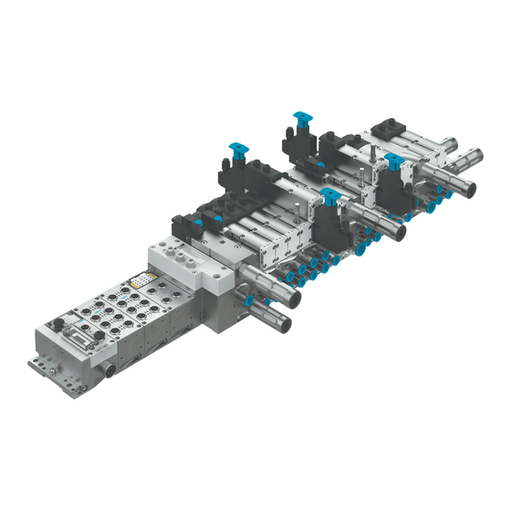
Product overview Additional information – Contact the regional Festo contact if you have technical problems è www.festo.com. – Accessories and spare parts è www.festo.com/catalogue. Product overview Structure 4.1.1 Pneumatic components 4.1.1.1 Overview Fig. 1: Pneumatic components of the valve terminal... - Page 8 The identifiers of the ports and control elements are also given in brackets. Electrical actuation of the valves Type code Electrical actuation VSVA-...-1T1L-... Electrical actuation via coil address (parallel-linked) VSVA-...-1T5L-... Electrical actuation directly via CBUS Tab. 4: Electrical actuation of the valves Festo — VTSA-F-CB — 2021-06a...
- Page 9 – Mechanical spring return – inductive sensor Tab. 5: Variants of the 5/2-way valves Variants of the 5/3-way valves ID code Circuit symbol Description B, QB 5/3-way valve – Mid-position pressurised E, QE 5/3-way valve – Mid-position exhausted Festo — VTSA-F-CB — 2021-06a...
- Page 10 Tab. 6: Variants of the 5/3-way valves Variants of the 2x 3/2-way valves ID code Circuit symbol Description H, QH 2 monostable 3/2-way valves – Normal position: – Closed at control side 14 – Open at control side 12 Festo — VTSA-F-CB — 2021-06a...
- Page 11 ID code Circuit symbol Description 2 monostable 2/2-way valves – Normally closed 2 monostable 2/2-way valves – Normally closed – Vacuum operation on 3 and 5 pos- sible Tab. 8: Variants of the 2x 2/2-way valves Festo — VTSA-F-CB — 2021-06a...
- Page 12 VABV-S6-1Q-G38-CB1-T5 VABV-S6-1Q-G38-CB-T5 For pilot air switching valves VABV-S4-2HS-G18-CB-2T5 VABV-S4-12HS-G-CB-2T5 Tab. 9: Variants of the manifold sub-bases All manifold sub-bases have a black electrical manifold module. Address assignment of the manifold sub-bases è 4.4 Address assignment. Festo — VTSA-F-CB — 2021-06a...
- Page 13 Exhaust air 3/5 common; connecting thread G1/2" – Pneumatic additional supply VABF-S6-1-P8A7-G12-CB – Additional electrical power supply – Internal electrical power supply U – Additional pneumatic supply VABF-S6-1-P8A7-G12-CB1 – Additional electrical power supply – Electrical supply via safe voltage zone Festo — VTSA-F-CB — 2021-06a...
- Page 14 – separate exhausting of exhaust air ducts (3) and (5) for working air – exhausting pilot exhaust air via duct (12) Variants of the right-hand end plate Type code Pilot air supply Connecting thread VABE-S6-1RZ-G12 External G1/2 VABE-S6-1R-G12 Internal Tab. 12: End plate, right-hand, variants Festo — VTSA-F-CB — 2021-06a...
- Page 15 – adjustable, two-stage soft start of the working pressure – single-stage soft start for the pilot air supply from port (1), depending on the variant of the soft start valve – exhausting the working pressure Festo — VTSA-F-CB — 2021-06a...
- Page 16 Switching point from exhausted state to pressurised state in duct (1) Pilot pressure in duct (14) reaches operating pressure p Working pressure in duct (1) reaches half operating pressure p Working pressure in duct (1) reaches full operating pressure p Festo — VTSA-F-CB — 2021-06a...
- Page 17 Duct (1) is exhausted via the soft start valve. If the soft start valve is used for the pilot air supply, an additional duct (14) is exhausted via the soft start valve. Festo — VTSA-F-CB — 2021-06a...
- Page 18 Pilot air from port (1) of the Self-resetting PMZQZ manifold sub-base Pilot air from port (1) of the covered PMZQX manifold sub-base – self-resetting PNZQZ – covered PNZQX Tab. 14: Variants of the soft start valves Festo — VTSA-F-CB — 2021-06a...
- Page 19 Pilot air switching valves without M12 connection are treated as separate bus stations. Variants of pilot air switching valves ID code Circuit symbol Pilot air supply Manual override (MO) CT, CTY Pilot air supply from self-resetting port (2) of the manifold sub-base Festo — VTSA-F-CB — 2021-06a...
- Page 20 Some components of the vertical stacking are only available in single widths. Identification of the pressure regulator plates ID codes are printed on the sides of the pressure regulator plates. The ID codes enable equipment items on the valve terminal to be identified. Festo — VTSA-F-CB — 2021-06a...
- Page 21 ZD, ZDY ducts (2) and (4) downstream from the £ 6 ZI, ZIY directional solenoid valve. – The pressure regulator can only be adjusted in the switched state. Tab. 16: Variants of the pressure regulator plates Festo — VTSA-F-CB — 2021-06a...
- Page 22 Tab. 17: Variants of the reversible pressure regulator plates Reversible pressure regulators cannot be combined with the following valves: • 2x 3/2-way valves (ID code H, QH, K, QK, N, QN) These valves require operating pressure in duct (1) for pneumatic spring return. Festo — VTSA-F-CB — 2021-06a...
- Page 23 Fig. 11: Pressure regulation with a reversible AB pressure regulator – example 1 A-regulator 6 Duct (3) (exhaust) 2 Manifold sub-base 7 Valve 3 Intermediate plate 8 Port (4) 4 Duct (5) (exhaust) 9 Port (2) 5 Duct (1) (working air) 10 B-regulator Festo — VTSA-F-CB — 2021-06a...
- Page 24 (3) and (5) independently of each other. A throttle plate, for example, makes it possible to limit the cylinder speed in response to known flow rate conditions. Some components of the vertical stacking are only available in single widths. Festo — VTSA-F-CB — 2021-06a...
- Page 25 Observe the required pilot pressure for the valves è 12.3 Technical data, pneumatic. Some components of the vertical stacking are only available in single widths. Festo — VTSA-F-CB — 2021-06a...
- Page 26 Flow control screw for adjusting the inten- sity of the ejector pulse LED status and error 7-segment display LED switching status indication for solenoid valve Fig. 15: Operating elements and connections Manual override for vacuum generation Manual override ejector pulse Festo — VTSA-F-CB — 2021-06a...
- Page 27 The separate ducts are marked on the separating seals. If the separating seals are pre-assembled at the factory, the separate ducts are also marked on the manifold sub-bases: Separating seal Identification Separate ducts Separating seal Manifold sub-base – – Supply duct (1) Supply duct (1) Exhaust ducts (3) and Festo — VTSA-F-CB — 2021-06a...
- Page 28 Pilot air duct (14) Supply duct (1) red mark Pilot air duct (14) Supply duct (1) Exhaust ducts (3) and green mark Tab. 21: Identification of the separate ducts Additional information è 4.2.1.4 Forming pressure zones. Festo — VTSA-F-CB — 2021-06a...
-
Page 29: Electrical Components
The pneumatic interface connects the CPX terminal to the pneumatic part of the valve terminal. The pneumatic interfaces with left-hand adapter plate VABA-S6-1-… -AL can be placed centrally in the pneumatic section of a valve terminal VTSA-F-CB and they extend the valve terminal by 3 additional safe voltage zones è 4.2.2.1 Formation of voltage zones. -
Page 30: Display Elements Of The Pneumatic Components
2 Common error LED for soft-start valve 7 Pressure gauge optional 3 LED of solenoid coil 14 of special valves 4 LED pressure switch of the special valves Meaning of the LED displays è 10.1 Diagnostics Festo — VTSA-F-CB — 2021-06a... -
Page 31: Display Elements Of The Electrical Components
The LEDs and the meaning of the LED displays differ depending on the variant of the pneumatic interface: • Pneumatic interfaces VABA-S6-1-X2-CB and VABA-S6-1-X2-3V-CB è 10.1.1.5 LED displays of the pneumatic interfaces. • Pneumatic interfaces with integrated output module CPX-FVDA-P2 è Brief description CPX-FVDA- Festo — VTSA-F-CB — 2021-06a... -
Page 32: Control Elements Of The Pneumatic Components
2 Adjusting knob 7 Manual override of the working valves (for each pilot solenoid) 3 Operating pressure plug screw for one valve 6 Manual override of the special valves position 4 Adjusting screw for controlled flow Festo — VTSA-F-CB — 2021-06a... - Page 33 The basic functions of the manual overrides can be changed by mounting a cover cap for manual overrides è 8.1.2.1 Cover cap for manual override (optional) . Manual overrides of the special valves Manual overrides are mainly used during commissioning è 8.1.1.3 Commissioning the pneumatic components with manual override (MO). Festo — VTSA-F-CB — 2021-06a...
-
Page 34: Connecting Elements Of The Pneumatic Components
3 Working ports (2) and (4), per valve posi- 7 Supply port duct (1) tion 8 Exhaust port duct (1) 4 Port (1), separate operating pressure for 9 Exhaust port duct (3) one valve position Festo — VTSA-F-CB — 2021-06a... -
Page 35: Connection Elements Of The Electrical Components
Service interface, e.g. for operator unit Earth terminal Fieldbus interface, fieldbus-specific Power supply connection 4.1.8 Labelling elements Labelling elements Inscription label for the pneumatic interface Inscription label holders Tab. 22: Labelling elements Function 4.2.1 Pneumatics functions Festo — VTSA-F-CB — 2021-06a... - Page 36 • Supply every pressure zone with working pressure and pilot pressure. Do not form pressure-free zones è 4.2.1.4 Forming pressure zones. • Use only one supply component for the pilot air supply in every pressure zone. • Required pilot pressure at port (12/14) è 12.3 Technical data, pneumatic. Festo — VTSA-F-CB — 2021-06a...
- Page 37 The system can be safely switched off and exhausted in two stages. Use of pilot air switching valves A pilot air switching valve must not be combined with another supply component for duct (14) in one pressure zone. Festo — VTSA-F-CB — 2021-06a...
- Page 38 Fig. 24: Example: 2 pressure zones with pilot air switching valve, soft start valve and working valves 1 Pressure zone 1 4 Separating seal for duct (1) and (14) 2 Pressure zone 2 5 Supply duct (1) 3 Exhaust port for duct (1) 6 Right-hand end plate Festo — VTSA-F-CB — 2021-06a...
- Page 39 Vertical stacking Components of the vertical stacking between the manifold sub-base and valve can be installed to extend the functional range of a valve position. Components Pressure regulator plate Throttle plate è 4.1.1.10 Throttle plate Festo — VTSA-F-CB — 2021-06a...
-
Page 40: Electrical Functions
A total of up to 24 addresses can be controlled via the pneumatic interface. Address extension modules make it possible to generate 24 additional valve addresses in every case. A total of 96 addresses is permitted. Festo — VTSA-F-CB — 2021-06a... - Page 41 – 3 internal safe zones: CH0, CH1, CH2 VABA-S6-1-X2-F1-CB Integrated output module CPX- FVDA-P2 (PROFIsafe) – 2 internal safe zones: CH0, – 1 safe output: CH2 (M12 con- nection) VABA-S6-1-X2-F2-CB Tab. 26: Variants of the pneumatic interfaces Festo — VTSA-F-CB — 2021-06a...
- Page 42 FVDA. – 1 safe output: CH2, with M12 connection VABA-S6-1-X2-F2-CB2-AL Integrated output module CPX- FVDA-P2 (PROFIsafe) powered from external power supply: – 3 internal safe zones: CH0, CH1, CH2 VABA-S6-1-X2-F1-CB2-AL Festo — VTSA-F-CB — 2021-06a...
- Page 43 X0, X1, X2 For configurations with an overall length ³1000 mm adjust load voltage of valves U VABA-S6-1-X2-3V-CB-AL è 12.4 Technical data, elec- trical. Tab. 27: Variants of the zone extension adapter Festo — VTSA-F-CB — 2021-06a...
- Page 44 Duct separation 1/14 Additional supply plate/exhaust plate with address extension for unsafe voltage zone Manifold sub-base with 2 valve positions Vacuum generator Internal pilot air supply of the right-hand end plate Tab. 28: Explanations for example 1 Festo — VTSA-F-CB — 2021-06a...
- Page 45 Without node-specific connection technology Interlinking block with system supply, 7/8", 5-pin CPX pneumatic interface with 3 safe zones (PROFIsafe) Soft-start valve with separate voltage zone Manifold sub-base for switchable pilot air with second valve position Festo — VTSA-F-CB — 2021-06a...
- Page 46 Duct separation 1/3/5/14 Adapter plate with CPX pneumatic interface, for expansion by 3 safe internal zones (PROFI- safe) External pilot air supply right-hand end plate AB / CB Blanking plug Tab. 29: Explanations for example 2 Festo — VTSA-F-CB — 2021-06a...
- Page 47 Without node-specific connection technology Interlinking block with system supply, 7/8", 5-pin CPX pneumatic interface with 3 external power supplies for the zones Soft-start valve with separate voltage zone Manifold sub-base for switchable pilot air with second valve position Festo — VTSA-F-CB — 2021-06a...
-
Page 48: Operating Modes
– 5/3-way mid-position valves (ID codes B, QB, E, QE, G and QG) 4.3.2 Reverse operation The supply duct and the exhaust air ducts are interchanged during reverse operation of the valve terminal: – Compressed air supply via duct (3/5) – Exhausting via duct (1) Festo — VTSA-F-CB — 2021-06a... -
Page 49: Address Assignment
1) The switching signal of the pressure switch can be used in an external controller via the M12 connection. Tab. 31: Address assignment of the working valves 4.4.2 Address assignment of the special valves The special valves are independent bus devices. Festo — VTSA-F-CB — 2021-06a... -
Page 50: Address Assignment Of The Vacuum Generator
– Use suitable lifting equipment for the specified weight è Delivery note. – If present, do not remove the wooden substructure until after transport. Assembly Mounting types Depending on the design of the CPX modules, the following mounting types are possible: Festo — VTSA-F-CB — 2021-06a... -
Page 51: Mounting The Labelling Elements
0.1 mg/m3 ISO 8573-1:2010 [–:–:2] – Mineral oils (e.g. HLP oils to DIN 51524 Parts 1 to 3) or oils based on polyalphaolefins (PAO): maximum residual oil content 5 mg/m3 ISO 8573-1:2010 [–:–:4] Festo — VTSA-F-CB — 2021-06a... -
Page 52: Connecting Pneumatic Lines
– For external pilot air supply, you only need to supply the pilot air at port (14). – If the internal pilot air supply (duct 14) is via a soft start valve or pilot air switching valve, do not connect an additional pilot air supply. Festo — VTSA-F-CB — 2021-06a... - Page 53 – in pneumatic supply plate G1/2 – in pneumatic vertical supply plate Width 18 mm: G1/8 Width 26 mm: G1/4 Width 42 mm: G3/8 Width 52 mm: G1/2 Compressed air – in the soft start valve G1/2 Festo — VTSA-F-CB — 2021-06a...
- Page 54 Width 52 mm: G1/2 1) The valve terminal is already fitted with ports based on the order. 2) The external pilot air is supplied by default via port (14). Tab. 36: Size of the pneumatic ports Festo — VTSA-F-CB — 2021-06a...
- Page 55 Fig. 31: Common pneumatic lines with check valves Valve terminal 1 Valve terminal 2 Central pilot air exhaust line Exhaust lines (3/5) of the valve terminals Central exhaust line (3/5) Pilot exhaust line of the valve terminals Festo — VTSA-F-CB — 2021-06a...
- Page 56 Fig. 33: Right-hand end plate, VABE-…RZ-… for external pilot air supply 1. Check type of pilot air supply for valve terminal. 2. Mount right-hand end plate VABE-… RZ-…. Ä External pilot air can be supplied through port (14). Festo — VTSA-F-CB — 2021-06a...
-
Page 57: Setting Pressure Regulator
7.1.2.5 Removing the tubing 1. Label all pneumatic tubing to avoid confusion when reconnecting them. 2. Press down the lock ring of the fitting, e.g. with the releasing tool QSO from Festo. 3. Remove the tubing from the fitting. 7.1.3... - Page 58 Fig. 36: Locked rotary knob • Push the interlock element 1 laterally out of the rotary knob. Ä The rotary knob is locked in the safety level. To fix the rotary knob, secure the interlock element with a padlock. Festo — VTSA-F-CB — 2021-06a...
-
Page 59: Electrical Installation
• Connect power supply è Description of the CPX system (CPX-SYS-...). • Connect CPX modules è Descriptions of the CPX modules. • Long signal lines reduce the immunity to interference. • Observe the maximum permissible signal cable length of 30 m. Festo — VTSA-F-CB — 2021-06a... -
Page 60: Switching On The Power Supply
• Separate supply of the individual voltage zones è PROFIsafe safe output module CPX-FVDA-P2 Prerequisite: the power supply of the CPX terminal is established. 7.2.3 Pin allocation Pneumatic interface VABA-S6-1-X2-3V-CB and zone extension adapter VABA-S6-1-X2-3V-CB-AL Fig. 38: Ports VABA-S6-1-X2-3V-CB and VABA-S6-1-X2-3V-CB-AL Festo — VTSA-F-CB — 2021-06a... - Page 61 Tab. 38: Pin allocation VABA-S6-1-X2-F2-CB, VABA-S6-1-X2-F2-CB2-AL and VABA-S6-1-X2-F2-CB-AL Electrical connections for valves Zone extension adapter VABA-S6-1-X2-F1-CB2-AL and VABA-S6-1-X2-F2-CB2-AL Pin allocation 7/8" connection 0 V valves not assigned not assigned 24 V valves Tab. 39: Pin allocation VABA-S6-1-X2-F1-CB2-AL and VABA-S6-1-X2-F2-CB2-AL Festo — VTSA-F-CB — 2021-06a...
-
Page 62: Earthing The Valve Terminal
The exhaust times depend on the following factors: – Application, including drives and consumers – Configuration of the valve terminal If the application or the configuration of the valve terminal is changed, recalculate the exhaust times. Festo — VTSA-F-CB — 2021-06a... - Page 63 1. Use a screwdriver to push in the plunger of the MO until the valve switches. Ä The valve moves to switching position. 2. Keep the plunger of the MO pressed. Ä The valve remains in switching position. 3. Release the plunger. Festo — VTSA-F-CB — 2021-06a...
- Page 64 Ä The valve moves to switching position. 2. Turn the plunger 90° clockwise to the stop and leave it in position. Ä The valve remains in switching position. 3. Turn the plunger 90° anti-clockwise to the stop. Festo — VTSA-F-CB — 2021-06a...
- Page 65 2. Turn the manual override attachment in switching position 90° clockwise to the stop. Ä Manual override insert is locked in this position and cannot be removed. The valve remains in switching position. 3. Turn the manual override attachment 90° anticlockwise to the stop. Festo — VTSA-F-CB — 2021-06a...
- Page 66 Ä Valve reverts to normal position. Detenting actuation, automatic reset (VSVA-...YE-...) 1. Press MO down to the stop. Ä The valve moves to switching position. 2. Switch on pilot control. Ä MO is reset by electrical signal. Valve remains switched. Festo — VTSA-F-CB — 2021-06a...
-
Page 67: Completing Commissioning Of The Pneumatic Components
Safe output module CPX-FVDA-P2 Commissioning è Description CPX-FVDA-P2. Parameterisation Process data Process data of the soft start valves The process data belong to the following type codes: – VABF-S6-1-P5A4S2YE-G12-1T5-PA – VABF-S6-1-P5A4S1YE-G12-1T5-PA – VABF-S6-1-P5A4S2S-G12-1T5-PA – VABF-S6-1-P5A4S1S-G12-1T5-PA Festo — VTSA-F-CB — 2021-06a... - Page 68 Tab. 43: Process data of the pilot air switching valves without M12 connection Process data of the pilot air switching valves with M12 connection The process data belong to the following type codes: – VSVA-BT-M32CS2-MYE-A2-1T1L-PZ – VSVA-BT-M32CS1-MYE-A2-1T1L-PZ – VSVA-BT-M32CS2-MS-A2-1T1L-PZ – VSVA-BT-M32CS1-MS-A2-1T1L-PZ No process input data available Festo — VTSA-F-CB — 2021-06a...
- Page 69 Solenoid coils SP15 … SP8 SP0=0: duct error (short circuit or wire break) SP0=1: error-free operation Process output data 23 … 16 Solenoid coils SP23 … SP16 15 … 8 Solenoid coils SP15 … SP8 Festo — VTSA-F-CB — 2021-06a...
-
Page 70: Special Features Of Module Numbering
Number of bus stations Number of assigned module numbers Pneumatic interfaces VABA-S6-1-X1-CB VABA-S6-1-X2-CB VABA-S6-1-X1-3V-CB VABA-S6-1-X2-3V-CB VABA-S6-1-X2-F1-CB 2 (integrated output VABA-S6-1-X2-F2-CB module CPX-FVDA-P2) Pilot air switching valves VSVA-BT-M32CS2-MYE-A2-1T5L-PA VSVA-BT-M32CS2-MYE-A2-1T1L-PZ VSVA-BT-M32CS1-MYE-A2-1T5L-PA VSVA-BT-M32CS1-MYE-A2-1T1L-PZ VSVA-BT-M32CS2-MS-A2- 1T5L-PA VSVA-BT-M32CS2-MS-A2- 1T1L-PZ VSVA-BT-M32CS1-MS-A2- 1T5L-PA VSVA-BT-M32CS1-MS-A2- 1T1L-PZ Festo — VTSA-F-CB — 2021-06a... -
Page 71: Module Parameters
– Error is sent to the bus node. – Error is displayed by the module common error LED. Monitoring can also be set for the entire CPX terminal è Description of CPX system (CPX-SYS -...). Festo — VTSA-F-CB — 2021-06a... -
Page 72: Duct Parameters
The errors are displayed on the valve terminal via error LEDs. Errors can be evaluated via the CPX terminal using the FMT (Festo Maintenance Tool) diagnostic software. Possible errors and messages: – Error: undervoltage of valves (U –... -
Page 73: Diagnostic Interfaces
2 Solenoid coil LED 14 5 Valve width 26 mm 3 Valve width 52 mm 6 Valve width 18 mm Every solenoid coil is assigned an LED. The LEDs show the switching status of the solenoid coils. Festo — VTSA-F-CB — 2021-06a... - Page 74 – Bit on the CPX terminal is set (bit: 1). light Group error LED of the soft start valve P (on the manifold sub-base) red light Error in the valve (group error) – Tab. 50: LED displays of the soft start valves Festo — VTSA-F-CB — 2021-06a...
- Page 75 – Valve undervoltage (U – Wire break (Open Load) – Short circuit at valve VABA-S6-1-X2-F1-CB and VABA-S6-1-X2-F2-CB with integrated output module CPX-FVDA-P2 è Brief description of CPX-FVDA-P2. Tab. 52: LED displays of the pneumatic interfaces Festo — VTSA-F-CB — 2021-06a...
-
Page 76: Fault Clearance
If the original configuration of the valve terminal is changed by replacing components: • Check new configuration in the online configurator for validity • In the event of unclarity contact the regional Festo representative è www.festo.com. 11.1.1 Replacing valves or cover plates Disassembly Unscrew component retaining screws. - Page 77 3.0 Nm ± 20% Pilot air switching valve 1.0 Nm ± 10% Tab. 55: Tightening torques 1 or 2 solenoid coils can be actuated per valve position depending on the manifold sub-base è 4.4 Address assignment. Festo — VTSA-F-CB — 2021-06a...
-
Page 78: Replacing Exhaust Plate Or Exhaust Air Cover
• To keep connections and control elements accessible, follow the assembly sequence. Pressure regulator plate Throttle plate Vertical pressure shut-off plate Vertical supply plate Fig. 42: Assembly sequence for vertical stacking Disassembly 1. Loosen the screws of the components above the new component. Festo — VTSA-F-CB — 2021-06a... -
Page 79: Replacing The Manifold Sub-Bases Or Right-Hand End Plate
1. Disconnect electrical and pneumatic connections. 2. Remove the valve terminal from the mounting surface è Assembly instructions VABV-S6-1Q-..3. Place valve terminal on a flat working surface. 4. Remove the screws of the component and the adjacent component. Festo — VTSA-F-CB — 2021-06a... - Page 80 Ä The components are only held together by the electrical manifold module. 5. Remove the component from the adjacent components. Assembly Manifold sub-base Guide pins Seal (optionally with duct separation) Fig. 43: Assembly of manifold sub-bases Festo — VTSA-F-CB — 2021-06a...
-
Page 81: Converting The Valve Terminal
1. Disconnect electrical and pneumatic connections. 2. Remove valve terminal from the mounting surface. 3. Place valve terminal on a flat working surface. 4. Loosen the manifold sub-base to which a separating seal is to be fitted è Disassembly. Festo — VTSA-F-CB — 2021-06a... - Page 82 If the valve terminal is also equipped with other valves, operate reversible 2x 2/2-way valves (ID code VV) in a separate pressure zone with separate exhaust ducts (3) and (5). 1. Place separating seal on the guide pins of the manifold sub-base. 2. Mount the manifold sub-base è Assembly. Festo — VTSA-F-CB — 2021-06a...
-
Page 83: Converting To Internal Or External Pilot Air Supply
– Information on combining a soft start valve, pneumatic supply plate and right end plate è Assembly instructions VABV-S6-1Q -... 11.2.6 Mounting the vacuum generator Mount the vacuum generator directly adjacent to the right-hand end plate. Festo — VTSA-F-CB — 2021-06a... -
Page 84: Disconnecting The Valve Terminal And Cpx Terminal
Seal Guide pins Manifold sub-base 1. Replace damaged seals. 2. Place the seal on the guide pins. 3. Push the pneumatic interface together with the pneumatic part of the valve terminal. 4. Turn in screws. Festo — VTSA-F-CB — 2021-06a... -
Page 85: Adding Valve Positions
è Disassembly. Assembly 1. Mount additional manifold sub-base and, if necessary, an additional pneumatic supply plate è Assembly. Mount components – Vertical stacking components è Assembly – Valves or cover plates è Assembly Technical data Festo — VTSA-F-CB — 2021-06a... -
Page 86: Ambient Conditions
– Medium [°C] –5 … +50 Relative humidity 0 … 90 Degree of protection IP65 (with cable from the accessories of Festo) Corrosion protection Corrosion resistance class CRC 0 Mounting position Any for wall mounting and support system mounting Resistance to vibration/shock resistance See assembly instructions for terminal CPX/ valve terminal VTSA è... - Page 87 1.0 ± 10% 2.0 ± 10% 3.0 ± 15% 5.0 ± 20% Soft-start valve [Nm] 3 ± 10% Pilot air switching valve [Nm] 1 ± 10% Vacuum generator [Nm] 4 ± 10% Tab. 60: Tightening torques Festo — VTSA-F-CB — 2021-06a...
-
Page 88: Technical Data, Pneumatic
– 5/3-way valves pressure è Graphs below. – 2x 3/2-way valves (ID codes H, K, N, QH, QK, QN) – 2x 2/2-way valves (ID code VC) Tab. 63: Operating pressure/pilot pressure of valves Festo — VTSA-F-CB — 2021-06a... - Page 89 5/2-way valves (ID codes D, J, M, O, QD, QJ, QM, QO) and 5/3-way valves (ID codes B, E, G, QB, QE, Fig. 49: Required pilot pressure p12/14 as a function of the operating pressure p1 of the external pilot air supply Festo — VTSA-F-CB — 2021-06a...
-
Page 90: Valve Switching Times
Valve assembly Valve switching times [ms] Reverse VC, VV 2x 2/2-way valve – H, K, N 2x 3/2-way valve – QH, Qk, QN 5/2-way valve, – – impulse QD, QJ 5/2-way valve, – monostable, air spring Festo — VTSA-F-CB — 2021-06a... - Page 91 H, K, N 2x 3/2-way valve – QH, QH, QN 5/2-way valve, – – impulse 5/2-way valve, – monostable, air spring 5/2-way valve, – monostable, spring B, E, G 5/3-way mid-posi- tion valve QB, QE, QG – Festo — VTSA-F-CB — 2021-06a...
- Page 92 Tab. 67: VSVA-B-… at 24 V DC (width 42 mm) VSVA-B-… at 24 V DC (width 52 mm) ID code Valve assembly Valve switching times [ms] Reverse 2x 2/2-way valve – H, K, N 2x 3/2-way valve – QH, QK, QN Festo — VTSA-F-CB — 2021-06a...
-
Page 93: Flow Rate Tables And Graphs
ID code Valve assembly Standard nominal flow rate [l/ min] VC, VV 2x 2/2-way valve H, K, N 2x 3/2-way valve QH, QK, QN D, J, M, O 5/2-way valve SO, SF QD, QJ, QM, QO Festo — VTSA-F-CB — 2021-06a... - Page 94 5/2-way valve 1350 SO, SF QD, QJ, QM, QO 1100 B (pressurised) 5/3-way mid-position valve Switching position: 1350 Mid-position: 700 E (exhausted) G (closed) QB (pressurised) Switching position: 1000 Mid-position: 700 QE (exhausted) QG (closed) Festo — VTSA-F-CB — 2021-06a...
- Page 95 Valve assembly Standard nominal flow rate [l/ min] 2x 2/2-way valve 3400 H, K, N 2x 3/2-way valve 2600 QH, QK, QN 2200 D, J, M, O 5/2-way valve 3400 QD, QJ, QM, QO 2800 Festo — VTSA-F-CB — 2021-06a...
- Page 96 Tab. 75: Standard nominal flow rate of soft-start valves VABF-S6-1-... Pilot air switching valve Standard nominal flow rate [l/h] Pressurisation Exhaust port VSVA-BT-M32CS... Tab. 76: Standard nominal flow rate of pilot air switching valves VSVA-BT-M32CS... Festo — VTSA-F-CB — 2021-06a...
- Page 97 Pressure regulator plates (P regulator) widths 18 mm and 26 mm at 6 bar Fig. 51: Flow rate qn as a function of output pressure p2 for port (1), input pressure 10 bar, set regulated pressure 6 bar Width 18 mm Width 26 mm Festo — VTSA-F-CB — 2021-06a...
- Page 98 Pressure regulator plates (P regulator), width 52 mm at 10 bar Fig. 53: Flow rate qn as a function of output pressure p2 for port (1), input pressure 10 bar, set regulated pressure 6 bar Festo — VTSA-F-CB — 2021-06a...
- Page 99 Pressure regulator plates (AB-regulator) widths 18 mm and 26 mm at 10 bar Fig. 55: Flow rate qn as a function of output pressure p2 for port (2), (4) or ports (4)/(2), input pressure 10 bar, set regulated pressure 6 bar Width 18 mm Width 26 mm Festo — VTSA-F-CB — 2021-06a...
- Page 100 Pressure regulator plates (AB-regulator) width 52 at 10 bar Fig. 57: Flow rate qn as a function of output pressure p2 for port (2), (4) or ports (4/2), input pressure 10 bar, set regulated pressure 6 bar Festo — VTSA-F-CB — 2021-06a...
- Page 101 Fig. 59: Flow rate qn as a function of output pressure p2 for pressure regulator plates (AB-regulator plates, reversible) for ports (4/2), input pressure 10 bar, set regulated pressure 6 bar Width 18 mm Width 26 mm Festo — VTSA-F-CB — 2021-06a...
- Page 102 Pressure regulator plate (AB-regulator), width 52 mm at 10 bar Fig. 61: Flow rate qn as a function of output pressure p2 for pressure regulator plates (AB-regulator plates, reversible) for ports (4/2), input pressure 10 bar, set regulated pressure 6 bar Festo — VTSA-F-CB — 2021-06a...
- Page 103 Width 26 mm Throttle plates width 42 mm Fig. 63: Flow rate qn as a function of the revolutions n of the adjusting screw Flow rate from (4) to (5) Flow rate from (2) to (3) Festo — VTSA-F-CB — 2021-06a...
-
Page 104: Technical Data, Electrical
Current consumption per solenoid coil with LED at 24 V DC and 100% duty cycle from U 2x 3/2-way valves [mA] 5/2 and 5/3-way valves [mA] all valves – Pick-up current [mA] – – Holding current (after 30 ms) [mA] – Festo — VTSA-F-CB — 2021-06a... - Page 105 EMC emitted interference è Declaration of conformity EMC interference resistance Tab. 77: Technical data, electrical Voltage supply for the vacuum generator VABF Fig. 65: Minimum voltage supply U as a function of ambient temperature EL / SEN Festo — VTSA-F-CB — 2021-06a...
- Page 106 Copyright: Festo SE & Co. KG 73734 Esslingen Ruiter Straße 82 Deutschland Phone: +49 711 347-0 Internet: © 2021 all rights reserved to Festo SE & Co. KG www.festo.com...
Need help?
Do you have a question about the VTSA-F-CB and is the answer not in the manual?
Questions and answers