Table of Contents
Advertisement
Quick Links
Advertisement
Table of Contents

Related Manuals for Festo VTOP


Summary of Contents for Festo VTOP
- Page 1 VTOP Valve terminal Operating instruc- tions 8158463 2021-07 [8158465]...
- Page 2 Translation of the original instructions...
-
Page 3: Table Of Contents
Assembly of valve terminal VTOP........ - Page 4 12.1 Converting valve terminal VTOP ........
-
Page 5: About This Document
About this document About this document Applicable Documents All available documents for the product è www.festo.com/sp. Product designation The following products are designated as follows in this document. Product Product designation in the document Adapter plate Flange module for safety functions VABP VABP-C13-100HFT...- F90-VDE1E... -
Page 6: Safety
Work on the product may only be carried out by qualified personnel who can evaluate the work and detect dangers. The qualified personnel have knowledge and experience in process automation. Additional information – Contact the regional Festo contact if you have technical problems è www.festo.com. – Accessories and spare parts è www.festo.com/catalogue. Festo — VTOP — 2021-07... -
Page 7: Product Overview
Product overview Product overview Function The valve terminal VTOP has a modular design and, depending on the modules used, the following additional pneumatic functions can be implemented: – Compressed air regulation and filtering – Volume flow boost – Reaching a defined end position in the event of a pressure failure –... -
Page 8: Structure
Side B Filter regulator PCRI 4.3.2 Adapter plate VABA The adapter plate VABA is the interface between valve terminal VTOP, pneumatic drive and positioner. Various adapter plates are available, depending on the pneumatic drive. Pneumatic drive Adapter plate VABA-C13-100-... -1-F90-G12 -2-F90-G12 Semi-rotary drive DFPD-240 ... - Page 9 VDI/VDE 3845-1 Module interface Thread Fig. 3: VABA-C13-100-1-F90-G12, view A Pneumatic port for supply air (1) Pneumatic port for exhaust air (3) Product labelling Positioner interface in accordance with VDI/VDE 3847-2 Fig. 4: VABA-C13-100-1-F90-G12, view B Festo — VTOP — 2021-07...
- Page 10 VDI/VDE 3845-1 Module interface Thread Fig. 5: VABA-C13-100-2-F90-G12, view A Pneumatic port for supply air (1) Pneumatic port for exhaust air (3) Product labelling Positioner interface in accordance with VDI/VDE 3847-2 Fig. 6: VABA-C13-100-2-F90-G12, view B Festo — VTOP — 2021-07...
-
Page 11: Volume Booster Vogm
Interface with modules, page A Flow control screw blanking plug duct 4 (only VOGM-FD100-T33H-M-F90, double-acting) Thread Fig. 7: VOGM-FD100-T33H-M-F90, view A Product labelling Transportation lock Interface with modules, page B Seal Cylindrical pin Screw Fig. 8: VOGM-FD100-T33H-M-F90, view B Festo — VTOP — 2021-07... -
Page 12: Filter Regulator Pcri
The filter can be replaced if contaminated è 10.1 Changing the filter. A pressure gauge can be mounted to display the set outlet pressure è 6.3.1 Mounting pressure gauge. The set outlet pressure can be secured against unauthorised adjustment è www.festo.com/catalogue. Filter cover... -
Page 13: Fail-Safe Module Vogi
Pneumatic port for supply air (1) Interface with modules, page A Thread Fig. 11: VOGI-F100FS-T32H-M-F90, view A Product labelling Transportation lock Interface with modules, page B Seal Cylindrical pin Screw Fig. 12: VOGI-F100FS-T32H-M-F90, view B Festo — VTOP — 2021-07... -
Page 14: Flange Module For Safety Functions Vabp
Exhaust duct 2 of the mounted control valve is always directly connected to duct 2 of the pneumatic drive, independently of other modules and module positions of the valve terminal VTOP. The flange module for safety functions VABP only provides the interface for various safety architec- tures and is not a safety device. - Page 15 VDI/VDE 3845-1, side Interface with modules, page A Screw Fig. 15: VABP-C13-100HFT1-F90 -..., view A Product labelling Transportation lock Interface with modules, page B Seal Cylindrical pin Screw Fig. 16: VABP-C13-100HFT1-F90 -..., view B Festo — VTOP — 2021-07...
-
Page 16: End Plate Vabe
4.3.7 End plate VABE The end plate VABE is the terminating module of the valve terminal VTOP and must generally be used. A reversible reversing plate is located inside the end plate VABE. The orientation of the reversing plate defines the effective direction and, at the same time, the end position if the compressed air supply fails in the double-acting pneumatic drive. -
Page 17: Assembly
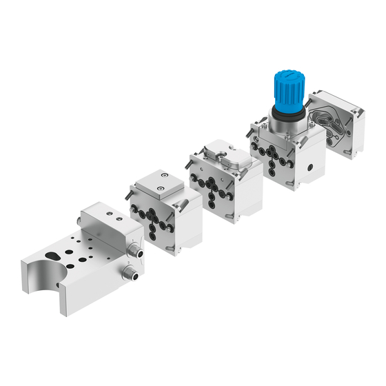
1) If the maximum number of modules is exceeded, additional measures are required to comply with vibration resistance and shock resistance. Tab. 6: Rules for set-up Exemplary structure Adapter plate VABA Volume booster VOGM Fail-safe module VOGI Filter regulator PCRI End plate VABE Fig. 19: Exemplary structure Festo — VTOP — 2021-07... -
Page 18: Assembly Of Valve Terminal Vtop
4. Apply the screws and tighten evenly. Tightening torque: 10 Nm ± 20% Attachment 6.2.1 Attaching valve terminal VTOP The valve terminal VTOP is attached to the pneumatic drive via the adapter plate VABA. • Mount the adapter plate VABA to the pneumatic drive è Assembly instructions for adapter plate VABA. -
Page 19: Attaching Positioner
– – – 1) Not suitable for the valve terminal VTOP. Direct attachment of the positioner is only possible via the control panel DADG-FM -... Tab. 7: Adapter for positioner 1. Select suitable adapters è www.festo.com/catalogue. 2. Attach the positioner to the adapter plate VABA è... - Page 20 1. Check that the seal on the control valves is seated correctly. 2. Mount the control valves at the control valve interface on the flange module for safety functions VABP è Assembly instructions for control valve. Festo — VTOP — 2021-07...
-
Page 21: Installation
Commissioning Installation Pneumatic installation 1. Select suitable fittings and silencers è www.festo.com/catalogue. 2. Screw the fittings and silencers into the corresponding pneumatic connections. Observe the tightening torque. 3. Seal the unused pneumatic ports. Observe the tightening torque. 4. Connect the compressed air lines to the fittings. -
Page 22: Operation
Ä The rotary knob is unlocked. 2. Screw down the rotary knob fully anti-clockwise (–). 3. Pressurise the valve terminal VTOP slowly. 4. Turn the rotary knob clockwise (+) until the desired output pressure is reached (1 bar/revolution). Comply with the pressure regulation range è 13 Technical data. -
Page 23: Fault Clearance
Tab. 8: Fault clearance Modification 12.1 Converting valve terminal VTOP The valve terminal VTOP in converted in reverse order to the mounting è 6 Assembly. The installation rules must be observed è 6.1.1 Rules for set-up. Festo — VTOP — 2021-07... -
Page 24: Reversing Effective Direction
8. Tighten the screw of the reversing plate. Tightening torque: 0.9 Nm ± 10% 9. Assemble the end plate VABA with the module in the correct position. 10. Apply the screws of the end plate VABA and tighten evenly. Tightening torque: 10 Nm ± 20% Festo — VTOP — 2021-07... -
Page 25: Technical Data
1) High corrosion stress. Outdoor exposure under moderate corrosive conditions. External visible parts in direct contact with the ambient atmosphere typical for industrial applications or media such as solvents and cleaning agents, with primarily functional requirements for the surface. Tab. 9: Technical data – Valve terminal VTOP Festo — VTOP — 2021-07... -
Page 26: Adapter Plate Vaba-C13-100
Technical data 13.2 Adapter plate VABA-C13-100 -...- F90-G12 VABA-C13-100-... -1-F90-G12 -2-F90-G12 Design Sub base valve Function Interface between valve terminal VTOP, pneumatic actuator and positioner Ambient temperature [°C] –40 … +80 Transport and storage [°C] –40 … +80 temperature Pneumatic port 1... -
Page 27: Volume Booster Vogm-Fd100
20.3 … 116 Standard nominal flow [l/min] 1240 rate CE marking See declaration of conformity è www.festo.com Product weight 1560 Tab. 11: Technical data – Volume booster VOGM-FD100 -... 33...- M-F90 Ratio of compressed air flow to flow control valve setting Fig. -
Page 28: Filter Regulator Pcri-100-F90-12
Standard nominal flow [l/min] 1400 rate Flow rate [l/min] Dependent on the set outlet pressure CE marking See declaration of conformity è www.festo.com Product weight 1950 Tab. 12: Technical data – Filter regulator PCRI-100-F90-12 -...- T3 Festo — VTOP — 2021-07... -
Page 29: Fail-Safe Module Vogi-F100Fs-T32H-M-F90
0.33 … 0.8 [bar] 3.3 … 8 [psi] 43.5 … 116 Standard nominal flow [l/min] 1093 rate CE marking See declaration of conformity è www.festo.com Product weight Tab. 13: Technical data – Fail-safe module VOGI-F100FS-T32H-M-F90 Festo — VTOP — 2021-07... -
Page 30: Flange Module For Safety Functions Vabp-C13-100Hft
0 … 116 Standard nominal flow [l/min] Dependent on the installed control valve rate CE marking See declaration of conformity è www.festo.com Product weight 1300 1365 Tab. 14: Technical data – Flange module for safety functions VABP-C13-100HFT...- F90 Festo — VTOP — 2021-07... -
Page 31: End Plate Vabe-C13-100-F90-Du
–40 … +80 Operating pressure [MPa] 0 … 0.8 [bar] 0 … 8 [psi] 0 … 116 CE marking See declaration of conformity è www.festo.com Product weight Tab. 15: Technical data – End plate VABE-C13-100-F90-DU Festo — VTOP — 2021-07... - Page 32 Copyright: Festo SE & Co. KG 73734 Esslingen Ruiter Straße 82 Deutschland Phone: +49 711 347-0 Internet: © 2021 all rights reserved to Festo SE & Co. KG www.festo.com...
Need help?
Do you have a question about the VTOP and is the answer not in the manual?
Questions and answers