
Related Manuals for Festo VTSA-F-CB


Summary of Contents for Festo VTSA-F-CB
- Page 1 VTSA-F-CB Valve terminal Instruc- tions | Assembly, Installation 8099814 8099814 2019-08 [8099816]...
- Page 2 Translation of the original instructions ® PROFIsafe is a registered trademark of its respective trademark holder in certain countries. Festo — VTSA-F-CB — 2019-08...
-
Page 3: Table Of Contents
5.2.4.2 Connection elements of the electrical components..........19 5.2.5 Labelling elements....................19 Transport and storage....................20 Mounting........................20 Mounting types......................20 Mounting the labelling elements.................. 20 7.2.1 Mounting/dismounting the identification holder............ 20 Installation........................21 Installation Pneumatics....................21 Festo — VTSA-F-CB — 2019-08... - Page 4 Mounting the cover cap for manual override (optional).......... 36 9.2.2.2 Remove the cover cap for manual override (optional)..........37 Technical data......................38 10.1 Ambient conditions....................... 38 10.2 Technical data, mechanical....................38 10.3 Technical data, pneumatic.....................40 10.4 Technical data, electrical....................42 Festo — VTSA-F-CB — 2019-08...
-
Page 5: About This Document
This document describes the use of the above-mentioned product. Certain aspects of use are described in other documents and must be observed. Other applicable documents / documentations All available documents for the product è www.festo.com/pk. Product labelling Structure of product labelling... -
Page 6: Specified Standards
Do not connect or disconnect plug connector when powered. – Comply with the handling specifications for electrostatically sensitive devices. – Observe further applicable documents. Intended use The VTSA-F-CB valve terminal is designed for switching and controlling compressed air in industrial applications. Festo — VTSA-F-CB — 2019-08... -
Page 7: Range Of Application And Certifications
Work on safety-related systems may only be carried out by safety engineering specialists. Further information – Accessories è www.festo.com/catalogue. – Spare parts è www.festo.com/spareparts. Service Contact your regional Festo contact person if you have technical questions è www.festo.com. Product overview Function 5.1.1 Functions Pneumatics 5.1.1.1 Pressure supply to the valve terminal The valve terminal can be supplied with operating pressure by the following components: –... -
Page 8: Pilot Air Supply
– Ducted pilot exhaust air: the pilot exhaust air is exhausted at the port (12) on the right end plate. Festo — VTSA-F-CB — 2019-08... -
Page 9: Creation Of Pressure Zones
Product overview Convert to ducted pilot exhaust air è Description of VTSA-F-CB. 5.1.1.4 Creation of pressure zones In order to supply valves with different pressures, pressure zones for the working air and the pilot air can be formed within the valve terminal. The pressure zones are limited by separating seals between the manifold sub-bases è... -
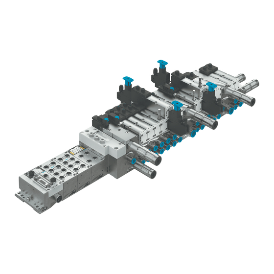
Page 10: Configuration
10 Cover plate 4 Vertical supply plate 11 Pressure regulator plate 5 Pilot air valve 12 Throttle plate 6 Soft start valve 13 Valve 7 Supply plate Fig. 2 Pneumatic components of the valve terminal Festo — VTSA-F-CB — 2019-08... - Page 11 – Exhausting the pilot pressure – Query of the exhausted state with a pressure switch in the pilot control The switching signal of the pressure switch is sent to the CPX terminal. Festo — VTSA-F-CB — 2019-08...
- Page 12 Vacuum generator (optional) 1 Solenoid valve VSVA 2 Vacuum port 3 Silencer 4 Manifold sub-base for valve terminal VTSA-F-CB (pneumatic and electric) 5 Electrical linkage to valve terminal VTSA-F-CB 6 Flow control screw for adjusting the intensity of the ejector pulse...
- Page 13 Fig. 6 Separating seal between manifold sub-bases Pressure zones can be formed in the valve terminal to supply valves with different pressures. The pressure zones are limited by separating seals between the manifold sub-bases. Further information è Description Valve terminal VTSA-F-CB. Festo — VTSA-F-CB — 2019-08...
-
Page 14: Display Components
2 Group error LED of the soft start valve 5 Solenoid coil LED 12 3 LED of solenoid coil 14 of special valves 6 Solenoid coil LED 14 Fig. 7 Display elements of the pneumatic components Meaning of the LED displays è Description VTSA-F-CB. Festo — VTSA-F-CB — 2019-08... -
Page 15: Display Elements Of The Electrical Components
Depending on the variant of the pneumatic interface, the LEDs and the meaning of the LED displays differ: • Pneumatic interfaces VABA-S6-1-X2-CB und VABA-S6-1-X2-3V-CB è Description of VTSA-F-CB. • Pneumatic interfaces with integrated output module CPX-FVDA-P2 è Brief description CPX-FVDA- Festo — VTSA-F-CB — 2019-08... -
Page 16: Control Elements Of The Pneumatic Components
Manual overrides of the working valves Manual overrides are mainly used during commissioning è 9.2.1.2 Commissioning the pneumatic components with manual override (HHB). The valve-actuator combinations can be tested with the manual overrides . Festo — VTSA-F-CB — 2019-08... - Page 17 The basic functions of the manual overrides can be changed by fitting an MO cover capè 9.2.2.1 Mounting the cover cap for manual override (optional). Manual overrides of the special valves Manual overrides are mainly used during commissioning è 9.2.1.2 Commissioning the pneumatic components with manual override (HHB). Festo — VTSA-F-CB — 2019-08...
-
Page 18: Connecting Elements
3 Working ports (2) and (4), per valve position 8 Exhaust port for channel (1) 4 Port (1) (individual operating pressure for 9 Exhaust port channel (3) one valve position) 10 Exhaust port channel (5) Fig. 10 Connecting elements of the pneumatic components Festo — VTSA-F-CB — 2019-08... -
Page 19: Connection Elements Of The Electrical Components
1 Service interface, e.g. operator unit 3 Power supply connection 2 Fieldbus interface (fieldbus-specific) 4 Earth terminal Fig. 11 Connection elements of the electrical components 5.2.5 Labelling elements Fig. 12 Inscription label for the pneumatic interface Festo — VTSA-F-CB — 2019-08... -
Page 20: Transport And Storage
7.2.1 Mounting/dismounting the identification holder Optional identification holders can be mounted on the valves to identify pressure zones and voltage zones. The identification holder provides space for 1 IBS-6X10 inscription label and 2 ASCF-T-Sx labels. Festo — VTSA-F-CB — 2019-08... -
Page 21: Installation
0.1 mg/m3 ISO 8573-1:2010 [–:–:2] – Mineral oils (e.g. HLP oils to DIN 51524 Parts 1 to 3) or oils based on polyalphaolefins (PAO): maximum residual oil content 5 mg/m3 ISO 8573-1:2010 [–:–:4] Festo — VTSA-F-CB — 2019-08... -
Page 22: Pressure Rise In The Overall Supply
– Exhausting via pneumatic supply plates with silencer or exhaust plate – Separate exhaust air ducts by pressure zones è Description VTSA-F-CB. 2. Install check valves in common exhaust lines. 8.1.4 Check prerequisites for vacuum or low pressure operation (valves with Identcode VV) Before connecting valves with Identcode VV, check the requirements for vacuum or low-pressure... -
Page 23: Position And Size Of The Pneumatic Ports
Supply ports for valve terminals with pressure supply via the right-hand end plate 1 Port (14) (optional) 2 Port (5) 3 Port (1) 4 Port (3) 5 Port (12) Fig. 15 Supply ports for valve terminals with pressure supply via the right-hand end plate Festo — VTSA-F-CB — 2019-08... - Page 24 1) Depending on the order, the valve terminal is already equipped with connections. 2) The external pilot air supply is by default fed in via port (14). Tab. 8 Pilot air connections Festo — VTSA-F-CB — 2019-08...
-
Page 25: Common Pneumatic Lines
Mounting the tubing 1. Press the tube into the tubing connection up to the stop. 2. Right end plate in size 2: first mount the tubing at port (1) and then at ports (3) and (5). Festo — VTSA-F-CB — 2019-08... -
Page 26: Removing The Tubing
8.1.5.4 Removing the tubing 1. Label all pneumatic tubing to avoid confusion when reconnecting them. 2. Press down the lock ring of the fitting, e.g. with the releasing tool QSO from Festo. 3. Remove the tubing from the fitting. 8.1.6... - Page 27 Fig. 19 Locked rotary knob • Push the interlock element 1 laterally out of the rotary knob. Ä The rotary knob is locked in the fuse level. To fix the rotary knob, secure the interlock element with a padlock. Festo — VTSA-F-CB — 2019-08...
-
Page 28: Setting Pressure Regulator With Adjusting Screw
Switch on the power supply WARNING! Risk of injury due to electric shock. • For the electrical power supply with extra-low voltages, use only PELV circuits that guarantee a reliable separation from the mains network. • Observe IEC 60204-1/EN 60204-1. Festo — VTSA-F-CB — 2019-08... -
Page 29: Pin Allocation
Fig. 21 Connections of the pneumatic interface VABA-S6-1-X2-3V-CB Pin allocation for plug connector X0 1: not assigned 2: not assigned 3: 0 V CH0 4: +24 V CH0 5: functional earth Tab. 10 Pin allocation pneumatic interface VABA-S6-1-X2-3V-CB Festo — VTSA-F-CB — 2019-08... - Page 30 5: functional earth 1) Unswitched voltage UVAL can be used to supply intelligent load systems (auxiliary supply) 2) All output voltages are likewise derived from the internal contact rail UVAL. Tab. 11 Pin allocation pneumatic interface VABA-S6-1-X2-F2-CB Festo — VTSA-F-CB — 2019-08...
-
Page 31: Earthing The Valve Terminal
Earthing the valve terminal 1 Earth terminal Fig. 22 Earth terminal – Connect the earth terminal to the earth potential with low impedance (short cable with large cross-section). – Further information è Description of the CPX system (CPX-SYS-...). Festo — VTSA-F-CB — 2019-08... -
Page 32: Commissioning
4. With detenting actuation of the HHB: After testing the valves, make sure that all HHBs are unlocked so that the valves are back in nor- mal position. 5. Switch off the compressed air supply after testing the valves. Festo — VTSA-F-CB — 2019-08... - Page 33 Valve returns to normal position (not with bistable 5/2-way valves with ident. code J, D). The detenting/non-detenting function of the manual override can be modified to only non-detenting actuation by mounting the MO cover cap. Festo — VTSA-F-CB — 2019-08...
- Page 34 Non-detenting operation of the HHB via cover cap robust (reset: automatic) 1. Press in the HHB plunger with the manual override (AHB) or screwdriver until the valve switches. Ä The valve reverts to the switching position. Festo — VTSA-F-CB — 2019-08...
- Page 35 3. Turn the manual override attachment counterclockwise by 90° until it stops. Ä Manual override attachment is unlocked. 4. Pull out the manual override attachment. Ä Valve returns to normal position (not with bistable valves, ident. code J, D). Festo — VTSA-F-CB — 2019-08...
-
Page 36: Completing Commissioning Of The Pneumatic Components
Mounting the cover cap for manual override (optional) It takes additional force to remove the cover caps. The snap hooks of the cover caps can be damaged during disassembly. • Mount the cover caps only after commissioning. Festo — VTSA-F-CB — 2019-08... -
Page 37: Remove The Cover Cap For Manual Override (Optional)
It takes additional force to remove the cover caps. The snap hooks of the cover caps can be damaged during disassembly. • Use a suitable screwdriver to lever the cover cap for the MO off the MO. Festo — VTSA-F-CB — 2019-08... -
Page 38: Technical Data
EN 60068-2-27 Tab. 13 Technical data: ambient conditions 10.2 Technical data, mechanical Mechanical Width 18 mm 26 mm 42 mm 52 mm Weights Left end plate (CPX ter- Approx. 80 minal) Complete CPX module Approx. 210 Pneumatic interface 1470 Festo — VTSA-F-CB — 2019-08... - Page 39 Bracket on pneumatic [Nm] 10 % ± supply or manifold sub- base Valve on manifold sub- [Nm] 10 % 10 % 15 % 20 % ± ± ± ± base Cover plate on mani- [Nm] fold sub-base Festo — VTSA-F-CB — 2019-08...
-
Page 40: Technical Data, Pneumatic
Pilot air from con- [bar] 3 10 … nection (1) of the manifold sub-base Pilot air valve [bar] 3 10 … Vacuum generator [bar] 4 8 … – Operating pressure – Pilot pressure [bar] 4 10 … Festo — VTSA-F-CB — 2019-08... - Page 41 10 … valve with internal pilot air supply Directional control [bar] The pilot pressure depends on the operating pressure valves with external Description Valve terminal VTSA-F-CB, Technical data pneu- è pilot air supply matic. – 5/2-way valves – 5/3-way valves –...
-
Page 42: Technical Data, Electrical
Diagnostic message [V DC] 21.6 21.5 … undervoltage UOFF, load voltage outside the functional range DC Electromagnetic compatibility EMC emitted interfer- Declaration of conformity è ence1) EMC immunity to inter- ference Tab. 16 Technical data, electrical Festo — VTSA-F-CB — 2019-08... - Page 44 Copyright: Festo AG & Co. KG Ruiter Straße 82 73734 Esslingen Germany Reproduction, distribution or sale of this document or communic- Phone: ation of its contents to others without express authorization is +49 711 347-0 prohibited. Offenders will be liable for damages. All rights...
Need help?
Do you have a question about the VTSA-F-CB and is the answer not in the manual?
Questions and answers