Festo CPX Assembly Instructions Manual
Hide thumbs
Also See for CPX:
- System manual (235 pages) ,
- Electronic manual (221 pages) ,
- Instructions and assembly (7 pages)
Table of Contents
Advertisement
Quick Links
Assembly instructions (original: de)
8031389
1401NH
[8031391]
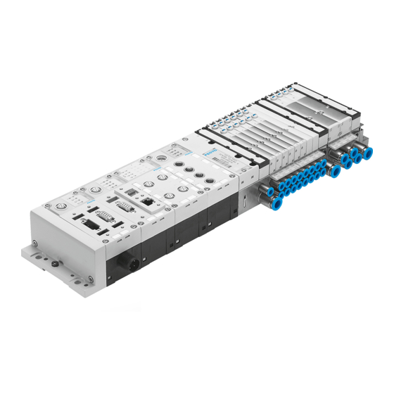
Terminal CPX / Valve terminal VTSA
CPX, CPX-M, VTSA, VTSA-F
1. Safety instructions and notes on mounting .............................................. 1
2. Parts list ................................................................................................... 2
3. Explanations of terms .............................................................................. 2
4. Intended use ............................................................................................ 2
5. Wall mounting .......................................................................................... 3
5a. Check positions of the mountings ....................................................... 3
5b. Assemble mountings ........................................................................... 3
5c. Overview of the mounting points ......................................................... 4
5d. Mount VTSA/VTSA-F-modules (65 mm) ............................................... 5
6. Mounting system assembly ..................................................................... 6
6a. Check positions of the mountings ....................................................... 6
6b. Assemble mountings ........................................................................... 6
6c. Mount CPX-terminal to the mounting system ....................................... 6
7. H-rail mounting ........................................................................................ 7
7a. Mount H-rail ........................................................................................ 7
7b. Mount CPX-terminal to H-rail ............................................................... 7
1)
2)
1)
SL1 = Severity level 1
SL2 = Severity level 2
2)
CPX terminals 1 with 1 ... 3 VTSA/VTSA-F-modules a maximum of one vertical stacking
component per VTSA/VTSA-F-module.
CPX terminals 1 with 4 ... 5 VTSA/VTSA-F-modules a maximum of one vertical stacking
component on the VTSA/VTSA-F-valve terminal.
CPX terminals 1 with more than 5 VTSA/VTSA-F-modules and at least one vertical stacking
on the VTSA/VTSA-F-valve terminal no mounting system assembly permitted.
1. Safety instructions and notes on mounting
Electric voltage.
Injury (death) due to electric shock.
Switch off power supply before assembly work.
†‡
Festo SE & Co. KG
Unexpected movement of components.
Injury due to electric shock, impact, squeezing.
Postfach
Switch off compressed air before assembly work.
73726 Esslingen
Germany
+49 711 347-0
www.festo.com
Electrostatic charge.
Damage to the internal electronics.
Electrostatically discharge assembly personnel prior to assembly work.
Malfunction due to incorrect earthing.
Earth in accordance with regulations
Malfunction and material damage due to incorrect assembly.
Plan sufficient space:
- permit heat dissipation through air circulation
- permit access to the connections.
Requirements of the mounting surface:
- torsion-free operation of the product
- acceptance of the weight and other forces that occur.
Observe assembly conditions ( following tables).
Assembly
CPX-modules (plastic)
CPX-modules (metal) and
VTSA/VTSA-F-modules
(18 ... 52 mm)
VTSA/VTSA-F-modules (65 mm)
Resistance to vibra-
tion/ resistance to
shock
Vibration
Shock
Continuous shock
Vibration load
Frequency range
SL1
2 ... 8
8 ... 27
27 ... 58
58 ... 160
160 ... 200
Shock load
Acceleration
SL1
±150
Continuous shock load
Acceleration
±150
Warning
Caution
Note
Note
CPX-system description: Potential equalisation.
Note
CPX-system description
VTSA/VTSA-F-description of pneumatics.
Wall
√
√
√
in accor-
Wall
dance with
EN 60068
Part 2-6
SL2
Part 2-27 SL2
Part 2-27 SL1
[Hz]
Acceleration
SL2
SL1
2 ... 8
−
8 ... 27
10
27 ... 60
−
60 ... 160
20
160 ... 200
10
2
[m/s
]
Duration
SL2
SL1
±300
11
2
[m/s
]
Duration
6
Mounting
H-rail
system
−
√
√
√
−
−
Mounting
H-rail
system
1)
2)
SL1
SL2
−
2)
SL1
SL2
−
2)
SL1
SL2
−
2
[m/s
]
Displacement
SL2
SL1
SL2
−
±3.5
±7
10
−
−
−
±0.15
±0.7
50
−
−
10
−
−
[ms]
Shocks per direction
SL2
SL1
SL2
11
5
5
[ms]
Shocks per direction
1000
[mm]
1
Advertisement
Table of Contents

Subscribe to Our Youtube Channel
Related Manuals for Festo CPX


Summary of Contents for Festo CPX
-
Page 1: Table Of Contents
Duration Shocks per direction SL1 = Severity level 1 ±150 ±300 SL2 = Severity level 2 CPX terminals 1 with 1 … 3 VTSA/VTSA-F-modules a maximum of one vertical stacking Continuous shock load component per VTSA/VTSA-F-module. [m/s [ms] Acceleration... -
Page 2: Parts List
(3x) 18373d_7 Mounting for CPX-modules (metal): 3. Explanations of terms 3 Mounting bracket 1. The CPX-terminal with VTSA/VTSA-F-valve terminal 1 is designated in CPX-M-BG-RW-... 18373d_3 these assembly instructions as CPX-terminal 1. 4 Screw M3 (thread-cutting) 2. The widths of the VTSA/VTSA-F-modules are designated in these assem- bly instructions as (18 …... -
Page 3: Wall Mounting
Directly fasten VTSA/VTSA-F-modules (65 mm) ( section 5d). Information Check positions of the pre-assembled mountings ( tables) and correct, For CPX-modules (metal) without system supply, the mounting 3 can be as- sembled on both sides of the module. if required ( section 5b). -
Page 4: 5C. Overview Of The Mounting Points
5c. Overview of the mounting points Note Material damage due to incorrect assembly. Select screws suitable for the installation situation. CPX-terminal (plastic) with VTSA/VTSA-F-valve terminal (18 … 52 mm) CPX-terminal (plastic) with VTSA/VTSA-F-valve terminal (65 mm) 18373d_45 18373d_32 Mounting point... -
Page 5: 5D. Mount Vtsa/Vtsa-F-Modules (65 Mm)
10 … 12 , 12 Mounting to every 3rd module Information If the mounting point (M) is covered: Remove module components. Fasten CPX-terminal 1 to the wall. Remount removed components. Assembly Dismantling Mount components. Remove components until Observe tightening torques. -
Page 6: Mounting System Assembly
1.5 Nm ± 10 % 18373d_50 Mountings are pre-assembled, dependent on the configuration. Check positions of the pre-assembled mountings ( tables) and correct, 6c. Mount CPX-terminal to the mounting system if required ( section 5b). Note Mounting 7 for CPX-modules (metal) Material damage due to incorrect assembly. -
Page 7: H-Rail Mounting
7. H-rail mounting 7b. Mount CPX-terminal to H-rail 7a. Mount H-rail Remove pre-assembled Mount H-rail 9 horizon- mountings 2/3/5/7. tally. 18373d_43 On the reverse side of the 18373d_20 modules: Place clamping compo- nents aA on the mounting points (Q).
Need help?
Do you have a question about the CPX and is the answer not in the manual?
Questions and answers