Festo VTSA-F-CB Manual
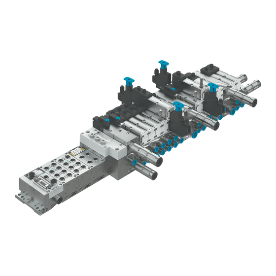
Valve terminal
Hide thumbs
Also See for VTSA-F-CB:
- Instructions, assembly, installation (44 pages) ,
- Manual (106 pages)
Table of Contents
Advertisement
Quick Links
Advertisement
Table of Contents

Related Manuals for Festo VTSA-F-CB


Summary of Contents for Festo VTSA-F-CB
- Page 1 VTSA-F-CB Valve terminal Description | System 8099805 8099805 2020-01 [8099807]...
- Page 2 Translation of the original instructions ® PROFIsafe is a registered trademark of its respective trademark holder in certain countries. Festo — VTSA-F-CB — 2020-01...
-
Page 3: Table Of Contents
5.2.1.9 Throttle plate......................38 5.2.1.10 Vertical Pressure Shut-off Plates................39 5.2.1.11 Vacuum generator (optional).................. 40 5.2.1.12 Separating seals for pressure zone formation............41 5.2.2 Electrical components.....................43 5.2.2.1 Pneumatic interface....................43 5.2.3 Display elements of the pneumatic components.............46 Festo — VTSA-F-CB — 2020-01... - Page 4 Setting pressure regulator with adjusting screw............ 62 8.1.3.3 Set pressure regulator with rotary knob with lock..........62 Electrical Installation..................... 63 8.2.1 Connecting electrical cables................... 63 8.2.1.1 Switch on the power supply................... 63 8.2.1.2 Pin allocation......................64 Festo — VTSA-F-CB — 2020-01...
- Page 5 Converting to Multiple Pressure Zones..............87 11.2.2 Converting to Internal or External Pilot Air Supply..........89 11.2.3 Convert to ducted pilot exhaust air................. 89 11.2.4 Mounting the Pilot Air Valve..................90 11.2.5 Mounting the Soft Start Valve................. 90 Festo — VTSA-F-CB — 2020-01...
- Page 6 Disconnecting the Valve Terminal and CPX Terminal............. 90 11.4 Adding Valve Positions....................92 Disposal........................92 Technical data......................93 13.1 Ambient conditions....................... 93 13.2 Technical data, mechanical....................93 13.3 Technical Data, Pneumatic.................... 95 13.4 Technical data, electrical....................113 Festo — VTSA-F-CB — 2020-01...
-
Page 7: About This Document
About this document This document describes the use of the above-mentioned product. Certain aspects of use are described in other documents and must be observed. Applicable documents All available documents for the product è www.festo.com/pk. Designation Contents Description of the CPX system (CPX-SYS-...) -
Page 8: Specified Standards
Manufacturing month January February March April June July August September October November December Tab. 3 Manufacturing month Specified standards Version ISO 8573-1:2010-04 EN 60204-1:2018-09 IEC 60204-1:2016-10 DIN 51524-1…3:2017-06 Tab. 4 Standards specified in the document Festo — VTSA-F-CB — 2020-01... -
Page 9: Safety
Comply with the handling specifications for electrostatically sensitive devices. – Observe further applicable documents. Intended use The VTSA-F-CB valve terminal is designed for switching and controlling compressed air in industrial applications. Foreseeable misuse – If the load needs to be safely disconnected in safety-critical areas, use connections that have no possibility of short circuit. -
Page 10: Range Of Application And Certifications
The product bears the CE marking. Further information – Accessories è www.festo.com/catalogue. – Spare parts è www.festo.com/spareparts. Service Contact your regional Festo contact person if you have technical questions è www.festo.com. Product overview Function 5.1.1 Functions Pneumatics 5.1.1.1 Pressure supply to the valve terminal The valve terminal can be supplied with operating pressure by the following components: –... -
Page 11: Pilot Exhaust Air
Each pressure zone must be supplied with compressed air via a supplying component è Fig.2. Pres- sure-free zones must not be created. Several pressure zones are required within the valve terminal to operate vacuum or low-pressure-com- patible valves with other valves. Festo — VTSA-F-CB — 2020-01... - Page 12 2 Pressure zone 2 7 Right end plate 3 Pressure zone 3 8 Supply plate 4 Exhaust ducts (3) and (5) 9 Supply duct (1) 5 Separating seal Fig. 2 Example: 3 pressure zones with working valves Festo — VTSA-F-CB — 2020-01...
- Page 13 3 Exhaust port for duct (1) 8 Exhaust ducts (3) and (5) 4 Separating seal 9 Soft start valve 5 Supply duct (1) Fig. 4 Example: 2 pressure zones with soft start valve and working valves Festo — VTSA-F-CB — 2020-01...
-
Page 14: Vertical Stacking
è Tab. 6 Vertical stacking components 5.1.2 Electrical Functions 5.1.2.1 Formation of Voltage Zones With the CPX terminal and the pneumatic interfaces, voltage zones can be formed in the pneumatic part of the valve terminal. Festo — VTSA-F-CB — 2020-01... - Page 15 If a cross-fault proof ballast is voltage zones used: – 1 safe zone VABA-S6-1-X1-CB VABA-S6-1-X2-CB Separate power supply for each If a cross-fault proof ballast is voltage zone possible used: – 3 additional supplies for valves X0, X1, X2 VABA-S6-1-X1-3V-CB Festo — VTSA-F-CB — 2020-01...
- Page 16 VABA-S6-1-X2-F2-CB Tab. 7 Variants of the Pneumatic Interfaces Use of soft start valves The soft start valve completely occupies a safe zone. The system can be safely switched off and exhausted in two stages. Festo — VTSA-F-CB — 2020-01...
- Page 17 2 Soft start valve 1 6 Pilot air valve 3 Monostable valve 7 Vacuum generator 4 Bistable valve 8 System supply of the CPX terminal Fig. 5 Example: pneumatic interface without additional supplies for valves Festo — VTSA-F-CB — 2020-01...
- Page 18 The 3 internal safe zones of the pneumatic interface are assigned as follows in this example: – CH0: Working valves – CH1: soft start valve 1 – CH2: soft start valve 2 The two soft start valves can be safely switched off electrically independently of the working valves. Festo — VTSA-F-CB — 2020-01...
- Page 19 The two internal safe zones of the pneumatic interface are assigned as follows in this example: – CH0: Working valves – CH1: soft start valve 1 The safe output CH2 and the soft start valve can be safely switched off electrically independently of the working valves. Festo — VTSA-F-CB — 2020-01...
- Page 20 Fig. 8 Example: pneumatic interface with 3 additional supplies for valves The 3 internal safe zones of the pneumatic interface are assigned as follows in this example: – CH0: Working valves – CH1: soft start valve 1 Festo — VTSA-F-CB — 2020-01...
-
Page 21: Configuration
10 Cover plate 4 Vertical supply plate 11 Pressure regulator plate 5 Pilot air valve 12 Throttle plate 6 Soft start valve 13 Valve 7 Supply plate Fig. 9 Pneumatic components of the valve terminal Festo — VTSA-F-CB — 2020-01... -
Page 22: Valves
The designations of the connections and control elements are also given in brackets. Variants of the 5/2-way valves Ident. code Circuit symbol Description 5/2-way valve, bistable – Dominant due to port 14 on the control side 5/2-way valve, bistable 5/2-way valve, monostable – Pneumatic spring return Festo — VTSA-F-CB — 2020-01... - Page 23 Variants of the 2x 3/2-way valves Ident. code Circuit symbol Description 2 monostable 3/2-way valves – Normal position: – Closed at control side 14 – Open at control side 12 2 monostable 3/2-way valves – Normally closed Festo — VTSA-F-CB — 2020-01...
- Page 24 Ident. code Circuit symbol Description 2 monostable 2/2-way valves – Normally closed 2 monostable 2/2-way valves – Normally closed – Vacuum operation on 3 and 5 pos- sible Tab. 12 Variants of the 2x 2/2-way valves Festo — VTSA-F-CB — 2020-01...
-
Page 25: Manifold Sub-Bases
Manifold sub-bases for monostable valves (red solenoid coil contact) VABV-S4-1HS-G14-CB-2T2 Manifold sub-bases for soft start valves VABV-S6-1Q-G12-CB-1T5 Manifold sub-bases for pilot air valves VABV-S4-2HS-G18-CB-2T5 VABV-S4-12HS-G-CB-2T5 Tab. 13 Variants of the manifold sub-bases All manifold sub-bases have a black electrical manifold module. Festo — VTSA-F-CB — 2020-01... -
Page 26: Supply Plates
Variants of the supply plates Type code Supply plate with exhaust plate for separate exhaust air VABF-S6-1-P1A6-G12-CB Supply plate with exhaust air cover for common exhaust air VABF-S6-1-P1A7-G12-CB Tab. 14 Variants of the supply plates Festo — VTSA-F-CB — 2020-01... -
Page 27: Right End Plates
è 11.2.2 Converting to Internal or External Pilot Air Supply. • Installing the right end plates è 11.1.4 Replacing the Manifold Sub-bases or Right End Plate. • Combination of soft start valve and right-hand end è 5.1.1.1 Pressure supply to the valve terminalplate . Festo — VTSA-F-CB — 2020-01... -
Page 28: Soft Start Valves With Pressure Monitoring
– Exhausting the pilot pressure – Query of the exhausted state with a pressure switch in the pilot control The switching signal of the pressure switch is sent to the CPX terminal. Festo — VTSA-F-CB — 2020-01... - Page 29 Working pressure in duct (1) reaches half operating pressure p Working pressure in duct (1) reaches full operating pressure p Electrical control signal of the valve inactive Dead time until exhaust of duct (1) Switching point from pressurised state to exhausted state in duct (1) Tab. 16 Festo — VTSA-F-CB — 2020-01...
- Page 30 If the soft start valve is used for the pilot air supply, an additional duct (14) is exhausted via the soft start valve. Variants of the soft start valves Type code Circuit symbol Pilot air supply Manual over- ride (MO) VABF- Pilot air from connection (1) of Self-resetting S6-1-P5A4S1Y- the manifold sub-base E-G12- 1T5-PA Festo — VTSA-F-CB — 2020-01...
-
Page 31: Pilot Air Valves With Pressure Sensing
The pilot air valve can be used for the following purposes: – Switching and exhausting the pilot air The pilot air duct is additionally exhausted unmounted via the exhaust air opening aJon both sides of the pilot air valve. Festo — VTSA-F-CB — 2020-01... - Page 32 VSVA-BT- M32CS1-M- YE-A2-1T1L- – VSVA-BT- Pilot air supply from Covered M32CS2-M- port (2) of the manifold YE-A2-1T5L- sub-base VSVA-BT- M32CS2-M- YE-A2-1T1L- – VSVA-BT- Pilot air supply from M32CS1-M- duct (1) of valve terminal YE-A2-1T5L- or pressure zone Festo — VTSA-F-CB — 2020-01...
-
Page 33: Pressure Regulator Plates
Circuit symbol Description Control range [bar] Pressure regulator plate for port (1) (P-closed-loop controller) VABF-S4-1-R1C2-C-10 – Regulates the oper- £ ating pressure in VABF-S4-2-R1C2-C-10 the duct (1) VABF-S4-1-R1C2-C-10E upstream of the VABF-S4-2-R1C2-C-10E directional solen- oid valve. VABF-S4-1-R1C2-C-6E £ Festo — VTSA-F-CB — 2020-01... - Page 34 Pressure regulator plate for port (2), reversible (B-closed-loop controller) VABF-S4-1-R6C2-C-10E – Reversible valves £ required VABF-S4-2-R6C2-C-10E – The pressure regu- VABF-S4-1-R6C2-C-6E £ lator can be adjus- VABF-S4-2-R6C2-C-6E ted in any state. Festo — VTSA-F-CB — 2020-01...
- Page 35 Reversible pressure regulators cannot be combined with the following valves: • 2x 2/2-way valves (ID codes D and I) • 2x 3/2-way valves (ID code H, K and N) These valves require operating pressure in duct (1) for pneumatic spring return. Festo — VTSA-F-CB — 2020-01...
- Page 36 2 Intermediate plate 7 Duct (3) (exhaust) 3 A-closed-loop controller 8 Port (4) 4 Manifold sub-base 9 Port (2) 5 Duct (5) (exhaust) 10 B-closed-loop controller Fig. 18 Pressure regulation with AB pressure regulator – example Festo — VTSA-F-CB — 2020-01...
-
Page 37: Vertical Supply Plates
In order to supply a single valve position with individual operating pressure or individual pilot pres- sure, a vertical supply plate can be installed between the sub-base and the valve. Some components of the vertical stacking are only available in individual construction widths. Festo — VTSA-F-CB — 2020-01... -
Page 38: Throttle Plate
Some components of the vertical stacking are only available in individual construction widths. Ident. code Circuit symbol Description Restricts the exhaust air after the valve in ducts (3) and (5) Tab. 21 Throttle plate Festo — VTSA-F-CB — 2020-01... -
Page 39: Vertical Pressure Shut-Off Plates
Supplies the valve position with internal pilot air – Pressure reduction via duct (33) VABF-S2…L1D1-C – 3/2-way valve for shutting off the ducts (1) and (14) at the valve pos- ition – Supplies the valve position with internal pilot air Festo — VTSA-F-CB — 2020-01... -
Page 40: Vacuum Generator (Optional)
Vacuum generator (optional) 1 Solenoid valve VSVA 2 Vacuum port 3 Silencer 4 Manifold sub-base for valve terminal VTSA-F-CB (pneumatic and electric) 5 Electrical linkage to valve terminal VTSA-F-CB 6 Flow control screw for adjusting the intensity of the ejector pulse... -
Page 41: Separating Seals For Pressure Zone Formation
Separating seals for pressure zone formation Fig. 24 Separating seal between manifold sub-bases Pressure zones can be formed in the valve terminal to supply valves with different pressures. The pressure zones are limited by separating seals between the manifold sub-bases. Festo — VTSA-F-CB — 2020-01... - Page 42 Separating seal Identification mark Separate ducts Separating seal Manifold sub-base – – Supply duct (1) Supply duct (1) Exhaust ducts (3) and Exhaust ducts (3) and Pilot air duct (14) White mark Festo — VTSA-F-CB — 2020-01...
-
Page 43: Electrical Components
The pneumatic interface connects the CPX terminal to the pneumatic part of the valve terminal. Depending on the pneumatic interface variant, up to 3 safe voltage zones can be formed in the pneu- matic part of the valve terminal è 5.1.2.1 Formation of Voltage Zones. Festo — VTSA-F-CB — 2020-01... - Page 44 – 3 additional supplies for valves X0, X1, X2 VABA-S6-1-X1-3V-CB VABA-S6-1-X2-3V-CB Separate power supply for each Integrated output module CPX- voltage zone possible FVDA-P2 (PROFIsafe) – 3 internal safe zones: CH0, CH1, CH2 Festo — VTSA-F-CB — 2020-01...
- Page 45 Separate power supply for each voltage zone possible Integrated output module CPX- FVDA-P2 (PROFIsafe) – 2 internal safe zones: CH0, – 1 safe output: CH2 (M12 connection) VABA-S6-1-X2-F2-CB Tab. 24 Variants of the Pneumatic Interfaces Festo — VTSA-F-CB — 2020-01...
-
Page 46: Display Elements Of The Pneumatic Components
5 Solenoid coil LED 12 3 LED of solenoid coil 14 of special valves 6 Solenoid coil LED 14 Fig. 26 Display elements of the pneumatic components Meaning of the LED displays è 10.1 Diagnostics. Festo — VTSA-F-CB — 2020-01... -
Page 47: Display Elements Of The Electrical Components
Depending on the variant of the pneumatic interface, the LEDs and the meaning of the LED displays differ: • Pneumatic interfaces VABA-S6-1-X2-CB and VABA-S6-1-X2-3V-CB è 10.1.1.5 LED Displays of the Pneumatic Interfaces. • Pneumatic interfaces with integrated output module CPX-FVDA-P2 è Brief description CPX-FVDA- Festo — VTSA-F-CB — 2020-01... -
Page 48: Control Elements Of The Pneumatic Components
When the pressure supply is switched on, the manual override (MO) can be used to switch a valve to an electrically unactuated, de-energised state. Manual overrides of the working valves Manual overrides are mainly used during commissioning è 9.1.1.3 Commissioning the Pneumatic Components with Manual Override (HHB). Festo — VTSA-F-CB — 2020-01... - Page 49 The basic functions of the manual overrides can be changed by fitting an MO cover capè 9.1.2.1 Mounting the cover cap for manual override (optional). Manual overrides of the special valves Manual overrides are mainly used during commissioning è 9.1.1.3 Commissioning the Pneumatic Components with Manual Override (HHB). Festo — VTSA-F-CB — 2020-01...
-
Page 50: Connecting Elements Of The Pneumatic Components
3 Working ports (2) and (4), per valve position 8 Exhaust port for channel (1) 4 Port (1) (individual operating pressure for 9 Exhaust port channel (3) one valve position) 10 Exhaust port channel (5) Fig. 29 Connecting elements of the pneumatic components Festo — VTSA-F-CB — 2020-01... -
Page 51: Connection Elements Of The Electrical Components
1 Service interface, e.g. operator unit 3 Power supply connection 2 Fieldbus interface (fieldbus-specific) 4 Earth terminal Fig. 30 Connection elements of the electrical components 5.2.8 Labelling elements Fig. 31 Inscription label for the pneumatic interface Festo — VTSA-F-CB — 2020-01... -
Page 52: Operating Modes
The valve terminal is equipped with valve types suitable for reversible operation: – 5/2-way valves (ID codes D, J, M and O) – 5/3-way valves (ID codes B, E, G and VG) – Reversible 2x 2/2-way valves (ID code VV) Festo — VTSA-F-CB — 2020-01... -
Page 53: Address Assignment
1x 26 VABV-S4-1HS- G14-CB-2T2 VABV-S2-1HS-G38-CB- VABV-S2-2S-G12-CB-T2 52 1) The switching signal of the pressure switch can be used in an external controller via the M12 connection. Tab. 25 Address assignment of the working valves Festo — VTSA-F-CB — 2020-01... -
Page 54: Address Assignment Of The Special Valves
Depending on the configuration, the valve terminal can weigh >15 kg and have a large overall length. – Use suitable lifting equipment for the specified weight è Delivery note. – If present, do not remove the wooden substructure until after transport. Festo — VTSA-F-CB — 2020-01... -
Page 55: Mounting
The identification holder provides space for 1 IBS-6X10 inscription label and 2 ASCF-T-Sx labels. 1 Identification holder 2 Mounting on the valve Fig. 33 Mounting the identification holder Assembly • Press the identification holder into the holder on the valve and snap it into place. Festo — VTSA-F-CB — 2020-01... -
Page 56: Installation
When exhausting large-volume actuators or if the exhaust performance is too low, back pressure may build up in the valve terminal's exhaust ducts. This back pressure can lead to pneumatic actuation of other valves, especially with unswitched 3/2-way valves that are normally closed. Festo — VTSA-F-CB — 2020-01... -
Page 57: Check Prerequisites For Vacuum Or Low Pressure Operation
Supply Ports for Valve Terminals with Pressure Supply via the Right-hand End Plate 1 Port (14) (optional) 2 Port (5) 3 Port (1) 4 Port (3) 5 Port (12) Fig. 34 Supply ports for valve terminals with pressure supply via the right-hand end plate Festo — VTSA-F-CB — 2020-01... - Page 58 1) Depending on the order, the valve terminal is already equipped with connections. 2) The external pilot air supply is by default fed in via port (14). Tab. 31 Pilot Air Connections Festo — VTSA-F-CB — 2020-01...
-
Page 59: Common Pneumatic Lines
1 Valve terminal 1 4 Valve terminal 2 2 Central pilot air exhaust line 5 Exhaust line 3/5 3 Central exhaust line (3/5) 6 Pilot air exhaust line Fig. 35 Pneumatic common lines with check valves Festo — VTSA-F-CB — 2020-01... -
Page 60: Connecting The Right End Plate
End Plate VABE-… R-… (Internal Pilot Air Supply) Fig. 36 Right end plate VABE-… R-… (internal pilot air supply) • Check type of pilot air supply for valve terminal. The internally branched pilot air is supplied to the valves only via duct (14). Festo — VTSA-F-CB — 2020-01... -
Page 61: Mounting The Tubing
Removing the tubing 1. Label all pneumatic tubing to avoid confusion when reconnecting them. 2. Press down the lock ring of the fitting, e.g. with the releasing tool QSO from Festo. 3. Remove the tubing from the fitting. Festo — VTSA-F-CB — 2020-01... -
Page 62: Setting Pressure Regulator
Turn the rotary knob lengthwise to the pressure regulator plate. 3. Press the rotary knob into fuse level 1. On pressure regulators in the lockable version, a interlock prevents accidental adjustment of the con- trolled variable. Festo — VTSA-F-CB — 2020-01... -
Page 63: Setting Pressure Regulator With Adjusting Screw
Set pressure regulator with rotary knob with lock 1. Turn the key 90° clockwise. Ä The rotary knob is pressed upwards and is in the control position. 2. Turn the rotary knob completely in the "-" direction. 3. Pressurise valve terminal slowly. Festo — VTSA-F-CB — 2020-01... -
Page 64: Electrical Installation
Electrical installation è Description of the CPX system (CPX-SYS-...). • Address assignment è 5.4 Address Assignment. • Separate supply of the individual voltage zones è PROFIsafeSafe output module CPX-FVDA-P2 Prerequisite: the power supply of the CPX terminal is established. Festo — VTSA-F-CB — 2020-01... -
Page 65: Pin Allocation
Tab. 33 Pin allocation pneumatic interface VABA-S6-1-X2-3V-CB Pin allocation for plug connector X1 1: not assigned 2: not assigned 3: 0 V CH1 4: +24 V CH1 5: functional earth Tab. 33 Pin allocation pneumatic interface VABA-S6-1-X2-3V-CB Festo — VTSA-F-CB — 2020-01... - Page 66 Pin allocation M12 connection of the pilot air valve 1: +24 V SENS 2: not assigned 3: 0 V SENS 4: SENS OUT 5: not assigned Tab. 35 Pin allocation M12 connection of the pilot air valve Festo — VTSA-F-CB — 2020-01...
-
Page 67: Earthing The Valve Terminal
The exhaust times depend on the following factors: – Application, including drives and consumers – Configuration of the valve terminal If the application or the configuration of the valve terminal is changed, recalculate the exhaust times. Festo — VTSA-F-CB — 2020-01... -
Page 68: Testing Valves And Valve/Actuator Combination
5. Switch off the compressed air supply after testing the valves. Non-detenting Operation of the Manual Override (Reset: Automatic) Fig. 44 1. Use a screwdriver to push in the tappet of the MO until the valve switches. Ä The valve reverts to the switching position. Festo — VTSA-F-CB — 2020-01... - Page 69 MO cover cap. Detenting Actuation of the Manual Override (Manual Reset) Fig. 46 1. Use a screwdriver to push in the tappet of the MO until the valve switches. Ä The valve reverts to the switching position. Festo — VTSA-F-CB — 2020-01...
- Page 70 Valve returns to normal position (not with bistable 5/2-way valves with ID codes D and J). Detenting Actuation of HHB via Cover Cap Robust (Reset: Manual) Fig. 48 1. Press in the manual override attachment (AHB) for HHB. Ä The valve reverts to the switching position. Festo — VTSA-F-CB — 2020-01...
- Page 71 Detenting actuation of the manual override (manual reset) Fig. 50 1. Press HHB down to the stop. Ä The valve reverts to the switching position. Fig. 51 2. Pull HHB up to the stop. Ä Valve returns to normal position. Festo — VTSA-F-CB — 2020-01...
-
Page 72: Completing Commissioning Of The Pneumatic Components
It takes additional force to remove the cover caps. The snap hooks of the cover caps can be damaged during disassembly. • Mount the cover caps only after commissioning. 1 Cover cap for MO, non-detenting 2 Cover cap for MO, concealed Fig. 53 Mounting of cover caps for MO, non-detenting and concealed Festo — VTSA-F-CB — 2020-01... -
Page 73: Remove The Cover Cap For Manual Override (Optional)
Safe output module CPX-FVDA-P2 Commissioning è Description CPX-FVDA-P2. Parameterisation 9.3.1 Process Data Process Data of the Soft Start Valves The process data belong to the following type codes: – VABF-S6-1-P5A4S2YE-G12-1T5-PA – VABF-S6-1-P5A4S1YE-G12-1T5-PA – VABF-S6-1-P5A4S2S-G12-1T5-PA – VABF-S6-1-P5A4S1S-G12-1T5-PA Festo — VTSA-F-CB — 2020-01... - Page 74 Tab. 40 Process Output Data of the Pilot Air Valves (Without M12 Connection) Process Data of the Pilot Air Valves (With M12 Connection) The process data belong to the following type codes: – VSVA-BT-M32CS2-MYE-A2-1T1L-PZ – VSVA-BT-M32CS1-MYE-A2-1T1L-PZ – VSVA-BT-M32CS2-MS-A2-1T1L-PZ – VSVA-BT-M32CS1-MS-A2-1T1L-PZ No process input data available Festo — VTSA-F-CB — 2020-01...
- Page 75 0: duct error (short circuit or wire break) – 1: error-free operation Tab. 42 Process Input Data of the Pneumatic Interfaces Byte Description 23 16 Solenoid coils SP23 SP16 … … 15 8 Solenoid coils SP15 SP8 … … Festo — VTSA-F-CB — 2020-01...
-
Page 76: Special Features Of Module Numbering
Active monitoring causes the following: – Error is sent to the bus node. – Error is displayed by the module common error LED. Monitoring can also be set for the entire CPX terminal è Description of CPX system (CPX-SYS -...). Festo — VTSA-F-CB — 2020-01... -
Page 77: Duct Parameters
Depending on the module parameterisation, the errors are reported to the bus node and forwarded to the higher-order controller. The errors are displayed on the valve terminal via error LEDs. Errors can be evaluated via the CPX ter- minal using the FMT (Festo Maintenance Tool) diagnostic software. Possible errors and messages: –... -
Page 78: Diagnostic Interfaces
3 Valve width 52 mm 6 Valve width 18 mm Fig. 55 Arrangement of LEDs for the solenoid coils Each solenoid coil is assigned an LED. The LEDs show the switching status of the solenoid coils. Festo — VTSA-F-CB — 2020-01... -
Page 79: Led Displays Of The Soft Start Valves
Compressed air supply not OK – Pilot exhaust air blocked – Service required LED of the pressure switch Lights – Pressure in duct (1) is exhausted. – Bit on the CPX terminal is set (bit: 1). green Festo — VTSA-F-CB — 2020-01... -
Page 80: Led Displays Of The Pilot Air Valves
LED Displays of the Pneumatic Interfaces Meaning Pneumatic interfaces VABA-S6-1-X2-CB and VABA-S6-1-X2-3V-CB Lights – Initialisation error up red – Diagnostics – Undervoltage of valves (U – Wire break (Open Load) – Short circuit at valve Festo — VTSA-F-CB — 2020-01... -
Page 81: Fault Clearance
Bring the detenting manual the working valves in switching override of the working valves position into the initial position. – Service required Tab. 51 10.3 Repair Send the product to the Festo repair service for repair. Festo — VTSA-F-CB — 2020-01... -
Page 82: Modification
4. Screw in the retaining screws. 5. Tighten retaining screws. – Tightening torques è Tab. 52 Tightening Torques. Width Valve Tightening torque of Spanner size for screw internal hexagon sock- 18 mm VSVA-…-A2 1.0 Nm 10 % ± Festo — VTSA-F-CB — 2020-01... -
Page 83: Replacing Exhaust Plate Or Exhaust Air Cover
Reverse operation of the valve terminal è 5.3.2 Reverse Operation. • When equipped with a vertical pressure shut-off plate è 5.2.1.10 Vertical Pressure Shut-off Plates. • To keep connections and control elements accessible, adhere to the assembly sequence. Festo — VTSA-F-CB — 2020-01... - Page 84 1. Loosen the screws of the components above the new component. 2. Remove components. Assembly 1. Replace damaged seals. 2. Place a new component on the valve position or on a mounted component. 3. Screw in the retaining screws of the new component. Festo — VTSA-F-CB — 2020-01...
-
Page 85: Replacing The Manifold Sub-Bases Or Right End Plate
Address assignment è 5.4 Address Assignment. Disassembly 1. Loosen electrical and pneumatic connections. 2. Remove the valve terminal from the mounting surface è Assembly instructions VABV-S6-1Q -..3. Place valve terminal on a flat working surface. Festo — VTSA-F-CB — 2020-01... - Page 86 Fig. 58 Position of the screws using the example of the right-hand end plate 4. Remove the screws of the component and the adjacent component. Ä The components are only held together by the electrical manifold module. 5. Remove the component from the adjacent components. Festo — VTSA-F-CB — 2020-01...
- Page 87 Modification Assembly 1 Manifold sub-base 3 Seal (optionally with duct separation) 2 Guide pins Fig. 59 Assembly of manifold sub-bases Festo — VTSA-F-CB — 2020-01...
-
Page 88: Converting The Valve Terminal
In order to convert the valve terminal to 2 and more pressure zones, the following components are required for each pressure zone: – Separating seal VABD-S6-1 -...- C – Pneumatic supply plate with exhaust plate or exhaust air cover VABF -...- 1P1A... Festo — VTSA-F-CB — 2020-01... - Page 89 3 Valves in pressure zone 3 7 Supply plate with port (1) for compressed 4 Pneumatic supply plate with port (1) for air supply to pressure zone 1 compressed air supply to the pressure zone Fig. 61 Conversion to several pressure zones Festo — VTSA-F-CB — 2020-01...
-
Page 90: Converting To Internal Or External Pilot Air Supply
2 Display window on control side 12 Fig. 62 Convert to ducted pilot exhaust air 2. Insert the seal with the designation label into the display window on control side 12. 3. Mount the valve on the manifold sub-base. Festo — VTSA-F-CB — 2020-01... -
Page 91: Mounting The Pilot Air Valve
1. Loosen electrical and pneumatic connections. 2. Remove valve terminal from the mounting surface. 3. Remove the screws between the pneumatic interface and the pneumatic part of the valve termin- Replace pneumatic interface è Description of CPX system (CPX-SYS -...). Festo — VTSA-F-CB — 2020-01... - Page 92 3. Push the pneumatic interface together with the pneumatic part of the valve terminal. 4. Turn in screws. 5. Tighten screws. – Tightening torque 3.0 Nm (± 10 %) 6. Place the valve terminal on the mounting surface. 7. Connect pneumatic lines è 8.1.2 Connecting Pneumatic Lines. Festo — VTSA-F-CB — 2020-01...
-
Page 93: Adding Valve Positions
è Assembly. 2. Mount components – Vertical stacking components è Assembly – Valves or cover plates è Assembly Disposal ENVIRONMENT! Send the packaging and product for environmentally sound recycling in accordance with the current regulations è www.festo.com/sp. Festo — VTSA-F-CB — 2020-01... -
Page 94: Technical Data
EN 60068-2-27 Tab. 55 Technical data: ambient conditions 13.2 Technical data, mechanical Mechanical Width 18 mm 26 mm 42 mm 52 mm Weights Left end plate (CPX ter- Approx. 80 minal) Complete CPX module Approx. 210 Pneumatic interface 1470 Festo — VTSA-F-CB — 2020-01... - Page 95 Bracket on pneumatic [Nm] 10 % ± supply or manifold sub- base Valve on manifold sub- [Nm] 10 % 10 % 15 % 20 % ± ± ± ± base Cover plate on mani- [Nm] fold sub-base Festo — VTSA-F-CB — 2020-01...
-
Page 96: Technical Data, Pneumatic
Pilot air from con- [bar] 3 10 … nection (1) of the manifold sub-base Pilot Air Valve [bar] 3 10 … Vacuum generator [bar] 4 8 … – Operating pressure – Pilot pressure [bar] 4 10 … Festo — VTSA-F-CB — 2020-01... - Page 97 10 … valve with internal pilot air supply Directional control [bar] The pilot pressure depends on the operating pressure valves with external Description Valve terminal VTSA-F-CB, Technical data pneu- è pilot air supply matic. – 5/2-way valves – 5/3-way valves –...
- Page 98 2 Operating range for valves with external pilot air supply Fig. 64 Required pilot pressure of the external pilot air supply for 2x 2/2-way valves (ID codes VC, VV) and 2x 3/2-way valves (ident. codes H, K, N) Festo — VTSA-F-CB — 2020-01...
- Page 99 The fittings of the pneumatic ports reduce the nominal flow rate of the valves. Standard nominal flow rates valves VSVA-B-... (width 18 mm) ID code Valve assembly Standard nominal flow rates [l/min] 2x 2/2-way valve 2x 3/2-way valve 5/2-way valve Festo — VTSA-F-CB — 2020-01...
- Page 100 Tab. 59 Standard Nominal Flow Rates Valves VSVA-B-..., Width 26 mm Standard nominal flow rates valves VSVA-B-... (width 42 mm) ID code Valve assembly Standard nominal flow rates [l/min] 2x 2/2-way valve 1500 2x 3/2-way valve 1300 Festo — VTSA-F-CB — 2020-01...
- Page 101 B (pressurised) 5/3-way mid-position valve Switching position: 3200 Mid-position: 1700 E (exhausted) G (closed) VG (pressurised 1 to 2, 4 to 5 Switching position: 2600 closed) Mid-position: 900 Tab. 61 Standard Nominal Flow Rates Valves VSVA-B-..., Width 52 mm Festo — VTSA-F-CB — 2020-01...
- Page 102 5/2-way valve, monostable, spring 5/3-way mid-posi- tion valve 1) Measuring method 0 - 10 %, according to FN 942032 Tab. 64 Valve Switching Times VSVA-B-... With Nominal Operating Voltage 24 V DC (18 mm wide) Festo — VTSA-F-CB — 2020-01...
- Page 103 Valve Switching Times VSVA-B-... With Nominal Operating Voltage 24 V DC (42 mm wide) ID code Valve assembly Valve switching times [ms] Reverse – 2x 2/2-way valve 2x 3/2-way valve – – 5/2-way valve, impulse Festo — VTSA-F-CB — 2020-01...
- Page 104 – – 5/2-way valve, impulse – 5/2-way valve, monostable, air spring 5/2-way valve, monostable, spring 5/3-way mid-posi- tion valve Tab. 67 Valve Switching Times VSVA-B-... With Nominal Operating Voltage 24 V DC (52 mm wide) Festo — VTSA-F-CB — 2020-01...
- Page 105 … … … port (4) (A- closed-loop controller) Pressure regu- 2 10 1 10 … … lator plate for 0.5 10 … ports (2) 2 6 1 6 … … and (4) (AB- 0.5 6 closed-loop … controller) Festo — VTSA-F-CB — 2020-01...
- Page 106 0.5 6 … port (4), reversible (A- closed-loop controller) Pressure regu- 0.5 10 … lator plate for port (2), 0.5 6 … reversible (B- closed-loop controller) Tab. 70 Control Ranges of the Pressure Regulators Festo — VTSA-F-CB — 2020-01...
- Page 107 (1), 6 bar 1 Width 18 mm 2 Width 26 mm Fig. 67 Flow rate qn as a function of output pressure p2 with pressure regulator plates (P regulator plate) for port (1), 10 bar Festo — VTSA-F-CB — 2020-01...
- Page 108 [l/min] Fig. 69 Flow rate qn as a function of output pressure p2 with pressure regulator plates (P regulator plate) for port (1), input pressure 10 bar, set regulated pressure 6 bar, width 52 mm Festo — VTSA-F-CB — 2020-01...
- Page 109 1 Width 18 mm 2 Width 26 mm Fig. 71 Flow rate qn as a function of output pressure p2 for pressure regulator plates (AB regulator plates) for port (2), (4) or ports (4)/(2), 10 bar Festo — VTSA-F-CB — 2020-01...
- Page 110 Fig. 73 Flow rate qn as a function of output pressure p2 for pressure regulator plates (AB regulator plates) for port (2), (4) or ports (4/2), input pressure 10 bar, set regulated pressure 6 bar, width 52 Festo — VTSA-F-CB — 2020-01...
- Page 111 (4/2), reversible, 6 bar 1 Width 18 mm 2 Width 26 mm Fig. 75 Flow rate qn as a function of output pressure p2 for pressure regulator plates (AB regulator plates, reversible) for ports (4/2), reversible, 10 bar Festo — VTSA-F-CB — 2020-01...
- Page 112 Fig. 77 Flow rate qn as a function of output pressure p2 for pressure regulator plates (AB regulator plates, reversible) for ports (4/2), reversible, input pressure 10 bar, set regulated pressure 6 bar, width 52 mm Festo — VTSA-F-CB — 2020-01...
- Page 113 Fig. 78 Flow rate qn as a function of the rotations of the adjusting screw n, widths 18 mm and 26 mm 1 Flow rate from (4) to (5) 2 Flow rate from (2) to (3) Fig. 79 Flow rate qn as a function of the rotations of the adjusting screw n, width 42 mm Festo — VTSA-F-CB — 2020-01...
-
Page 114: Technical Data, Electrical
Current consumption per solenoid coil with LED at 24 V DC and 100% duty cycle 2x 3/2-way valves [mA] 5/2 and 5/3-way valves [mA] All valves – – Pick-up current [mA] – – Holding current [mA] (after 30 ms) Festo — VTSA-F-CB — 2020-01... - Page 115 EMC emitted interfer- Declaration of conformity è ence1) EMC immunity to inter- ference Tab. 71 Technical data, electrical 1 Voltage supply U 2 Ambient temperature EL/SEN Fig. 81 Minimum voltage supply for the vacuum generator VABF Festo — VTSA-F-CB — 2020-01...
- Page 116 Copyright: Festo SE & Co. KG Ruiter Straße 82 73734 Esslingen Germany Phone: +49 711 347-0 Internet: © 2020 all rights reserved to Festo SE & Co. KG www.festo.com...
Need help?
Do you have a question about the VTSA-F-CB and is the answer not in the manual?
Questions and answers