Festo VTSA Series Manual
Valve terminal with vtsa pneumatics
Hide thumbs
Also See for VTSA Series:
- Description (267 pages) ,
- Description pneumatics (256 pages) ,
- Manual (166 pages)

Related Manuals for Festo VTSA Series


Summary of Contents for Festo VTSA Series
- Page 1 Valve terminal VTSA / VTSA−F Manual VTSA pneumatics Valve terminal with VTSA pneumatics Type VTSA−44−FB Type VTSA−44−MP... Type VTSA−F−45−FB... Type VTSA−F−45−MP... Manual 538 923 en 0705c [703 978]...
- Page 3 ....... . . 538 923 E(Festo AG & Co. KG, D 73726 Esslingen, Federal Republic of Germany, 2007) Internet: http://www.festo.com E−Mail:...
- Page 4 Contents and general safety instructions ® CAGE CLAMP CAGE CLAMP® is a registered trade mark of WAGO Kontakt technik GmbH, 32385 Minden, Germany Festo P.BE−VTSA−44−EN en 0705c...
-
Page 5: Table Of Contents
Operating the VTSA... valve terminal with reversible 2x3/2−way valves ....... 3−18 Festo P.BE−VTSA−44−EN en 0705c... - Page 6 ........5−23 Festo P.BE−VTSA−44−EN en 0705c...
- Page 7 ............C−1 Festo P.BE−VTSA−44−EN en 0705c...
- Page 8 Contents and general safety instructions Festo P.BE−VTSA−44−EN en 0705c...
-
Page 9: Intended Use
National and local safety regulations must also be observed. Target group This manual is directed exclusively at technicians trained in control and automation technology. Service Please consult your local Festo repair service if you have any technical problems. Festo P.BE−VTSA−44−EN en 0705c... -
Page 10: Notes On The Use Of This Manual
Information on CPX modules can be found in the manual for the relevant module. The following table provides an overview. All valve terminals with multipin node (Sub−D, cage clamp, M23 round plug, M12 individual connections): Information on electric/electronic components: see leaflet with product. VIII Festo P.BE−VTSA−44−EN en 0705c... - Page 11 CPX−... Table 0/1: Manuals on valve terminals with CPX terminal Festo P.BE−VTSA−44−EN en 0705c...
-
Page 12: Important User Instructions
... means that failure to observe this instruction may result in damage to property. The following pictogram marks passages in the text which describe activities with electrostatically sensitive compo nents. Electrostatically sensitive devices: Incorrect handling can result in damage to components. Festo P.BE−VTSA−44−EN en 0705c... - Page 13 Pictograms Information Recommendations, tips and references to other sources of information. Accessories: Information on necessary or useful accessories for the Festo product. Environment: Information on environment−friendly use of Festo products. Text markings The bullet indicates activities which may be carried out in ·...
- Page 14 18 mm and 26 mm with locations for two valves size ISO 1 (size 42 mm) with location for one valve per valve location with work connections 2 and 4. Manual override Manual override actuator Festo P.BE−VTSA−44−EN en 0705c...
- Page 15 Solenoid valve with single−solenoid, double−solenoid or mid−posi tion valve Valve terminal VTSA... Valve terminal VTSA (type 44) or VTSA−F (type 45) with CPX terminal or with multipin node (Sub−D, cage clamp, M23 round plug or IC). XIII Festo P.BE−VTSA−44−EN en 0705c...
- Page 16 Contents and general safety instructions Term/abbreviation Meaning Vertical pressure isolating Plate on a valve location for isolating the valve pressure supply plate Vertical supply plate Plate on a valve location for individual pressure supply Table 0/2: Product−specific terms and abbreviations Festo P.BE−VTSA−44−EN en 0705c...
-
Page 17: Overview Of Components
Overview of components Chapter 1 1−1 Festo P.BE−VTSA−44−EN en 0705c... - Page 18 Description of components ....... . 1−7 1−2 Festo P.BE−VTSA−44−EN en 0705c...
- Page 19 Information on the electronics of the VTSA... valve terminal with multipin connection can be found in the relevant brief description. Information on the modules of the CPX terminal can be found in the CPX System Manual. 1−3 Festo P.BE−VTSA−44−EN en 0705c...
-
Page 20: The Vtsa
1. Overview of components The VTSA... valve terminal Festo assists you in solving your automation tasks at machine level with VTSA... valve terminals. The modular structure of the valve terminal enables you to match it optimally in your machine or system. - Page 21 M23 round plug. strip). Multipin node IC: The valves are connected electrically individually via the IC connections on the multipin node. Table 1/1: Electrical connection variants of the VTSA... valve terminal 1−5 Festo P.BE−VTSA−44−EN en 0705c...
- Page 22 2) Sizes 18 mm and 26 mm 3) Size ISO 1 4) If the VTSA is fitted only with these manifold sub−bases (these sub−bases support control of two valve solenoid coil per valve location) Table 1/2: Number of valve positions 1−6 Festo P.BE−VTSA−44−EN en 0705c...
-
Page 23: Description Of Components
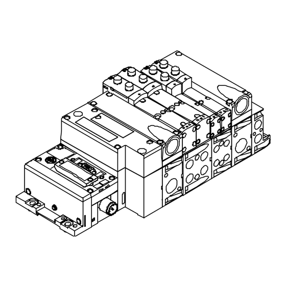
Sub−base with angled connections Valves (optional) Exhaust port cover Vertical supply plate (optional) Right−hand end plate Flow control plate (optional) Pneumatic supply plates (optional) Manifold sub−base Fig. 1/1: Pneumatic components of the VTSA... valve terminal 1−7 Festo P.BE−VTSA−44−EN en 0705c... - Page 24 The VTSA... valve terminal with multipin node Sub−D consists of the following electric components: Multipin socket with cable Multipin node Sub−D connection Fig. 1/3: Electric components of the VTSA... valve terminal with Multipin node Sub−D 1−8 Festo P.BE−VTSA−44−EN en 0705c...
- Page 25 The VTSA... valve terminal with multipin M23 round plug con sists of the following electric components: Multipin node M23 round plug Fig. 1/5: Electric components of the VTSA... valve terminal with multipin node M23 round plug 1−9 Festo P.BE−VTSA−44−EN en 0705c...
- Page 26 The VTSA... valve terminal can be fitted with 2x3/2−way valves (standard and reversible), 5/2−way valves (single−solenoid and double−solenoid) and 5/3−way mid−position valves. All 5/2−way valves and 5/3−way mid−position valves can be used under all operating conditions: Standard mode Reversible mode Low−pressure mode Vacuum mode 1−10 Festo P.BE−VTSA−44−EN en 0705c...
- Page 27 3/2−way valves, closed in basic position. You can identify the valve functiion with the aid of the following table. In the sales documentation and in the Festo Configu rator the valves are marked with an Ident. code. Identifier in Ident.
- Page 28 If on the other hand, only manifold sub−bases which control only one valve coil per valve location are used, the valve ter minal can only be fitted with single−solenoid 5/2−way valves, identifier M52... 1−12 Festo P.BE−VTSA−44−EN en 0705c...
- Page 29 Type code VABV−S4−...T1 VABV−S4−...T2 Identifier code on the type plate Black dot of the manifold sub−base Colour of valve coil contact black Table 1/5: Identifying the manifold sub−bases 1−13 Festo P.BE−VTSA−44−EN en 0705c...
- Page 30 A pressure zone separation of pilot channels 12 and 14 is not therefore possible. You can ascertain the number of pressure zones with which your valve terminal is equipped, by the marking on the sealing plate (see diagram). 1−14 Festo P.BE−VTSA−44−EN en 0705c...
- Page 31 In the case of the selector end plate, the control type and the type of removal of exhaust or breathable air (ducted or non−ducted) can be selected. 1−15 Festo P.BE−VTSA−44−EN en 0705c...
- Page 32 You can fit further pneumatic components in each location between the manifold sub−base and the valve. This vertical stacking will enable you to implement certain additional effects as desired. The following diagram shows the available components: 1−16 Festo P.BE−VTSA−44−EN en 0705c...
- Page 33 Type VABV...T2 supports control of two valve solenoid coils per valve location. 1) Notes on installing the vertical stacking components see chapter 3 Table 1/7: Components of the pneumatic module of the VTSA... valve terminal 1−17 Festo P.BE−VTSA−44−EN en 0705c...
- Page 34 P−pressure regulator with 0 bar input pressure. You can identify the vertical stacking components with the aid of the following table: In the sales documentation and in the Festo Configurator the valves are marked with an Ident. code. Identifica Ident.
- Page 35 Application example: An equal working pressure is required at working ports 2 and 4. A lower working pressure (e.g. 3 bar) is required than the operating pressure present at the valve terminal (e.g. 8 bar). 1−19 Festo P.BE−VTSA−44−EN en 0705c...
- Page 36 4 to the pressure regulator and then via the valve in channel 5. Connection 2 (B) Connection 4 (A) Channel 5 (exhaust) Channel 3 (exhaust) Channel 1 (supply air) Fig. 1/8: AB pressure regulator 1−20 Festo P.BE−VTSA−44−EN en 0705c...
- Page 37 3 and 5 on the valve. In the valve, the supply air is routed to port 2 of the manifold sub−base. The exhaust is passed via channel 4 in the pressure regulator plate and split there to channels 3 and 5 and exhausted. 1−21 Festo P.BE−VTSA−44−EN en 0705c...
- Page 38 The operating pressure is always present on the pressure regulator because regulating takes place in front of the valve, i.e. the regulator can always be set. On the AB pres sure regulator the valve must switch for this. 1−22 Festo P.BE−VTSA−44−EN en 0705c...
- Page 39 When fast exhaust performance is required. If the pressure regulator is always to be set. Notes on installing this pressure regulator see chapter 3.3.6 You will find the following pneumatic connecting and operat ing elements on the VTSA... valve terminal: 1−23 Festo P.BE−VTSA−44−EN en 0705c...
- Page 40 Supply connection (1) Operating non−locking function of manual over pressure" ride Work connections (2) and (4), for Identification fields each valve location Fig. 1/10: Pneumatic connecting, display and operating elements of the VTSA... valve terminal 1−24 Festo P.BE−VTSA−44−EN en 0705c...
- Page 41 Adjusting knob with grid locking (with sizes 18 mm and 26 mm free−wheeling) Connection 1 (individual operating pressure for one valve location) Fig. 1/11: Operating and connecting elements of the components for vertical linking 1−25 Festo P.BE−VTSA−44−EN en 0705c...
- Page 42 Yellow LEDs: sgnal status display of Red LED Common error display of the pilot solenoids valves Voltage supply connection Earth connection Fig. 1/12: Electrical connecting, display and operating elements of the VTSA... valve ter minal with CPX terminal 1−26 Festo P.BE−VTSA−44−EN en 0705c...
- Page 43 Sub−D multipin socket with cable Sub−D connection Yellow LEDs: signal status display of the Inscription field pilot solenoids Earth connection Fig. 1/13: Electrical connecting and display elements of the VTSA... valve terminal with multipin node Sub−D 1−27 Festo P.BE−VTSA−44−EN en 0705c...
- Page 44 Internal earth connection for the con Yellow LEDs: signal status display of the necting cable pilot solenoids Terminal strip Cable routing Inscription field Fig. 1/14: Electrical connecting and display elements of the VTSA... valve terminal with multipin node cage clamp 1−28 Festo P.BE−VTSA−44−EN en 0705c...
- Page 45 Inscription field Yellow LEDs: signal status display of the pilot solenoids M23 round plug as per CNOMO E03.62.530.N Fig. 1/15: Electrical connecting and display elements of the VTSA... valve terminal with multipin node M23 round plug 1−29 Festo P.BE−VTSA−44−EN en 0705c...
- Page 46 VTSA... valve terminal with multipin node IC: M12 individual connections (IC) External earth connection Yellow LEDs: sgnal status display of the pilot solenoids Fig. 1/16: Electric components of the VTSA... valve terminal with multipin node IC 1−30 Festo P.BE−VTSA−44−EN en 0705c...
-
Page 47: Mounting
Mounting Chapter 2 2−1 Festo P.BE−VTSA−44−EN en 0705c... - Page 48 ....2−13 Fitting/removing the manual override caps (optional) ....2−14 2−2 Festo P.BE−VTSA−44−EN en 0705c...
-
Page 49: Mounting
Information on fitting and dismantling the I/O modules can be found in the manual for the CPX I/O modules. Information on fitting modules and components ordered at a later stage can be found in the leaflet supplied with the product. 2−3 Festo P.BE−VTSA−44−EN en 0705c... -
Page 50: General Instructions On Fitting And Dismantling
The specified torques must be observed. Electrostatically sensitive components. Do not therefore touch any contact surfaces. Valve terminals with multipin node Sub−D: Protect the multipin node against humidity, dirt and dust etc. before the connecting cable is fitted. 2−4 Festo P.BE−VTSA−44−EN en 0705c... -
Page 51: Fitting Variants
Table 2/1: Methods of fitting the VTSA... valve terminal Note Fit the VTSA... valve terminal so that there is sufficient space for heat dissipation and ensure that the maximum limits for temperatures are observed (see Technical spec ifications"). 2−5 Festo P.BE−VTSA−44−EN en 0705c... -
Page 52: Fitting Onto/Removing From A Hat Rail
Mounting kit type CPA−BG−NRH. This kit contains 2 M4x10 screws and 2 clamping elements. For VTSA... valve terminals with CPX terminal: Mounting kit type CPX−CPA−BG−NRH This kit contains 3 M4x10 screws and 3 clamping elements. 2−6 Festo P.BE−VTSA−44−EN en 0705c... - Page 53 2. Fit the hat rail (support rail EN 60715 − 35x7.5; width 35 mm, height 7.5 mm). Make sure there is sufficient space for connecting the supply cables and tubing. 3. Fasten the hat rail to the fastening surface at intervals of approx. every 100 mm. 2−7 Festo P.BE−VTSA−44−EN en 0705c...
- Page 54 Fig. 2/1: Fitting the VTSA... valve terminal onto a hat rail 7. Secure the VTSA... valve terminal, as with the CPX ter minal, against tilting or sliding by tightening the locking screw with 1.3 Nm. 2−8 Festo P.BE−VTSA−44−EN en 0705c...
- Page 55 2. Swing the VTSA... valve terminal forwards from the hat rail (see Fig. 2/3, arrow (B)). 3. Lift the valve terminal off the hat rail (see Fig. 2/3, arrow (A)). 2−9 Festo P.BE−VTSA−44−EN en 0705c...
-
Page 56: Fitting Onto/Removing From A Hat Rail
Fig. 2/3: Removing the VTSA... valve terminal from the hat rail 2.2.2 Fitting onto/removing from a hat rail The following components contain holes for fitting the valve terminal onto a wall (see Table 2/3). End plates Pneumatic interface Multipin node 2−10 Festo P.BE−VTSA−44−EN en 0705c... - Page 57 Make sure there is sufficient space for connecting the supply cables and tubing. 2. Drill mounting holes in the fastening surface. 3. Fasten the valve terminal to the fastening surface with M5 or M6 screws of sufficient length. 2−11 Festo P.BE−VTSA−44−EN en 0705c...
- Page 58 Proceed as follows: 1. Prevent a hanging valve terminal from falling down before you loosen it from the fastening surface. 2. Loosen the fastening screws (see Table 2/3). 3. Remove the valve terminal from the fastening surface. 2−12 Festo P.BE−VTSA−44−EN en 0705c...
-
Page 59: Fitting/Removing The Inscription Label Holder (Optional)
(see fig.). Dismantling Pull the label holders out of the support on the manifold sub− base. Support for label holder on the manifold sub−base Inscription label holder Fig. 2/4: Fitting the inscription label holder 2−13 Festo P.BE−VTSA−44−EN en 0705c... -
Page 60: Fitting/Removing The Manual Override Caps (Optional)
2. Clip the cover caps into the recesses of the manual over rides (see fig.): Manual override cover cap (manual override without function) Manual override cover cap (manual override only non−locking function) Manual override Fig. 2/5: Fitting the manual override cover caps 2−14 Festo P.BE−VTSA−44−EN en 0705c... - Page 61 Dismantling Proceed as follows: Use a suitable screwdriver to lift the manual override caps · out of the manual overrides (see fig.): Fig. 2/6: Removing the manual override caps 2−15 Festo P.BE−VTSA−44−EN en 0705c...
- Page 62 2. Mounting 2−16 Festo P.BE−VTSA−44−EN en 0705c...
- Page 63 Installation Chapter 3 3−1 Festo P.BE−VTSA−44−EN en 0705c...
- Page 64 ........3−32 3−2 Festo P.BE−VTSA−44−EN en 0705c...
-
Page 65: Installation
VTSA... valve terminal with CPX terminal can be found in chapter 3 of the CPX system manual. Detailed instructions on connectiing CPX modules (field bus nodes, I/O modules, etc.) can be found in the relevant manuals for the CPX module. 3−3 Festo P.BE−VTSA−44−EN en 0705c... - Page 66 Operate your equipment with non−lubricated compressed air if possible. This will prevent pollution of the environment. Festo pneumatic valves and actuators have been designed so that, if used as intended, they will not require additional lubrication and will still achieve a long service life.
- Page 67 Incorrect additional oil and too much residual oil content in the compressed air will reduce the service life of the valve terminal. Use Festo special oil OFSW−32 or the other oils listed in the Festo catalogue (as per DIN 51524−HLP32, basic viscosity 32 CST at 40 °C).
- Page 68 Another indication of over−lubrication is the colouring or the condition of the exhaust air silencer. A distinctly yellow col ouring of the filter element or drops of oil on the silencer indi cate that the lubricator setting is too high. 3−6 Festo P.BE−VTSA−44−EN en 0705c...
- Page 69 2. Pull the locking ring 1 over the tubing connection or tighten the locking screw 2 (see Fig. 3/1). 3. For reasons of clarity, group the tubing together with: tube straps or multiple hose holders 3−7 Festo P.BE−VTSA−44−EN en 0705c...
- Page 70 2. Press down the locking ring of the screw connector 1 e.g. with a screwdriver or the loosening tool QSO from Festo or loosen the locking screw 2 of the screw con nector. 3. Remove the tubing from the screw connector.
- Page 71 3. Installation Fig. 3/2: Disconnecting the tubing 3−9 Festo P.BE−VTSA−44−EN en 0705c...
- Page 72 For additional supply of the VTSA... valve terminal, the lattr can be fitted with further pneumatic supply plates (see 5.3.4. replace manifold block, pneumatic supply plate or right−hand end plate). 3−10 Festo P.BE−VTSA−44−EN en 0705c...
- Page 73 The Festo valves for the VTSA... valve terminal require pilot air supply exclusively via channel 14. In the case of the revers ible 2x3/2−way valves from Festo, additional supply pressure is also required at channel 12 for the internal pneumatic spring.
- Page 74 (see Appendix A, Table A/5 and Fig. A/1), you must operate the pilot control of the valve sole noid coils with external pilot air. The pilot air must be sup plied via the pilot connection 14. 3−12 Festo P.BE−VTSA−44−EN en 0705c...
- Page 75 Danger of damage to the code cover. In order to modify the code cover position, first remove the locking screw then pull the code cover out of the guide in the end plate before inserting it into the new position. 3−13 Festo P.BE−VTSA−44−EN en 0705c...
- Page 76 14 to control side 12. This is guaranteed with the Festo valves. Valves of other manufacturers must also be supplied with external pilot air via connection 12.
- Page 77 The positions 3 and 4 of the code cover enable the ducted exhaust of the control and breathable air if the valve terminal is not fitted with reversible 2x3/2−way valves from Festo. The seals between the manifold sub−bases and the valves must be fitted in the appropriate position (see chapter 5.4.1).
- Page 78 VABE−...RZ−...B1. For each further pressure zone: on the pneumatic supply plate which lies within the rel evant pressure zone. The position of the supply plate within the pressure zone (left, centre or right) is optional. 3−16 Festo P.BE−VTSA−44−EN en 0705c...
- Page 79 Pressure zone 3 Supply plate of pressure zone 1 Right−hand end plate with connection 14 for external pilot air Fig. 3/3: Example of VTSA... valve terminal with 3 pressure zones and pilot control via external pilot air 3−17 Festo P.BE−VTSA−44−EN en 0705c...
-
Page 80: Operating The Vtsa
Exception: If the reversible 2x3/2−way valves are operated with reversible pressure regulators (identifier R5) (circuit dia grams see Appendix B Table B/2 and Table B/5), a separ ate pressure zone is not required. 3−18 Festo P.BE−VTSA−44−EN en 0705c... - Page 81 In order to guarantee the resetting of the pneumatic spring of the reversible 2x3/2−way valves, you must supply connection 12 with operating pressure (circuit diagrams for valves see Appendix B, Table B/2). Right−hand end plate type VABE−...RZ−...: 3−19 Festo P.BE−VTSA−44−EN en 0705c...
-
Page 82: Setting The Pressure Regulator
The pressure regulator plates can be set with the following oper ating elements: For sizes 18 mm, 26 mm and ISO 1 with the aid of the adjusting nob. Alternatively with sizes 18 mm and 26 mm with the adjusting screw in the adjusting knob. 3−20 Festo P.BE−VTSA−44−EN en 0705c... - Page 83 Adjusting knob in the locking level Adjusting knob in the setting level Adjusting knob Adjusting knob in the free−running level Fig. 3/4: Setting the pressure regulator plates (sizes 18mm and 26 mm) with the aid of the adjusting knob 3−21 Festo P.BE−VTSA−44−EN en 0705c...
- Page 84 Proceed as follows: Turn the adjusting screw (setting see Fig. 3/6) to set the · desired regulating variable (see Flow diagrams of the pressure regulator plates" in Apppendix A). 3−22 Festo P.BE−VTSA−44−EN en 0705c...
-
Page 85: Vacuum/Low Pressure Operation
VTSA... valve terminal at supply connection 1 with vac uum or low pressure between 0.9 ... 3 bar: the pilot control of the valve solenoid coils is operated with external pilot air. the valve terminal is fitted with the following valves: 3−23 Festo P.BE−VTSA−44−EN en 0705c... -
Page 86: Connecting The Pneumatic Tubing
Size 18 mm: Screw connector in the pneumatic GÁ , Á " NPT vertical stacking plate Size 26 mm: G¼", ¼"NPT Size ISO 1: GÁ , Á " NPT 3−24 Festo P.BE−VTSA−44−EN en 0705c... - Page 87 12. The valve terminal will then no longer be operated in conformity with ISO standards. 4) Requirement: the valve terminal must be fitted with Festo valves (except reversible 2x3/2−way valves) 5) Note the following if you wish to exhaust the pilot air ducted.
- Page 88 It is possible to mount the angled sub−base with the exit for the work connections in the direction of the valve base level, but this is not supported by Festo because the desig nation of the connections no longer applies in this direc tion of mounting.
- Page 89 3. Installation Fig. 3/7: Position of the pneumatic connections 3−27 Festo P.BE−VTSA−44−EN en 0705c...
- Page 90 Valve terminal 1 Exhaust tubing 3/5 Central pilot exhaust Central exhaust tubing 3/5 Valve terminal 2 Pilot air exhaust tubing Fig. 3/8: Centrally ducted exhaust with non−return valves 3−28 Festo P.BE−VTSA−44−EN en 0705c...
-
Page 91: Connecting The Electric Cables
EMERGENCY STOP (e.g. switching off the operating voltage for the valves and output modules, switching off the com pressed air). 3−29 Festo P.BE−VTSA−44−EN en 0705c... - Page 92 EMC guidelines. Detailed instructions on the earthing measures to be under taken on the VTSA... valve terminals with CPX terminal can be found in chapter 3 in the CPX system manual. 3−30 Festo P.BE−VTSA−44−EN en 0705c...
- Page 93 Valve terminal with multipin Valve terminal with multipin node cage clamp node M23 round plug node IC connections Earth connection Internal earth connection in the multipin node cage clamp Fig. 3/9: Earth connections of the VTSA... valve terminal 3−31 Festo P.BE−VTSA−44−EN en 0705c...
-
Page 94: Address Assignmentof The Valves
The following assignment applies: solenoid coil 14 occupies the lower−value address, solenoid coil 12 occupies the higher−value address. Recognition features: colour of the coil contact housing in the manifold sub−base: black 3−32 Festo P.BE−VTSA−44−EN en 0705c... - Page 95 (identifier: type plate with black dot) Manifold sub−base (size ISO 1) which occupies two addresses Fig. 3/10: Example: address assignment of VTSA... valve terminal with 8 valve locations (top view) 3−33 Festo P.BE−VTSA−44−EN en 0705c...
- Page 96 3. Installation Further instructions on addressing the VTSA... valve terminal with CPX terminal can be found in the manual for the CPX I/O modules. 3−34 Festo P.BE−VTSA−44−EN en 0705c...
- Page 97 Commissioning Chapter 4 4−1 Festo P.BE−VTSA−44−EN en 0705c...
- Page 98 ........4−15 4.5.2 Operating states of the pneumatic system ....4−16 4−2 Festo P.BE−VTSA−44−EN en 0705c...
- Page 99 LEDs and manual overrides to the valve solenoid coils function impairments operating states of the pneumatic system Further information Commissioning the CPX terminal is described in the relevant manual for the CPX field bus node. 4−3 Festo P.BE−VTSA−44−EN en 0705c...
- Page 100 Operate the valve terminal with external pilot air corre · sponding to the pressure specified in Appendix A, Table A/5. The pilot air must be branched in front of the start−up valve for delayed pressure build−up (see dia gram). 4−4 Festo P.BE−VTSA−44−EN en 0705c...
- Page 101 Externally supplied pilot air, branched in front of the safety start−up valve Start−up valve for delayed pressure build−up of complete supply Fig. 4/1: Example of valve−cylinder combination with slow increase in pressure of the complete supply 4−5 Festo P.BE−VTSA−44−EN en 0705c...
- Page 102 Note If you use the VTSA... valve terminal in a dusty environ ment, Festo recommends that you protect the manual overrides with cover caps type VAMC−S6−CS againt dirt and dust when the valve terminal has been commisssioned. At the same time the manual overrides are protected against incorrect use.
- Page 103 The assignment of the manual override actuations to the valve solenoid coils is as follows: Manual override for valve solenoid Manual override for valve solenoid coils 12 coils 14 Fig. 4/2: Position of the manual overrides on the VTSA... valve terminal (top view) 4−7 Festo P.BE−VTSA−44−EN en 0705c...
- Page 104 PC Table 4/3: Commissioning variants Commissioning the pneumatic components by means of the manual override is described below. Commissioning of the CPX terminal is described in the appropriate manual for the CPX field bus node. 4−8 Festo P.BE−VTSA−44−EN en 0705c...
- Page 105 A valve which has been switched by an electric signal, can not be reset by the manual override. The electric signal is dominant in this case. Reset the electric signal before actuating the manual · override. 1. Switch on the compressed air supply. 4−9 Festo P.BE−VTSA−44−EN en 0705c...
- Page 106 If the manual override is in the actuated state, it is not possible to reset the valve to its basic position with an electric signal. The manual override is dominant in this case. 4. Switch off the compressed air supply after testing the valves. 4−10 Festo P.BE−VTSA−44−EN en 0705c...
- Page 107 Release the plunger (the spring returns to basic position (not with · resets the plunger of the manual double−solenoid valve (identifier B52 / D52) override to the basic position). Table 4/4: Non−locking actuation of the manual override 4−11 Festo P.BE−VTSA−44−EN en 0705c...
- Page 108 Then turn the plunger in an anti− returns to basic position (not with · clockwise direction as far as poss double−solenoid valve (identifier B52 / D52) ible. Then release the plunger. · Table 4/5: Turning/locking actuation of the manual override 4−12 Festo P.BE−VTSA−44−EN en 0705c...
- Page 109 Valve size 26 mm LED and manual override for valve Valve size ISO 1 solenoid coil 14 Fig. 4/3: The assignment of LEDs and manual overrides to the valve solenoid coils of the VTSA... valve terminal 4−13 Festo P.BE−VTSA−44−EN en 0705c...
- Page 110 (21.6 V ... 26.4 V DC or 99 V ... 121 V) compressed air supply not OK pilot exhaust blocked servicing required Table 4/6: Meaning of the LED display (VTSA... valve terminal with MP connection) 4−14 Festo P.BE−VTSA−44−EN en 0705c...
- Page 111 (if necessary set as a factor of the operating pressure, see chapter 3). Servicing required · Table 4/7: Function impairment of the pneumatic system 4−15 Festo P.BE−VTSA−44−EN en 0705c...
- Page 112 If control signals are present, the EMERGENCY STOP pilot air must be applied immediately after being switched on with at least the minumum pressure specified in Appendix A, Table A/5. Table 4/8: Pneumatic operating states 4−16 Festo P.BE−VTSA−44−EN en 0705c...
- Page 113 Conversion and maintenance Chapter 5 5−1 Festo P.BE−VTSA−44−EN en 0705c...
- Page 114 ........5−23 5−2 Festo P.BE−VTSA−44−EN en 0705c...
-
Page 115: Conversion And Maintenance
Information on fitting /removing components and on the elec trical connections can be found in the CPX system manual. VTSA... valve terminals with multipin: Instructions on connecting the electric components can be found in the leaflet supplied with the product. 5−3 Festo P.BE−VTSA−44−EN en 0705c... -
Page 116: General Precautionary Measures
Screw connections must be fitted free of offset and · mechanical tension. Check the seals for damage (IP 65). · The contact surfaces must be dry and clean (sealing · effect, avoid leakage and contact faults). 5−4 Festo P.BE−VTSA−44−EN en 0705c... -
Page 117: Dismantling The Mpa Valve Terminal
Pull the socket away from the plug. · Multipin node IC Loosen the union nuts of the sockets on all M12 individual connections. · Pull the sockets away from the individual connections. · Table 5/2: Loosen the electrical connections 5−5 Festo P.BE−VTSA−44−EN en 0705c... - Page 118 5. Conversion and maintenance Loosen the pneumatic connections Loosening the penumatic connections is described in chapter 3. Dismantle the valve terminal Dismantling the valve terminal is described in chapter 2. 5−6 Festo P.BE−VTSA−44−EN en 0705c...
-
Page 119: Replacing Valve Terminal Components
Dismantling Proceed as follows: Use a screwdriver with a narrow blade to loosen the · fastening screws and remove the components from the manifold sub−base (see fig.). 5−7 Festo P.BE−VTSA−44−EN en 0705c... - Page 120 4. Screw the component at first only slightly and then tighten with the following torque: Valve width 18 mm (VSVA−...−A2): 1.0 Nm (±10%) Valve width 26 mm (VSVA−...−A1): 2.0 Nm (±10%) Valve width ISO 1 (VSVA−...−D1): 3 Nm (±20%) 5−8 Festo P.BE−VTSA−44−EN en 0705c...
-
Page 121: Replacing/Adding Components For Vertical Stacking
In the combination pressure regulator plate with throttle plate, vertical pressure shut−off plate or vertical supply plate you must fit the above−mentioned components under the pressure regulator plate. You thereby guarantee free access to the adjusting screws and connections (see Table 5/4). 5−9 Festo P.BE−VTSA−44−EN en 0705c... - Page 122 Valve Fig. 5/2: Recommended sequence of valve location components Note Note the following combination possibilities for positioning an exhaust cover (common exhaust connection 3/5) with exhaust silencer next to a valve location with vertical stacking. 5−10 Festo P.BE−VTSA−44−EN en 0705c...
- Page 123 (see Apppendix A, Table A/5 and Fig. A/1). The combination of reversibly operated valve terminals with the following components for vertical stacking is not permitted: reversible pressure regulator plates throttle plates vertical pressure shut−off plates vertical supply plates 5−11 Festo P.BE−VTSA−44−EN en 0705c...
- Page 124 1. Check the seals for damage. Replace the seals if they are damaged. 2. Place the new component on the valve location or onto a component already fitted. 3. Fasten the new component. Width across flats of the hexa gon socket wrench see Table 5/4. 5−12 Festo P.BE−VTSA−44−EN en 0705c...
- Page 125 Width across flats of the hexagon socket wrench Valve size 18 mm Valve size 26 mm Valve size ISO 1 Table 5/4: Vertical stacking 4. Fit the removed components in the same manner as before. 5−13 Festo P.BE−VTSA−44−EN en 0705c...
-
Page 126: Replace The Exhaust Plate Or The Exhaust Cover
Table 1/2 in chapter 1 provides an overview. Dismantling Proceed as follows: 1. Loosen the electrical and pneumatic connections and remove the valve terminal from its fastening surface (see this chapter Dismantling the VTSA... valve terminal"). 5−14 Festo P.BE−VTSA−44−EN en 0705c... - Page 127 Width across flats of the hexagon socket wrench SW4 Fig. 5/3: Position of the screw connectors as example on the right−hand end plate 5. Pull the relevant component away from the neighbouring component. 5−15 Festo P.BE−VTSA−44−EN en 0705c...
- Page 128 2. Place the sealing plate onto the guide pins of the manifold sub−base or of the pneumatic supply plate (sealing plates with channel separation see chapter 3.3.3). Manifold sub−base Guide pins Sealing plate (optional with channel separation) Fig. 5/4: Fitting manifold sub−bases 5−16 Festo P.BE−VTSA−44−EN en 0705c...
- Page 129 4. Fit the valve terminal onto the fastening surface (see chapter 2 Mounting", Fitting onto a wall" or Fitting onto a hat rail"). 5. Then complete the pneumatic and electrical connections (see chapter 3 Installation", Connecting the VTSA... valve terminal"). 5−17 Festo P.BE−VTSA−44−EN en 0705c...
-
Page 130: Converting The Vtsa
2. Use a screwdriver with a narrow blade to loosen the fastening screws of all the valves. Remove the valves from the manifold sub−bases (see Fig. 5/1). 3. Check the exhaust variant for which the VTSA... valve terminal has been constructed. 5−18 Festo P.BE−VTSA−44−EN en 0705c... - Page 131 5.4.2 Conversion to internal or external pilot air Pilot control of the valve solenoid coils can be undertaken with internal or external pilot air, depending on the right−hand end plate (see chapter 3, Table 3/1 and Table 3/2). 5−19 Festo P.BE−VTSA−44−EN en 0705c...
-
Page 132: Conversion Of The Vtsa
The following channels can be separated with the sealing plates: only the supply channel (1) the supply channel (1) and exhaust channels (3 and 5) only the exhaust channels (3 and 5) 5−20 Festo P.BE−VTSA−44−EN en 0705c... - Page 133 3. Fit the valve terminals onto the fastening surface (see chapter 2, section 2.2.1 for the Hat rail fitting" or section 2.2.2 for the Wall fitting"). 4. Then complete the pneumatic and electrical connections (see chapter 3, section 3.3). 5−21 Festo P.BE−VTSA−44−EN en 0705c...
- Page 134 Supply plate with connection 1 for supplying compressed air to the pressure zone Supply plate with connection 1 for supplying compressed air to the 1 pressure zone Fig. 5/7: Example of VTSA... valve terminal with 3 pressure zones 5−22 Festo P.BE−VTSA−44−EN en 0705c...
-
Page 135: Adding Valve Locations
Dismantling Proceed as follows: 1. Loosen the valve terminal from the fastening surface (see section 5.2). 5−23 Festo P.BE−VTSA−44−EN en 0705c... - Page 136 5. Conversion and maintenance 2. Dismantle the manifolld sub−base or the pneumatic sup ply plate at the point where you wish to extend the valve terminal (see section 5.3.4). 5−24 Festo P.BE−VTSA−44−EN en 0705c...
- Page 137 3. Fit the valve terminal onto the fastening surface (see chapter 2 Mounting", Fitting onto a wall" or Fitting onto a hat rail"). 4. Then complete the pneumatic and electrical connections (see chapter 3 Installation", Connecting the VTSA... valve terminal"). 5−25 Festo P.BE−VTSA−44−EN en 0705c...
- Page 138 5. Conversion and maintenance 5−26 Festo P.BE−VTSA−44−EN en 0705c...
- Page 139 Technical appendix Appendix A A−1 Festo P.BE−VTSA−44−EN en 0705c...
- Page 140 ..........A−18 A−2 Festo P.BE−VTSA−44−EN en 0705c...
- Page 141 − 5 ... + 50 ° Medium − 5 ... + 50 Protection class IP 65 as per EN 60 529 (with cable from Festo accessories) Type 4 as per NEMA ° Relative humidity 90% at 40 Protection against corrosion...
- Page 142 Table A/2: General technical specifications of the VTSA... valve terminal (continued) Note If the valve terminal is fitted onto a wall, additional fastenings (brackets) must be fitted after every 2 or max. 4 manifold sub−bases, depending on the vibration/shock loading (see Table A/3). A−4 Festo P.BE−VTSA−44−EN en 0705c...
- Page 143 0.35 mm travel at 10 − 60 Hz; ±30 g at 11 ms duration; −−−−− 5 g acceleration at 60 − 150 Hz 5 shocks per direction Table A/4: Values for vibration and shock as per DIN/IEC68 A−5 Festo P.BE−VTSA−44−EN en 0705c...
- Page 144 Operating pressure at connection 1 [bar] Fig. A/1: Diagram: required pilot pressure as a factor of the operating pressure with external pilot air and with 2x3/2−way valves (sizes 18 mm and 26 mm) A−6 Festo P.BE−VTSA−44−EN en 0705c...
- Page 145 Fig. A/2: Diagram: required pilot pressure as a factor of the operating pressure with external pilot air and with 2x3/2−way valves Note The screw connectors of the pneumatic connections cause a reduction in the flow rate of the valves. A−7 Festo P.BE−VTSA−44−EN en 0705c...
- Page 146 5/3−way mid−position valves closed (P53C−M) 1400 −−− exhausted, pressurized (P53E−M / P53U−M) 1400 (800) −−− 1) Identifier of the valve in the type code 2) Values for the mid−position are quoted in brackets Table A/6: Rated flows A−8 Festo P.BE−VTSA−44−EN en 0705c...
- Page 147 5/2−way, single solenoid, spring 22 / B52, D52 5/2−way, double−solenoid / 16 −−− P53C−M, P53E−M, P53U−M 5/3−way 22 / 38 1) Measuring method 0 − 10%, as per FN 942032 Table A/7: Valve switching times A−9 Festo P.BE−VTSA−44−EN en 0705c...
- Page 148 Curve of the 6 bar P−pressure regulator Flow rate Curve of the 10 bar P−pressure regulator qn [l/min] Fig. A/4: Diagram: flow as a factor of the output pressure for P−pressure regulator, size 26 mm (identifier R1−...) A−10 Festo P.BE−VTSA−44−EN en 0705c...
- Page 149 10 bar A, B and AB pressure regulator qn [l/min] Fig. A/6: Diagram: flow as a factor of the output pressure for A, B and AB pressure regu lator, size 18 mm (identifier R2−..., R3−... and R4−...) A−11 Festo P.BE−VTSA−44−EN en 0705c...
- Page 150 AB pressure regulator Flow rate qn [l/min] Fig. A/8: Diagram: flow as a factor of the output pressure for A, B and AB pressure regu lator, size ISO 1 (identifier R2−..., R3−... and R4−...) A−12 Festo P.BE−VTSA−44−EN en 0705c...
- Page 151 A, B and AB pressure regulator qn [l/min] Fig. A/10: Diagram: flow as a factor of the output pressure for reversible A, B and AB pressure regulator, size 26 mm (identifier R7−..., R6−... and R5−...) A−13 Festo P.BE−VTSA−44−EN en 0705c...
- Page 152 26 mm Turns of the adjusting screw Curve for throttle plate, size 18 mm Fig. A/12: Diagram: flow as a factor of restriction, size 18 mm and 26 mm (throttle plate identifier F1B1) A−14 Festo P.BE−VTSA−44−EN en 0705c...
- Page 153 2 to 3 Curve of the throttle plate for flow from 4 to 5 Turns of the adjusting screw Fig. A/13: Diagram: flow as a factor of restriction, size ISO 1 (throttle plate identifier F1B1) A−15 Festo P.BE−VTSA−44−EN en 0705c...
- Page 154 è www.festo.com 1) The VTSA... valve terminal is intended for industrial usage. 2) The maximum signal cable length with VTSA... valve terminals with CPX terminal is 10 m Table A/8: Technical specifications for the electric components A−16 Festo P.BE−VTSA−44−EN en 0705c...
- Page 155 If only two−coil valves are used, the valve terminal can be configured with maximum 16 valves on 8 manifold sub−bases of type VABV−S4−...−2T2 (size 18 mm and 26 mm) or 16 manifold sub−bases of type VABV−S4−...−T2 (size ISO 1). A−17 Festo P.BE−VTSA−44−EN en 0705c...
- Page 156 32 valve solenoid coils NEBV−S1W37−...−LE27 Hat rail mounting kit (also for valve terminal with terminal strip) CPA10 VTSA... valve terminal with CPX terminal Hat rail mounting kit CPX−CPA−BG−NRH Table A/9: Accessories for the VTSA... valve terminal A−18 Festo P.BE−VTSA−44−EN en 0705c...
- Page 157 Supplementary overview of components Appendix B B−1 Festo P.BE−VTSA−44−EN en 0705c...
- Page 158 ......B−3 Separating the VTSA... valve terminal from the CPX terminal ... . B−9 B−2 Festo P.BE−VTSA−44−EN en 0705c...
- Page 159 14 a single−solenoid 2x3/2−way valve (normally closed) on control side 12 a single−solenoid 2x3/2−way valve (normally open). Identifier T32U−A; Ident. code: N 82/84 (12) Function: 2 single−solenoid 2x3/2−way valves basic position open. Table B/1: 2x3/2−way valves B−3 Festo P.BE−VTSA−44−EN en 0705c...
- Page 160 Identifier T32W−A; Ident. code: R Function: on control side 14 a reversible single−solenoid 2x3/2−way valve (normally closed) on control side 12 a reversible single−solenoid 2x3/2−way valve (normally open). Table B/2: Reversible 2x3/2−way valves B−4 Festo P.BE−VTSA−44−EN en 0705c...
- Page 161 82/84 (12) Function: one single−solenoid 5/2−way valve spring reset Note: The number of addresses which are occupied by this valve depends on the type of manifold sub− base (see chapter 3.4). Table B/3: 5/2−way valves B−5 Festo P.BE−VTSA−44−EN en 0705c...
- Page 162 82/84 (12) Function: 5/3−way valve mid−position closed Identifier P53E−M; Ident. code: E 82/84 (12) Function: 5/3−way valve mid−position exhausted Identifier P53U−M; Ident. code: B 82/84 (12) Function: 5/3−way valve mid−position open Table B/4: 5/3−way mid−position valves B−6 Festo P.BE−VTSA−44−EN en 0705c...
- Page 163 Reversible 2x3/2−way valves (identifier T32F−A, T32N−A, T32W−A) need not be operated in a separate pressure zone if they are combined with these pressure regulators. Table B/5: Pressure regulator plates for regulating outputs 2 and 4 B−7 Festo P.BE−VTSA−44−EN en 0705c...
- Page 164 3/2−way valve for shutting off the operating pressure (channel 1) at the valve position blocks channel 14 for the valve location. supplies the valve location with internal pilot air. Table B/7: Vertical pressure supply plate and vertical pressure shut−off plate B−8 Festo P.BE−VTSA−44−EN en 0705c...
- Page 165 2. Loosen the fastening screws between the pneumatik− Interface and the manifold sub−base or pneumatic supply plate of the VTSA... valve terminal in the sequence 1 3 4 2 (see Fig. B/2). 3. Then loosen the fastening screws. B−9 Festo P.BE−VTSA−44−EN en 0705c...
- Page 166 CPX system manual. Fitting Proceed as follows: 1. Make sure the seals are not damaged. Replace the seals if they are damaged. 2. Place the seal onto the guide pins of the pneumatic inter face. B−10 Festo P.BE−VTSA−44−EN en 0705c...
- Page 167 Fig. B/3: Fitting the VTSA... valve terminal to the pneumatic interface 3. Push the pneumatic interface together with the pneumatic manifold sub−bases or the pneumatic supply plate. Make sure that the seal and the components are correctly posi tioned. B−11 Festo P.BE−VTSA−44−EN en 0705c...
- Page 168 6. Complete the electrical and pneumatic connections of the VTSA... valve terminal with CPX terminal. Information on this can be found as follows: in the electrics section of the CPX system manual, in the pneumatics section in chapter 3 of this manual. B−12 Festo P.BE−VTSA−44−EN en 0705c...
- Page 169 Index Appendix C C−1 Festo P.BE−VTSA−44−EN en 0705c...
- Page 170 ............C−1 C−2 Festo P.BE−VTSA−44−EN en 0705c...
- Page 171 ........C−3 Festo P.BE−VTSA−44−EN en 0705c...
- Page 172 ......4−15 Inscription label holder, Fit/remove ....2−13 C−4 Festo P.BE−VTSA−44−EN en 0705c...
- Page 173 1−5 , 1−8 Non−return valve ....... 3−28 C−5 Festo P.BE−VTSA−44−EN en 0705c...
- Page 174 Protection class ....... . . A−3 C−6 Festo P.BE−VTSA−44−EN en 0705c...
- Page 175 User instructions ........C−7 Festo P.BE−VTSA−44−EN en 0705c...
- Page 176 ........2−10 Weights, Components ......A−4 C−8 Festo P.BE−VTSA−44−EN en 0705c...
Need help?
Do you have a question about the VTSA Series and is the answer not in the manual?
Questions and answers