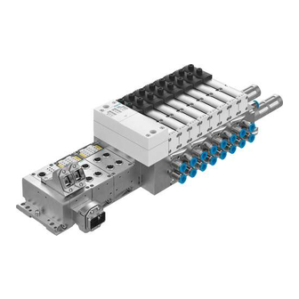
Festo VTSA Series Description
Valve terminal with vtsa pneumatics
Hide thumbs
Also See for VTSA Series:
- Description (267 pages) ,
- Description pneumatics (256 pages) ,
- Manual (176 pages)
Table of Contents
Advertisement
Quick Links
Advertisement
Chapters
Table of Contents

Related Manuals for Festo VTSA Series


Summary of Contents for Festo VTSA Series
- Page 1 VTSA / VTSA−F valve terminal Description VTSA... pneumatics Valve terminal with VTSA pneumatics Type VTSA−44−FB Type VTSA−44−MP... Type VTSA−44−ASI Type VTSA−FB−03E... Type VTSA−F−45−FB... Type VTSA−F−45−MP. Type VTSA−F−45−ASI Description 538 923 en 0905e [743 303]...
- Page 3 ....... . . 538 923 E Festo AG & Co. KG, D 73726 Esslingen, Germany, 2009) Internet: http://www.festo.com E−mail:...
- Page 4 Contents and general safety instructions ® ® CAGE CLAMP CAGE CLAMP is a registered trade mark of WAGO Kontakt technik GmbH, 32385 Minden, Germany Festo P.BE−VTSA−44−EN en 0905e...
-
Page 5: Table Of Contents
........3−8 Festo P.BE−VTSA−44−EN en 0905e... - Page 6 ......... . . 4−15 4.5.2 Operating states of the pneumatic system ....4−16 Festo P.BE−VTSA−44−EN en 0905e...
- Page 7 ............C−1 Festo P.BE−VTSA−44−EN en 0905e...
- Page 8 Contents and general safety instructions Festo P.BE−VTSA−44−EN en 0905e...
-
Page 9: Intended Use
CE marking. Standards and test values, which the product must comply with and meet, can be found in the Technical data" section. The product−relevant EU directives can be found in the declaration of conformity. Festo P.BE−VTSA−44−EN en 0905e... -
Page 10: Target Group
The technical data in this documentation may show values deviating from this. Target group This manual is directed exclusively toward technicians trained in control and automation technology. Service Please consult your local Festo repair service if you have any technical problems. VIII Festo P.BE−VTSA−44−EN en 0905e... -
Page 11: Notes On The Use Of This Manual
M23 round plug, M12 individual connections): Information about the electric/electronic components is included in the documentation supplied with the product. Valve terminal with AS−interface: Information about the electric/electronic components is included in the documentation supplied with the product. Festo P.BE−VTSA−44−EN en 0905e... -
Page 12: Important User Instructions
... means that failure to observe this instruction may result in material damage. The following pictogram marks passages in the text which describe activities with electrostatically sensitive devices: Electrostatically sensitive devices: improper handling can result in damage to components. Festo P.BE−VTSA−44−EN en 0905e... - Page 13 Pictograms Information: Recommendations, tips and references to other sources of information. Accessories: Information on necessary or useful accessories for the Festo product. Environment: Information on the environmentally−friendly use of Festo products. Text designations Bullet points indicate activities that may be carried out in ·...
- Page 14 With two valve positions for 18 mm and 26 mm widths With one valve position for 42 mm (I SO 1) and 52 mm (ISO 2) widths Per valve position with working lines (2) and (4). Manual override Festo P.BE−VTSA−44−EN en 0905e...
- Page 15 Tubing connection Connecting the supply lines (tubing) to the valve terminal Valve Solenoid valve with monostable, impusle or mid−position valve Vertical pressure shut−off Plate on a valve position for cutting off the valve pressure supply plate XIII Festo P.BE−VTSA−44−EN en 0905e...
- Page 16 VTSA valve terminal VTSA (type 44) or VTSA−F (type 45) valve terminal With CPX terminal With FB 21 (type 03) AS−interface With multi−pin node (Sub−D, cage clamp, M23 round plug or IC). Tab. 0/1: Product−specific terms and abbreviations Festo P.BE−VTSA−44−EN en 0905e...
-
Page 17: Overview Of Components
Overview of components Chapter 1 1−1 Festo P.BE−VTSA−44−EN en 0905e... - Page 18 Description of components ....... . 1−9 1−2 Festo P.BE−VTSA−44−EN en 0905e...
- Page 19 Information on the electronics of the VTSA... valve terminal with multi−pin node can be found in the corresponding package insert. Information on the electronics of the VTSA... valve terminal with AS interface can be found in the corresponding package insert. 1−3 Festo P.BE−VTSA−44−EN en 0905e...
-
Page 20: The Vtsa
1. Overview of components The VTSA... valve terminal Festo assists you in solving your automation tasks on the machine level with VTSA... valve terminals. The modular structure of the valve terminal enables you to match it opti mally on your machine or system. -
Page 21: Overview Of Variants
The valves are actuated via the CPX electronics: fieldbus. The valves are actuated via the type 03 field bus. AS−interface The valves are actuated via the AS−interface. Tab. 1/1: Alternative electrical connections of the VTSA... valve terminal with fieldbus 1−5 Festo P.BE−VTSA−44−EN en 0905e... - Page 22 Tab. 1/2: Alternative electrical connections of the VTSA... valve terminal with electric multi−pin The VTSA... valve terminal is available with the following number of valve positions depending on the manifold sub− bases used and the alternative electrical connection (see also 1.1.2 Description of components manifold sub−bases). 1−6 Festo P.BE−VTSA−44−EN en 0905e...
- Page 23 2) If the VTSA is fitted only with these manifold sub−bases (these sub−bases support actuation of two solenoid coils per valve position) 3) Multi−pin node IC with 6 individual connections Tab. 1/4: Number of valve positions for VTSA... with multi−pin plug connections 1−7 Festo P.BE−VTSA−44−EN en 0905e...
- Page 24 4) These manifold sub−bases support actuation of only one solenoid coil per valve position 5) These manifold sub−bases support actuation of two solenoid coils per valve position Tab. 1/5: Number of valve positions for VTSA... with AS−interface 1−8 Festo P.BE−VTSA−44−EN en 0905e...
-
Page 25: Description Of Components
1.1.2 Description of components The VTSA... valve terminal consists of the following pneumatic components: Right end plate 90°−connection plate (optional) Pneumatic supply plates (optional) Manifold sub−base Fig. 1/1: Pneumatic components of the VTSA... valve terminal (1st level) 1−9 Festo P.BE−VTSA−44−EN en 0905e... - Page 26 Cover plate for valve position Vertical pressure shut−off plate (optional) (optional) Valves Vertical pressure supply plate (optional) Exhaust port cover Flow control plate (optional) Soft−start valve Fig. 1/2: Pneumatic components of the VTSA... valve terminal (2nd level) 1−10 Festo P.BE−VTSA−44−EN en 0905e...
- Page 27 The VTSA... valve terminal with FB 21, type 03 consists of the following electric components: Left end plate (type 03): Fieldbus node 21 Pneumatic interface Further optional type 03 modules Fig. 1/4: Electric components of the VTSA... valve terminal with FB 21, type 03 1−11 Festo P.BE−VTSA−44−EN en 0905e...
- Page 28 The VTSA... valve terminal with cage clamp multi−pin node consists of the following electric components: Cover Protective conduit with strain relief Multi−pin node Cage clamp Fig. 1/6: Electric components of the VTSA... valve terminal with cage clamp multi−pin node 1−12 Festo P.BE−VTSA−44−EN en 0905e...
- Page 29 The VTSA... valve terminal with M23 round plug multi−pin node consists of the following electric components: IC connections Multi−pin node Fig. 1/8: Electric components of the VTSA... valve terminal with IC multi−pin node 1−13 Festo P.BE−VTSA−44−EN en 0905e...
- Page 30 (monostable or bistable), 5/3−way mid−position valves, 2x2/2−way valves and standard or reversible 2x3/2−way valves. All 5/2−way valves and 5/3−way mid−position valves can be used in all operating modes: Standard operation Reversible operation Low−pressure operation Vacuum operation 1−14 Festo P.BE−VTSA−44−EN en 0905e...
- Page 31 VSVA−B−T32C−AZD−A1−1T1L means that this valve consists of two, normally closed monostable 3/2−way valves. You can identify the valve function using the following table. In the sales documentation and in the Festo Configurator, the valves are marked with an ID code. Identifier in...
- Page 32 5/3−way valve, normally open from 1 > 2, switching position 14 P53AD−ZD latching 1) Identification in the type code of the control block: VOFA−B26−T52−M...−1C1... Tab. 1/6: Identification of the valve function in the type code 1−16 Festo P.BE−VTSA−44−EN en 0905e...
- Page 33 14. If there is no longer a signal on coil 14, the switching position 14 remains as is, since there is no spring return on control side 12. Switching position 12 is non−latching due to the mechanical spring force. 1−17 Festo P.BE−VTSA−44−EN en 0905e...
- Page 34 When the valve is not switched, duct (1) of the v alve terminal is exhausted via the soft−start valve’s exhaust outlet. The switching point for full operating pressure is set to 4 bars at the factory, but can be changed using an adjusting screw. 1−18 Festo P.BE−VTSA−44−EN en 0905e...
- Page 35 Instructions for combining the soft−start valve, pneu matic supply plate and the right end plate can be found in the VABV−S6−1Q−... assembly instructions. Additional information on the valves can be found in Appendix B. 1−19 Festo P.BE−VTSA−44−EN en 0905e...
- Page 36 Type code VABV−S4−...T1 or VABV−S4−...T2 or VABV−S2−...T1 VABV−S2−...T2 Code on the type plate of the Black dot manifold sub−base Colour of the solenoid coil Black contact Tab. 1/7: Manifold sub−base identification 1−20 Festo P.BE−VTSA−44−EN en 0905e...
- Page 37 A pressure zone separation of pilot ducts (12) and (14) is therefore not possible. You can ascertain the number of pressure zones with which your valve terminal is equipped, by the marking on the seal plate (see figure). 1−21 Festo P.BE−VTSA−44−EN en 0905e...
- Page 38 There are two groups of end plates on VTSA... valve ter minals. For end plates with axial supply connections, the pilot variant is determined by the design. 1−22 Festo P.BE−VTSA−44−EN en 0905e...
- Page 39 2. Size 2: Size 2: 1) For notes on adjusting the pilot air selector or fitting the end plates, see Chapter 3.3.2 Tab. 1/8: Variants of the right end plate 1−23 Festo P.BE−VTSA−44−EN en 0905e...
- Page 40 You can fit further pneumatic components in each location between the manifold sub−base and the valve. This vertical stacking will enable you to implement certain additional ef fects as desired. The following diagram shows the available components: 1−24 Festo P.BE−VTSA−44−EN en 0905e...
- Page 41 VABF...A1G2... Working Type VABV...T1 or connections (2) and (4) turned type VABV...T2 90°. 1) For instructions on installing the vertical stacking components, see Chapter 3 Tab. 1/9: Pneumatic module components of the VTSA... valve terminal 1−25 Festo P.BE−VTSA−44−EN en 0905e...
- Page 42 10 bars. You can identify the vertical stacking components using the following table: In the sales documentation and in the Festo Configurator, the components are marked with an ID code. 1−26...
- Page 43 0.5 to 10 bar R7−...−10 Reversible A pressure regulator plate for port (4), control range 0.5 to 10 bar R5−...−10 Reversible AB pressure regulator plate for ports (2) and (4), control range 0.5 to 10 bar 1−27 Festo P.BE−VTSA−44−EN en 0905e...
- Page 44 The pressure regulating valve is not affected by exhaust ing, since the pressure is regulated upstream of the valve. The pressure regulating valve can always be adjusted because the pressure from the valve terminal is always present. 1−28 Festo P.BE−VTSA−44−EN en 0905e...
- Page 45 (2) of the manifold sub−base. The exhaust is passed via duct (4) to pressure regulating valve A and then via the valve to duct (5). 1−29 Festo P.BE−VTSA−44−EN en 0905e...
- Page 46 1. Overview of components Port (2) (B) Port (4) (A) B pressure regulating valve Manifold sub−base Valve Duct (5) (exhaust) A pressure regulating valve Duct (1) (air) Intermediate plate Duct (3) (exhaust) Fig. 1/11: AB pressure regulating valve 1−30 Festo P.BE−VTSA−44−EN en 0905e...
- Page 47 Exhaust process: Venting occurs in the valve from duct (4) or duct (2) to duct (1) and in the intermediate plate to duct (5) in the intermedi ate plate or duct (3) or the manifold sub−base. 1−31 Festo P.BE−VTSA−44−EN en 0905e...
- Page 48 Port (2) (B) Port (4) (A) B pressure regulating valve Manifold sub−base Valve Duct (5) (exhaust) A pressure regulating valve Duct (1) (air) Intermediate plate Duct (3) (exhaust) Fig. 1/12: Reversible AB pressure regulating valve 1−32 Festo P.BE−VTSA−44−EN en 0905e...
- Page 49 (2) and (4). When fast venting is required. When the pressure regulator must always be adjustable. For instructions on how to install this pressure regulating valve, see Chapter 3.3.6. 1−33 Festo P.BE−VTSA−44−EN en 0905e...
- Page 50 Chapter 3, Section 3.3.2. Vertical pressure supply plate This plate can be used to supply a valve in vertical stacking with an individual operating pressure independently of the operating pressure of the terminal. 1−34 Festo P.BE−VTSA−44−EN en 0905e...
- Page 51 Supply port (1) Operating pressure" Optional MO cover cap, for non−det Work connections (2) and (4), for enting function of MO each valve location Inscription fields Fig. 1/13: Pneumatic connecting, display and operating elements of the VTSA... valve terminal 1−35 Festo P.BE−VTSA−44−EN en 0905e...
- Page 52 Adjusting knob with grid locking valve position (with widths 18 mm and 26 mm, with free−wheel unit) Port (1) (individual operating pressure for one valve position) Fig. 1/14: Operating and connecting elements of the components for vertical stacking 1−36 Festo P.BE−VTSA−44−EN en 0905e...
- Page 53 (non−detenting) Air supply time" flow control screw Electrical terminal for solenoid coil Soft−start valve Port for optional pressure gauge Sensor for sensing the piston position Fig. 1/15: Connecting and operating elements of the soft−start valve 1−37 Festo P.BE−VTSA−44−EN en 0905e...
- Page 54 Yellow LEDs: Signal status display of Red LED: Common error display for the pilot solenoid coils valves Voltage supply connection Earth terminal Fig. 1/16: Electrical connecting, display and operating elements of the VTSA... valve terminal with CPX terminal 1−38 Festo P.BE−VTSA−44−EN en 0905e...
- Page 55 Fig. 1/17: Electrical connecting, display and operating elements of the VTSA... valve terminal with FB 21, type 03 Information on the connecting, display and operating el ements of the VTSA... valve terminal with AS−interface can be found in the corresponding package insert. 1−39 Festo P.BE−VTSA−44−EN en 0905e...
- Page 56 Sub−D multi−pin plug socket with Sub−D connection cable Yellow LEDs: Signal status display of the pilot solenoid coils Inscription panel Earth terminal Fig. 1/18: Electrical connecting and display elements of the VTSA... valve terminal with Sub−D multi−pin node 1−40 Festo P.BE−VTSA−44−EN en 0905e...
- Page 57 Yellow LEDs: Signal status display of necting cable the pilot solenoid coils Terminal strip Protective conduit Inscription panel Fig. 1/19: Electrical connecting and display elements of the VTSA... valve terminal with cage clamp multi−pin node 1−41 Festo P.BE−VTSA−44−EN en 0905e...
- Page 58 Yellow LEDs: Signal status display of the pilot solenoid coils M23 round plug as per CNOMO E03.62.530.N Fig. 1/20: Electrical connecting and display elements of the VTSA... valve terminal with M23 round plug multi−pin node 1−42 Festo P.BE−VTSA−44−EN en 0905e...
- Page 59 VTSA... valve terminal with IC multi−pin node: M12 individual connections (IC) External earth terminal Yellow LEDs: Signal status display of the pilot solenoid coils Fig. 1/21: Electric components of the VTSA... valve terminal with IC multi−pin node 1−43 Festo P.BE−VTSA−44−EN en 0905e...
- Page 60 (AS−i In) Inputs External earth terminal Yellow LEDs: Signal status display of Inscription panel the pilot solenoid coils Fig. 1/22: Electrical connecting and display elements of the VTSA... valve terminal with AS−interface 1−44 Festo P.BE−VTSA−44−EN en 0905e...
- Page 61 Mounting Chapter 2 2−1 Festo P.BE−VTSA−44−EN en 0905e...
- Page 62 ......2−10 Mounting/dismounting the inscription label holder (optional) ... 2−14 Mounting/dismounting the manual override cover caps (optional) ..2−15 2−2 Festo P.BE−VTSA−44−EN en 0905e...
- Page 63 CPX I/O modules or in the additional description of type 03 I/O modules. Information on mounting modules and components or dered at a later stage can be found in the package insert. 2−3 Festo P.BE−VTSA−44−EN en 0905e...
- Page 64 The specified torques must be complied with. Electrostatically sensitive devices. Therefore, do not touch any contact surfaces. Valve terminals with Sub−D multi−pin node: Protect the multi−pin node against humidity, dirt and dust etc. before connecting multi−pin plug socket with cable. 2−4 Festo P.BE−VTSA−44−EN en 0905e...
- Page 65 Tab. 2/1: VTSA... valve terminal mounting methods Note Mount the VTSA... valve terminal so that there is sufficient space for heat dissipation and ensure that the maximum limits for temperatures are observed (see Appendix A, Technical data"). 2−5 Festo P.BE−VTSA−44−EN en 0905e...
- Page 66 Mounting kit type CPA−BG−NRH. This kit contains 2 M4x10 screws and 2 clamping compo nents. For VTSA... valve terminals with CPX terminal: Mounting kit type CPX−CPA−BG−NRH This kit contains 3 M4x10 screws and 3 clamping compo nents. 2−6 Festo P.BE−VTSA−44−EN en 0905e...
- Page 67 35 mm, height 7.5 mm). Make sure there is suffi cient space for connecting the power supply cables and tubing. 3. Fasten the H−rail to the mounting surface at intervals of approx. every 100 mm. 2−7 Festo P.BE−VTSA−44−EN en 0905e...
- Page 68 Fig. 2/1: Mounting the VTSA... valve terminal on an H−rail 7. Secure the VTSA... valve terminal, as with the CPX ter minal, against tilting or sliding by tightening the retaining screw with 1.3 Nm. 2−8 Festo P.BE−VTSA−44−EN en 0905e...
- Page 69 H−rail. 2. Swing the VTSA... valve terminal forwards from the H−rail (see Fig. 2/3, arrow (B)). 3. Lift the valve terminal off the H−rail (see Fig. 2/3, arrow (A)). 2−9 Festo P.BE−VTSA−44−EN en 0905e...
- Page 70 Fig. 2/3: Dismounting the VTSA... valve terminal from the H−rail 2.2.2 Wall mounting / dismounting The following components contain holes for mounting the valve terminal on a wall (see Tab. 2/3). End plates Pneumatic interface Multi−pin node 2−10 Festo P.BE−VTSA−44−EN en 0905e...
- Page 71 Make sure there is sufficient space for connecting the power supply cables and tubing. 2. Drill mounting holes in the mounting surface. 3. Fasten the valve terminal to the mounting surface with M5 or M6 screws of sufficient length. 2−11 Festo P.BE−VTSA−44−EN en 0905e...
- Page 72 VTSA... valve terminal with multi−pin node Multi−pin node: Two M6 screws Right end plate: Two M6 screws 1 Hole for M6 screw Tab. 2/3: Options for mounting the VTSA... valve terminal on a wall 2−12 Festo P.BE−VTSA−44−EN en 0905e...
- Page 73 1. Secure a mounted hanging valve terminal from falling down before you loosen it from the mounting surface. 2. Loosen the mounting screws (see Tab. 2/3). 3. Remove the valve terminal from the mounting surface. 2−13 Festo P.BE−VTSA−44−EN en 0905e...
- Page 74 (see fig.). Dismounting Pull the inscription label holder out of the mounting on the manifold sub−base. Mounting for identification plate holder on the manifold sub−base Inscription label holder Fig. 2/4: Mounting the inscription label holder 2−14 Festo P.BE−VTSA−44−EN en 0905e...
- Page 75 2. Clip the cover caps into the recesses of the manual over rides (see fig.): Manual override cover cap (manual override without function) Manual override cover cap (manual override non−detenting only) Manual override (MO) Fig. 2/5: Mounting the MO cover caps 2−15 Festo P.BE−VTSA−44−EN en 0905e...
- Page 76 Dismounting Proceed as follows: Use a suitable screwdriver to lift the manual override caps · out of the manual overrides (see fig.): Fig. 2/6: Dismounting the manual override caps 2−16 Festo P.BE−VTSA−44−EN en 0905e...
- Page 77 Installation Chapter 3 3−1 Festo P.BE−VTSA−44−EN en 0905e...
- Page 78 ........3−39 3−2 Festo P.BE−VTSA−44−EN en 0905e...
-
Page 79: Installation
I/O modules, etc.) can be found in the correspon ding CPX module descriptions. Detailed instructions for con necting typ 03 modules (fieldbus nodes, I/O modules) can be found in the corresponding descriptions for the type 03 modules. 3−3 Festo P.BE−VTSA−44−EN en 0905e... -
Page 80: Compressed Air Preparation
3.1.2 Operation with lubricated compressed air Operate system equipment with unlubricated compressed air if possible. This is better for the environment. Festo pneu matic valves and actuators have been designed so that, if used as intended, they will not require additional lubrication and will still achieve a long service life. - Page 81 Incorrect additional oil and too much residual oil content in the compressed air will reduce the service life of the valve terminal. Use Festo special oil OFSW−32 or the other oils listed in the Festo catalogue (as per DIN 51524−HLP32, basic viscosity 32 CST at 40 °C).
- Page 82 Another indicator of over−lubrication is the coloration or the condition of the exhaust air silencer. A distinctly yellow col ouring of the filter element or drops of oil on the silencer indi cate that the lubricator setting is too high. 3−6 Festo P.BE−VTSA−44−EN en 0905e...
-
Page 83: General Connection Technology
The components of the valve terminal contain electrostatically sensitive components. The components will be damaged if you touch the contact surfaces of the plug connectors or if you do not observe the handling specifications for electro− statically sensitive devices. 3−7 Festo P.BE−VTSA−44−EN en 0905e... -
Page 84: Installing The Tubing
Secure the hoses with a hose clamp 3. 3. To have a better overview of the system, group the in stalled tubing together with: Tubing straps Multiple hose holders Fig. 3/1: Mounting the tubing connections 3−8 Festo P.BE−VTSA−44−EN en 0905e... - Page 85 1. Label all pneumatic tubing. 2. Depending on connection: Press down the locking ring of the threaded connec− tor 1, e.g. with a screwdriver or Festo QSO releasing tool. Loosen the clamping screw 2 of the threaded connector.
- Page 86 3. Installation Fig. 3/2: Removing the tubing connections 3−10 Festo P.BE−VTSA−44−EN en 0905e...
-
Page 87: Connecting The Vtsa
As per standard ISO 15407−2 and 5599−2, ports (12) and (14) are intended for supplying the valve terminal with external pilot air. The Festo valves for the VTSA... valve terminal require a pilot air supply exclusively via duct (14). In the case of the reversible 2x3/2−way valves from Festo, additional operating pressure is also required at duct (12) for the pneumatic spring. -
Page 88: Pilot Control (Pilot Air Supply)
(duct (14)) within the valve terminal. Exhaust air cannot be expelled via the soft− start valve. An exhaust plate is required for operation in a pressure zone with separated ducts (1) and (3/5). 3−12 Festo P.BE−VTSA−44−EN en 0905e... - Page 89 Set the pilot pressure according to the specifications in · Appendix A, Tab. A/6 or in the diagrams Fig. A/1. Check which pilot variant your valve terminal has been de signed for (see Chapter 1.1.2, section Pilot control (pilot air supply)"). 3−13 Festo P.BE−VTSA−44−EN en 0905e...
- Page 90 The valve terminal may only be operated in positions 3 · and 4 of the selector plate. Otherwise, pilot air 12 may escape at the interface to the valve when the valve is replaced and the pilot pressure could break down. 3−14 Festo P.BE−VTSA−44−EN en 0905e...
- Page 91 14 to control side 12. This is guaran teed with Festo valves. Valves from other manufacturers might have to be additionally supplied with external pilot air via port (12).
- Page 92 Pilot control with external pilot air supply: Supply the external pilot air via port (14) (3). · Note: Valve terminal with soft−start valve: Observe the VABV−S6−1Q−...assem bly instructions. Tab. 3/1: Variants of the right end plate 3−16 Festo P.BE−VTSA−44−EN en 0905e...
- Page 93 Positions 3 and 4 of the selector plate enable the ducted exhaust of the pilot exhaust air and venting air if the valve terminal is not equipped with reversible 2x3/2−way valves from Festo. The seals between the manifold sub−bases and the valves must be mounted in the appropriate position (see Chapter 5.4.1).
-
Page 94: Vtsa
The ports (1) or (3/5) are: For the pressure zone on the outside right: On the right end plate if the valve terminal is equipped with an end plate of type VABE−...R−... or type VABE−...RZ−... 3−18 Festo P.BE−VTSA−44−EN en 0905e... - Page 95 Ports (12) or (14) on the right end plate are for valve ter minals with pilot control by means of external pilot air supply. By mounting an additional supply plate within a pressure zone you can provide additional supply air or extract exhaust air. 3−19 Festo P.BE−VTSA−44−EN en 0905e...
- Page 96 Supply plate of pressure zone 1 Right end plate with port (14) for external pilot air supply Fig. 3/3: Example of VTSA... valve terminal with 3 pressure zones and pilot control via external pilot air supply 3−20 Festo P.BE−VTSA−44−EN en 0905e...
-
Page 97: Reversibly Operated Vtsa
Note If the valve terminal is fitted with reversible 3/2−way · valves (identifier T32F−A, T32N−A, T32W−A), you must operate the valve terminal only when the selector plate is in position 1. 3−21 Festo P.BE−VTSA−44−EN en 0905e... -
Page 98: Operating The Vtsa
1 or 2 (seeTab. 3/2). If this pressure zone is operated reversibly, the valve terminal may only be operated in when the selector plate is in position 1 (see Tab. 3/2). 3−22 Festo P.BE−VTSA−44−EN en 0905e... -
Page 99: Operating The Vtsa
T32F−A, T32N−A, T32W−A) on reversible pressure regulating valves (identifier R5) need not be operated in a separate pressure zone. The reversible pressure regu lating valves supply pressure via duct (1) and vent the exhaust air via ducts (3) and (5). 3−23 Festo P.BE−VTSA−44−EN en 0905e... -
Page 100: Setting The Pressure Regulating Valves
4. Only for pressure regulating valves of widths 18 mm and 26 mm: Turn the adjusting knob longitudinally toward the pres sure regulator plate. 5. Press the adjusting knob in this position into the snap−in locking of the locking level 1. 3−24 Festo P.BE−VTSA−44−EN en 0905e... - Page 101 Fig. 3/4: Setting the pressure regulator plates (widths 18 mm and 26 mm) using the adjusting knob Adjusting knob in the locking level Adjusting knob in the setting level Adjusting knob Fig. 3/5: Setting the pressure regulator plates (widths 42 mm and 52 mm) using the adjusting knob 3−25 Festo P.BE−VTSA−44−EN en 0905e...
- Page 102 (see Flow diagrams of the pressure regulator valve plates" in Appendix A). Adjusting screw, internal hexagon socket (SW 2.0) Fig. 3/6: Setting the pressure regulator plates (widths 18 mm and 26 mm) using the adjusting screw 3−26 Festo P.BE−VTSA−44−EN en 0905e...
-
Page 103: Vacuum/Low Pressure Operation
0.9 ... 3 bar: The pilot control is operated with an external pilot air supply. The valve terminal is fitted with the following valve sub− bases and sometimes has additional pressure zones. 3−27 Festo P.BE−VTSA−44−EN en 0905e... - Page 104 The suction line (line supplied with vacuum) should be equipped with a filter to prevent any contamination from entering the valve. In vacuum operation, the suction line and the pressure line shall be connected via a T−piece for the ejector pulse. 3−28 Festo P.BE−VTSA−44−EN en 0905e...
-
Page 105: Connecting The Pneumatic Lines
It is possible to mount the 90°−connection plate with the exit for the working lines in the direction of the valve base level, but this is not supported by Festo because the desig nation of the ports no longer applies in this direction of mounting. - Page 106 Important information about this can be found in the VABV−S6−1Q−...assembly instructions. 3−30 Festo P.BE−VTSA−44−EN en 0905e...
- Page 107 Ducted exhaust air from (3/5) or (3) G½", ½"NPT Threaded connector in the the valves and (5) exhaust plate Size 1: Threaded connector in the right G½", ½"NPT end plate with axial supply ports Size 2: G¾", ¾"NPT 3−31 Festo P.BE−VTSA−44−EN en 0905e...
- Page 108 Width 18 mm: Threaded connector in the pneu G Á , Á "NPT matic vertical pressure supply Width 26 mm: plate G¼", ¼"NPT Width 42 mm: G Á , Á "NPT Width 52 mm: G½", ½"NPT 3−32 Festo P.BE−VTSA−44−EN en 0905e...
- Page 109 2) The external pilot air is supplied as standard via port (14). 3) Requirement: The valve terminal must be equipped with Festo valves (except reversible 2x3/2−way valves) 4) Note the following if you wish to exhaust the pilot air in a common duct.
- Page 110 3. Installation (3/5) (12) (14) (3/5) (14) (12) (12) Fig. 3/7: Position of the pneumatic ports 3−34 Festo P.BE−VTSA−44−EN en 0905e...
- Page 111 Valve terminal 1 Exhaust tubing Central pilot exhaust tubing Central exhaust tubing 3/5 Valve terminal 2 Pilot air exhaust tubing Fig. 3/8: Centrally ducted exhaust air with non−return valves 3−35 Festo P.BE−VTSA−44−EN en 0905e...
-
Page 112: Connecting The Electric Cables
EMERGENCY STOP (e.g. switching off the operating voltage for the valves and output modules, switching off the com pressed air). 3−36 Festo P.BE−VTSA−44−EN en 0905e... - Page 113 VTSA... valve terminal with FB21 (type 03): · Note the instructions on earthing in Chapter 2 of the FB21 electronics system manual. You can thereby avoid interference from electromagnetic sources and ensure electromagnetic compatibility in ac cordance with EMC directives. 3−37 Festo P.BE−VTSA−44−EN en 0905e...
- Page 114 Valve terminal with M23 Valve terminal with IC multi− clamp multi−pin node round plug multi−pin node pin node Earth terminal Internal earth terminal in the cage clamp multi−pin node Fig. 3/9: Earth terminals of the VTSA... valve terminal 3−38 Festo P.BE−VTSA−44−EN en 0905e...
-
Page 115: Address Assignment Of The Valves
Occupies two addresses per valve position The following assignment applies: Solenoid coil 14 occupies the lower−value address Solenoid coil 12 occupies the higher−value address. Identification features: Colour of the solenoid coil contact housing in the manifold sub−base: Black 3−39 Festo P.BE−VTSA−44−EN en 0905e... - Page 116 Manifold sub−base (width 18 mm or 26 mm) which occupies one address per valve position (identifier: rating plate with black dot) Fig. 3/10: Example: Address assignment of VTSA... valve terminal with 8 valve positions (top view) 3−40 Festo P.BE−VTSA−44−EN en 0905e...
- Page 117 CPX terminal can be found in the manual for the CPX I/O modules. Further instructions on addressing the VTSA... valve terminal with FB21 (type 03) can be found in the corresponding de scription of the fieldbus. 3−41 Festo P.BE−VTSA−44−EN en 0905e...
- Page 118 3. Installation 3−42 Festo P.BE−VTSA−44−EN en 0905e...
- Page 119 Commissioning Chapter 4 4−1 Festo P.BE−VTSA−44−EN en 0905e...
- Page 120 ......... . . 4−15 4.5.2 Operating states of the pneumatic system ....4−16 4−2 Festo P.BE−VTSA−44−EN en 0905e...
-
Page 121: Commissioning
Further information Commissioning the CPX terminal is described in the relevant manual for the CPX field bus node. The commissioning process for the FB21 (type 03) is described in the manual for the FB 21 electronics. 4−3 Festo P.BE−VTSA−44−EN en 0905e... -
Page 122: General Information
Operate the valve terminal with external pilot air accord · ing to the pressure specified in Appendix A, Tab. A/6. The pilot air must be branched in front of the soft−start valve (see figure). 4−4 Festo P.BE−VTSA−44−EN en 0905e... - Page 123 82/84 12/14 12/14 Externally supplied pilot air, branched in front of the on−off valve Soft−start valve of overall supply Fig. 4/1: Example of valve−cylinder combination with gradual pressure build−up of the overall supply 4−5 Festo P.BE−VTSA−44−EN en 0905e...
-
Page 124: Manual Override
Note If you use the VTSA... valve terminal in a dusty environ ment, Festo recommends that you protect the manual overrides with cover caps of type VAMC−S6−CS against dirt and dust when the valve terminal has been commissioned. - Page 125 The assignment of the manual overrides to the solenoid coils is as follows: Manual override for solenoid coils 12 Manual overrides for solenoid coils 14 Fig. 4/2: Position of the manual overrides on the VTSA... valve terminal (top view) 4−7 Festo P.BE−VTSA−44−EN en 0905e...
-
Page 126: Checking The Valves And The Valve/Actuator Combination
PC. Tab. 4/3: Commissioning variants Commissioning the pneumatic components by means of the manual override is described below. Commissioning of the CPX terminal is described in the corre sponding manual for the CPX fieldbus node. 4−8 Festo P.BE−VTSA−44−EN en 0905e... - Page 127 A valve that has been switched by an electric signal cannot be reset by the manual override. The electric signal is dominant in this case. Reset the electric signal before actuating the manual · override. 1. Switch on the compressed air supply. 4−9 Festo P.BE−VTSA−44−EN en 0905e...
- Page 128 If the manual override is in the actuated state, it is not possible to reset the valve to its neutral position with an electric signal. The manual override is dominant in this case. 4. Switch off the compressed air supply after testing the valves. 4−10 Festo P.BE−VTSA−44−EN en 0905e...
- Page 129 Release the plunger (the spring returns to neutral position · resets the plunger of the manual (not with bistable 5/2−way valves override to the initial position). (identifier B52 / D52) Tab. 4/4: Non−detenting actuation of the manual override 4−11 Festo P.BE−VTSA−44−EN en 0905e...
- Page 130 · anti−clockwise direction as far (not with bistable 5/2−way valves (identifier B52 / D52) as possible. Then release the plunger. · Tab. 4/5: Turning with detent actuation of the manual override 4−12 Festo P.BE−VTSA−44−EN en 0905e...
- Page 131 Valve width 42 mm LED and manual override for solenoid Valve width 52 mm coil 14 Valve width 18 mm Fig. 4/3: The assignment of LEDs and manual overrides to the solenoid coils of the VTSA... valve terminal 4−13 Festo P.BE−VTSA−44−EN en 0905e...
- Page 132 (21.6 V to 26.4 V DC or 99 V to 121 V AC) Compressed air supply not OK Pilot exhaust air blocked Servicing required Tab. 4/6: Meaning of the LED display (VTSA... valve terminal with multi−pin node) 4−14 Festo P.BE−VTSA−44−EN en 0905e...
-
Page 133: Troubleshooting
In the case of valve terminals that are oper · ated with external pilot air, check the pilot pressure after switching on again (if necess ary, set according to the operating pressure, see Chapter 3) Servicing required · Tab. 4/7: Pneumatic system malfunctions 4−15 Festo P.BE−VTSA−44−EN en 0905e... -
Page 134: Operating States Of The Pneumatic System
If control signals are present, the pi EMERGENCY STOP lot air must be applied immediately after being switched on with at least the minimum pressure specified in Appendix A, Tab. A/6. Tab. 4/8: Pneumatic operating states 4−16 Festo P.BE−VTSA−44−EN en 0905e... - Page 135 Maintenance and conversion Chapter 5 5−1 Festo P.BE−VTSA−44−EN en 0905e...
- Page 136 ........5−23 5−2 Festo P.BE−VTSA−44−EN en 0905e...
-
Page 137: Maintenance And Conversion
Information on mounting /removing components and on the electrical connections can be found in the FB21 electronics manual. VTSA... valve terminals with multi−pin: Instructions on connecting the electric components can be found in the package insert. 5−3 Festo P.BE−VTSA−44−EN en 0905e... -
Page 138: General Preventive Action
Threaded connections must be mounted free of offset · and mechanical tension. Check the seals for damage (IP 65). · The contact surfaces must be dry and clean (sealing · effect, avoid leakage and contact errors). 5−4 Festo P.BE−VTSA−44−EN en 0905e... -
Page 139: Dismantling The Valve Terminal
Valves Pressure regulating valves Exhaust plates Cover plates Flow control valves Exhaust port cover Soft−start valve Vertical pressure shut−off plates Vertical pressure supply plates Tab. 5/1: Pneumatic components 5−5 Festo P.BE−VTSA−44−EN en 0905e... - Page 140 Pull the sockets away from the individual connections. · Tab. 5/2: Disconnecting the electrical connections Disconnecting the pneumatic connections Disconnecting the pneumatic connections is described in Chapter 3. Dismantling the valve terminal Dismantling the valve terminal is described in Chapter 2. 5−6 Festo P.BE−VTSA−44−EN en 0905e...
-
Page 141: Replacing Valve Terminal Components
Dismounting Proceed as follows: Use a screwdriver with a narrow blade to loosen the · mounting screws and remove the components from the manifold sub−base (see fig.). 5−7 Festo P.BE−VTSA−44−EN en 0905e... - Page 142 Valve width 18 mm (VSVA−...−A2): 1.0 Nm (± 10 %) Valve width 26 mm (VSVA−...−A1): 2.0 Nm (± 10 %) Valve width 42 mm (VSVA−...−D1): 3.0 Nm (± 20 %) Valve width 52 mm (VSVA−...−D2): 6.5 Nm (± 20 %) 5−8 Festo P.BE−VTSA−44−EN en 0905e...
-
Page 143: Replacing/Adding Components For Vertical Stacking
You thereby guarantee free access to the adjusting screws and connections (see Tab. 5/4). 5−9 Festo P.BE−VTSA−44−EN en 0905e... - Page 144 Fig. 5/2: Recommended sequence of valve position components Note Note the following combination possibilities for positioning an exhaust port cover (common exhaust port 3/5) with exhaust silencer next to a valve position with vertical stacking. 5−10 Festo P.BE−VTSA−44−EN en 0905e...
- Page 145 (see Appendix A, Tab. A/6 and Fig. A/1). The combination of reversibly operated valve terminals with the following components for vertical stacking is not permitted: Reversible pressure regulator plates Flow control plates Vertical pressure shut−off plates Vertical pressure supply plates 5−11 Festo P.BE−VTSA−44−EN en 0905e...
- Page 146 1. Check the seals for damage. Replace the seals if they are damaged. 2. Place the new component on the valve position or onto a component already mounted. 3. Fasten the new component. For width across flats of the hexagon socket wrench, see Tab. 5/4. 5−12 Festo P.BE−VTSA−44−EN en 0905e...
- Page 147 Vertical stacking with pressure regulator plate Pos. Width across flats of the hexagon socket wrench Valve width 18 mm 26 mm 42 mm 52 mm Tab. 5/4: Vertical stacking 4. Mount the removed components in the same manner as before. 5−13 Festo P.BE−VTSA−44−EN en 0905e...
-
Page 148: Replace The Exhaust Plate Or The Exhaust Port Cover
The number of manifold sub−bases with which your VTSA... valve terminal can be fitted depends on the manifold sub− bases and the electrical connection variant. Table Tab. 1/4 in Chapter 1 provides an overview. Dismounting Proceed as follows: 5−14 Festo P.BE−VTSA−44−EN en 0905e... - Page 149 Width across flats of the hexagon socket wrench SW4 Fig. 5/3: Position of the screw connectors with example of the right−hand end plate 5. Pull the corresponding component away from the adjac ent component. 5−15 Festo P.BE−VTSA−44−EN en 0905e...
- Page 150 2. Place the seal plate onto the guide pins of the manifold sub−base or of the pneumatic supply plate (for seal plates with duct separation, see Chapter 3.3.3). Manifold sub−base Guide pins Seal plate (optionally with duct separation) Fig. 5/4: Mounting manifold sub−bases 5−16 Festo P.BE−VTSA−44−EN en 0905e...
- Page 151 4. Fit the valve terminal onto the mounting surface (see Chapter 2 Mounting, Wall mounting" or H−rail mount ing"). 5. Then install the pneumatic and electrical connections (see Chapter 3 Installation, Connecting the VTSA... valve terminal"). 5−17 Festo P.BE−VTSA−44−EN en 0905e...
-
Page 152: Converting The Vtsa
2. Use a screwdriver with a narrow blade to loosen the re taining screws for all the valves. Remove the valves from the manifold sub−bases (see Fig. 5/1). 3. Check the exhaust variant for which the VTSA... valve terminal has been constructed. 5−18 Festo P.BE−VTSA−44−EN en 0905e... -
Page 153: Conversion To Internal Or External Pilot Air Supply
5.4.2 Conversion to internal or external pilot air supply Pilot control can be operated with an internal or external pilot air supply, depending on the right end plate (see Chapter 3, Tab. 3/1 and Tab. 3/2). 5−19 Festo P.BE−VTSA−44−EN en 0905e... -
Page 154: Conversion Of The Vtsa
The following ducts can be separated with the sealing plates: Supply duct (1) only Supply duct (1) and exhaust ducts (3) and (5) Exhaust ducts (3) and (5) only 5−20 Festo P.BE−VTSA−44−EN en 0905e... - Page 155 3. Mount the valve terminals onto the mounting surface (see Chapter 2, Section 2.2.1 for H−rail mounting or Sec tion 2.2.2 for wall mounting). 4. Then install the pneumatic and electrical connections (see Chapter 3, Section 3.3). 5−21 Festo P.BE−VTSA−44−EN en 0905e...
- Page 156 Supply plate with port (1) for supplying compressed air to the 2nd pressure zone Supply plate with port (1) for supplying compressed air to the 1st pressure zone Fig. 5/7: Example of VTSA... valve terminal with 3 pressure zones 5−22 Festo P.BE−VTSA−44−EN en 0905e...
- Page 157 Cover plate VABB...−WT Tab. 5/6: Valve position extension Note If a manifold sub−base is inserted between existing mani fold sub−bases, the address assignment of all the valves to the right of the inserted manifold sub−base changes. 5−23 Festo P.BE−VTSA−44−EN en 0905e...
- Page 158 3. Mount the valve terminal onto the mounting surface (see Chapter 2 Mounting, Wall mounting" or H−rail mounting"). 4. Then install the pneumatic and electrical connections (see Chapter 3 Installation, Connecting the VTSA... valve terminal"). 5−24 Festo P.BE−VTSA−44−EN en 0905e...
- Page 159 Technical appendix Appendix A A−1 Festo P.BE−VTSA−44−EN en 0905e...
- Page 160 ........... . A−23 A−2 Festo P.BE−VTSA−44−EN en 0905e...
- Page 161 Operation − 5 ... + 50 Medium − 5 ... + 50 Protection class IP 65 per DIN 60 529 (with cable from Festo accessories) Type 4 as per NEMA Relative air humidity 90 % at 40 Corrosion protection KBK 0 (as per FN940070)
- Page 162 1) Without threaded connectors 2) For widths 18 mm and 26 mm for two valve positions, for widths 42 mm and 52 mm for one valve position Tab. A/2: General technical data for the VTSA... valve terminal (continued) A−4 Festo P.BE−VTSA−44−EN en 0905e...
- Page 163 CPX system. 3) For requirements for severity level 2, see Tab. A/4 4) VTSA... valve terminal with more than one vertical stacking component on a valve position: Severity level 1 Tab. A/3: Vibration and shock A−5 Festo P.BE−VTSA−44−EN en 0905e...
- Page 164 5 shocks per direction 0.35 mm travel at 10−60 Hz; ±30 g for 11 ms −−−−− 5 g acceleration at 60−150 Hz duration, 5 shocks per direction Tab. A/5: Values for vibration and shock as per DIN/IEC68 A−6 Festo P.BE−VTSA−44−EN en 0905e...
- Page 165 All other 6−bar pressure regulating valves: 0,5 ... 6 All other 10−bar pressure regulating valves: 0,5 ... 10 Manual override Non−detenting or turning with detent Tab. A/6: Medium and pressure range of the VTSA... valve terminal A−7 Festo P.BE−VTSA−44−EN en 0905e...
- Page 166 Fig. A/2: Pilot pressure required in the external pilot air supply for 2x2/2− and 2x3/2−way valves (T22CV−A, T32F−A, T32N−A, T32W−A) Note The fittings of the pneumatic ports cause a reduction in the nominal flow rate of the valves. A−8 Festo P.BE−VTSA−44−EN en 0905e...
- Page 167 (M52−A, M52−M, B52, D52) 1100 1350 5/2−way valves (sensor valve) (M52−MZD−...−AP..., M52−MZD−...−AN...) 1100 1350 5/3−way mid−position valves closed (P53C−M) 1000 1350 exhausted, pressurised (P53E−M, P53ED−H, P53U−M) 1000 (700) 1350 (700) exhausted/pressurised (P53AD−H) 700 (700) 700 (700) A−9 Festo P.BE−VTSA−44−EN en 0905e...
- Page 168 Soft−start valve Ventilation Exhaust VABF−S6−1−... 3000 3300 1) Identifier of the valve in the type code 2) Values for the mid−position are quoted in brackets Tab. A/7: Nominal flow rates of valves of type VSVA−B−... A−10 Festo P.BE−VTSA−44−EN en 0905e...
- Page 169 1) Measuring method 0 − 10 %, as per FN 942032 Tab. A/8: Valve switching times, valve type VSVA−B−..., widths 18 mm and 26 mm, nom inal voltage 24 V DC and 110 V AC A−11 Festo P.BE−VTSA−44−EN en 0905e...
- Page 170 23 / 30 1) 2) Measuring method 0 − 10 %, as per FN 942032 Tab. A/9: Valve switching times of valve types VSVA−B−... widths 42 mm and 52 mm, nominal voltage 24 V DC A−12 Festo P.BE−VTSA−44−EN en 0905e...
- Page 171 Tab. A/10: Valve switching times, valve types VSVA−B−... widths 42 mm and 52 mm, nominal voltage 110 V AC Valve switching times, soft−start valve Switching times [ms] Width Identifier in the type code Valve change over −−− VABF−S6−1−P5A4−... Soft−start valve Tab. A/11: Valve switching times, soft−start valve A−13 Festo P.BE−VTSA−44−EN en 0905e...
- Page 172 10 bar P pressure regulating valve in width 18 mm Fig. A/4: Diagram: Flow rate vs. the output pressure of the 10−bar P pressure regulating valve in the widths 18 mm and 26 mm (identifier R1−...−10) A−14 Festo P.BE−VTSA−44−EN en 0905e...
- Page 173 P pressure regulating valve in width 42 mm Flow rate Fig. A/5: Diagram: Flow rate vs. the output pressure of the 6−bar and 10−bar P pressure regulating valve in the widths 42 mm (identifier R1−...) A−15 Festo P.BE−VTSA−44−EN en 0905e...
- Page 174 18 mm Fig. A/7: Diagram: Flow rate vs. the output pressure of the 10−bar A, B and AB pressure regulating valves in the widths 18 mm and 26 mm (identifier R2−...−10, R3−...−10, R4−...−10) A−16 Festo P.BE−VTSA−44−EN en 0905e...
- Page 175 42 mm Flow rate Fig. A/8: Diagram: Flow vs. the output pressure of the 6 bar and 10 bar A, B and AB pressure regulating valves in width 42 mm (identifier R−..., R3−... and R4−...) A−17 Festo P.BE−VTSA−44−EN en 0905e...
- Page 176 18 mm Fig. A/10: Diagram: Flow rate vs. the output pressure for the reversible 10 bar A, B and AB pressure regulating valves in the widths 18 mm and 26 mm (identifier R7−...−10, R6−...−10 and R5−...−10) A−18 Festo P.BE−VTSA−44−EN en 0905e...
- Page 177 26 mm Turns of the adjusting screw Characteristic curve for flow control plate, width 18 mm Fig. A/12: Diagram: Flow vs. flow control, width 18 mm and 26 mm (flow control plate identifier F1B1) A−19 Festo P.BE−VTSA−44−EN en 0905e...
- Page 178 2 to 3 Characteristic curve of the flow control plate, flow from 4 to 5 Turns of the adjusting screw Fig. A/13: Diagram: Flow rate vs. flow control (flow control plate identifier F1B1) A−20 Festo P.BE−VTSA−44−EN en 0905e...
- Page 179 è www.festo.com 1) The VTSA... valve terminal is intended for industrial use. 2) The maximum signal cable length with VTSA... valve terminals with CPX terminal is 10 m Tab. A/12: Technical data for the electric components A−21 Festo P.BE−VTSA−44−EN en 0905e...
- Page 180 2) Manifold sub−base with one valve position each (widths 42 mm and 52 mm) 3) Note: 7 manifold sub−bases not possible as valve position 14 would not be addressable (addresses 27 and 28). Es stehen nur 26 Adressen zur Verfügung. Tab. A/13: Maximum number of possible manifold sub−bases A−22 Festo P.BE−VTSA−44−EN en 0905e...
- Page 181 A. Technical appendix Accessories For accessories, see www.festo.com\catalogue A−23 Festo P.BE−VTSA−44−EN en 0905e...
- Page 182 A. Technical appendix A−24 Festo P.BE−VTSA−44−EN en 0905e...
- Page 183 Supplementary overview of components Appendix B B−1 Festo P.BE−VTSA−44−EN en 0905e...
- Page 184 ..........B−13 B−2 Festo P.BE−VTSA−44−EN en 0905e...
- Page 185 Identifier M52-A; ID code: M Function: – One monostable 5/2-way valve 12/14 – Pneumatic spring return (14) NOTE: The number of addresses which are occupied by this valve depends on the type of manifold sub- base (see Chapter 3.4). Festo P.BE-VTSA-44-EN en 0905e...
- Page 186 – Valve with ID code: SQ: Switching position query via inductive sensor with NPN output NOTE: The number of addresses which are occupied by this valve depends on the type of manifold sub- base (see Chapter 3.4). Tab. B/1: 5/2-way valves Festo P.BE-VTSA-44-EN en 0905e...
- Page 187 – 5/3-way valve – Normally open. 12/14 (14) Identifier P53AD-ZD; ID code: SB (12) Function: – 5/3-way valve – Normally open from 1 > 2 12/14 – Switching position 14 latching (14) Tab. B/2: 5/3-way mid-position valves Festo P.BE-VTSA-44-EN en 0905e...
- Page 188 12, one monostable 3/2−way valve (normally open) 12/14 Pneumatic spring return (14) Identifier T32U−A; ID code: N Function: (14) (12) Two monostable 3/2−way valves Normally open Pneumatic spring return 12/14 (14) Tab. B/3: 2x3/2−way valves B−6 Festo P.BE−VTSA−44−EN en 0905e...
- Page 189 On control side 14, one reversible monostable 3/2−way valve (normally closed) On control side 12, one reversible monostable 3/2−way valve (normally open) 110/114 33/55 (12) Return via pneumatic spring (14) Tab. B/4: Reversible 2x3/2−way valves B−7 Festo P.BE−VTSA−44−EN en 0905e...
- Page 190 1) Note: The 2/2−way valves with ID code VV are to be operated in a separate pressure zone with separate exhaust ducts (3) and (5) if the VTSA/VTSA−F valve terminal is equipped with additional valve functions. Tab. B/5: 2x2/2−way valve B−8 Festo P.BE−VTSA−44−EN en 0905e...
- Page 191 – With external pilot air supply (ID code PM) Type VABF-S6-1-P5A4-...-1N Designs: – Sensor with NPN output – With internal pilot air supply (ID code PO) – With external pilot air supply (ID code PK) Tab. B/6: Soft-start valves Festo P.BE-VTSA-44-EN en 0905e...
- Page 192 Reversible 2x3/2−way valves (identifier T32F−A, T32N−A, T32W−A) need not be operated in a se parate pressure zone if they are combined with these pressure regulating valves. Tab. B/7: Pressure regulator plates for regulating outputs (2) and (4) B−10 Festo P.BE−VTSA−44−EN en 0905e...
- Page 193 3/2−way valve for shutting off the operating pressure (duct (1)) at the valve position. Blocks duct (14) for the valve position. Supplies the valve position with internal pilot Tab. B/9: Vertical pressure supply plate and vertical pressure shut−off plate B−11 Festo P.BE−VTSA−44−EN en 0905e...
- Page 194 Individual electrical connections Control block with ID code: SP: Switching position query via inductive sensor with PNP output Control block with ID code: SN: Switching position query via inductive sensor with NPN output Tab. B/10: Control block B−12 Festo P.BE−VTSA−44−EN en 0905e...
- Page 195 2. Loosen the retaining screws between the pneumatic inter face and the manifold sub−base or pneumatic supply plate of the VTSA... valve terminal in the sequence 1 3 4 2 (see Fig. B/2). 3. Then loosen the retaining screws. B−13 Festo P.BE−VTSA−44−EN en 0905e...
- Page 196 CPX system description. Mounting Proceed as follows: 1. Make sure the seals are not damaged. Replace the seals if they are damaged. 2. Place the seal onto the guide pins of the pneumatic inter face. B−14 Festo P.BE−VTSA−44−EN en 0905e...
- Page 197 Fig. B/3: Fitting the VTSA... valve terminal to the pneumatic interface 3. Push the pneumatic interface together with the pneumatic manifold sub−bases, or the pneumatic supply plate. Make sure that the seal and the components are correctly posi tioned. B−15 Festo P.BE−VTSA−44−EN en 0905e...
- Page 198 VTSA valve terminal with CPX terminal in the CPX system manual in the section on electric components for VTSA valve terminal with FB 21 in the FB 21 (type 03) electronics description B−16 Festo P.BE−VTSA−44−EN en 0905e...
- Page 199 Index Appendix C C−1 Festo P.BE−VTSA−44−EN en 0905e...
- Page 200 ............C−1 C−2 Festo P.BE−VTSA−44−EN en 0905e...
- Page 201 ......1−38 Current consumption ......A−21 C−3 Festo P.BE−VTSA−44−EN en 0905e...
- Page 202 ........C−4 Festo P.BE−VTSA−44−EN en 0905e...
- Page 203 ........1−6 , 1−12 C−5 Festo P.BE−VTSA−44−EN en 0905e...
- Page 204 ........A−7 C−6 Festo P.BE−VTSA−44−EN en 0905e...
- Page 205 ......4−6 Supply plate (pneumatic), removing/mounting ..5−14 C−7 Festo P.BE−VTSA−44−EN en 0905e...
- Page 206 ....1−26 Mounting additional components ....5−9 C−8 Festo P.BE−VTSA−44−EN en 0905e...
- Page 207 ......... 1−4 C−9 Festo P.BE−VTSA−44−EN en 0905e...
- Page 208 C. Index C−10 Festo P.BE−VTSA−44−EN en 0905e...
Need help?
Do you have a question about the VTSA Series and is the answer not in the manual?
Questions and answers