ICP DAS USA UA-5200 Series User Manual
Iiot communication server
Hide thumbs
Also See for UA-5200 Series:
- Quick start (4 pages) ,
- User manual (79 pages) ,
- Quick start (4 pages)

Related Manuals for ICP DAS USA UA-5200 Series


Summary of Contents for ICP DAS USA UA-5200 Series
- Page 1 ICP DAS CO., LTD. UA-5200 Series User Manual IIoT Communication Server UA-5231 UA-5231M UA-5231M-3GWA UA-5231M-4GE UA-5231M-4GC ICP DAS CO., LTD. All Rights Reserved. www.icpdas.com...
- Page 2 Warranty All products manufactured by ICP DAS are under warranty regarding defective materials for a period of one year, starting from the date of delivery to the original purchaser. Warning ICP DAS CO., LTD. assumes no liability for damages consequent to the use of this product. ICP DAS CO., LTD.
-
Page 3: Table Of Contents
UA-5200 Series User Manual V4.3 ICP DAS Table of Contents UA-5200 IIoT Communication Server ..................6 1.1. Introduction ........................6 1.2. Features ........................7 1.3. Functions ........................8 1.4. Specifications ......................10 1.5. Appearance ........................ 13 1.6. Dimensions ......................... 16 Quick Start ........................... - Page 4 UA-5200 Series User Manual V4.3 ICP DAS 4.2.1. Modbus TCP / Azure Connecting ................. 89 4.3. PID ........................... 100 4.3.1. PID Operation ....................101 4.4. APP Message Notify ....................111 4.4.1. IFTTT Condition Trigger (Line, Facebook, Twitter) ..........112 System Setting ........................125 5.1.
- Page 5 UA-5200 Series User Manual V4.3 ICP DAS 8.6. MQTT JSON and Modbus RTU/ASCII Conversion ........... 188 8.7. MQTT JSON and Modbus TCP Conversion .............. 191 Advanced Setting ....................... 194 9.1. PID Operation ......................195 9.2. IFTTT Condition Trigger .................... 200 I/O Status ...........................
-
Page 6: Ua-5200 Iiot Communication Server
UA-5200 series can access regular remote I/O modules or controllers that already widely used in the factory. With the UA-5200 series, it becomes very easy to make things used in the factory to connect to MES, ERP, SCADA and cloud. -
Page 7: Features
UA-5200 Series User Manual V4.3 ICP DAS 1.2. Features OPC UA Server Service MQTT Client Service MQTT Broker Inside ARM CPU, 1.0 GHz 512 MB RAM and 512 MB Flash Linux kernel 3.2.14 OS ... -
Page 8: Functions
UA-5200 Series User Manual V4.3 ICP DAS 1.3. Functions Built-in OPC UA Server Service The built-in OPC UA Server Service is compliable with IEC 62541 Standard and provides functions of Redundancy, Transmission Security Encryption, Active Transmission, Error Detection, Communication Failure Recovery, etc. to connect SCADA or OPC UA Clients. - Page 9 UA-5200 Series User Manual V4.3 ICP DAS Support IFTTT Logic Control and APP Message Notification UA can combine the IFTTT cloud platform functions and send messages over 460 Web APPs (such as Line, Facebook, Twitter, etc.) when the special events occur. The...
-
Page 10: Specifications
UA-5200 Series User Manual V4.3 ICP DAS 1.4. Specifications Model UA-5231 UA-5231M UA-5231M-3GWA UA-5231M-4GE/4GC System Software Linux Kernel 3.2.14 Embedded Service SFTP server, Web server, SSH CPU Module ARM CPU, 1.0 GHz DDR3 SDRAM 512 MB Flash 512 MB FRAM... - Page 11 UA-5200 Series User Manual V4.3 ICP DAS Model UA-5231 UA-5231M UA-5231M-3GWA UA-5231M-4GE/4GC Temperature Storage Temperature -40 ~ +80°C Ambient Relative 10 ~ 90% RH (non-condensing) Humidity Power Input Range +12 ~ +48 V DC Consumption 4.8 W 6.5 W Wireless Communication...
- Page 12 MQTT Client the MQTT protocol. Connect the MQTT Broker to externally read/control the devices MQTT Service supporting other protocols that linking with the UA-5200 series. Compliance with MQTT v3.1.1 protocol. Support MQTT message MQTT Broker distribution management. Recommend to keep the connection number of Client within 400.
-
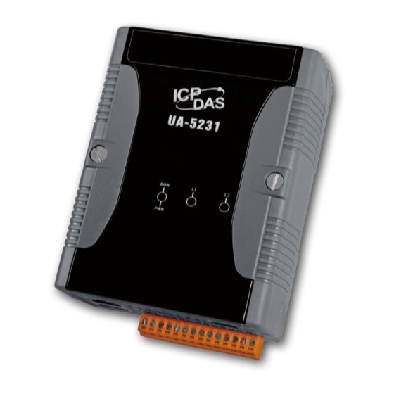
Page 13: Appearance
UA-5200 Series User Manual V4.3 ICP DAS 1.5. Appearance UA-5231... - Page 14 UA-5200 Series User Manual V4.3 ICP DAS UA-5231M...
- Page 15 UA-5200 Series User Manual V4.3 ICP DAS UA-5231M-3GWA / 4GE / 4GC...
-
Page 16: Dimensions
UA-5200 Series User Manual V4.3 ICP DAS 1.6. Dimensions UA-5231 Unit: mm UA-5231M / UA-5231M-3GWA / UA-5231M-4GE / UA-5231M-4GC Unit: mm... -
Page 17: Quick Start
This section describes the hardware wiring and connection for the UA-5200 Controller. 2.1.1. Preparations for Devices In addition to the UA-5200 series controllers (Ex: UA-5231), please prepare the following: Power Supply: +12 ~ +48 VDC (Ex: DP-665) 2. Ethernet Hub or Switch (Ex: NS-205) ... -
Page 18: Network Connection
UA-5200 Series User Manual V4.3 ICP DAS 2.2. Network Connection This section introduces how to connect to the UA-5200 Web User Interface (UA Web UI). The new user or setting the new UA controller is recommended to follow the method in the first session. - Page 19 UA-5200 Series User Manual V4.3 ICP DAS 3. Click【System Setting】【Network Setting】【Network Setting(LAN1)】to change the IP setting by user network. 4. Save the IP setting, restore the PC original IP settings, and type the new IP in the browser as step-2 to login the Web UI of UA-5200. And then configure user’s UA...
-
Page 20: Connection By Utility Searching
UA-5200 Series User Manual V4.3 ICP DAS 2.2.2. Connection by Utility Searching The method of using the UA-5200's factory default settings has described in the Section 2.2.1. If the UA-5200 has a fixed IP and in the same domain as the PC, users can directly enter the IP in the address bar of a web browser and log in to the Web UI of the UA-5200. - Page 21 UA-5200 Series User Manual V4.3 ICP DAS 2. Create a new connection Click “New” to add a connection item and give a name for it. 3. Search the UA-5200 controller Mouse double-click on the name you created (or single-click and then click the...
- Page 22 UA-5200 Series User Manual V4.3 ICP DAS 4. Connect to the UA-5200 controller Click the device name you want to connect to, and then click the “Connect” button. It will connect to the UA-5200 webpage via the default Web browser (IE/Chrome…).
- Page 23 UA-5200 Series User Manual V4.3 ICP DAS 6. Login the Web UI of the UA-5200 controller When login into the web interface, the UA-5200 default home page (the main configuration screen) will be displayed as below, and will automatically read setting of...
-
Page 24: Project Setting Example
UA-5200 Series User Manual V4.3 ICP DAS 2.3. Project Setting Example The screen view after login the UA-5200 Web UI (Web User Interface) is as the following picture. Then can start to setup the UA series controller. If your UA-5200 controller has not connected to the Web UI, please refer to Section 2.1... -
Page 25: A Quick Setup Project Example
UA-5200 Series User Manual V4.3 ICP DAS 2.3.1. A Quick Setup Project Example This example will setup a project for OPC UA and Modbus RTU (Master) communication protocol conversion using the Function Wizard. The devices include a UA-5231 controller and an M-7055D module that wired with RS-485 interface to read/write the Modbus RTU I/O data and need the convert setting. - Page 26 UA-5200 Series User Manual V4.3 ICP DAS After click the【(Master) Modbus RTU / OPC UA】, follow the “Step Box” to complete the 6 steps: (The step with a bold underline means it is the current step.) Step 1. Controller COM Port Setting This step sets up the COM port of the UA series controller to connect with the module and the communication setting.
- Page 27 UA-5200 Series User Manual V4.3 ICP DAS Step 2. Module Setting Click the next step, and enter the Step 2 [Module Setting] of the UI setting. This step is for setting the connected modules. The user can set each module a name...
- Page 28 UA-5200 Series User Manual V4.3 ICP DAS [Module Content Setting] page can set up the module and the Modbus address mapping table: Please set up the addresses mapping with the module I/O channels in the [Modbus Mapping Table Setting]. The system provides 4 Modbus data models (as below) “01”...
- Page 29 UA-5200 Series User Manual V4.3 ICP DAS In this example, the M-7055D has DO and 8 DI channels, please create the table as following pictures of the [Modbus Mapping Table Setting]. After complete the setting, the DO and DI Modbus address settings will show in the [Modbus Mapping Table].
- Page 30 UA-5200 Series User Manual V4.3 ICP DAS Step 3. OPC UA Connection Click the next step, and enter the Step 3 [OPC UA Connection] of the UI setting This step is for setting the IoT platform and the OPC UA connection, e.g. the server name, port, login identity information, etc.
- Page 31 UA-5200 Series User Manual V4.3 ICP DAS Step 4. Enable Converting Module Click the next step, and enter the Step 4 [Enable Converting Module] UI setting This step is for enabling the Modbus RTU / OPC UA conversion. We select the “Modbus RTU / OPC UA” conversion at the beginning, so this step will auto enter the [OPC UA >...
- Page 32 UA-5200 Series User Manual V4.3 ICP DAS Step 5. Save Project The setting of this example is finished now, and then to save the whole project and run the project. So the last two steps will not show setting pages, but show some displays.
-
Page 33: Web Ui Login And Environment Overview
UA-5200 Series User Manual V4.3 ICP DAS 3. Web UI Login and Environment Overview This chapter introduces the ways to login the UA Web User Interface (UI) and the environment of the Web UI of the UA series (IIoT Communication Server), including the version display, system information, function areas, etc. - Page 34 UA-5200 Series User Manual V4.3 ICP DAS After log in the Web UI, the version information is first displayed on the screen. It includes: the version of the install Middleware program, main program and Web Interface (and date). The following picture shows the screen view of the Web UI since Version 2.0.0.
-
Page 35: Web Ui Environment Overview
UA-5200 Series User Manual V4.3 ICP DAS 3.2. Web UI Environment Overview The function setting of the Web UI is including the following areas. The next seven chapters will introduce the settings of the functions and parameters. Here will overview these areas. -
Page 36: Setting Procedures And Steps
UA-5200 Series User Manual V4.3 ICP DAS 3.3. Setting Procedures and Steps Procedures for Project/Function Setting: The function setting procedure for the UA series controllers is to set up from the left to the right of the main menu functions. The “Function Wizard” even provides the “Step Box” for new users to follow the steps and prevent from selecting the wrong function, e.g. -
Page 37: Function Wizard
UA-5200 Series User Manual V4.3 ICP DAS 4. Function Wizard [Function Wizard] at the up-right corner of the Web UI since the version V2.0.0 provides a quick setting “Step Box” suitable for new users to set up the projects or functions. -
Page 38: Module Communication Conversion
UA-5200 Series User Manual V4.3 ICP DAS 4.1. Module Communication Conversion “Module Communication Conversion” of UA series, a very commonly used function, can effectively communicate the IoT devices or systems (e.g. cloud, database…) with I/O data of the module (e.g. Modbus module). This section will introduce the setting steps and the function parameters of the “Module Communication Conversion”. -
Page 39: Modbus / Opc Ua Conversion
UA-5200 Series User Manual V4.3 ICP DAS 4.1.1. Modbus / OPC UA Conversion Modbus / OPC UA Conversion include the conversion of OPC UA and Modbus RTU / TCP / ASCII three protocols. With the OPC UA Service function, the OPC UA Server can read and write the Modbus RTU/TCP/ASCII devices that connected to the controller. - Page 40 UA-5200 Series User Manual V4.3 ICP DAS Convert Setting: Modbus RTU/ASCII and OPC UA Convert Setting: Modbus RTU/ASCII and OPC UA Modbus UA Series Controller Module RS-485 RS-485: ttyO2, ttyO5 COM Port: RS-232 RS-232: ttyO4 RS-485/RS-232 Note: The hardware/network connection methods please see the...
- Page 41 UA-5200 Series User Manual V4.3 ICP DAS Step 1. Controller COM Port Setting This page allows display and set the COM port interface of the controller for the RS-232/RS-485 serial communication. The user can find the default communication values of our I/O modules from the...
- Page 42 UA-5200 Series User Manual V4.3 ICP DAS Step 2. Module Setting Click the next step, and enter the Step 2 [Module Setting] of the UI setting. This page is for setting the communication values with the connected modules. First choose the serial port that connected with the module, and each module can give a name (Default name: Name).
- Page 43 UA-5200 Series User Manual V4.3 ICP DAS [Module Content Setting] page can set up the module and the Modbus address mapping table: Module Content Setting The module number in the module list (Not editable here) Module Name Give a name, e.g. model number or name. Default: Name.
- Page 44 UA-5200 Series User Manual V4.3 ICP DAS The finished Modbus Mapping Table as below is in order of DO, DI, AO and AI. Modbus Mapping Table – Address Setting The “Address Setting” page of the Modbus Mapping Table Address Setting Click can switch to the The “Nickname Setting”...
- Page 45 UA-5200 Series User Manual V4.3 ICP DAS Modbus Mapping Table – Nickname Setting Modbus Coil Status(0x): Mapping to DO Modbus address Mapping Input Status(1x): Mapping to DI Modbus address Table Holding Registers(4x): Mapping to AO Modbus address Input Registers(3x): Mapping to AI Modbus address Table Display Click [Show] to display all fields, click [Hide] to hide some fields.
- Page 46 UA-5200 Series User Manual V4.3 ICP DAS Step 3. OPC UA Connection Click the next step, and enter the Step 3 [OPC UA Connection] of the UI setting. This page is for setting the IoT platform and the OPC UA connection, e.g. the server name, port, login identity information, etc.
- Page 47 UA-5200 Series User Manual V4.3 ICP DAS Step 4. Enable Converting Module Click the next step, and enter the Step 4 [Enable Converting Module] UI setting This step is for enabling the Modbus RTU (or ASCII) / OPC UA conversion.
- Page 48 UA-5200 Series User Manual V4.3 ICP DAS Click [Edit] button cauld enter the “Module Content Setting” page: Convert Setting > OPC UA > Modbus RTU (Master) – Module Content The module number in the module list (Not editable here) Module Name The module name set in the module list (Not editable here) Convert Setting >...
- Page 49 UA-5200 Series User Manual V4.3 ICP DAS Step 5. Save Project The setting of this example is finished now, and then to save the whole project and run the project. So the last two steps will not show setting pages, but show some displays.
-
Page 50: Mqtt / Opc Ua Conversion
UA-5200 Series User Manual V4.3 ICP DAS 4.1.2. MQTT / OPC UA Conversion MQTT / OPC UA Conversion include the conversion of OPC UA and MQTT protocols. With the OPC UA Service function, the OPC UA Server can read and write the MQTT device that connected to the controller. - Page 51 UA-5200 Series User Manual V4.3 ICP DAS Convert Setting: MQTT and OPC UA Convert Setting: MQTT and OPC UA UA Series MQTT Controller Module (DL-302) LAN: Ethernet Port Ethernet Ethernet Port Note: The hardware/network connection methods please see the...
- Page 52 UA-5200 Series User Manual V4.3 ICP DAS Step 1. MQTT Broker Setting The [MQTT Broker Setting] is for setting the IoT platform and the MQTT Broker connection, e.g. the local or remote broker, port, login information, etc. We select the “MQTT / OPC UA” conversion, so this step will auto enter the [IoT Platform Setting >...
- Page 53 UA-5200 Series User Manual V4.3 ICP DAS After creating a new Remote Broker (as below) : MQTT Connection > Remote Broker List Broker Name The name of the remote MQTT Broker. User can define the name, e.g. Broker1. Default: Name.
- Page 54 UA-5200 Series User Manual V4.3 ICP DAS Step 2. Module Setting Click the next step, and enter the Step 2 [Module Setting]. This page is for setting the communication values of the connected modules. The Ethernet port is LAN for connecting with the TCP module, and each module can give a name (Default name: Name).
- Page 55 UA-5200 Series User Manual V4.3 ICP DAS [MQTT Client Setting] page: MQTT Client Setting The module number in the module list (Not editable here) Module Name Give a name, e.g. model number or name. Default: Name. MQTT Check the Broker want to use Local Broker or Remote Broker.
- Page 56 UA-5200 Series User Manual V4.3 ICP DAS [MQTT Variable Table] : MQTT Variable Table Details Click [Show] to display all fields, click [Hide] to hide some fields. Show / Hide The hide fields: Subscribe QoS, Publish QoS and Retain. Remove Table / Check the box in the left of the variable is to select that variable list, and click the “remove”...
- Page 57 UA-5200 Series User Manual V4.3 ICP DAS Step 3. OPC UA Connection Click the next step, and enter the Step 3 [OPC UA Connection] of the UI setting. This page is for setting the IoT platform and the OPC UA connection, e.g. the server name, port, login identity information, etc.
- Page 58 UA-5200 Series User Manual V4.3 ICP DAS Step 4. Enable Converting Module Click the next step, and enter the Step 4 [Enable Converting Module] UI setting This step is for enabling the MQTT / OPC UA conversion. We select the “MQTT / OPC UA” conversion at the beginning, so this step will auto enter the [OPC UA >...
- Page 59 UA-5200 Series User Manual V4.3 ICP DAS Click [Edit] button cauld enter the “Module Content Setting” page: Convert Setting > OPC UA > MQTT – Module Content Setting The module number in the module list (Not editable here) Module Name The module name set in the module list (Not editable here) Convert Setting >...
- Page 60 UA-5200 Series User Manual V4.3 ICP DAS Step 5. Save Project The setting of this example is finished now, and then to save the whole project and run the project. So the last two steps will not show setting pages, but show some displays.
-
Page 61: Modbus / Mqtt Conversion
UA-5200 Series User Manual V4.3 ICP DAS 4.1.3. Modbus / MQTT Conversion Modbus / MQTT Conversion include the conversion of MQTT and Modbus RTU / TCP / ASCII three protocols. With the MQTT Service function, users can set the MQTT client to publish the message to the specified broker or subscribe the topic, and so to read and write the single channel of the Modbus device that connected to the controller. - Page 62 UA-5200 Series User Manual V4.3 ICP DAS This section introduces the Modbus / MQTT conversion through the conversion of Modbus TCP and MQTT protocol. Convert Setting: Modbus TCP and MQTT Convert Setting: Modbus TCP and MQTT UA Series Modbus...
- Page 63 UA-5200 Series User Manual V4.3 ICP DAS Step 7. Module Setting This page is for setting the communication values of the connected modules. The Ethernet port is LAN for connecting with the TCP module, and each module can give a name (Default name: Name). Click [ ] button could add a new module, and then click [Edit] button to configure the module content and the Modbus mapping table.
- Page 64 UA-5200 Series User Manual V4.3 ICP DAS Module Content Setting The module number in the module list (Not editable here) Module Name Give a name, e.g. model number or name. Default: Name. The IP address of the connected module. Default: 0.0.0.0 Port The port number for Modbus TCP.
- Page 65 UA-5200 Series User Manual V4.3 ICP DAS The finished Modbus Mapping Table as below is in order of DO, DI, AO and AI. Modbus Mapping Table – Address Setting The “Address Setting” page of the Modbus Mapping Table Address Setting Click can switch to the The “Nickname Setting”...
- Page 66 UA-5200 Series User Manual V4.3 ICP DAS Modbus Mapping Table – Nickname Setting Modbus Coil Status(0x): Mapping to DO Modbus address Mapping Input Status(1x): Mapping to DI Modbus address Table Holding Registers(4x): Mapping to AO Modbus address Input Registers(3x): Mapping to AI Modbus address Table Display Click [Show] to display all fields, click [Hide] to hide some fields.
- Page 67 UA-5200 Series User Manual V4.3 ICP DAS Step 8. MQTT Broker Setting Click the next step, and enter the Step 2 [MQTT Broker Setting] of the UI setting. This page is for setting the IoT platform and the MQTT Broker connection, e.g. the local or remote broker, port, login information, etc.
- Page 68 UA-5200 Series User Manual V4.3 ICP DAS After creating a new Remote Broker (as below) : MQTT Connection > Remote Broker List Broker Name The name of the remote MQTT Broker. User can define the name, e.g. Broker1. Default: Name.
- Page 69 UA-5200 Series User Manual V4.3 ICP DAS Step 9. Enable Converting Module Click the next step, and enter the Step 3 [Enable Converting Module] UI setting This step is for enabling the module for the Modbus TCP / MQTT conversion.
- Page 70 UA-5200 Series User Manual V4.3 ICP DAS Click [Edit] button cauld enter the “MQTT Client Setting” page: Convert Setting > MQTT > Modbus TCP (Master) – MQTT Client Setting The module number in the module list (Not editable here) The module name set in the module list (Not editable here) Module Name Scan Rate(ms) Set an update frequency for the task data.
- Page 71 UA-5200 Series User Manual V4.3 ICP DAS Convert Setting > MQTT > Modbus TCP (Master) – Publish & Subscribe Details Click [Show] to display all fields, click [Hide] to hide some fields. Name The variable name of the mapping address. (Not editable here) Attribute Display data attribute of the variable.
-
Page 72: Modbus / Mqtt Json Conversion
UA-5200 Series User Manual V4.3 ICP DAS Step 10. Save Project The setting of this example is finished now, and then to save the whole project and run the project. So the last two steps will not show setting pages, but show some displays. - Page 73 UA-5200 Series User Manual V4.3 ICP DAS Modbus / MQTT JSON Conversion include the conversion of MQTT and Modbus RTU / TCP / ASCII three protocols. With the MQTT Service function, users can set the MQTT client to publish the message to the specified broker or subscribe the topic, and combine several messages that converted in JSON format into a group to read and write the multiple channels of the Modbus RTU devices that connected to the controller.
- Page 74 UA-5200 Series User Manual V4.3 ICP DAS Modbus RTU / ASCII 與 MQTT JSON 轉換傳輸: Convert Setting: Modbus RTU/ASCII and MQTT JSON Modbus UA Series Controller Module RS-485 RS-485: ttyO2, ttyO5 COM Port: RS-232 RS-232: ttyO4 RS-485/RS-232 Note: The hardware/network connection methods please see the...
- Page 75 UA-5200 Series User Manual V4.3 ICP DAS This page allows display and set the COM port interface of the controller for the RS-232/RS-485 serial communication. The user can find the default communication values of our I/O modules from the module CD, manual or I/O Module website.
- Page 76 UA-5200 Series User Manual V4.3 ICP DAS Step 2. Module Setting Click the next step, and enter the Step 2 [Module Setting] of the UI setting. This page is for setting the communication values with the connected modules. First choose the serial port that connected with the module, and each module can give a name (Default name: Name).
- Page 77 UA-5200 Series User Manual V4.3 ICP DAS [Module Content Setting] page can set up the module and the Modbus address mapping table: Module Content Setting The module number in the module list (Not editable here) Module Name Give a name, e.g. model number or name. Default: Name.
- Page 78 UA-5200 Series User Manual V4.3 ICP DAS The finished Modbus Mapping Table as below is in order of DO, DI, AO and AI. Modbus Mapping Table – Address Setting The “Address Setting” page of the Modbus Mapping Table Address Setting Click can switch to the The “Nickname Setting”...
- Page 79 UA-5200 Series User Manual V4.3 ICP DAS Modbus Mapping Table – Nickname Setting Modbus Coil Status(0x): Mapping to DO Modbus address Mapping Input Status(1x): Mapping to DI Modbus address Table Holding Registers(4x): Mapping to AO Modbus address Input Registers(3x): Mapping to AI Modbus address Table Display Click [Show] to display all fields, click [Hide] to hide some fields.
- Page 80 UA-5200 Series User Manual V4.3 ICP DAS Step 3. MQTT Broker Setting Click the next step, and enter the Step 3 [MQTT Broker Setting] of the UI setting. This page is for setting the IoT platform and the MQTT Broker connection, e.g. the local or remote broker, port, login information, etc.
- Page 81 UA-5200 Series User Manual V4.3 ICP DAS After creating a new Remote Broker (as below) : MQTT Connection > Remote Broker List Broker Name The name of the remote MQTT Broker. User can define the name, e.g. Broker1. Default: Name.
- Page 82 UA-5200 Series User Manual V4.3 ICP DAS Step 4. MQTT Group Setting Click the next step, and enter the Step 4 [MQTT Group Setting] of the UI setting. This page is for setting the MQTT Group connection, Setting with the MQTT JSON function in the Convert Transmission, It can make the I/O module messages in groups and then mapping to the user-defined publish and subscribe topics.
- Page 83 UA-5200 Series User Manual V4.3 ICP DAS Click [Edit] botton to enter the [MQTT Client Setting] page: IoT Platform Setting > MQTT Group Connection > MQTT Client Setting The group number in the MQTT Client list (Not editable here) Group Name Give a name, e.g.
- Page 84 UA-5200 Series User Manual V4.3 ICP DAS IoT Platform Setting > MQTT Group Connection > MQTT Client Setting – Publish & Subscribe Publish Topic The topic of sending/publishing data message. The publish Qos (Quality of Service) levels. Default: 2 0: Delivering a message at most once.
- Page 85 UA-5200 Series User Manual V4.3 ICP DAS Step 5. Apply Connection & Enable Converting Module Click the next step, and enter the Step 5 [Apply Connection & Enable Converting Module] UI setting. This page is for applying the connection and enabling the converting module.
- Page 86 UA-5200 Series User Manual V4.3 ICP DAS Click [Edit] button cauld enter the “Module Content Setting” page: Convert Setting > MQTT JSON > Modbus RTU (Master) – Module Content Setting The module number in the module list (Not editable here)
- Page 87 UA-5200 Series User Manual V4.3 ICP DAS Step 6. Save Project The setting of this example is finished now, and then to save the whole project and run the project. So the last two steps will not show setting pages, but show some displays.
-
Page 88: Module Connecting To Azure
UA-5200 Series User Manual V4.3 ICP DAS 4.2. Module Connecting to Azure "Module Connecting to Azure" is a common way to integrate IoT devices into the cloud. Many of the applications use MQTT connection to the cloud for the setting is fast and easy. -
Page 89: Modbus Tcp / Azure Connecting
UA-5200 Series User Manual V4.3 ICP DAS 4.2.1. Modbus TCP / Azure Connecting The UA series provides the MQTT function for module to connect to the Microsoft Azure platform and allows users to publish messages to Azure and receive messages from Azure. - Page 90 UA-5200 Series User Manual V4.3 ICP DAS Modbus TCP Module Connecting to Azure Modbus TCP Module Connecting to Azure UA Series Modbus Controller Modbus LAN: Ethernet Port Ethernet Ethernet Port Note: The hardware/network connection methods please see the Chapter 2...
- Page 91 UA-5200 Series User Manual V4.3 ICP DAS Step 1. Module Setting This page is for setting the communication values of the connected modules. The Ethernet port is LAN for connecting with the TCP module, and each module can give a name (Default name: Name). Click [ ] button could add a new module, and then click [Edit] button to configure the module content and the Modbus mapping table.
- Page 92 UA-5200 Series User Manual V4.3 ICP DAS Module Content Setting The module number in the module list (Not editable here) Module Name Give a name, e.g. model number or name. Default: Name. The IP address of the connected module. Default: 0.0.0.0 Port The port number for Modbus TCP.
- Page 93 UA-5200 Series User Manual V4.3 ICP DAS The finished Modbus Mapping Table as below is in order of DO, DI, AO and AI. Modbus Mapping Table – Address Setting The “Address Setting” page of the Modbus Mapping Table Address Setting Click can switch to the The “Nickname Setting”...
- Page 94 UA-5200 Series User Manual V4.3 ICP DAS Modbus Mapping Table – Nickname Setting Modbus Coil Status(0x): Mapping to DO Modbus address Mapping Input Status(1x): Mapping to DI Modbus address Table Holding Registers(4x): Mapping to AO Modbus address Input Registers(3x): Mapping to AI Modbus address Table Display Click [Show] to display all fields, click [Hide] to hide some fields.
- Page 95 UA-5200 Series User Manual V4.3 ICP DAS Step 2. Azure Setting Click the next step, and enter the Step 2 [Azure Setting] of the UI setting. This page is for setting the Microsoft Azure Platform related information of the MQTT Connection in the IoT platform, e.g.
- Page 96 UA-5200 Series User Manual V4.3 ICP DAS MQTT Connection > Microsoft Azure Platform > Azure List > Azure Content Settings Azure Name Azure name. User can define the name. Default: Name. SAS Token Input the SAS Token which you previously registered for the UA controller from Microsoft Azure.
- Page 97 UA-5200 Series User Manual V4.3 ICP DAS Step 3. Apply Connection & Enable Converting Module Click the next step, and enter the Step 3 [Apply Connection & Enable Converting Module] UI setting. This page is for applying the connection and enabling the converting module.
- Page 98 UA-5200 Series User Manual V4.3 ICP DAS Click [Edit] button cauld enter the “Module Content Setting” page: Convert Setting > MQTT JSON > Modbus TCP (Master) Module List –Module Content Setting The module number in the module list (Not editable here)
- Page 99 UA-5200 Series User Manual V4.3 ICP DAS Step 4. Save Project The setting of this example is finished now, and then to save the whole project and run the project. So the last two steps will not show setting pages, but show some displays.
-
Page 100: Pid
UA-5200 Series User Manual V4.3 ICP DAS 4.3. PID PID (Proportional-Integral-Derivative) control is the most widely used in industrial control systems. A regulator which is controlled in accordance with Proportional, Integral and Derivative is called PID control for short, also called PID regulator. When the user cannot fully grasp or measure parameters of the control system, the PID regulator is the best solution. -
Page 101: Pid Operation
UA-5200 Series User Manual V4.3 ICP DAS 4.3.1. PID Operation In the PID Operation function, UA controller collects the module’s data to operate via the feedback loop component of PID control. The controller compares the collected data with a reference value and then uses this difference to calculate a new input value whose purpose is to allow the system data to reach or remain at the reference value. - Page 102 UA-5200 Series User Manual V4.3 ICP DAS Step 1. Controller COM Port Setting This page allows display and set the COM port interface of the controller for the RS-232/RS-485 serial communication. The user can find the default communication values of our I/O modules from the...
- Page 103 UA-5200 Series User Manual V4.3 ICP DAS Step 2. Module Setting Click the next step, and enter the Step 2 [Module Setting] of the UI setting. This page is for setting the communication values with the connected modules. First choose the serial port that connected with the module, and each module can give a name (Default name: Name).
- Page 104 UA-5200 Series User Manual V4.3 ICP DAS [Module Content Setting] page can set up the module and the Modbus address mapping table: Module Content Setting The module number in the module list (Not editable here) Module Name Give a name, e.g. model number or name. Default: Name.
- Page 105 UA-5200 Series User Manual V4.3 ICP DAS The finished Modbus Mapping Table as below is in order of DO, DI, AO and AI. Modbus Mapping Table – Address Setting The “Address Setting” page of the Modbus Mapping Table Address Setting Click can switch to the The “Nickname Setting”...
- Page 106 UA-5200 Series User Manual V4.3 ICP DAS Modbus Mapping Table – Nickname Setting Modbus Coil Status(0x): Mapping to DO Modbus address Mapping Input Status(1x): Mapping to DI Modbus address Table Holding Registers(4x): Mapping to AO Modbus address Input Registers(3x): Mapping to AI Modbus address Table Display Click [Show] to display all fields, click [Hide] to hide some fields.
- Page 107 UA-5200 Series User Manual V4.3 ICP DAS Step 3. PID Operation Click the next step, and enter the Step 3 [PID Operation] of the UI setting. This page is for setting the Task and related parameters of the PID Operation, e.g. I/O module, I/O channels, variables, set point, control mode ….
- Page 108 UA-5200 Series User Manual V4.3 ICP DAS Advanced Setting > PID Operation > Input Item Module Choose a predefined module for input data of the PID. Select the selection type, number and name of the input module. If no option is available, add a new module.
- Page 109 UA-5200 Series User Manual V4.3 ICP DAS Advanced Setting > PID Operation > Output Item Module Choose a predefined module for output data of the PID. Select the type, selection number and name of the input module. If no option is available, add a new module.
- Page 110 UA-5200 Series User Manual V4.3 ICP DAS Step 4. Save Project The setting of this example is finished now, and then to save the whole project and run the project. So the last two steps will not show setting pages, but show some displays.
-
Page 111: App Message Notify
UA-5200 Series User Manual V4.3 ICP DAS 4.4. APP Message Notify The "APP Message Notify" in the UA Function Wizard provides a condition trigger of IFTTT. IFTTT (if this then that) is a cloud service platform that easy to get your apps and devices working together via creating chains of simple conditional statements (applets). -
Page 112: Ifttt Condition Trigger (Line, Facebook, Twitter)
UA-5200 Series User Manual V4.3 ICP DAS 4.4.1. IFTTT Condition Trigger (Line, Facebook, Twitter) The “IFTTT Condition Trigger (Line, Facebook, Twitter)” combines the functions of the UA and IFTTT cloud platform. When the modules occur the special events that setting in the UA condition, it will trigger the IFTTT and send the message to the IFTTT-related cloud services (such as Line, Facebook, Twitter, etc.) - Page 113 UA-5200 Series User Manual V4.3 ICP DAS Step 1. Controller COM Port Setting This page allows display and set the COM port interface of the controller for the serial communication. The user can find the default communication values of our I/O...
- Page 114 UA-5200 Series User Manual V4.3 ICP DAS Step 2. Module Setting Click the next step, and enter the Step 2 [Module Setting] of the UI setting. This page is for setting the communication values with the connected modules. First choose the serial port that connected with the module, and each module can give a name (Default name: Name).
- Page 115 UA-5200 Series User Manual V4.3 ICP DAS [Module Content Setting] page can set up the module and the Modbus address mapping table: Module Content Setting The module number in the module list (Not editable here) Module Name Give a name, e.g. model number or name. Default: Name.
- Page 116 UA-5200 Series User Manual V4.3 ICP DAS The finished Modbus Mapping Table as below is in order of DO, DI, AO and AI. Modbus Mapping Table – Address Setting The “Address Setting” page of the Modbus Mapping Table Address Setting Click can switch to the The “Nickname Setting”...
- Page 117 UA-5200 Series User Manual V4.3 ICP DAS Modbus Mapping Table – Nickname Setting Modbus Coil Status(0x): Mapping to DO Modbus address Mapping Input Status(1x): Mapping to DI Modbus address Table Holding Registers(4x): Mapping to AO Modbus address Input Registers(3x): Mapping to AI Modbus address Table Display Click [Show] to display all fields, click [Hide] to hide some fields.
- Page 118 UA-5200 Series User Manual V4.3 ICP DAS Step 3. IFTTT Condition Trigger Click the next step, and enter the Step 3 [IFTTT Condition Trigger ]. This page is for the APP message related setting, e.g. IFTTT event name, key, trigger condition, I/O variables ….
- Page 119 UA-5200 Series User Manual V4.3 ICP DAS familiar Note: The “Event Name” and “Key” are set in the IFTTT website. If you are not with IFTTT, p lease see the Appendix C for the setting introductions. Advanced Setting > IFTTT Condition Trigger > Content Setting Input the “Event Name”...
- Page 120 UA-5200 Series User Manual V4.3 ICP DAS Condition Trigger Descriptions: The condition trigger method will different depending on the attribute of the selected variable and the trigger will be different. There are two operation styles: and AIO. variable, then Condition is “Status Change”. When detecting the status is (A) If select changed, it will trigger the event and send the assigned message.
- Page 121 UA-5200 Series User Manual V4.3 ICP DAS variable, then Condition is “Value” and can set the “Dead Band”. The (B) If select condition will be triggered and send the message when the detected value exceeds the upper or lower Dead Band. (Below is a CO2 example. Detect per 500 ms) 3.
- Page 122 UA-5200 Series User Manual V4.3 ICP DAS Please refer to the previous Condition Trigger Descriptions to set up your Condition. When complete, click the “Add” button. The setting will show in the Condition Table. Below Table is setting 2 conditions.
- Page 123 UA-5200 Series User Manual V4.3 ICP DAS Step 4. Save Project The setting of this example is finished now, and then to save the whole project and run the project. So the last two steps will not show setting pages, but show some displays.
- Page 124 UA-5200 Series User Manual V4.3 ICP DAS Step 6. I/O Status The last step [ I/O Status ] can show the I/O real time status of the modules. When click the last step, the Step Box will disappear automatically now, and go to the I/O Status screen view.
-
Page 125: System Setting
UA-5200 Series User Manual V4.3 ICP DAS 5. System Setting System Setting is the first item of the Main Menu and the first screen view when login the UA Web UI. The System Setting provides the functions for system management of the UA series controller and displays the version information of the system (Higher-left picture). -
Page 126: Controller Service Setting
UA-5200 Series User Manual V4.3 ICP DAS 5.1. Controller Service Setting Controller Service Setting provides the function to display and set the running status of the controller service about the project, MQTT Broker and DDNS. System Setting > Controller Service Setting > Functional status... -
Page 127: Time Setting
UA-5200 Series User Manual V4.3 ICP DAS 5.2. Time Setting Time Setting provides the function to display and set the date, time and time zone of the controller, including manually, synchronization, etc. Time Setting provides 3 functions: Data and Time Display, NTP Time Synchronization Setting and Set the Time Manually. - Page 128 UA-5200 Series User Manual V4.3 ICP DAS System Setting > Time Setting > Set The Time Manually Time Setting Set the system time of the UA controller by manually. Directly enter the new year/month/date and hour:minute:second. Read The Local Click [Read] can copy the current time of the using computer to the “Time Setting”...
-
Page 129: Network Setting
UA-5200 Series User Manual V4.3 ICP DAS 5.3. Network Setting Network Setting provides the function to display and set the network settings, including IP address, host controller, DDNS, etc. System Setting > Network Setting > Network Setting (LAN1) Specify an IP address: It's the fixed IP mode. Users input the values Connection in the fields of IP, Mask and Gateway according to customer's network. - Page 130 UA-5200 Series User Manual V4.3 ICP DAS System Setting > Network Setting > Dynamic DNS Setting Service Select the company of the DDNS service. Default: NO-IP. Provider Supports: NO-IP, ChangeIP.com, DynDNS, FreeDNS. *Username Set up the login user name. The star * means the field cannot be null.
- Page 131 UA-5200 Series User Manual V4.3 ICP DAS 1. This setting item only appears on the mobile model of UA controller. 2. In order to complete the connection to the Mobile Network, please disable the PIN code setting of the SIM card used in UA.
- Page 132 UA-5200 Series User Manual V4.3 ICP DAS System Setting > Network Setting > Network Setting(Mobile Network) If check the “Enable” box, it will enable the UA controller to complete Automatic Connection the Mobile Network connection automatically when power on UA When Power On controller.
-
Page 133: Account Setting
UA-5200 Series User Manual V4.3 ICP DAS 5.4. Account Setting Account Setting provides the function to set the login username and password of the UA-5200’s web UI. The factory default username and password of the UA Web UI: root / root. The detail... -
Page 134: Boot
UA-5200 Series User Manual V4.3 ICP DAS 5.5. Boot Boot function provides the function to reboot the UA series controller, and enable the function to run the project, MQTT broker or DDNS at startup. System Setting > Boot > Restart Click “Reboot”... -
Page 135: Com Port Interface Setting
UA-5200 Series User Manual V4.3 ICP DAS 5.6. COM Port Interface Setting COM Port Interface Setting allows display and set the COM port interface of the UA series controller for the RS-232/RS-485 serial communication. System Setting > COM Port Interface Setting > COM Port Interface Setting Page Serial Port Choose the serial port of UA controller that links with the I/O module. -
Page 136: Module Setting
UA-5200 Series User Manual V4.3 ICP DAS 6. Module Setting Module Setting is the second item of the Main Menu. The Module Setting provides the functions for UA series controller to connect the remote Modbus Slave module (including the Modbus RTU/TCP/ASCII module) and the remote MQTT module. -
Page 137: Modbus Rtu (Master)
UA-5200 Series User Manual V4.3 ICP DAS 6.1. Modbus RTU (Master) This setting is for UA Controller connecting the remote Modbus RTU Slave module. This page is for setting the communication values with the connected modules. First choose the serial port that connected with the module, and each module can give a name (Default name: Name). - Page 138 UA-5200 Series User Manual V4.3 ICP DAS The function items and setting parameters of the [Modbus RTU Module List]: Module Setting > Modbus - RTU Module (Master) > Modbus RTU Module List Serial Port Choose the serial port of UA controller that links with the I/O module.
- Page 139 UA-5200 Series User Manual V4.3 ICP DAS Click [Edit] button to enter the “Module Content Setting” page. Module Content Setting The module number in the module list (Not editable here) Module Name Give a name, e.g. model number or name. Default: Name.
- Page 140 UA-5200 Series User Manual V4.3 ICP DAS The finished Modbus Mapping Table as below is in order of DO, DI, AO and AI. Modbus Mapping Table – Address Setting The “Address Setting” page of the Modbus Mapping Table Address Setting Nickname Setting Click can switch to the The “Nickname Setting”...
- Page 141 UA-5200 Series User Manual V4.3 ICP DAS Modbus Mapping Table – Nickname Setting Modbus Mapping Coil Status(0x): Mapping to DO Modbus address Table Input Status(1x): Mapping to DI Modbus address Holding Registers(4x): Mapping to AO Modbus address Input Registers(3x): Mapping to AI Modbus address Table Display Click [Show] to display all fields, click [Hide] to hide some fields.
-
Page 142: Modbus Tcp (Master)
UA-5200 Series User Manual V4.3 ICP DAS 6.2. Modbus TCP (Master) This setting is for UA Controller connecting the remote Modbus TCP Slave module. This page is for setting the communication values with the connected modules. First choose the Ethernet LAN port that connected with the module, and each module can give a name (Default name: Name). - Page 143 UA-5200 Series User Manual V4.3 ICP DAS Module Setting > Modbus - RTU Module (Master) > Modbus RTU Module List Choose the LAN port of UA controller that links with the TCP module. UA-52xx has one LAN port; the coming UA-2xxx has 2 LAN ports.
- Page 144 UA-5200 Series User Manual V4.3 ICP DAS Module Content Setting The module number in the module list (Not editable here) Module Name Give a name, e.g. model number or name. Default: Name. The IP address of the connected module. Default: 0.0.0.0 Port The port number for Modbus TCP.
- Page 145 UA-5200 Series User Manual V4.3 ICP DAS The finished Modbus Mapping Table as below is in order of DO, DI, AO and AI. Modbus Mapping Table – Address Setting The “Address Setting” page of the Modbus Mapping Table Address Setting Nickname Setting Click can switch to the The “Nickname Setting”...
- Page 146 UA-5200 Series User Manual V4.3 ICP DAS Modbus Mapping Table – Nickname Setting Modbus Mapping Coil Status(0x): Mapping to DO Modbus address Table Input Status(1x): Mapping to DI Modbus address Holding Registers(4x): Mapping to AO Modbus address Input Registers(3x): Mapping to AI Modbus address Table Display Click [Show] to display all fields, click [Hide] to hide some fields.
-
Page 147: Modbus Ascii (Master)
UA-5200 Series User Manual V4.3 ICP DAS 6.3. Modbus ASCII (Master) This setting is for UA Controller connecting the remote Modbus ASCII Slave module. This page is for setting the communication values with the connected modules. First choose the serial port that connected with the module, and each module can give a name (Default name: Name). - Page 148 UA-5200 Series User Manual V4.3 ICP DAS The function items and setting parameters of the [Modbus ASCII Module List]: Module Setting > Modbus - ASCII Module (Master) > Modbus ASCII Module List Serial Port Choose the serial port of UA controller that links with the I/O module.
- Page 149 UA-5200 Series User Manual V4.3 ICP DAS Click [Edit] button to enter the “Module Content Setting” page. Module Content Setting The module number in the module list (Not editable here) Module Name Give a name, e.g. model number or name. Default: Name.
- Page 150 UA-5200 Series User Manual V4.3 ICP DAS The finished Modbus Mapping Table as below is in order of DO, DI, AO and AI. Modbus Mapping Table – Address Setting The “Address Setting” page of the Modbus Mapping Table Address Setting Nickname Setting Click can switch to the The “Nickname Setting”...
- Page 151 UA-5200 Series User Manual V4.3 ICP DAS Modbus Mapping Table – Nickname Setting Modbus Mapping Coil Status(0x): Mapping to DO Modbus address Table Input Status(1x): Mapping to DI Modbus address Holding Registers(4x): Mapping to AO Modbus address Input Registers(3x): Mapping to AI Modbus address Table Display Click [Show] to display all fields, click [Hide] to hide some fields.
-
Page 152: Mqtt Module
UA-5200 Series User Manual V4.3 ICP DAS 6.4. MQTT Module This setting is for UA Controller connecting the remote MQTT module. This page is for setting the communication values with the connected modules. First choose the Ethernet LAN port that connected with the module, and each module can give a name (Default name: Name). - Page 153 UA-5200 Series User Manual V4.3 ICP DAS The function items and setting parameters of the [MQTT Module List]: Module Setting > MQTT - MQTT Module > MQTT Module List Choose the LAN port of UA controller that links with the MQTT module.
- Page 154 UA-5200 Series User Manual V4.3 ICP DAS [MQTT Client Setting] page: MQTT Client Setting The module number in the module list (Not editable here) Module Name Give a name, e.g. model number or name. Default: Name. MQTT Check the Broker want to use Local Broker or Remote Broker.
- Page 155 UA-5200 Series User Manual V4.3 ICP DAS [MQTT Variable Table] : MQTT Variable Table Details Click [Show] to display all fields, click [Hide] to hide some fields. Show / Hide The hide fields: Subscribe QoS, Publish QoS and Retain. Remove Table / Check the box in the left of the variable is to select that variable list, and click the “remove”...
-
Page 156: Iot Platform Setting
UA-5200 Series User Manual V4.3 ICP DAS 7. IoT Platform Setting IoT Platform Setting is the third item of the Main Menu. It manages the interaction of the UA series connecting with the host computer in the Internet of Things. It provides OPC UA and MQTT protocols connection services via the Ethernet interface for data transmission. -
Page 157: Mqtt Local Broker
UA-5200 Series User Manual V4.3 ICP DAS 7.1. MQTT Local Broker UA series controller built-in MQTT Broker that compliance with MQTT v3.1.1 protocol and supporting MQTT message distribution management. When using MQTT communication, there is no need to build a new Broker system. -
Page 158: Mqtt Remote Broker
UA-5200 Series User Manual V4.3 ICP DAS 7.2. MQTT Remote Broker UA series controller built-in MQTT Broker(See Section 7.1), but when users want to use the external MQTT Broker, UA system also provides the settings to connect and publish/subscript messages with the MQTT Remote Broker. - Page 159 UA-5200 Series User Manual V4.3 ICP DAS MQTT Connection > Remote Broker > Remote Broker List Broker Name MQTT Remote Broker name. User can give a new name, e.g. Broker1. Default: Name. Click to add a list of remote Broker.
- Page 160 UA-5200 Series User Manual V4.3 ICP DAS MQTT Connection > Remote Broker List > Broker Content Settings Broker Name The name of the remote MQTT Broker. User can define a new name. Set the IP address or domain name of the Remote MQTT Broker.
-
Page 161: Mqtt Group Connection
UA-5200 Series User Manual V4.3 ICP DAS 7.3. MQTT Group Connection This function can set up the MQTT connection with local and remote brokers. Setting with the MQTT JSON function in the Convert Setting, It can make the I/O module messages in groups and then mapping to the user-defined publish and subscribe topics. - Page 162 UA-5200 Series User Manual V4.3 ICP DAS IoT Platform Setting > MQTT Connection > MQTT Connection Group Name List Group Name MQTT connection group name. User can give a new name, e.g. Group1. Default: Name. Click to add a list of MQTT connection group.
- Page 163 UA-5200 Series User Manual V4.3 ICP DAS IoT Platform Setting > MQTT Connection > MQTT Client Setting The MQTT Client Number. (Un-editable) Group Name The name of the Group. User can define a new name. Scan Rate(ms) Set an update frequency for the data. Unit: ms. Default: 1000 ms.
- Page 164 UA-5200 Series User Manual V4.3 ICP DAS IoT Platform Setting > MQTT Connection > MQTT Client Setting – Publish & Subscribe Publish Topic The topic of sending/publishing data message. The publish Qos (Quality of Service) levels. Default: 2. 0: Delivering a message at most once.
-
Page 165: Mqtt Connection - Microsoft Azure Platform
UA-5200 Series User Manual V4.3 ICP DAS 7.4. MQTT Connection - Microsoft Azure Platform Microsoft Azure Platform is a common platform to integrate IoT devices into the cloud. Many of the applications use MQTT connection to the cloud for the setting is fast and easy. - Page 166 UA-5200 Series User Manual V4.3 ICP DAS IoT Platform Setting > MQTT Connection > Microsoft Azure Platform > Azure List Azure Name Azure name. User can give a new name1. Default: Name. Click to add a list of Azure. After adding a list of the Azure: IoT Platform Setting >...
- Page 167 UA-5200 Series User Manual V4.3 ICP DAS IoT Platform Setting > MQTT Connection > Microsoft Azure Platform > Azure Content Settings Azure Name Azure name. User can define the name. Default: Name. SAS Token Input the SAS Token which you previously registered for the UA controller from Microsoft Azure.
-
Page 168: Opc Ua Connection - Local Server
UA-5200 Series User Manual V4.3 ICP DAS 7.5. OPC UA Connection - Local Server UA series controller built-in OPC UA Server service can integrate the I/O products and the third-party devices, import their data to the back-end SCADA management system or the big-data analysis/decision system, to satisfy the reliability, interoperability and security needs of the Industrial 4.0 automation system. -
Page 169: Convert Setting
UA-5200 Series User Manual V4.3 ICP DAS 8. Convert Setting Convert Setting is the fourth item of the Main Menu for the communication conversion. The Convert Setting has 9 sub-menu items in 3 protocol types including OPC UA, MQTT and MQTT JSON. And each protocol type has 3 convert settings items for conversion with the Modbus RTU/TCP/ASCII (Master) protocols and the function descriptions are listed on the page of the Main Menu. - Page 170 UA-5200 Series User Manual V4.3 ICP DAS The settings of Modbus RTU/ASCII are the same. Here will introduce them together. Use OPC UA Service to convert with Modbus RTU/ASCII protocol. (8.1) OPC UA Use OPC UA Service to convert with Modbus TCP protocol. (8.2) Use OPC UA Service to convert with MQTT protocol.
-
Page 171: Opc Ua And Modbus Rtu/Ascii Conversion
UA-5200 Series User Manual V4.3 ICP DAS 8.1. OPC UA and Modbus RTU/ASCII Conversion This page provides OPC UA and Modbus RTU/ASCII (Master) communication protocol conversion. With this function, the OPC UA Server can read and write the Modbus RTU / ASCII device that connected to the controller. - Page 172 UA-5200 Series User Manual V4.3 ICP DAS When entering the menu [Convert Setting] and the sub-menu [OPC UA] > Modbus RTU (Master) or Modbus ASCII (Master), the Modbus RTU/ASCII modules preset in the [Module Setting] will show up in the Module List. (Refer to Chapter 6 for the Module Setting.) Convert Setting >...
- Page 173 UA-5200 Series User Manual V4.3 ICP DAS The “Module Content Setting” page after clicking the [Edit] button: Convert Setting > OPC UA > Modbus RTU (Master) – Module Content The module number in the module list (Not editable here) Module Name The module name set in the module list (Not editable here) Convert Setting >...
-
Page 174: Opc Ua And Modbus Tcp Conversion
UA-5200 Series User Manual V4.3 ICP DAS 8.2. OPC UA and Modbus TCP Conversion This page provides OPC UA and Modbus TCP (Master) communication protocol conversion. With this function, the OPC UA Server can read and write the Modbus TCP device that connected to the controller. - Page 175 UA-5200 Series User Manual V4.3 ICP DAS When entering the menu [Convert Setting] and the sub-menu [OPC UA] > Modbus RTU (Master) or Modbus ASCII (Master), the Modbus RTU/ASCII modules preset in the [Module Setting] will show up in the Module List. (Refer to Chapter 6 for the Module Setting.) Convert Setting >...
- Page 176 UA-5200 Series User Manual V4.3 ICP DAS The “Module Content Setting” page after clicking the [Edit] button: Convert Setting > OPC UA > Modbus TCP (Master) – Module Content The module number in the module list (Not editable here) Module Name The module name set in the module list (Not editable here) Convert Setting >...
-
Page 177: Opc Ua And Mqtt Conversion
UA-5200 Series User Manual V4.3 ICP DAS 8.3. OPC UA and MQTT Conversion This page provides OPC UA and MQTT communication protocol conversion. With this function, the OPC UA Server can read and write the MQTT device that connected to the controller. - Page 178 UA-5200 Series User Manual V4.3 ICP DAS When entering the menu [Convert Setting] and the sub-menu [OPC UA] > MQTT, the MQTT modules preset in the [Module Setting] will show up in the Module List. (Refer to Chapter 6 for the Module Setting.) Convert Setting >...
- Page 179 UA-5200 Series User Manual V4.3 ICP DAS [Module Content Setting] page: Convert Setting > OPC UA > MQTT - MQTT Module List > Module Content Setting The module number in the module list (Not editable here) Module Name Give a name, e.g. model number or name. Default: Name.
-
Page 180: Mqtt And Modbus Rtu/Ascii Conversion
UA-5200 Series User Manual V4.3 ICP DAS 8.4. MQTT and Modbus RTU/ASCII Conversion This page provides MQTT and Modbus RTU/ASCII (Master) communication protocol conversion. With the MQTT Service function, users can set the MQTT client to publish the message to the specified broker or subscribe the topic, and so to read and write the single channel of the Modbus device that connected to the controller. - Page 181 UA-5200 Series User Manual V4.3 ICP DAS When entering the menu [Convert Setting] and the sub-menu [MQTT] > Modbus RTU (Master) or Modbus ASCII (Master), the Modbus RTU/ASCII modules preset in the [Module Setting] will show up in the Module List. (Refer to Chapter 6 for the Module Setting.) Convert Setting >...
- Page 182 UA-5200 Series User Manual V4.3 ICP DAS The “MQTT Client Setting” page after clicking the [Edit] button: Convert Setting > MQTT > Modbus RTU (Master) – MQTT Client Setting The module number in the module list (Un-editable) The module name set in the module list (Not editable here) Module Name Set an update frequency for the task data.
- Page 183 UA-5200 Series User Manual V4.3 ICP DAS Convert Setting > MQTT > Modbus RTU (Master) – Publish & Subscribe Details Click [Show] to display all fields, click [Hide] to hide some fields. Name The variable name of the mapping address. (Not editable here) Attribute Display data attribute of the variable.
-
Page 184: Mqtt And Modbus Tcp Conversion
UA-5200 Series User Manual V4.3 ICP DAS 8.5. MQTT and Modbus TCP Conversion This page provides MQTT and Modbus TCP (Master) communication protocol conversion. With the MQTT Service function, users can set the MQTT client to publish the message to the specified broker or subscribe the topic, and so to read and write the single channel of the Modbus device that connected to the controller. - Page 185 UA-5200 Series User Manual V4.3 ICP DAS When entering the menu [Convert Setting] and the sub-menu [MQTT] > Modbus TCP (Master), the Modbus TCP modules preset in the [Module Setting] will show up in the Module List. (Refer to Chapter 6 for the Module Setting.) Convert Setting >...
- Page 186 UA-5200 Series User Manual V4.3 ICP DAS The “MQTT Client Setting” page after clicking the [Edit] button: Convert Setting > MQTT > Modbus TCP (Master) – MQTT Client Setting The module number in the module list (Un-editable) The module name set in the module list (Not editable here) Module Name Set an update frequency for the task data.
- Page 187 UA-5200 Series User Manual V4.3 ICP DAS Convert Setting > MQTT > Modbus TCP (Master) – Publish & Subscribe Details Click [Show] to display all fields, click [Hide] to hide some fields. Name The variable name of the mapping address. (Not editable here) Attribute Display data attribute of the variable.
-
Page 188: Mqtt Json And Modbus Rtu/Ascii Conversion
UA-5200 Series User Manual V4.3 ICP DAS 8.6. MQTT JSON and Modbus RTU/ASCII Conversion This page provides MQTT JSON and Modbus RTU/ASCII (Master) communication protocol conversion. With the MQTT Service function, users can set the MQTT client to publish the message to the specified broker or subscribe the topic, and combine several messages that converted in JSON format into a group to read and write the multiple channels of the Modbus RTU/ASCII devices that connected to the controller. - Page 189 UA-5200 Series User Manual V4.3 ICP DAS When entering the menu [Convert Setting] and the sub-menu [MQTT JSON] > Modbus RTU or Modbus ASCII (Master), the Modbus RTU/ASCII modules preset in the [Module Setting] will show up in the Module List. (Refer to Chapter 6 for the Module Setting.) Convert Setting >...
- Page 190 UA-5200 Series User Manual V4.3 ICP DAS Convert Setting > MQTT JSON > Modbus RTU (Master) – Module Content Setting The module number in the module list (Not editable here) Module Name The module name set in the module list (Not editable here) Convert Setting >...
-
Page 191: Mqtt Json And Modbus Tcp Conversion
UA-5200 Series User Manual V4.3 ICP DAS 8.7. MQTT JSON and Modbus TCP Conversion This page provides MQTT JSON and Modbus TCP (Master) communication protocol conversion. With the MQTT Service function, users can set the MQTT client to publish the... - Page 192 UA-5200 Series User Manual V4.3 ICP DAS When entering the menu [Convert Setting] and the sub-menu [MQTT JSON] > Modbus TCP (Master), the Modbus TCP modules preset in the [Module Setting] will show up in the Module List. (Refer to Chapter 6 for the Module Setting.) Convert Setting >...
- Page 193 UA-5200 Series User Manual V4.3 ICP DAS Convert Setting > MQTT JSON > Modbus TCP (Master) – Module Content Setting The module number in the module list (Not editable here) Module Name The module name set in the module list (Not editable here) Convert Setting >...
-
Page 194: Advanced Setting
UA-5200 Series User Manual V4.3 ICP DAS 9. Advanced Setting Advanced Setting is the fifth (5 ) item of the Main Menu, mainly to provide advanced monitoring and control related settings. Advanced Setting provides virtual device function or cloud service function. The description is listed on the page of the Main Menu. -
Page 195: Pid Operation
UA-5200 Series User Manual V4.3 ICP DAS 9.1. PID Operation This page is about the virtual device function to allow users to simulate various devices with the real I/O by using the tuning function of PID operation. PID (Proportional-Integral-Derivative) control is the most widely used in industrial control systems. - Page 196 UA-5200 Series User Manual V4.3 ICP DAS PID Operation Solution Example: In the PID Operation function, UA controller collects the module’s data to operate via the feedback loop component of PID control. The controller compares the collected data with a reference value and then uses this difference to calculate a new input value whose purpose is to allow the system data to reach or remain at the reference value.
- Page 197 UA-5200 Series User Manual V4.3 ICP DAS Advanced Setting > PID Operation > PID List PID Name PID name, user can define, e.g. Task1. Default: Task. Click to add a new PID Task. Edit / Remove Click [Edit] can set the PID content.
- Page 198 UA-5200 Series User Manual V4.3 ICP DAS Advanced Setting > PID Operation > Input Item Module Choose a predefined module for input data of the PID. Select the selection type, number and name of the input module. If no option is available, add a new module.
- Page 199 UA-5200 Series User Manual V4.3 ICP DAS Advanced Setting > PID Operation > Output Item Module Choose a predefined module for output data of the PID. Select the type, selection number and name of the input module. If no option is available, add a new module.
-
Page 200: Ifttt Condition Trigger
UA-5200 Series User Manual V4.3 ICP DAS 9.2. IFTTT Condition Trigger This page is about use the IFTTT cloud platform function. Combine with the IFTTT Condition Trigger function, when the special events occur, the users can send messages to IFTTT-related cloud services (such as Line, Facebook, Twitter, etc.). - Page 201 UA-5200 Series User Manual V4.3 ICP DAS The settings for sending the message to the APP with the "IFTTT Condition Trigger (Line, Facebook, Twitter)" function includes two parts: 3. UA Web Interface Setting: In the UA Web HMI, set up the UA controller, modules, IFTTT trigger conditions, the condition variable table, and the IFTTT event connection.
- Page 202 UA-5200 Series User Manual V4.3 ICP DAS Advanced Setting > IFTTT Condition Trigger > FTTT Condition Trigger List Add Message Click to add a new IFTTT message. After setting, an IFTTT condition trigger list will show on the bottom, includes left box, event name, key and status.
- Page 203 UA-5200 Series User Manual V4.3 ICP DAS The condition setting field may different depending on the selected variable attribute. Advanced Setting > IFTTT Condition Trigger > Condition Setting Module Select the module and variable for the condition trigger. Variables Module Type: select the module type, Modbus RTU/TCP/ASCII…...
- Page 204 UA-5200 Series User Manual V4.3 ICP DAS Condition Trigger Descriptions: The condition trigger method will different depending on the attribute of the selected variable and the trigger will be different. There are two operation styles: and AIO. variable, then Condition is “Status Change”. When detecting the status is (A) If select changed, it will trigger the event and send the assigned message.
- Page 205 UA-5200 Series User Manual V4.3 ICP DAS variable, then Condition is “Value” and can set the “Dead Band”. The (B) If select condition will be triggered and send the message when the detected value exceeds the upper or lower Dead Band. (Below is a CO2 example. Detect per 500 ms) 3.
- Page 206 UA-5200 Series User Manual V4.3 ICP DAS Please refer to the previous Condition Trigger Descriptions to set up your Condition. When complete, click the “Add” button. The setting will show in the Condition Table. Below Table is setting 2 conditions.
-
Page 207: I/O Status
UA-5200 Series User Manual V4.3 ICP DAS 10. I/O Status I/O Status is the 6 item of the Main Menu, mainly to display the retime I/O status of all the modules. I/O Status page offers an easy way to view monitoring page that allows you to view important controller information in real time. -
Page 208: File Setting
UA-5200 Series User Manual V4.3 ICP DAS 11. File Setting File Setting is the last (7 ) item of the Main Menu, mainly to provide the settings about the files, such as remove, update, upload and download the files of the project and certificate. -
Page 209: Settings
UA-5200 Series User Manual V4.3 ICP DAS 11.1. Settings This page provides 3 setting items: Remove the file, Upload the file to the controller, and Download the file to the local computer. File Setting > Settings > Remove the File... -
Page 210: Factory Setting Recovering And Middleware Updating
12.1. Recovering to Factory Setting (Rotary Switch: 8) Turn the Rotary Switch of UA-5200 series to “8” can recover to the factory setting. Before that, first to connect the UA controller via a network cable to a PC or a Switch. -
Page 211: Updating Middleware Via Usb (Rotary Switch: 9)
UA-5200 Series User Manual V4.3 ICP DAS 12.2. Updating Middleware via USB (Rotary Switch: 9) Turn the Rotary Switch of UA-5200 series to “9” can update the Middleware version via USB. Note: After the system version is updated, only the last network environment settings (IP, Netmask and Gateway) of the UA series controller will be retained and the rest will be factory recovered. -
Page 212: Security Certificate: Download/Upload/Update
UA-5200 Series User Manual V4.3 ICP DAS 13. Security Certificate: Download/Upload/Update This chapter introduces the security certificate for the UA series controller, and the process to download, upload or update the certificate. The communication security of the UA series controller, in addition to providing username /... -
Page 213: Upload/Update The Certificate To Ua Controller
UA-5200 Series User Manual V4.3 ICP DAS 13.2. Upload/Update the Certificate to UA Controller The user can store trusted certificates of the OPC UA client or the MQTT Broker from other device into the UA series controller project for setting up security communications. -
Page 214: Appendix A. Mqtt Json Format Of The Ua Series
UA-5200 Series User Manual V4.3 ICP DAS Appendix A. MQTT JSON Format of the UA Series MQTT JSON Example & Format Descriptions: Name Descriptions "Variable" : [ { Variable The array name of JSON. "Name" : "Bool_R[0]", Its structure includes several "Attribute"... -
Page 215: Appendix B. Technical Reference Websites
UA-5200 Series User Manual V4.3 ICP DAS Appendix B. Technical Reference Websites OPC UA https://opcfoundation.org/ MQTT http://mqtt.org/ Modbus http://modbus.org/... -
Page 216: Appendix C. Ifttt Website Setting
UA-5200 Series User Manual V4.3 ICP DAS Appendix C. IFTTT Website Setting UA Function combines the IFTTT cloud platform. When the special events occur, it will trigger the IFTTT and send the message to the IFTTT-related cloud services (such as Line, Facebook, Twitter, etc.) - Page 217 UA-5200 Series User Manual V4.3 ICP DAS IFTTT Website Setting Steps 1. Login in IFTTT website Sign in IFTTT: https://ifttt.com/. If you never use the IFTTT, sign up a member. 2. New an Applet Click the “May Applets” > “New Applet”.
- Page 218 UA-5200 Series User Manual V4.3 ICP DAS 3. Set up this Click the button “+this”, and then search and choose the service “webhooks”. Choose the trigger of “Receive a web request”, and then enter the “Event Name” you “UA-5200 want, for example test”.
- Page 219 UA-5200 Series User Manual V4.3 ICP DAS 4. Set up that The “+this” setting is completed (as the picture below). Now click the button “+that”, and then search and choose the service for the action. In this example, we search and choose the service “LINE”.
- Page 220 UA-5200 Series User Manual V4.3 ICP DAS Step Descriptions: “Recipient”: Choose a name in the field to receive the LINE Notify message. It can be a LINE user or LINE group (It will auto show the names and groups of the connecting LINE account.
- Page 221 UA-5200 Series User Manual V4.3 ICP DAS 5. Finish IFTTT Setting When complete the Applet setting, the picture is like the left picture. You can click “Back” button to review and change the setting. Click “Finish” button when all set. The “Applet” will show in the “My Applets”, and link the “Webhooks”...
- Page 222 UA-5200 Series User Manual V4.3 ICP DAS Test IFTTT Event The IFTTT Website setting is set up in the previous steps. Now we will check the event “Key” and test the message sending. 1. Go to “Webhooks” service Click the account function menu of “Services” on the up-right corner. Search and choose the Services “Webhooks”.
- Page 223 UA-5200 Series User Manual V4.3 ICP DAS 2. The Key and the Event Message On the test web page, please copy the “Key” into the setting field “Key” in the UA Web HMI [ Advanced Setting > IFTTT Condition Trigger > Add Message > Content Setting] (See Section 9.2...
- Page 224 UA-5200 Series User Manual V4.3 ICP DAS 3. Test the Event After giving the event information (This example: “UA-5200 test”), click the “Test it” on the bottom to test the message sending (This example: LINE). The result and descriptions: After click the “Test it” button, the green trigger bar shows on the top.
- Page 225 UA-5200 Series User Manual V4.3 ICP DAS The LINE APP messages received on the mobile phone:...
-
Page 226: Appendix D. Updating Middleware Via Microsd Card Manually
UA-5200 Series User Manual V4.3 ICP DAS Appendix D. Updating Middleware via MicroSD Card Manually If the updating Middleware (UA version file) via USB still fails, please refer to the following steps for using the microSD card to manually update the Middleware version. - Page 227 UA-5200 Series User Manual V4.3 ICP DAS Insert the microSD card into the UA-5200 again. Wire the female head of CA-0910 cable to the network PC, and the other head to the “Console Port” of UA. (Wire CA-0910 cable to the Console port of UA)
- Page 228 UA-5200 Series User Manual V4.3 ICP DAS Use an SSH/Telnet software, e.g. PuTTY, to connect to UA-5200 via the Serial connection. Input your Serial line (default: COM1) and Speed (115200 for UA). And then click “Open” button. After the login message, enter the default username (root) and password (icpdas).
- Page 229 UA-5200 Series User Manual V4.3 ICP DAS Please wait a while for the UA controller configuration until the login screen appears again. 10. Open a web browser on the PC (ex: Google Chrome, IE...) and enter 192.168.255.1 " " in the address bar.
- Page 230 UA-5200 Series User Manual V4.3 ICP DAS 12. When login to the web interface, the UA-5200 home page will be displayed as below. If the Middleware Version number is the same as your download version, the updating is successful.
-
Page 231: Appendix E. Ua Series Led Indicators
UA-5200 Series User Manual V4.3 ICP DAS Appendix E. UA Series LED Indicators LED indicators of UA Series provide a very convenient way of status indications for faster, easier diagnostics. - Page 232 UA-5200 Series User Manual V4.3 ICP DAS LED Status Module Status PWR (Green) The module is powered on. RUN (Red) Blinking Red (one The module is functioning normally. flash per second) PS: When UA is powered on, please wait about one minute to complete the start-up procedure, until the "RUN"...
-
Page 233: Postscript: Document Version List
UA-5200 Series User Manual V4.3 ICP DAS Postscript: Document Version List Version Description Date: 2018/07 1. Add 4G new products: UA-5231M-4GE / UA-5231M-4GC (CH1, CH5) 2. Modify introduction, features, function diagram and function features (CH1) V4.3 3. Update specifications, appearance and dimensions (CH1) 4.
Need help?
Do you have a question about the UA-5200 Series and is the answer not in the manual?
Questions and answers