Table of Contents
Advertisement
tDS-700 Series
DS-2200 Series
User Manual
Tiny Serial-to-Ethernet Device Server
W
ARRANTY
All products manufactured by ICP DAS are warranted
against defective materials for a period of one year
from the date of delivery to the original purchaser.
W
ARNING
ICP DAS assumes no liability for damages consequent
to the use of this product. ICP DAS reserves the right
to change this manual at any time without notice. The
information furnished by ICP DAS is believed to be
accurate and reliable. However, no responsibility is
assumed by ICP DAS for its use, nor for any
infringements of patents or other rights of third
parties resulting from its use.
C
OPYRIGHT
Copyright © 2020 by ICP DAS. All rights are reserved.
T
RADEMARKS
Names are used for identification purposes only and
may be registered trademarks of their respective
companies.
C
U
ONTACT
S
If you have any questions, please feel free to contact
us via email at:
service@icpdas.com
Jun. 2020, Ver. 2.3
S
UPPORT
This manual relates to the following modules:
tDS-712, tDS-722, tDS-732
tDS-715, tDS-725, tDS735
tDS-718, tDS-724, tDS-734
tDS-712i, tDS-722i, tDS-732i
tDS-715i, tDS-725i, tDS735i
tDS-718i, tDS-724i, tDS-734i
tDSM-712, tDS-718i-D
DS-2212i, DS-2222i, DS-2232i
DS-2215i, DS-2225i, DS-2235i
Advertisement
Table of Contents

Related Manuals for ICP DAS USA tDS-718i-D


Summary of Contents for ICP DAS USA tDS-718i-D
- Page 1 ICP DAS reserves the right tDS-718i, tDS-724i, tDS-734i to change this manual at any time without notice. The tDSM-712, tDS-718i-D information furnished by ICP DAS is believed to be DS-2212i, DS-2222i, DS-2232i accurate and reliable. However, no responsibility is...
-
Page 2: Table Of Contents
..............................24 tDS-715/tDS-715i ..............................24 tDS-725/tDS-725i ..............................25 tDS-735/tDS-735i ..............................25 tDS-718/tDS-718i ..............................26 tDS-718i-D ................................26 tDS-724/tDS-724i ..............................27 tDS-734/tDS-734i ..............................27 DS-2212i/2222i/2232i ............................. 28 DS-2215i/2225i/2235i ............................. 29 Copyright © 2020 ICP DAS CO., Ltd. All Rights Reserved. - Page 3 Tiny Serial-to-Ethernet Device Server RS-232/485/422 I IRING OTES FOR NTERFACES ................... 30 RS-232 Wiring ................................30 RS-422 Wiring ................................31 RS-485 Wiring ................................31 GETTING STARTED FOR TDS-700 SERIES ....................32 PC ......................32 ONNECTING THE OWER AND NSTALL THE TILITY ...........................
- Page 4 Tiny Serial-to-Ethernet Device Server I/O A THERNET PPLICATIONS ..........................75 CONNECTION PPLICATIONS ........................77 TCP C LIENT PPLICATIONS ........................84 CGI CONFIGURATION ............................. 91 CGI URL S YNTAX ............................... 91 CGI C OMMAND ............................92 APPENDIX A: TROUBLESHOOTING ........................94 A1.
-
Page 5: Packing List
Tiny Serial-to-Ethernet Device Server Packing List The tDS-700 shipping package includes the following items: tDS-700/tDSM-700 Series Quick Start CA-002 Cable The DS-2200 shipping package includes the following items: DS-2200 Series Quick Start Note If any of these items are missing or damaged, please contact the local distributor for more information. Save the shipping materials and cartons in case you need to ship the module in the future. -
Page 6: More Information
Tiny Serial-to-Ethernet Device Server More Information Documentation tDS-700 Series https://www.icpdas.com/en/download/index.php?nation=US&kind1=&model=&kw=tDS-700 DS-2200 Series http://www.icpdas.com/root/product/solutions/industrial_communication/gateway/tds_tgw_tm_ manual_software.html Firmware tDS-700 Series https://www.icpdas.com/en/download/show.php?num=2420&nation=US&kind1=&model=&kw=tD S-700 DS-2200 Series http://ftp.icpdas.com/pub/cd/tinymodules/napdos/DS-2200/firmware/ Software VxComm Utility https://www.icpdas.com/en/download/index.php?nation=US&kind1=&model=&kw=VxComm eSearch Utility https://www.icpdas.com/en/download/index.php?nation=US&kind1=&model=&kw=eSearch Copyright © 2020 ICP DAS CO., Ltd. All Rights Reserved. -6 -... -
Page 7: Introduction
Tiny Serial-to-Ethernet Device Server 1. Introduction The tDS-700/DS-2200 is a series of Serial-to-Ethernet device servers that are designed to add Ethernet and Internet connectivity to any RS-232 and RS-422/485 device, and to eliminate the cable length limitation of legacy serial communications. By using the VxComm Driver/Utility, the built-in COM Port of the tDS-700/DS-2200 series can be virtualized to a standard PC COM Port in Windows. - Page 8 Tiny Serial-to-Ethernet Device Server In harsh industrial environments, the tDS-700/DS-2200 series (for i version) also adds 3000 V +/- 4 kV ESD protection component that diverts the potentially damaging charge away from sensitive circuit to protects the module and equipment from the sudden and momentary electric current.
-
Page 9: Ethernet Solutions
Tiny Serial-to-Ethernet Device Server 1.1 Ethernet Solutions Nowadays, the Ethernet protocol has become the foremost standard for local area networks. Connectivity via the Internet snow common in many of the latest applications from home appliances, to vending machines, to testing equipment, to UPS, etc. An Ethernet network can link office automation and industrial control networks, access remote systems and share data and information between machines from multiple vendors, and also provides a cost-effective solution for industrial control networks. -
Page 10: Comm Technology
Tiny Serial-to-Ethernet Device Server 1.2 VxComm Technology In general, writing a TCP/IP program is more difficult than writing a COM Port program. Another issue is that perhaps the existing the COM Port communication system was built many years ago and is now outdated. As a result, a new technology, VxComm was developed to virtualize the COM Ports of the tDS-700/ DS-2200 to allow up to 256 COM Ports to be used on a central computer. - Page 11 Tiny Serial-to-Ethernet Device Server The VxComm driver controls all the details of the Ethernet TCP/IP programming technique, meaning that, with the assistance of tDS-700/DS-2200 and VxComm technology, your COM Port program will be able to access your serial devices through the Ethernet in the same way as through a COM Port.
-
Page 12: Web Server Technology
Tiny Serial-to-Ethernet Device Server 1.3 Web Server Technology Web server technology enables the tDS-700/DS-2200 to be configured via a standard web browser interface, e.g. Google Chrome, Internet Explorer, or Firefox, etc. This means that it is easy to check the configuration of the tDS-700/DS-2200 via an Ethernet network without needing to install any other software tools, thereby reducing the learning curve required for maintaining the device. -
Page 13: Hardware Information
Model tDSM-712 tDS-718i-D DS series DS-2212i DS-2222i DS-2232i DS-2215i DS-2225i DS-2235i System 32-bit ARM Communication Interface 700 Series 10/100 Base-TX, 8-pin RJ-45 x 1, (Auto-negotiating, Auto-MDI/MDIX, LED indicator) -
Page 14: Features
Tiny Serial-to-Ethernet Device Server 2.2 Features Incorporates any RS-232/422/485 serial device in Ethernet Data transmission via Virtual COM or raw TCP connection VxComm Driver for 32-bit and 64-bit Windows XP/7/8/2012/2016/10 Max. connections: 1 socket per serial port is suggested ... -
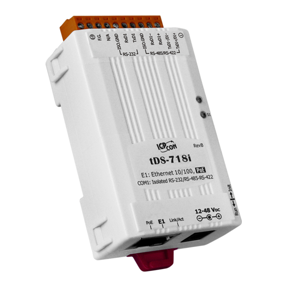
Page 15: Appearance
Tiny Serial-to-Ethernet Device Server 2.3 Appearance 5. Serial COM Ports 4. LED indicator 6. DIN-Rail Mounting 3. Operating Mode Switch 1. PoE and Ethernet RJ-45 Jack 2. +12 to +48 V Jack ETH1 supports PoE, Ethernet 2. +12 to +48 V terminal ETH2 supports Ethernet only 1. -
Page 16: Poe And Ethernet Rj-45 Jack
Tiny Serial-to-Ethernet Device Server PoE and Ethernet RJ-45 Jack The tDS-700 series module is equipped with an RJ-45 jack that is used as the 10/100 Base-TX Ethernet port and features networking capabilities, supports PoE power supply. The DS-2200 series module is equipped with two RJ-45 jacks that are used as the 10/100 Base-TX Ethernet port and features networking capabilities, only ETH1 supports PoE power supply. -
Page 17: Led Indicator
Serial Port Busy Rapid flashing – Once every 0.2 seconds The following serial port LED indicators are tDS-718i-D only. You can change the serial interface via web server. An overview of the serial Port LED functions is given below: Function... -
Page 18: Din-Rail Mounting
Tiny Serial-to-Ethernet Device Server DIN-Rail Mounting The tDS-700/DS-2200 series modules include simple rail clips on the bottom of the chassis that allow them to be reliably mounted on a DIN-Rail or a wall. For more detailed information regarding DIN-Rail Mounting, refer to the illustration in figure below. -
Page 19: Dimensions
Tiny Serial-to-Ethernet Device Server 2.4 Dimensions The following diagrams provide the dimensions of the tDS-700/DS-2200 series module and CA-002 cable that can be used as a reference when defining the specifications and the DC power supply plug for any custom enclosures. All dimensions are in millimeters. 2.4.1 tDS-700 Series Module ... - Page 20 Tiny Serial-to-Ethernet Device Server tDS-712i/718i-D: tDS-722(i)/732(i)/715(i)/725(i)/735(i)/718(i)/724(i)/734(i): Copyright © 2020 ICP DAS CO., Ltd. All Rights Reserved. -20 -...
-
Page 21: Ds-2200 Series Module
Tiny Serial-to-Ethernet Device Server 2.4.2 DS-2200 Series Module DS-2212i/2222i/2232i/2215i/2225i/2235i DS-2212i/2215i 1 port DS-2222i/2225i 2 ports DS-2232i/2235i 3 ports Copyright © 2020 ICP DAS CO., Ltd. All Rights Reserved. -21 -... -
Page 22: Cable
Tiny Serial-to-Ethernet Device Server 2.4.3 CA-002 Cable Note: Cable color: BLACK DESCRIPTION UNIT UL2464 18AWG 2C(RED/BLACK) 0D5.0 COLOR BLACK OPEN DC PLUG 5.5*2.1 BLACK OPEN PVC:45/P BLACK Copyright © 2020 ICP DAS CO., Ltd. All Rights Reserved. -22 -... -
Page 23: Pin Assignments
Tiny Serial-to-Ethernet Device Server 2.5 Pin Assignments tDS-712/tDS-712i/tDSM-712 tDS-712/tDSM-712 tDS-712i Terminal No. Pin Assignment COM1 CTS1 CTS1 RTS1 RTS1 ISO.GND TxD1 TxD1 RxD1 RxD1 tDS-722/tDS-722i tDS-722 tDS-722i Terminal No. Pin Assignment F.G. F.G. CTS2 CTS2 RTS2 RTS2 COM2 RxD2 RxD2 TxD2 TxD2 ISO.GND... -
Page 24: Tds-732/Tds-732I
Tiny Serial-to-Ethernet Device Server tDS-732/tDS-732i tDS-732 tDS-732i Terminal No. Pin Assignment F.G. F.G. ISO.GND COM3 RxD3 RxD3 TxD3 TxD3 ISO.GND COM2 RxD2 RxD2 TxD2 TxD2 ISO.GND COM1 RxD1 RxD1 TxD1 TxD1 tDS-715/tDS-715i tDS-715 tDS-715i Terminal No. Pin Assignment F.G. F.G. ISO.GND RxD1- RxD1-... -
Page 25: Tds-725/Tds-725I
Tiny Serial-to-Ethernet Device Server tDS-725/tDS-725i tDS-725 tDS-725i Terminal No. Pin Assignment F.G. F.G. ISO.GND COM2 ISO.GND COM1 tDS-735/tDS-735i tDS-735 tDS-735i Terminal No. Pin Assignment F.G. F.G. ISO.GND COM3 ISO.GND COM2 ISO.GND COM1 Copyright © 2020 ICP DAS CO., Ltd. All Rights Reserved. -25 -... -
Page 26: Tds-718/Tds-718I
RxD1 RxD1 TxD1 TxD1 ISO.GND RxD1- RxD1- RS-485/RS-422 RxD1+ RxD1+ TxD1-/D1- TxD1-/D1- TxD1/D1+ TxD1/D1+ tDS-718i-D RS-232 RS-422 RS-485 Terminal No. Pin Assignment COM1 RxD- RxD+ TxD+ Data+ TxD- Data- Copyright © 2020 ICP DAS CO., Ltd. All Rights Reserved. -26 -... -
Page 27: Tds-724/Tds-724I
Tiny Serial-to-Ethernet Device Server tDS-724/tDS-724i tDS-724 tDS-724i Terminal No. Pin Assignment F.G. F.G. ISO.GND CTS2 CTS2 RTS2 RTS2 COM2 ISO.GND RxD2 RxD2 TxD2 TxD2 ISO.GND COM1 tDS-734/tDS-734i tDS-734 tDS-734i Terminal No. Pin Assignment F.G. F.G. ISO.GND COM3 RxD3 RxD3 TxD3 TxD3 ISO.GND COM2... - Page 28 Tiny Serial-to-Ethernet Device Server DS-2212i/2222i/2232i DS-2212i DS-2222i DS-2232i Terminal No. Pin Assignment ISO.GND RTS3 COM3 CTS3 RxD3 TxD3 ISO.GND ISO.GND RTS2 RTS2 COM2 CTS2 CTS2 RxD2 RxD2 TxD2 TxD2 ISO.GND ISO.GND ISO.GND RTS1 RTS1 RTS1 COM1 CTS1 CTS1 CTS1 RxD1 RxD1 RxD1 TxD1...
- Page 29 Tiny Serial-to-Ethernet Device Server DS-2215i/2225i/2235i DS-2215i DS-2225i DS-2235i Terminal No. Pin Assignment ISO.GND RxD3- COM3 RxD3+ TxD3-/D3- TxD3+/D3+ ISO.GND ISO.GND RxD2- RxD2- COM2 RxD2+ RxD2+ TxD2-/D2- TxD2-/D2- TxD2+/D2+ TxD2+/D2+ ISO.GND ISO.GND ISO.GND RxD1- RxD1- RxD1- COM1 RxD1+ RxD1+ RxD1+ TxD1-/D1- TxD1-/D1- TxD1-/D1- TxD1+/D1+...
-
Page 30: Wiring Notes For Rs-232/485/422 Interfaces
Tiny Serial-to-Ethernet Device Server 2.6 Wiring Notes for RS-232/485/422 Interfaces RS-232 Wiring 3-wire RS-232 Connection 5-wire RS-232 Connection Note: FGND is the frame ground that is soldered to the metal shield on the DB-9 cable. Copyright © 2020 ICP DAS CO., Ltd. All Rights Reserved. -30 -... -
Page 31: Wiring
Tiny Serial-to-Ethernet Device Server RS-422 Wiring RS-485 Wiring Notes: 1. Usually, you have to connect all signal grounds of RS-422/485 devices together to reduce common-mode voltage between devices. 2. Twisted-pair cable must be used for the DATA+/- wires. 3. Both two ends of the cable may require a termination resistor connected across the two wires (DATA+ and DATA-). -
Page 32: Getting Started For Tds-700 Series
Tiny Serial-to-Ethernet Device Server 3. Getting Started for tDS-700 series This chapter provides detailed information about the “Self-Test” process, which is used to confirm that the tDS-700 series module is operating correctly. Before beginning the “Self-Test” process, the wiring test, Ethernet configuration and VxComm utility driver installation procedures must first be fully completed. - Page 33 Tiny Serial-to-Ethernet Device Server +12 to +48 V Jack Power Supply (Non-PoE) Host PC Uses Non-PoE Switch Power Supply (+12~+48V Ethernet Cable CA-002 Hub/Switch(NS-205) 4. Verify that the System (S1) LED indicatoris flashing. Red, OK 5. Perform a Self-test wiring check as follows: ...
- Page 34 Tiny Serial-to-Ethernet Device Server RS-422 Wiring: Connect the RxD1- to the TxD1- pins and connect the RxD1+ to the TxD1+ pins. RS-485 Wiring: While using RS-485 modules (e.g., tDS-715), you should wire the Data1+ with Data2+ signals, and wire the Data1- with Data2- signals for self-test.
-
Page 35: Comm Utility
Tiny Serial-to-Ethernet Device Server 3.2 Install the VxComm Utility The VxComm Utility can be obtained from the ICP DAS FTP site or the ICP DAS web site. The location of the download addresses are shown below: https://www.icpdas.com/en/download/index.php?nation=US&kind1=&model=&kw=VxComm 3.3 Configuring Network Settings 1. -
Page 36: Configuring The Virtual Com Ports
Tiny Serial-to-Ethernet Device Server 4. Enter the network settings information, including the IP, Mask and Gateway addresses, and then click “OK” button. The new settings for the tDS-700 will take effect within 2 seconds. If you don’t know the correct network configuration information, contact your Network Administrator to obtain the details. - Page 37 Tiny Serial-to-Ethernet Device Server 3. Click the “Add Server[s]” button. 4. Assign a COM Port number and click “OK” to save your settings. 5. Click on tDS-700 name and check the virtual COM port mappings on the PC. ...
-
Page 38: Configuring The Serial Port
Tiny Serial-to-Ethernet Device Server 6. Click the “Restart Driver” item in the “Tools” menu to display the “VxComm Utility: Restarting Driver” dialog box. 7. Click the “Restart Driver” button. 3.5 Configuring the Serial Port 1. Open a web browser, such as Google Chrome, Internet Explorer, or Firefox, and enter the URL for the tDS-700 module in the address bar of the browser, or click the “Web”... - Page 39 3. Click the “Port1” tab to display the Port1 Settings page. 4. Set interface mode for the “Interface” drop down options. (For the tDS-718i-D module only, Note: The interface settings depends on wiring method of other tDS-700 module please skit this step) your device.
-
Page 40: Testing Your Tds-700
Tiny Serial-to-Ethernet Device Server 3.6 Testing Your tDS-700 1. Back to VxComm Utility, Right click Port 1 and then choose the “Open COM Port” item. Right Click 2. Check that the configuration of the COM Port is correct and then click the “Open COM” button. ... - Page 41 Tiny Serial-to-Ethernet Device Server Note While using RS-485 modules (e.g., tDS-715), open the first two COM Ports and use one (e.g., COM2) to send data to and the other (e.g., COM3) to receive data. Copyright © 2020 ICP DAS CO., Ltd. All Rights Reserved. -41 -...
-
Page 42: Getting Started For Ds-2200 Series
Tiny Serial-to-Ethernet Device Server 4. Getting Started for DS-2200 series This chapter provides detailed information about the “Self-Test” process, which is used to confirm that the DS-2200 series module is operating correctly. Before beginning the “Self-Test” process, the wiring test, Ethernet configuration and VxComm Utility driver installation procedures must first be fully completed. - Page 43 Tiny Serial-to-Ethernet Device Server +12 to +48 V Jack Power Supply (Non-PoE) Host PC Uses Non-PoE Switch Power Supply (+12~+48V Ethernet Cable Hub/Switch(NS-205) 4. Verify that the System LED indicatoris flashing. Red, OK 5. Perform a Self-test wiring check as follows: ...
- Page 44 Tiny Serial-to-Ethernet Device Server RS-422 Wiring: Connect the RxD1- to the TxD1- pins and connect the RxD1+ to the TxD1+ pins. RS-485 Wiring: While using RS-485 modules (e.g., DS-2215i), you should wire the Data1+ with Data2+ signals, and wire the Data1- with Data2- signals for self-test.
-
Page 45: Comm Utility
Tiny Serial-to-Ethernet Device Server 4.2 Install the VxComm Utility The VxComm Utility can be obtained from the ICP DAS web site. The location of the download addresses are shown below: https://www.icpdas.com/en/download/index.php?nation=US&kind1=&model=&kw=VxComm 4.3 Configuring Network Settings 1. Double-click the VxComm Utility shortcut on the desktop. 2. -
Page 46: Configuring The Virtual Com Ports
Tiny Serial-to-Ethernet Device Server 4. Enter the network settings information, including the IP, Mask and Gateway addresses, and then click “OK” button. The new settings for the DS-2200 will take effect within 2 seconds. If you don’t know the correct network configuration information, contact your Network Administrator to obtain the details. - Page 47 Tiny Serial-to-Ethernet Device Server 3. Click the “Add Server[s]” button. 4. Assign a COM Port number and click “OK” to save your settings. 5. Click on DS-2200 name and check the virtual COM port mappings on the PC. ...
-
Page 48: Configuring The Serial Port
Tiny Serial-to-Ethernet Device Server 6. Click the “Restart Driver” item in the “Tools” menu to display the “VxComm Utility: Restarting Driver” dialog box. 7. Click the “Restart Driver” button. 4.5 Configuring the Serial Port 1. Open a web browser, such as Google Chrome, Internet Explorer, or Firefox, and enter the URL for the DS-2200 module in the address bar of the browser, or click the “Web”... - Page 49 Tiny Serial-to-Ethernet Device Server 3. Click the “Port1” tab to display the Port1 Settings page. 4. Select the appropriate Baud Rate and Data Format (e.g., 115200 and 8N1) from the relevant Note: The Baud Rate and Data Format settings depends on your device. drop down options.
-
Page 50: Testing Your Ds-2200
Tiny Serial-to-Ethernet Device Server 4.6 Testing Your DS-2200 1. Back to VxComm Utility, Right click Port 1 and then choose the “Open COM Port” item. Right Click 2. Check that the configuration of the COM Port is correct and then click the “Open COM” button. ... - Page 51 Tiny Serial-to-Ethernet Device Server Note While using RS-485 modules (e.g., DS-2215i), open the first two COM Ports and use one (e.g., COM2) to send data to and the other (e.g., COM3) to receive data. Copyright © 2020 ICP DAS CO., Ltd. All Rights Reserved. -51 -...
-
Page 52: Web Configuration
Tiny Serial-to-Ethernet Device Server 5. Web Configuration Once the tDS-700/DS-2200 module has been correctly configured and is functioning on the network normally, the configuration details can be retrieved or modified using either the VxComm Utility or a standard web browser. 5.1 Logging in to the tDS-700/DS-2200 Web Server The embedded tDS-700/DS-2200 series web server can be accessed from any computer that has an Internet connection. - Page 53 Tiny Serial-to-Ethernet Device Server Step 3: Enter the Password After the main login page is displayed, enter a password (the factory default password is “admin”), and then click the “Submit” button to continue. Use the Default Password: admin Step 4: Log in to the tDS-700/DS-2200 Web Server After logging into the tDS-700/DS-2200 web server, the main page will be displayed.
-
Page 54: Home Page
Tiny Serial-to-Ethernet Device Server 5.2 Home Page The Home link connects to the main page, which contains two parts. The first part of this page provides basic information about the tDS-700 hardware and software. The first part of this page provides basic information about the tDS-700/DS-2200 hardware and software. -
Page 55: Network Setting
Tiny Serial-to-Ethernet Device Server 5.3 Network Setting 5.3.1 IP Address Settings The Address Type, Static IP Address, Subnet Mask and Default Gateway values are the most important network settings and should always correspond to the LAN configuration. If they do not match, the tDS-700/DS-2200 module will not operate correctly. - Page 56 Tiny Serial-to-Ethernet Device Server The following is an overview of the parameters contained in the IP Address Settings section: Item Description IP Address Static IP: If no DHCP server is installed on the network, the network settings can be configured manually. Refer to Section “Manual Configuration”...
- Page 57 Tiny Serial-to-Ethernet Device Server Manual Configuration When using manual configuration, the network settings should be assigned in the following manner: Step 1: Select the “Static IP” option from the “Address Type” drop-down menu. Step 2: Enter the relevant details in the respective network settings fields. Step 3: Click the “Update Settings”...
-
Page 58: General Settings
Tiny Serial-to-Ethernet Device Server 5.3.2 General Settings The General Settings provides functions allowing items such as the Alias Name, System Timeout value, UART Watchdog value, Auto-logout value, Debug Message and CGI Configuration to be configured. The following is an overview of the parameters contained in the General Settings section: Item Description Default... - Page 59 Tiny Serial-to-Ethernet Device Server Item Description Default This parameter is used to configure the system timeout value. If there is no activity on the network for a specific period of time, the system will be rebooted based on the configured system System Idle timeout value.
-
Page 60: Restore Factory Defaults
Tiny Serial-to-Ethernet Device Server 5.3.3 Restore Factory Defaults Use the following procedure to reset all parameters to their original factory default settings: Step 1: Click the “Restore Defaults” button to reset the configuration. Step 2: Click the “OK” button in the message dialog box. Step 3: Check whether the module has been reset to the original factory default settings for use with the VxComm Utility. - Page 61 Tiny Serial-to-Ethernet Device Server The Forced Reboot function: can be used to force the tDS-700/DS-2200 to reboot or to remotely reboot the device. After the tDS-700/DS-2200 module has rebooted, the original login screen will be displayed requesting that you enter your Login Password before continuing. ...
-
Page 62: Remote Firmware Update
Tiny Serial-to-Ethernet Device Server 5.3.4 Remote Firmware Update Firmware update requires initialization and local network operations. Traditional firmware update requires adjusting the Init/Run Switch and reboots the module manually for the initialization of firmware update, while new firmware allows user to initialize the module via web interface without adjusting the hardware switch. -
Page 63: Serial Port Page
Tiny Serial-to-Ethernet Device Server 5.4 Serial Port Page The Port 1 Settings section provides functions allowing items such as port settings, serial data packing and pair-connection settings to be configured. 5.4.1 Port1 Settings A detailed description of the settings parameter is given the next page. Copyright ©... - Page 64 Loopback: the internal loopback is used to self-testing. This parameter is used to enable or disable pull-high/low resister Pull-High/Low Resister Disable for RS-485 or RS-422 of the tDS-718i-D only (1K Ohm). This parameter is used to enable or disable terminal resister Terminal Resister...
- Page 65 Tiny Serial-to-Ethernet Device Server Item Description Default Serial Data Packing Set the waiting time after last Tx of the request sent to the device. If the device does not respond within the timeout Slave Timeout (ms) 1000 value, the tDS-700/DS-2200 will return existing data via TCP package and process next request.
-
Page 66: Filter Page
Tiny Serial-to-Ethernet Device Server 5.5 Filter Page 5.5.1 Accessible IP (filter is disabled when all zero) The Accessible IP Settings section is used to query or edit the IP Filter List. The IP Filter List restricts the access of packets based on the IP header. If one or more IP address are saved to the IP Filter table, only clients whose IP is specified in the IP Filter List can access the tDS-700/DS-2200. -
Page 67: Monitor Page
Tiny Serial-to-Ethernet Device Server 5.6 Monitor Page After clicking the Monitor tab, the Current Connection Status page will be displayed showing detailed information regarding the current status of the serial port connection settings for the tDS-700/DS-2200 module. Copyright © 2020 ICP DAS CO., Ltd. All Rights Reserved. -67 -... -
Page 68: Change Password
Tiny Serial-to-Ethernet Device Server 5.7 Change Password After clicking the Password tab, the Change Password page will be displayed. To change a password, first enter the old password in the “Current password” field (use the default password “admin”) and then enter a new password in the “New password” field. Re-enter the new password in the “Confirm new password”... -
Page 69: Logout Page
Tiny Serial-to-Ethernet Device Server 5.8 Logout Page After clicking the Logout tab, you will be immediately logged out from the system and be returned to the login page. Copyright © 2020 ICP DAS CO., Ltd. All Rights Reserved. -69 -... -
Page 70: Typical Applications
Tiny Serial-to-Ethernet Device Server 6. Typical Applications This chapter provides some examples of typical scenarios for the tDS-700/DS-2200 module, including applications focused on the Virtual COM, Direct Socket Connection, Ethernet I/O, Pair- connection and TCP Client Mode, etc... Copyright © 2020 ICP DAS CO., Ltd. All Rights Reserved. -70 -... -
Page 71: Virtual Com Application
Tiny Serial-to-Ethernet Device Server 6.1 Virtual COM Application The tDS-700/DS-2200 series is designed to link RS-232/422/485 devices to an Ethernet network. The VxComm utility allows the built-in tDS-700/DS-2200 COM Port to be virtualized to a standard COM Port of a host PC, as shown below: In the configuration above, Meter-1 is virtualized to link to COM3 of the host PC. -
Page 72: Direct Socket Connection Applications
Tiny Serial-to-Ethernet Device Server 6.2 Direct Socket Connection Applications tDS-700/DS-2200 series module can accept the TCP connection (include raw data) directly, it also can communicate with TCP client and Serial Device in this way. For examples of socket connection test as follows: Copyright ©... - Page 73 Tiny Serial-to-Ethernet Device Server 1. Confirm that the tDS-700/DS-2200 modules are functioning correctly. Refer to Chapter 3 “Getting Started for tDS-700 series”, Chapter 4 “Getting Started for DS-2200 series” for more details. 2. Wire the slave device (e.g., M-7015, optional) with your tDS-700/DS-2200. For detailed RS-232/422/485 wiring information, refer to Section 2.6 “Wiring Notes for RS-232/485/422 Interfaces”.
- Page 74 Tiny Serial-to-Ethernet Device Server 7. Type the IP address of tDS-700/DS-2200 in the IP Address field and assign a TCP/IP port of tDS-700/DS-2200, and then click the “Open TCP” button. 8. Type a string (e.g., $02M) in the “Send” field and then click the “Send” button. If a response is received, it will be displayed in the received field.
-
Page 75: Ethernet I/O Applications
Tiny Serial-to-Ethernet Device Server 6.3 Ethernet I/O Applications Linking to I-7000 series modules The I-7000 series provides a variety of I/O operations, such as D/I, D/O, A/D, D/A, Counter and Frequency Measurement, etc. The I-7000 series was originally designed to be used with RS-485 networks, so the RS-485 of COM on the tDS-700/DS-2200 can be used to link to I-7000 series modules. - Page 76 Tiny Serial-to-Ethernet Device Server 2: Configure the system connection as shown below and click the “Start” button to begin logging data. 3: Open the log file in MS Excel to view the log data as shown in the example below: By using the I-7000 DCON utility and MS Excel in conjunction with VxComm technology, the signal data originating from I-7000 modules via the Ethernet network can be analyzed without the need to write custom programs.
-
Page 77: Pair-Connection Applications
Tiny Serial-to-Ethernet Device Server 6.4 Pair-connection Applications tDS-700/DS-2200 device servers can be used to create a pair-connection application (as well as serial-bridge or serial-tunnel), and then route data between two serial devices via TCP/IP, which is useful when connecting mainframe computers, servers or other serial devices that do not themselves have Ethernet capability. - Page 78 Tiny Serial-to-Ethernet Device Server The following are examples of pair-connection tests: Pair-connection Settings: Port Settings Pair-connection Settings (default) Model Remote TCP Baud Data Remote Application Port Rate Format Server IP Mode (default) IP Address of tDS-700 #2 tDS-700 #1 115200 Client 10001 tDS-700 #2...
- Page 79 Tiny Serial-to-Ethernet Device Server The image below shows an example of the setup for a pair-connection test: Figure 6-1 Step 2: Configuring the Ethernet Settings Contact your Network Administrator to obtain correct functioning network configuration tDS-700/DS-2200 modules (including the IP Address, Mask and Gateway details).
- Page 80 Tiny Serial-to-Ethernet Device Server Step 3: Configuring the Pair-connection (Client Mode) on the Web Server for tDS-700#1 1. Enter the URL address of the tDS-700#1 in the address bar of the browser. 2. Enter the password (default: admin) in the Login password field, and click the “Submit” button to enter the configuration page.
- Page 81 Tiny Serial-to-Ethernet Device Server 4. Select the appropriate Baud Rate and Data Format settings from the relevant drop down options, for example “115200”, “8”, “None” and 1”. 5. The pair-connection settings area as follows: 5-1: Select “Client” from the “Application Mode (Server Mode)” drop down options 5-2: Type the IP address of the tDS-700 #2 in the “Remote Server IP”...
- Page 82 Tiny Serial-to-Ethernet Device Server Step 4: Configuring the Pair-connection (Server Mode) on the Web Server for tDS-700#2 1. Enter the configuration page for the tDS-700 #2 web server. 2. Click the “Port1” link to enter the settings page of the tDS-700 #2. 3.
- Page 83 Tiny Serial-to-Ethernet Device Server 2. Double-click the Test2COM.exe program and type the relevant configuration as follows: 1. Double Click Test2COM.exe 7. Check Baud Rates: 115200 2. Type COM1\COM2 3. Check Data Bits: 8 4. Check Parity: None 8. Loop: 10 5.
-
Page 84: Tcp Client Mode Applications
Tiny Serial-to-Ethernet Device Server 6.5 TCP Client Mode Applications In TCP Client Mode, the tDS-700/DS-2200 can establish a TCP connection to a specific TCP slave device actively by TCP server program. The whole system should operate like this: The following are examples of TCP Client Mode tests: TCP Client Mode Settings: Port Settings Pair-connection Settings... - Page 85 Tiny Serial-to-Ethernet Device Server Follow the procedure described below: Step 1: Connecting to a network, a PC and a Power Supply 1. Confirm that the tDS-700/DS-2200 module is functioning correctly. Refer to Chapter 3 “Getting Started for tDS-700 series”, Chapter 4 “Getting Started for DS-2200 series” for more details.
- Page 86 Tiny Serial-to-Ethernet Device Server Step 2: Configuring the Ethernet Settings Contact your Network Administrator to obtain a correct and functioning network configuration (including the IP Address, Mask and Gateway details) for the tDS-700/DS-2200 module. Also refer to Chapter 3 “Getting Started for tDS-700 series”, Chapter 4 “Getting Started for DS- 2200 series”...
- Page 87 Tiny Serial-to-Ethernet Device Server 3. Click the “Port1” link to enter the settings page. 4. Select the appropriate Baud Rate and Data Format settings from the relevant drop down options, for example “115200”, “8”, “None” and 1”. 5. The pair-connection settings area as follows: 5-1: Select “Client”...
- Page 88 Tiny Serial-to-Ethernet Device Server Step 4: Testing the Pair-connection (TCP Client Mode) Functions 1. Install TcpIpEcho.exe (TCP/IP Test Server program) on your PC. The location of the download addresses are shown below: http://www.brothersoft.com/tcp-ip-test-server-27898.html 2. Run the TCPIPEcho.exe program. Figure 6-13 3.
- Page 89 Tiny Serial-to-Ethernet Device Server 7. This will be indicated an “Open” line in the TCP/IP Test Server dialog box. ⑦ Figure 6-15 8. Right click in the Port-List panel and then choose the “Open COM Port” item under the VxComm Utility.
- Page 90 Tiny Serial-to-Ethernet Device Server 10. Type a string (e.g., $01M) in the “send” field. 11. Click the “Send” button on the COM1 terminal (PC #1). 12. Confirm that TCP server (PC #2) will receive this string under the TCP/IP Test Server. 13.
-
Page 91: Cgi Configuration
Tiny Serial-to-Ethernet Device Server 7. CGI Configuration The tDS-700/DS-2200 series can be configured via convenient URL commands. This section lists the commands in URL format corresponding to the basic functions of tDS-700/DS-2200. Please make sure you have correctly configured the network settings for the tDS-700/DS-2200 before using CGI configuration. -
Page 92: Cgi Command List
Tiny Serial-to-Ethernet Device Server 7.2 CGI Command List Network Settings Function Name Parameter Name Value Constraint 0: Disable; Set Address Type dhcp 1: Enable; Set IP Address xxx.xxx.xxx.xxx Set Gateway gway xxx.xxx.xxx.xxx mask xxx.xxx.xxx.xxx Set Net Mask 1~65535 Set TCP Command Port cmdport assign.cgi Default: 10000... - Page 93 Tiny Serial-to-Ethernet Device Server Serial Port Settings Function Name Parameter Name Value Constraint (bits/S) Set Baud Rate baud0 & baud1 Data bits: 5 ~ 8; Set Data Format format0 & format1 Parity: n, e, o, m, s; Stop bits: 1, 2; 0: None;...
-
Page 94: Appendix A: Troubleshooting
Tiny Serial-to-Ethernet Device Server Appendix A: Troubleshooting A1. How do I restore the web password for the module to the factory default password? The instructions below outline the procedure for resetting the web password to the factory default Note: Be aware that ALL settings will be restored to the factory default values after the module is reset. value. - Page 95 Tiny Serial-to-Ethernet Device Server Step 3 Double-click the name of the module to open the Configure Server (UDP) dialog box, and modify the basic settings as necessary, e.g., the IP, Mask and Gateway addresses, and then click the "OK" button to save the new settings. Step 4 Reset the Init/Run switch on the tDS-700/DS-2200 module to the "Run"...
-
Page 96: Appendix B: Glossary
Tiny Serial-to-Ethernet Device Server Appendix B: Glossary 1. ARP (Address Resolution Protocol) The Address Resolution Protocol (ARP) is a telecommunication protocol that is used to convert an IP address to a physical address, such as an Ethernet address. Consider two machines A and B that share the same physical network. Each has an assigned IP address IP and IP , and a MAC address, MAC... -
Page 97: Ethernet
Tiny Serial-to-Ethernet Device Server 3. Ethernet The term Ethernet generally refers to a standard published in 1982 by Digital Equipment Corp., Intel Corp. and Xerox Corp. Ethernet is the most popular physical layer Local Area Network (LAN) technology in use today. 4. -
Page 98: Ip (Internet Protocol) Address
Tiny Serial-to-Ethernet Device Server 8. IP (Internet Protocol) Address Each interface on the Internet must have a unique IP address (also called an Internet address). These addresses are 32-bit numbers, and are normally written as four decimal numbers, one for each byte of the address for example “192.168.41.1”. -
Page 99: Socket
Tiny Serial-to-Ethernet Device Server Socket Each TCP segment contains a source and destination port number that can be used to identify the sending and receiving application. These two values, along with the source and destination IP addresses in the IP header, uniquely identify each connection. The combination of an IP address and a port number is called a socket. -
Page 100: Appendix C: Actual Baud Rate Measurement
Tiny Serial-to-Ethernet Device Server Appendix C: Actual Baud Rate Measurement Ideal Baud Rate (bps) Actual Baud Rate (bps) Error 0.00% 109.92 0.07% 298.48 0.51% 597.04 0.49% 1200 1197.6 0.20% 2400 2395.2 0.20% 4800 4790.4 0.20% 9600 9568.0 0.33% 14400 14392 0.05% 19200 19136... -
Page 101: Appendix D: Revision History
Added Chapter Appendix D: Revision History. Mar. 2018 Remove the package CD. Aug. 2018 Added the software and hardware information about the tDS-718i-D. Jun. 2020 Added the software and hardware information about the DS-2200 Series. Copyright © 2020 ICP DAS CO., Ltd. All Rights Reserved.
Need help?
Do you have a question about the tDS-718i-D and is the answer not in the manual?
Questions and answers