Table of Contents
Advertisement
Quick Links
Programmable Device Server
(For PDS(M)-700, PPDS(M)-700-MTCP, DS-700, PPDS-700-IP67)
User Manual
Programmable Device Server New Features
1. Virtual COM Technology
Your Powerful Tools
2. Virtual I/O Technology
3. Web-server Technology
Create New Ideas
4. MiniOS7 & Xserver Inside
5. Programmable Solution
Create New Applications
6. Industrial PoE Solution
7. Modbus/TCP to Modbus/RTU Gateway
Warranty
All products manufactured by ICP DAS are under warranty regarding defective materials for a
period of one year, starting from the date of delivery to the original purchaser.
Warning
ICP DAS assumes no liability for damages resulting from the use of this product. ICP DAS
reserves the right to change this manual at any time without notice. The information furnished
by ICP DAS is believed to be accurate and reliable. However, no responsibility is assumed by
ICP DAS for its use, nor for any infringements of patents or other rights of third parties
resulting from its use.
Copyright
Copyright 2008 by ICP DAS. All rights are reserved.
Trademark
The names used for identification only may be registered trademarks of their respective
companies.
PDS Series User Manual ( V1.4, Oct. 2009) ----- 1
Advertisement
Table of Contents

Related Manuals for ICP DAS USA PDS-700


Summary of Contents for ICP DAS USA PDS-700
- Page 1 Programmable Device Server (For PDS(M)-700, PPDS(M)-700-MTCP, DS-700, PPDS-700-IP67) User Manual Programmable Device Server New Features 1. Virtual COM Technology Your Powerful Tools 2. Virtual I/O Technology 3. Web-server Technology Create New Ideas 4. MiniOS7 & Xserver Inside 5. Programmable Solution Create New Applications 6.
-
Page 2: Table Of Contents
Table of Contents INTRODUCTION 1.1. THERNET OLUTIONS 1.2. ECHNOLOGY 1.3. ERVER ECHNOLOGY TYPICAL APPLICATIONS FOR THE PDS 2.1. RS-232/485/422 D EVICE ETWORKING 2.2. I/O A THERNET PPLICATIONS 2.3. I-7000 S INKING ERIES ODULES TO AN THERNET ETWORK 2.4. ONFIGURABLE THERNET OGGER HARDWARE INFORMATION 3.1. - Page 3 7.3. ROGRAMMING ON A CLIENT VIRTUAL I/O COMMANDS 8.1. $AA5 8.2. $AA6 8.3. $AAC 8.4. $AAC 8.5. $AAGCN 8.6. $AAL 8.7. $AAF 8.8. $AAM 8.9. 8.10. @AA(D 8.11. 8.12. #AA00 8.13. #AA1 8.14. 8.15. ~AA0 8.16. ~AA1 8.17. ~AA2 8.18. ~AA3 8.19.
- Page 4 TCP/IP TCP (T RANSMISSION ONTROL ROTOCOL UDP (U ATAGRAM ROTOCOL ATEWAY IP (I NTERNET ROTOCOL ADDRESS MAC (M EDIA CCESS ONTROL ADDRESS UBNET ARP (A DDRESS ESOLUTION ROTOCOL RARP (R EVERSE DDRESS ESOLUTION ROTOCOL ICMP (I NTERNET ONTROL ESSAGES ROTOCOL ACKET OCKET LIENTS AND...
- Page 5 If any of these items are missed or damaged, contact the local distributors for more information. Save the shipping materials and cartons in case you want to ship in the future. More Information: Documentations CD: Napdos\PDS\PDS-700\Document http://ftp.icpdas.com/pub/cd/8000cd/napdos/pds/pds-700/document/ VxComm Driver (Virtual COM) CD: \NAPDOS\ Driver\VxComm_Driver http://ftp.icpdas.com/pub/cd/8000cd/napdos/driver/vxcomm_driver/...
-
Page 6: Introduction
Ethernet network. The user-friendly VxComm Driver/Utility allows users to easily turn the built-in COM ports of the PDS-700 series into standard COM ports on a PC. By virtue of its protocol independence, a small-core OS and high flexibility, the PDS- 700 series is able to meet the demands of every network-enabled application. -
Page 7: Why Ethernets
1.1. Why Ethernet Solutions? Nowadays, the Ethernet protocol has become the de-facto standard for local area networks. Via the Internet, connectivity is occurring everywhere, from home appliances, to vending machines, to testing equipment, to UPS ...etc. An Ethernet network can link office automation and industrial control networks, access remote systems and share data and information between multivendor machines;... -
Page 8: Why V X Commt
1.2. Why VxComm Technology? In general, writing a TCP/IP program is more difficult than a COM port program, or the COM port communication system was built many years ago. As a result, a new technology, VxComm was developed to virtualize the COM ports of the PDS to allow up to 256 COM Ports to be used on the central computer. - Page 9 The VxComm driver controls all the details of the Ethernet TCP/IP programming technique; your COM port program will be able to access your serial devices through Ethernet in the same way as through COM port with the assistance of PDS and VxComm technology.
-
Page 10: Why Web Servert
1.3. Why Web Server Technology? Web server technology enables configuration of the PDS via a standard web browser interface, e.g. Internet Explorer, FireFox or Mozilla, etc. This means that it is easy to check the configuration of the PDS via an Ethernet network without needing to install any other software tools;... -
Page 11: Typical Applications For The Pds
2. Typical Applications for the PDS 2.1. RS-232/485/422 Device Networking --- Using Virtual COM Technology --- The PDS series is designed to link RS-232/485/422 devices to an Ethernet network. The VxComm utility allows the built-in PDS COM Port to be virtualized to a standard COM Port of the host PC as shown below: The original COM1/2 of the host PC... - Page 12 The I-7000 series provides a variety of I/O operations, such as D/I, D/O, A/D, D/A, Counter and Frequency Measurement, etc. The I-7000 series was originally designed to be used with RS-485 networks, so COM2 on the PDS-700 can be used to link to I-7000 series modules.
- Page 13 2.3. Linking I-7000 Series Modules to an Ethernet Network The I-7000 family was originally designed for use with an RS-485 network. They are very robust and work well under the harsh industrial environments. The PDS enables I-7000 modules to be upgraded to an Ethernet solution. Linking I- 7000 modules to an Ethernet combines the advantages of both RS-485 and Ethernet solutions and expands RS-485 applications to the whole world.
- Page 14 2: Configure the system connection as shown below and click the “Start” button to begin logging data. 3: Open the log file in Excel to read the log data as shown in the example below: PDS Series User Manual ( V1.4, Oct. 2009) ----- 14...
- Page 15 By using the I-7000 DCON utility and MS Excel in conjunction with the VxComm technology, the signal data of I-7000 modules from the Ethernet network can be analyzed without the need to write custom programs. For more information about the log function refer to the online help feature (English and Traditional Chinese) of the DCON utility.
-
Page 16: Hardware Information
3. Hardware information 3.1. Features Incorporate Serial Devices in an Ethernet network "Virtual COM" Extend COM Ports Virtual COM on Windows NT 4.0, 2000/XP/2003 and Vista32 Watchdog Timer suitable for use in harsh environments Power Reverse Polarity Protection Serial Port +/-4 kV ESD Protection Circuit Self-Tuner ASIC Controller on the RS-485 Port RoHS Compliant with no Halogen Built-in High Performance MiniOS7 from ICP DAS... -
Page 17: Specifications
3.2. Specifications System Specifications PDS(M)-700(D)/PPDS(M)-700(D)-MTCP 80186-80 MHz or compatible SRAM 512 KB Flash Memory Flash ROM: 512 KB; Erase unit is one sector (64 KB); 1000,000 erase/write cycles EEPROM 16 KB; Data retention: 40 years; 1,000,000 erase/write cycles Built-in Watchdog Timer Communication Interface Models PDS(M)-700(D) - Page 18 IO Specifications Models PDS(M)-700(D) PPDS(M)-700(D)-MTCP Digital Output Output Type Open Collector (Sink/NPN) Load Voltage 30 V , max. Load Current 100mA, max. Isolated Voltage Non-isolated Digital Input Input Type Source (Dry Type), Common Ground Off Voltage Level +1 V max. On Voltage Level +3.5 ~ +30 V Isolated Voltage...
- Page 19 DS-700/PPDS-712-MTCP/PPDS-715-MTCP 80186-80 MHz or compatible SRAM 512 KB Flash ROM: 512 KB; Erase unit is one sector (64 KB); 1000,000 erase/write Flash Memory cycles EEPROM 16 KB; Data retention: 40 years; 1,000,000 erase/write cycles Built-in Watchdog Timer Communication Interface Models DS-712 PPDS-712-MTCP Non-isolated...
- Page 20 PPDS-700-IP67 80186-80 MHz or compatible SRAM 512 KB Flash Memory Flash ROM: 512 KB; Erase unit is one sector (64 KB); 1000,000 erase/write cycles EEPROM 16 KB; Data retention: 40 years; 1,000,000 erase/write cycles Built-in Watchdog Timer Communication Interface COM1 RS-232 (TxD, RxD, RTS, CTS, GND) Non-isolated COM2 RS-485 (D2+, D2-, GND) Ethernet...
- Page 21 PDS-700/PPDS-700-MTCP Front View Removable Terminal Block for easy wiring DI/DO Channels Wiring Serial Ports information LED Indicator DIN-Rail for easy mounting Robust 7-Segment LED insulated and fire retardant case RJ-45 Jack for Wiring information 10/100M Ethernet and PoE (IEEE 802.3af, Class 1)
- Page 22 PDS-700/PPDS-700-MTCP Rear ViewP Robust, insulated and fire retardant case RoHS Compliance (for PCB/device) Frame Ground DIN-Rail Mounting CE Certification (for PCB/device) Initial Mode Switch Frame Ground DIN-Rail Lock PDS Series User Manual ( V1.4, Oct. 2009) ----- 22...
- Page 23 DS-700 Front View COM1: RS-232 Serial Ports LED Indicator DIN-Rail Robust for easy mounting insulated and fire retardant case RJ-45 Jack for 10/100M Ethernet Wiring information Wiring COM1: RS-422/485 information Serial Ports LED Indicator DIN-Rail Robust for easy mounting insulated and fire retardant case RJ-45 Jack for Wiring information...
- Page 24 PDSM-700/PPDSM-700-MTCP Front View Removable Terminal Block for easy wiring DI/DO Channels Wiring Serial Ports information Frame Ground LED Indicator 7-Segment LED Wiring information Robust insulated and fire retardant Metal case COM2: RS-485 RJ-45 Jack for 10/100M COM1: RS-232 Ethernet and PoE (IEEE 802.3af, Class 1) PDS Series User Manual ( V1.4, Oct.
-
Page 25: Pds Comparisont
PDS-782(D)- 5-wire 2-wire 3-wire 3-wire 3-wire 3-wire 3-wire 3-wire RS-232 RS-485 RS-232 RS-232 RS-232 RS-232 RS-232 RS-232 PDSM-700(D) = PDS-700(D) + Metal Casing I-7188EN is the similar product with PDS-700(D) PDS Series User Manual ( V1.4, Oct. 2009) ----- 25... - Page 26 PDS-700D = PDS-700 + 7-Seg. LED Display In the DI/DO column is the number of channels for each device. Some PDS-700 doesn’t have DIO function. DS-700 Series Non-Programmable Device Servers Model DI/DO COM1 COM2 COM3 COM4 COM5 COM6 COM7 COM8...
- Page 27 PPDS(M)-700(D)-MTCP Series Programmable Device Servers Model DI/DO COM1 COM2 COM3 COM4 COM5 COM6 COM7 COM8 Metal 5-wire PPDS-712-MTCP RS-232 RS-422 PPDS-715-MTCP RS-485 5-wire 2-wire PPDS-720(D)-MTCP RS-232 RS-485 PPDS-721(D)-MTCP 5-wire 2-wire RS-232 RS-485 PPDSM-721(D)-MTCP PPDS-732(D)-MTCP 5-wire 2-wire 5-wire RS-232 RS-485 RS-232 PPDSM-732(D)-MTCP PPDS-734(D)-MTCP 5-wire...
- Page 28 PPDS-700(D)-MTCP = PDS-700(D) + PoE + Modbus PPDS-700D-MTCP = PPDS-700-MTCP + 7-Seg. LED Display In the DI/DO column is the number of channels for each device. Some PPDS-700-MTCP doesn’t have DIO function. PPDS-700-IP67 Series Programmable Device Servers Model Ethernet COM1...
-
Page 29: Pin Assignments
3.4. Pin Assignments Pin Assignments for PDS-720(D)/PPDS-720(D)-MTCP models Only D-version modules have a 5-digit 7-SEG LED. PDS Series User Manual ( V1.4, Oct. 2009) ----- 29... - Page 30 Name Description CTS1 CTS pin RTS1 COM1 RTS pin (RS-232) RXD1 RXD pin TXD1 TXD pin INIT* Initialization pin (for enabling/disabling AUTOEXEC.BAT) Data+ pin COM2 (RS-485) Data- pin V+ Pin for the power supply (+10 ~ +30 V unregulated) GND Pin for the power supply (COM1 GND) 10/100 Base-TX and PoE (IEEE 802.3af, Class 1) PDS Series User Manual ( V1.4, Oct.
- Page 31 PDS-721(D)/PPDS-721(D)-MTCP Pin Assignments Only D-version modules have a 5-digit 7-SEG LED. PDS Series User Manual ( V1.4, Oct. 2009) ----- 31...
- Page 32 PDSM-721(D)/PPDSM-721(D)-MTCP Pin Assignments Only D-version modules have a 5-digit 7-SEG LED PDS Series User Manual ( V1.4, Oct. 2009) ----- 32...
- Page 33 Name Description CTS1 CTS pin RTS1 RTS pin COM1 (RS-232) RXD1 RXD pin TXD1 TXD pin INIT* Initialization pin (for enabling/disabling AUTOEXEC.BAT) Data+ pin COM2 (RS-485) Data- pin V+ Pin for the power supply (+10 ~ +30 V unregulated) GND Pin for the power supply (COM1 GND) Digital Output channel 6 Digital Output channel 5 Digital Output channel 4...
- Page 34 PDS-732(D)/PPDS-732(D)-MTCP Pin Assignments Only D-version modules have a 5-digit 7-SEG LED. PDS Series User Manual ( V1.4, Oct. 2009) ----- 34...
- Page 35 PDSM-732(D)/PPDSM-732(D)-MTCP Pin Assignment Only D-version modules have a 5-digit 7-SEG LED PDS Series User Manual ( V1.4, Oct. 2009) ----- 35...
- Page 36 Name Description CTS1 CTS pin RTS1 RTS pin COM1 (RS-232) RXD1 RXD pin TXD1 TXD pin INIT* Initialization pin (for enabling/disabling AUTOEXEC.BAT) Data+ pin COM2 (RS-485) Data- pin V+ pin for the power supply (+10 ~ +30 V unregulated) GND pin for the power supply (COM1 GND) CTS3 CTS pin RTS3...
- Page 37 PDS-734(D)/PPDS-734(D)-MTCP Pin Assignments Only D-version modules have a 5-digit 7-SEG LED. PDS Series User Manual ( V1.4, Oct. 2009) ----- 37...
- Page 38 PDSM-734(D)/PPDSM-734(D)-MTCP Pin Assignments Only D-version modules have a 5-digit 7-SEG LED PDS Series User Manual ( V1.4, Oct. 2009) ----- 38...
- Page 39 Name Description CTS1 CTS pin RTS1 COM1 RTS pin (RS-232) RXD1 RXD pin TXD1 TXD pin INIT* Initialization pin (for enabling/disabling AUTOEXEC.BAT) COM2 Data+ pin (RS-485) Data- pin V+ pin for the power supply (+10 ~ +30 V unregulated) GND pin for the power supply (COM1 GND) COM3 TXD3+ TXD+ pin...
- Page 40 PDS-742(D)/PPDS-742(D)-MTCP Pin Assignments Only D-version modules have a 5-digit 7-SEG LED. PDS Series User Manual ( V1.4, Oct. 2009) ----- 40...
- Page 41 PDSM-742(D)/PPDSM-742(D)-MTCP Pin Assignments Only D-version modules have a 5-digit 7-SEG LED PDS Series User Manual ( V1.4, Oct. 2009) ----- 41...
- Page 42 Name Description CTS1 CTS pin RTS1 COM1 RTS pin (RS-232) RXD1 RXD pin TXD1 TXD pin Initialization pin (for enabling/disabling INIT* AUTOEXEC.BAT) COM2 Data+ pin (RS-485) Data- pin V+ pin for the power supply (+10 ~ +30 V unregulated) GND pin for the power supply (COM1 GND) CTS3 CTS pin RTS3...
- Page 43 PDS-743(D)/PPDS-743(D)-MTCP Pin Assignments Only D-version modules have a 5-digit 7-SEG LED. PDS Series User Manual ( V1.4, Oct. 2009) ----- 43...
- Page 44 PDSM-743(D)/PPDSM-743(D)-MTCP Pin Assignments Only D-version modules have a 5-digit 7-SEG LED PDS Series User Manual ( V1.4, Oct. 2009) ----- 44...
- Page 45 Name Description CTS1 CTS pin RTS1 COM1 RTS pin (RS-232) RXD1 RXD pin TXD1 TXD pin INIT* Initialization pin (for enabling/disabling AUTOEXEC.BAT) COM2 Data+ pin (RS-485) Data- pin V+ pin for the power supply (+10 ~ +30 V unregulated) GND pin for the power supply (COM1 GND) RXD4 COM4 RXD pin...
- Page 46 PDS-752(D)/PPDS-752(D)-MTCP Pin Assignments Only D-version modules have a 5-digit 7-SEG LED. PDS Series User Manual ( V1.4, Oct. 2009) ----- 46...
- Page 47 PDSM-752(D)/PPDSM-752(D)-MTCP Pin Assignment Only D-version modules have a 5-digit 7-SEG LED PDS Series User Manual ( V1.4, Oct. 2009) ----- 47...
- Page 48 Name Description CTS1 CTS pin RTS1 RTS pin COM1 (RS-232) RXD1 RXD pin TXD1 TXD pin INIT* Initialization pin (for enabling/disabling AUTOEXEC.BAT) Data+ pin COM2 (RS-485) Data- pin V+ pin for the power supply (+10 ~ +30 V unregulated) GND pin for the power supply (COM1 GND) CTS3 CTS pin RTS3...
- Page 49 PDS-755(D)/PPDS-755(D)-MTCP Pin Assignments Only D-version modules have a 5-digit 7-SEG LED. PDS Series User Manual ( V1.4, Oct. 2009) ----- 49...
- Page 50 PDSM-755(D)/PPDSM-755(D)-MTCP Pin Assignments Only D-version modules have a 5-digit 7-SEG LED PDS Series User Manual ( V1.4, Oct. 2009) ----- 50...
- Page 51 Name Description CTS1 CTS pin RTS1 COM1 RTS pin RXD pin (RS-232) RXD1 TXD1 TXD pin INIT* Initialization pin (for enabling/disabling AUTOEXEC.BAT) COM2 Data+ pin (RS-485) Data- pin V+ pin for the power supply (+10 ~ +30 V unregulated) GND pin for the power supply (COM1 GND) COM3 Data- pin (RS-485)
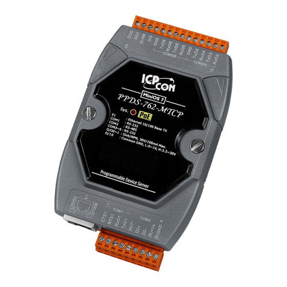
- Page 52 PDS-762(D)/PPDS-762(D)-MTCP Pin Assignments Only D-version modules have a 5-digit 7-SEG LED. PDS Series User Manual ( V1.4, Oct. 2009) ----- 52...
- Page 53 PDSM-762(D)/PPDSM-762(D)-MTCP Pin Assignments Only D-version modules have a 5-digit 7-SEG LED PDS Series User Manual ( V1.4, Oct. 2009) ----- 53...
- Page 54 Name Description CTS1 CTS pin RTS1 COM1 RTS pin (RS-232) RXD1 RXD pin TXD1 TXD pin INIT* Initialization pin (for enabling/disabling AUTOEXEC.BAT) COM2 Data+ pin (RS-485) Data- pin V+ pin for the power supply (+10 ~ +30 V unregulated) GND pin for the power supply (COM1 GND) RXD3 RXD pin TXD3...
- Page 55 PDS-782(D)/PPDS-782(D) Pin Assignments Only D-version modules have a 5-digit 7-SEG LED. PDS Series User Manual ( V1.4, Oct. 2009) ----- 55...
- Page 56 PDSM-782(D)/PPDSM-782(D) Pin Assignments PDS Series User Manual ( V1.4, Oct. 2009) ----- 56...
- Page 57 Name Description CTS1 CTS pin RTS1 COM1 RTS pin (RS-232) RXD1 RXD pin TXD1 TXD pin INIT* Initialization pin (for enabling/disabling AUTOEXEC.BAT) COM2 Data+ pin (RS-485) Data- pin V+ pin for the power supply (+10 ~ +30 V unregulated) GND pin for the power supply (COM1 GND) RXD3 COM3 RXD pin...
- Page 58 PDS-700-IP67 PDS Series User Manual ( V1.4, Oct. 2009) ----- 58...
- Page 59 PDS Series User Manual ( V1.4, Oct. 2009) ----- 59...
- Page 60 PDS Series User Manual ( V1.4, Oct. 2009) ----- 60...
- Page 61 DS-712/PPDS-712-MTCP Pin Assignments E1: 10/100 Base-TX PDS Series User Manual ( V1.4, Oct. 2009) ----- 61...
- Page 62 DS-715/PPDS-715-MTCP Pin Assignments E1: 10/100 Base-TX PDS Series User Manual ( V1.4, Oct. 2009) ----- 62...
-
Page 63: Pds Wiringc
3.5. PDS Wiring Connections COM1: The COM1 GND-signal is shared with pin9, GND Digital Input PDS Series User Manual ( V1.4, Oct. 2009) ----- 63... - Page 64 Digital Output PDS Series User Manual ( V1.4, Oct. 2009) ----- 64...
-
Page 65: Dimensions Andm
3.6. Dimensions and Mounting PDS-700/PPDS-700-MTCP Top View Bottom View Front View Din-Rail Mounting Bracket Side View Unit: mm Back View PDS Series User Manual ( V1.4, Oct. 2009) ----- 65... - Page 66 PDSM-700/PPDSM-700-MTCP PDS Series User Manual ( V1.4, Oct. 2009) ----- 66...
- Page 67 PPDS-700-IP67 PDS Series User Manual ( V1.4, Oct. 2009) ----- 67...
- Page 68 PDS Series User Manual ( V1.4, Oct. 2009) ----- 68...
- Page 69 Stack Mounting Din-Rail Mounting PDS Series User Manual ( V1.4, Oct. 2009) ----- 69...
-
Page 70: Pds Series Diagnostics
3.7. PDS series Diagnostics Indicator LED CTS1 RTS1 VxComm running: On/Off RXD1 TXD1 INIT* Xserver running: On/Off Step1: Apply power (+Vs, GND) to the PDS. PDS(M)-700 power supply can range from +10 V ~ +30 V. PPDS(M)-700-MTCP, DS-700, PPDS-700-IP67, PDS-782-25 power supply can range from +12 V ~ +48 V. - Page 71 Information related to the PDS series module can be classified into 4 main areas: Group ID 11111: The IP address information for the PDS-700 Group ID 22222: The Baud Rate for all COM Ports Group ID 33333: The COM Port configuration...
- Page 72 0), e.g. 12600 When LED-1 is 2, LED-2~5 indicates how many times the PDS has been reset, e.g. 20002 (The PDS-700 has been reset 2 times) When LED-1 is 3, the display indicates how many Ethernet packets are currently being received by the PDS.
- Page 73 If the 5-digit LEDs do not display the above detail, take the following steps: Power off the module Connect the INIT* pin to the VS+ pin Power on the module and double check the configuration Step 3: The red LED on the PDS is used to indicate the following: Unit 0.5 second The PDS contains either Xserver or VxComm as default when shipped that is in the...
-
Page 74: Setting Up The Pds Module
4. Setting up the PDS module Step 1: Connect the PDS module to the Ethernet Network Before connecting the PDS module to an Ethernet network, the following items are needed: 1. Power Supply:10 ~ 30 V (for PDS(M)-700) 12 ~ 48 V (for PPDS(M)-700-MTCP, DS-700, PPDS-700-IP67, PDS-782- (eg:DP-665:http://www.icpdas.com/products/Accessories/power_supply/power_list.htm 2. - Page 75 Connect the PDS series module and your computer to the same sub network or the same Ethernet Switch. Short the RXD1 and TXD1 pins of the PDS series module for execute a self-test. Supply 24 V (10 ~ 30 V ) power to the PDS(W)-700 module.
- Page 76 Step 2: Search for the PDS series module on the Ethernet network 1. Execute the VxComm Utility and then search for your PDS series module. 2. Double click the name of the PDS to open the configuration settings dialog box. Click the “Search Severs”...
- Page 77 IP/Mask/Gateway settings have been saved, then click the name of your PDS series module once to select it. Click the name of your PDS-700 module 2. Click the button, then assign a COM Port number and click “OK”...
- Page 78 3. Check the Virtual COM port numbers on the PC. Check the COM Port Click “Restart Driver” from the “Tools” menu, and then click the “Restart Driver” button to start the driver. Click the ”Restart Driver” button to start the driver PDS Series User Manual ( V1.4, Oct.
- Page 79 Step4: Testing your PDS 1. Connect the “RXD1” and the “TXD1” of the PDS series module, as shown in the diagram in Step1. 2. Right click Port 1 and then choose the “Open COM Port” option. 3. Check that the configuration of the COM Port is correct and then click the “Open COM”...
- Page 80 4. Type a string in the send field then click the send button. If a response is received, it will be displayed in the received field. Click “Send” to send a string to your PDS series module The response is displayed 5.
-
Page 81: Configuration With Web Browser
5. Configuration with Web Browser Once the PDS series module has been correctly configured and is networking normally, the configuration details can be retrieved or amended using either the VxComm Utility or a standard web browser, such as IE, FireFox, or Mozilla, etc. 5.1. -
Page 82: Network Settings
When the browser connects to the PDS, the first page that will be display is the Firmware Information page. 5.2. Network Settings PDS Series User Manual ( V1.4, Oct. 2009) ----- 82... - Page 83 Network (TCP/IP) Setup page IP Address Subnet Mask Gateway The above three items are the most important network settings and should always correspond to the LAN definition. If they do not match, the PDS series module will not operate correctly. If the settings are changed while the module is operating, any links to Virtual COM Port based applications currently in use will be lost and an error will occur.
- Page 84 Broadcast 1 = receive UDP broadcast packets 0 = reject UDP broadcast packets Connection WDT timeout (ms): default = 0 (disabled), min. = 10000. If the PDS series module does not receive any data from a client PC within the period of the “Connection WDT timeout”, the module will close the connection to the client.
-
Page 85: Ip Filter Setting
5.3. IP filter setting The IP filter setting limits which client PCs are able to link to the PDS series module via specific IP addresses. When one or more IP addresses are set in the filter table, only client PCs where the IP address is included in the range listed of the filter table will be able to connect to the PDS series module. -
Page 86: Com Port Settings
Click the “Update” button to validate the settings. 5.4. COM Port Settings The COM Port Settings list is saved in the EEPROM on the PDS series module. PDS Series User Manual ( V1.4, Oct. 2009) ----- 86... - Page 87 The Currently Used COM Port Settings list The COM Port Settings area Note: If the “Set COM Port” button is clicked without checking “Apply current setting”, option the new settings will be saved to the PDS only and the new settings will be valid after the next power-on.
- Page 88 Other settings: M0 mode M0: Transparent Mode (Multi-echo mode) Condition 1: One client sends a request to the PDS series module to access each device. The PDS series module echoes the data from each device to each connected client PDS Series User Manual ( V1.4, Oct. 2009) ----- 88...
- Page 89 Condition 2: No clients send any requests to the PDS series module. The PDS series module echoes data from the devices to each connected client. M1: Slave Mode (Single-echo mode) Condition 1: One client sends a request to the PDS series module to access the other devices.
- Page 90 Condition 2: No clients send any requests to the PDS series module. The PDS series module doesn’t echo any data from the devices to any client. In M1, the slave mode timeout setting is use to set the waiting time after last character of the request sent to the device.
- Page 91 PDS Series User Manual ( V1.4, Oct. 2009) ----- 91...
-
Page 92: Pair Connections
5.5. Pair Connection Setting? 1. Check your firmware version is later than v3.2.31[Jun 19 2009] PDS Series User Manual ( V1.4, Oct. 2009) ----- 92... - Page 93 2. Click “Set Remote VCOM3 connection” on the COM PORT setting page. 3. Select “Add COM” and type in the number of the local COM port to use. 4. And type in the number of the remote COM port, IP and cmd port. 5.
-
Page 94: Miscellaneous Settings
5.6. Miscellaneous settings Alias Name: allocates an alias to the PDS series module. Web Read Only: 0 = disabled, 1 = enabled If the “Web Read Only” properly is set to 1, enabled, the web server will not be able to save any new configurations to the PDS series module. To disable the “Web Read Only”... - Page 95 2. Set the new “Web Read Only” properly = 0 and click the “UPDATE” button. 3. Check that the current the “Web Read Only” = 0 and then click “Logout” to complete the operation. 4. User can restore PDS password to default value “admin” by using “config=RESET” console command (refer to section Console/Telnet Commands List).
-
Page 96: Modbus Testing & Protocol
6. Modbus Testing & Protocol Step 1: Install Modbus Utility on your PC The software is located at: CD: \ Napdos\Modbus\Modbus_Utility http://ftp.icpdas.com/pub/cd/8000cd/napdos/modbus/modbus_utility/ Step 2: Connecting the Modbus device to PPDS(M)-700(D)-MTCP 1. Keep up network connection status for your PPDS-700-MTCP. 2. Connect the Modbus device (Ex: M-7015) to PPDS-700-MTCP on COM2 (RS- 485 bus). -
Page 97: Modbus /Tcp Tom
6.1. Modbus/TCP to Modbus/RTU Gateway PPDS(M)-700(D)-MTCP series can work as a Modbus/TCP to Modbus/RTU gateway that support most SCADA/HMI communications based on the Modbus/TCP protocol. Step 1: Configuring COM Ports for Modbus Gateway Enter the IP address of the PPDS series module in the Address field and press “Enter” to connect to the PPDS series module. - Page 98 3. Check the COM Port for Modbus gateway setting. Step 2: Test Modbus/TCP to Modbus/RTU Gateway 1. Run the Modbus Utility program and then click the Modbus/TCP button. 2. Click on Client tools Modbus/TCP Client . PDS Series User Manual ( V1.4, Oct. 2009) ----- 98...
- Page 99 3. Enter the PPDS-700-MTCP IP address and then click the “Connect” button to connect the PPDS-700-MTCP. 4. Refer to “Protocol Description” and type the command in the command field then click the “Send Command” button. If the response data is correct, it means the test is success. - 99 -...
- Page 100 6.2. Testing Modbus device through Virtual COM Ports If want to use Modbus/RTU through Virtual COM Ports, you can refer to below steps. Step 1: Configuring COM Ports for Virtual COM 1. Enter the IP address of the PPDS series module in the Address field and press “Enter” to connect to the PPDS series module.
- Page 101 3. Add Server(s) in the VxComm Utility 4. Run Modbus Utility program and then click the Modbus/TCP button. 5. Click on “Client tools Modbus/RTU Client”. - 101 -...
- Page 102 6. Select your virtual COM port and baud rate (Default: 9600) on PPDS-700-MTCP, and then click the “Open” button. 7. Refer to “Protocol Description” and type the command in the command field then click the “Send Command” button. If the response data is correct, it means the test is success. PDS Series User Manual ( V1.4, Oct.
-
Page 103: Virtual I/O
7. Virtual I/O PDS series modules provide digital I/O lines, including PDS(M)-721(D), PPDS(M)- 721(D)-MTCP, PDS(M)-732(D), PPDS(M)-732(D)-MTCP, PDS(M)-734(D), PPDS(M)- 734(D)-MTCP, PDS(M)-743(D), PPDS(M)-743(D)-MTCP, PDS(M)-762(D), PPDS(M)- 762(D)-MTCP. The DI is 0 ~ 30 V wide range Digital Input, while the DO is 30 V/100 mA (max.), current sink, open collector digital output. - Page 104 4. Install the DCON Utility v4.5.0 (or later). The DCON Utility is located at: CD:\Napdos\driver\dcon_utility\ http://ftp.icpdas.com/pub/cd/8000cd/napdos/driver/dcon_utility/setup/ 5. Run the DCON Utility, and click the “COM Port” option on the toolbar 6. Check the Virtual COM Port number shown in the Port I/O field in the VxComm Utility.(Refer to Chapter 4 for more details) PDS Series User Manual ( V1.4, Oct.
- Page 105 7. Select the Virtual COM Port number. Check 115200 as the Baud Rate, DCON as the protocol, checksum disabled, parity as none, and then click the “OK” button. If your PDS is not equipped with digital I/O lines, the DCON Utility will return an “Open COM error!”...
- Page 106 8. Click the button to start searching for the PDS series module 9. When the PDS series module is found and is displayed in the DCON Utility, click the button to stop the search Your PDS series module 10. Click on the name of your PDS sries module. Click here PDS Series User Manual ( V1.4, Oct.
- Page 107 11. Click the “Digital Output” icon to change the high/low status of the DO. Since all DI lines are connected to DO lines, the DI read value will be 0 when the DO sends a high state, where as the DI read value will be 7.2.
- Page 108 2. Type the Virtual I/O command in the command column and click the “Send” button to send the command. For example, the command $01M is used to read the module name. 3. Receive a response from the PDS-700 module that the command was sent successfully. PDS Series User Manual ( V1.4, Oct. 2009) ----- 108...
- Page 109 7.3. Programming on a PC client The General DCON Application Programming Interface kit is a set of DLL (lib) functions designed to run on Windows 98/2000/XP that allow access to remote I/O modules such as the PDS, I-7000, I-8000 and I-87k series. The General DCON API kit is located at: CD:\ napdos\ driver\ dcon_dll_new\ ftp://ftp.icpdas.com/pub/cd/8000cd/napdos/driver/dcon_dll_new/...
- Page 110 The response “COM n Opened!” will be shown on the title bar. 4. Set the total number of DI and DO channels on your PDS series module. For instance, the PDS-732 is equipped with 4 DI channels and 4 DO channels. 5.
- Page 111 The functions in the General DCON API kit can be used to access the I/O lines on the PDS series module: Categorization Dll and lib used Call condition Starting function: Uart.dll Called once when the program starts. Uart.lib Open_Com() I/O functions dcon_pc.dll Calls the I/O functions for requirements dcon_pc.lib...
- Page 112 Open_Com() Description: This function opens the specified COM Port. Syntax: Open_Com(unsigned char cPort, DWORD dwBaudrate, char cData, char cParity, char cStop); Return: no error. Others error codes. Parameters: cPort COM Port number (1 ~ 255) dwBaudrate Communication Baud Rate Data bit, (8 for PDS) cData cParity 0 = No parity...
- Page 113 Send_Receive_Cmd () Description: This function sends a DCON command string and receives the response. Syntax: Send_Receive_Cmd(unsigned char cPort, char szCmd[], char szResult[], WORD wTimeOut, WORD wChksum, WORD *wT) Return: no error Others error codes Parameters: cPort COM Port number (1 ~ 255) szCmd[] the send string, 1024 bytes maximum, without a zero (0x0D) character szResult[]...
- Page 114 DCON_Write_DO () Description: This function sends a group of digital output data to the PDS series module. Syntax: DCON_Write_DO(unsigned char cComPort, short iAddress, short iSlot, short iDO_TotalCh, unsigned long lDO_Value, short iCheckSum, short iTimeOut); Return: no error Others error codes Parameters: cComPort COM Port number, 1 ~ 255...
- Page 115 DCON_Write_DO_Bit () Description: This function sends one bit of digital output data to the PDS series module. Syntax: DCON_Write_DO_Bit(unsigned char cComPort, short iAddress, short iSlot, short iChannel, short iDO_TotalCh, short iBitValue, short iCheckSum, short iTimeOut); Return: no error. Others error codes. Parameters: cComPort COM Port number, 1 ~ 255...
- Page 116 DCON_Read_DIO () Description: This function reads the DO and DI lines status. Syntax: DCON_Read_DIO(unsigned char cComPort, short iAddress, short iSlot, short iDI_TotalCh, short iDO_TotalCh, short iCheckSum, short iTimeOut, unsigned long * lDI_Value, unsigned long * lDO_Value, char * cDI_BitValue, char * cDO_BitValue);...
-
Page 117: Virtual I/O Commands
8. Virtual I/O Commands Command Format: (Leading)(Address)(Command)[CHK](cr) Response Format: (Leading)(Address)(Data)[CHK](cr) 2-character, “01” for PDS virtual I/O (Address) 2-character checksum, no checksum for PDS virtual I/O [CHK] carriage return (0x0D) for ending character of command (cr) Checksum Calculation: 1. Calculate the ASCII sum of all characters in the command (or response) string except for the return character (cr). - Page 118 General Command Sets Command Response Description Section $AA5 !AAS Reads the Reset Status $AA6 !AA(Data) Reads the Digital I/O Status $AAC Clears the Latched Digital Input $AACn Clears the Digital Input Count $AAGCN >AA(Data) Retrieves the I/O Channel Count $AALs !(Data) Reads the Latched DI $AAF...
- Page 119 8.1. $AA5 Description: This function reads the reset status Syntax: $AA5[CHK](cr) A delimiter character The address of the module (01 only for PDS) A command for reading the status Response: Valid Command: !AAs[CHK](cr) Invalid Command: ?AA[CHK](cr) *There will be no response if there is a syntax error or a communication error. A delimiter for a valid command A delimiter for an invalid command AA The address of the module (01 only for PDS)
- Page 120 8.2. $AA6 Description: This function reads the status of the digital I/O channels Syntax: $AA6[CHK](cr) A delimiter character The address of the module (01 only for PDS) A command for reading the digital I/O status Response: Valid Command: !ddff00[CHK](cr) Invalid Command: ?AA[CHK](cr) *A Syntax error or a communication error will result in no response.
- Page 121 8.3. $AAC Description: This function clears the latched status of the digital Input Syntax: $AAC[CHK](cr) A delimiter character The address of the module (01 only for PDS) A command for clearing latched digital inputs Response: Valid Command: !AA[CHK](cr) Invalid Command: ?AA[CHK](cr) *Syntax error or a communication error will result in no response.
- Page 122 8.4. $AACn Description: This function clears the digital input counter Syntax: $AACn[CHK](cr) A delimiter character The address of the module (01 only for PDS) A command for clearing the digital input count The digital input channel number Response: Valid Command: !AA[CHK](cr) Invalid Command: ?AA[CHK](cr)
- Page 123 8.5. $AAGCN Description: This function reads the digital input/output channel count Syntax: $AAGCN[CHK](cr) A delimiter character The address of the module (01 only for PDS) A command for reading the digital input/output channel count Response: Valid Command: >DINxxDONxx[CHK](cr) Valid Command: >DONxx[CHK](cr) (DO only) Invalid Command: ?AA[CHK](cr)
- Page 124 8.6. $AALs Description: This function reads the latched digital Input Syntax: $AALs[CHK](cr) A delimiter character The address of the module (01 only for PDS) A command for reading the latched digital input data 1 = read latch-high data 0 = read latch-low data Response: Valid Command: !(Data)[CHK](cr) Invalid Command:...
- Page 125 8.7. $AAF Description: This function reads the firmware version details Syntax: $AAF[CHK](cr) A delimiter character The address of the module (01 only for PDS) A command for reading the firmware version details Response: Valid Command: !AA(Data)[CHK](cr) Invalid Command: ?AA[CHK](cr) *A Syntax error or a communication error will result in no response. A delimiter for a valid command A delimiter for an invalid command The address of the module (01 only for PDS)
- Page 126 8.8. $AAM Description: This function reads the module name Syntax: $AAM[CHK](cr) A delimiter character The address of the module (01 only for PDS) A command for reading the module name Response: Valid Command: !AA(Data)[CHK](cr) Invalid Command: ?AA[CHK](cr) *A syntax error or a communication error will result in no response. A delimiter for a valid command A delimiter for an invalid command The address of the module (01 only for PDS)
- Page 127 8.9. @AA Description: This function reads the status of the digital input/output Syntax: @AA[CHK](cr) A delimiter character The address of the module (01 only for PDS) Response: Valid Command: >(Data)[CHK](cr) Invalid Command: ?AA[CHK](cr) *A syntax error or a communication error will result in no response. >...
- Page 128 8.10. @AA(Data) Description: This function sets the digital output Syntax: @AA(Data)[CHK](cr) A delimiter character The address of the module (01 only for PDS) (Data) The output value (Data) is one character for output channels less than 4 For the PDS(M)-762(D) modules, this will be from 0 to 3 For the PDS(M)-732(D), 734(D), 743(D) modules, this will be from 0 to F (Data) is two characters for output channels less than 8 For the PDS(M)-721(D) modules, this will be from 00 to 7F...
- Page 129 8.11. #AAn Description: This function reads digital input counter from channel n Syntax: #AAn[CHK](cr) A delimiter character The address of the module (01 only for PDS) The digital channel number (from 0) Response: Valid Command: !AA(Data)[CHK](cr) Invalid Command: ?AA[CHK](cr) *A syntax error or a communication error will result in no response. A delimiter for a valid command A delimiter for an invalid command The address of the module (01 only for PDS)
- Page 130 8.12. #AA00dd Description: This function sets the multi-channel Output Syntax: #AA00dd[CHK](cr) A delimiter character The address of the module (01 only for PDS) A command used to set multi-channel output The output value Response: Valid Command: >[CHK](cr) Invalid Command: ?[CHK](cr) Ignored Command:  *A syntax error or a communication error will result in no response.
- Page 131 8.13. #AA1ndd Description: This function sets the output of a single channel Syntax: #AA1ndd[CHK](cr) A delimiter character The address of the module (01 only for PDS) The command used to set the output of a single channel. n is the digital output channel number. 00: sets the digital output channel to off 01: sets the digital output channel to on Response: Valid Command:...
- Page 132 8.14. ~** Description: This function is used to let other modules know that the Host is OK Syntax: ~**[CHK](cr) A delimiter character The command for all modules Response: No response Example: Command Response No response Related Commands: Sec.7.15 ~AA0, Sec.7.16 ~AA1, Sec.7.17 ~AA2, Sec7.18 ~AA3eff, Sec.7.19 ~AA4P, Sec.7.20 ~AA4S, Sec.7.21 ~AA5P, Sec.7.22 ~AA5S PDS Series User Manual ( V1.4, Oct.
- Page 133 8.15. ~AA0 Description: The function reads the status of the Host Watchdog Syntax: ~AA0[CHK](cr) A delimiter character The address of the module (01 only for PDS) The command used to read the status of the module Response: Valid Command: !AASS[CHK](cr) Invalid Command: ?AA[CHK](cr) *A syntax error or a communication error will result in no response.
- Page 134 8.16. ~AA1 Description: This function clears the status of the Host Watchdog Syntax: ~AA1[CHK](cr) A delimiter character The address of the module (01 only for PDS) The command used to reset the status of the module Response: Valid Command: !AA[CHK](cr) Invalid Command: ?AA[CHK](cr) *A syntax error or a communication error will result in no response.
- Page 135 8.17. ~AA2 Description: This function reads the Host Watchdog Timeout Value Syntax: ~AA2[CHK](cr) A delimiter character The address of the module (01 only for PDS) The command used to read the Host Watchdog Timeout Value Response: Valid Command: !AAeff[CHK](cr) Invalid Command: ?AA[CHK](cr) *A syntax error or a communication error will result in no response.
- Page 136 8.18. ~AA3eff Description: This function sets the Host Watchdog Timeout Value Syntax: ~AA3eff[CHK](cr) A delimiter character The address of the module (01 only for PDS) The command used to set the Host Watchdog Timeout Value 1 = Enabled, 0 = Disabled The timeout value, from 01 to FF, the unit is 0.1 second Response: Valid Command: !AA[CHK](cr)
- Page 137 No response If the ~** command is not sent within 10 seconds, the LED on the module will begin to flash. The LED indicates that the status of the Host Watchdog Timeout is set. ~010 !0104 Read the status of the module. Returns the status of the Host Watchdog Timeout Value is set.
- Page 138 8.19. ~AA4P Description: This function reads the Power-on Values for the DO Syntax: ~AA4P[CHK](cr) A delimiter character The address of the module (01 only for PDS) The command used to read the power-on value for the DO Response: Valid Command: !AA(Data)[CHK](cr) Invalid Command: ?AA[CHK](cr)
- Page 139 8.20. ~AA4S Description: This function reads the Safe Values for the DO Syntax: ~AA4S[CHK](cr) A delimiter character The address of the module (01 only for PDS) The command used to read safe values for the DO Response: Valid Command: !AA(Data)[CHK](cr) Invalid Command: ?AA[CHK](cr) *A Syntax error or a communication error will result in no response.
- Page 140 8.21. ~AA5P Description: This function sets the Power-on Value for the DO Syntax: ~AA5P[CHK](cr) A delimiter character The address of the module (01 only for PDS) The command used to set the power-on value for the DO Response: Valid Command: !AA[CHK](cr) Invalid Command: ?AA[CHK](cr)
- Page 141 8.22. ~AA5S Description: This function sets the Safe Value for the DO Syntax: ~AA5S[CHK](cr) A delimiter character The address of the module (01 only for PDS) The command used to set the safe value for the DO Response: Valid Command: !AA[CHK](cr) Invalid Command: ?AA[CHK](cr)
- Page 142 8.23. Application Notes Hot Watchdog Status The Power On Reset or Module Watchdog Reset will return all output settings to Power On Values. The Host Watchdog Timeout will return all output values to Safe Values. Additionally, the status of the Host Watchdog, which can be read using the ~AA0 command, will be recorded as 04, and output commands will be ignored until the status is cleared to 0 by using command ~AA1.
- Page 143 Reset Status The Reset Status is set when the module is powered on or if it is reset by the Module Watchdog. The status can be cleared by using the Reset Status ($AA5) command. This is useful for checking the operating status of the module. When the Reset Status is set it means that the module has been reset and the output can be changed to the Power On Value.
- Page 144 <3> Output command value: If the Host Watchdog Timeout status is clear, and the user issues a digital output command, to the module to change the output value, such as @AA (Data) or #AABBDD, the module will respond “success” (receive >). Latch Digital Input If, for example, the user connects a key switch to the digital input channel and wants to read the keystrokes, the key input is a digital input pulse, and the keystroke will be lost.
- Page 145 9. Console / Telnet Commands List 9.1. Operation Flowchart PDS Power OFF Short INIT* and GND Open INIT* Power ON Power ON Run Mode Init Mode *for Virtual COM applications *for MiniOS7 Commands *for Downloading Firmware Short INIT* and GND Run Firmware (vc6_3230/autoexec) Console Mode...
- Page 146 9.2. Regulate Init/Normal Mode PDS-700(D), PPDS-700(D)-MTCP DS-700, PDS-782(D)-25 PDS Series User Manual ( V1.4, Oct. 2009) ----- 146...
- Page 147 PDSM-700(D), PPDSM-700(D)-MTCP Run Mode: Open INIT* Init Mode: Short INIT* and GND - 147 -...
- Page 148 PPDS-700-IP67 Run Mode: Open INIT* Init Mode: Short INIT* and GND PDS Series User Manual ( V1.4, Oct. 2009) ----- 148...
- Page 149 9.3. Comparison Sheet (Init/Run/Console Modes) Init* and VCOM Telnet Console Mode Firmware GND pins Commands Commands Commands Stop Init Init Mode is used to upgrade firmware and accepts MiniOS7 commands (from PDS.COM1) only. Running Open Run Mode is used for Virtual COM applications, and accepts Virtual COM commands (TCP port 10000) and Telnet commands (TCP port 23).
- Page 150 9.4. Command List Command Description IPFILTER Retrieves/Sets the IP addresses that are allowed to access the PDS. Queries the network configuration. (IP/Mask/Gateway/MAC addresses). IPCONF Lists all the status of sockets (Listen/Not Used Yet) together with the type of SOCKET each socket (TCP Server: Port No./UDP/Unused). Queries or sets the configuration of the COM Ports (Baud Rate/Parity /Stop Bits) Queries or sets the Broadcast parameter, which determines whether or not the...
- Page 151 9.4.1. IPFILTER Description: This command is used to query or edit IP filter table. The IP filter table restricts the access of packets based on the IP header. If one or more IP addresses are saved into the IP filter table, only clients whose IP is specified in the IP filter table can access the PDS.
- Page 152 Example: PDS Series User Manual ( V1.4, Oct. 2009) ----- 152...
- Page 153 9.4.2. IPCONF Description: This command is used to display the network configuration information, such as IP/Mask/Gateway/MAC addresses and the status of DHCP/ACK_Delay/Free Memory/Socket status. Effect: Immediate Command Argument Description ipconf Queries the network configuration. Example: - 153 -...
- Page 154 9.4.3. SOCKET Description: This command lists the status of all sockets (Listen/Not Used Yet) together with the type of each socket (TCP Server: Port No./UDP/Unused) If stat = 1, the socket is used. If stat = 0, the socket is not yet used. Take Effect: Immediately Command Argument...
- Page 155 9.4.4. COM Description: This command queries or sets the configuration of the COM Ports (Baud Rate/Parity/Stop bits). Effect: Immediate Command Arguments Description Queries the configuration of all COM Ports. Queries configuration of COM Port “n”. If n = 0, the configuration of all COM Ports will be listed in the same way as using the command “com”...
- Page 156 9.4.5. Broadcast Description: This command is used to Enable/Disable listening broadcast packets on PDS. Effect: Immediate Command Arguments Description Broadcast Queries the Broadcast settings. Sets Broadcast = 1. Broadcast The system is able to receive broadcast packets. Sets Broadcast = 0. Broadcast The system will ignore broadcast packets.
- Page 157 9.4.6. SystemTimeout (ms) Description: This command queries or sets the system timeout value. If the SystemTimeout is greater than zero, and the PDS does not receive any packets from any client for longer than the SystemTimeout period, the PDS will reboot itself. Effect: Immediate Command Arguments...
- Page 158 9.4.7. SocketTimeout (ms) Description: This command is used to query or set the SocketTimeout parameter. If the SocketTimeout is greater than zero, and the PDS does not receive any data from a client PC for longer than the SocketTimeout period, the PDS will close the socket connection between itself and the client PC.
- Page 159 9.4.8. M Description: This command is used to query or set the echo mode. Effect: Immediate Command Arguments Description Queries the echo mode settings. Sets the multi-echo mode to enable. When set to multi-echo mode, the PDS echoes data from a device to all clients that are connected.
- Page 160 9.4.9. EchoCmdNo Description: This command is used to query or set the EchoCmdNo parameter. The EchoCmdNo parameter is used to set whether the PDS prefixes the Virtual COM command to the corresponding response. (Virtual COM commands are used to configure a PDS through TCP port 10000) Effect: Immediate Command...
- Page 161 9.4.10. EndChar Description: This command is used to query or set the EndChar parameter. PDS sends out the response string from serial port to TCP client immediately when it received a char on the response string that matching the EndChar. Set EndChar = 00 to disable the EndChar feature.
- Page 162 9.4.11. IP Description: This command is used to query or set the IP address. Effect: After the next reboot. Command Arguments Description Queries the IP address. = xxx.xxx.xxx.xxx Sets the IP address. Example: 9.4.12. MASK Description: This command is used to query or set the subnet Mask value Effect: After the next reboot.
- Page 163 9.4.13. GATEWAY Description: This command is used to query or set the outgoing Gateway address of the subnet. Effect: After the next reboot. Command Arguments Description Gateway Queries the Gateway address. Gateway = xxx.xxx.xxx.xxx Sets the Gateway address Example: 9.4.14. MAC Description: This command is used to query the MAC address.
- Page 164 9.4.15. NAME Description: This command is used to query the name of a PDS series module. Effect: Setting the name is not allowed. Command Arguments Description name Queries the name of a PDS series module. Example: 9.4.16. ALIAS Description: This command is used to query or set the alias of a PDS series module. The maximum character length of PDS alias name is 16 bytes.
- Page 165 9.4.17. DHCP Description: This command is used to set the DHCP client to either enabled or disabled. DHCP function will get a dynamic IP address setting for PDS automatically. Thus it's recommended to disable DHCP function and use a static IP address setting. This prevents you to configure virtual COM mappings again and again.
- Page 166 9.4.18. UDP Description: This command is used to configure the UDP Search function. UDP is used to set the action mode for when a PDS series module receives a UDP search command. Effect: Immediate Command Arguments Description Rejects UDP search commands. The PDS will not reply to the UDP search command, and can not be searched again.
- Page 167 9.4.19. VER Description: This command is used to query the version information for a PDS series module. Effect: Setting the version information is not allowed. Command Argument Description Queries the version information. Example: 9.4.20. SAVE Description: This command is used to set the PDS series module to backup or no-backup “autoexec.bat”...
- Page 168 9.4.21. LOAD Description: This command is used to loads file to the built-in flash disk on PDS series module. It should be used to update firmware only. Effect: Immediate Command Argument Description The command is coordinated with the MiniOS7 “load” load command and can be used to renew the “vcom3230.exe,”...
- Page 169 [21-2] Save=1 Load vc6_3230.exe ※ When save = 1, system will back up the "autoexec.bat" and "vcom.ini" files to memory first, clear all files in the flash disk, and then load the "autoexec.bat" and "vcom.ini" files from memory and run the “load” command to load the specified file(s). - 169 -...
- Page 170 9.4.22. CONFIG Description: This command is used to clear the settings in the EEPROM. Effect: Immediate Command Argument Description Clears the settings in the EEPROM. config = RESET After reboot, the firmware will use the new (default) settings on EEPROM. Note: ("RESET"...
- Page 171 9.4.23. RESET Description: This command is used to reboot the PDS series module. Effect: Immediate Command Argument Description reset Reboot the PDS series module. Example: 9.4.24. QUIT Description: This command is used to stop and quit the firmware of PDS series module. Effect: Immediate Command Argument...
- Page 172 Appendix A: Linking to a Development PC To Ethernet 10/100 M hub CTS1 CA0910 RTS1 RXD1 TXD1 INIT* Step 1: Connect the download-cable, CA0910, between the PDS series module and COM 1 (or COM 2) of the development PC as per above the diagram. Step 2: Connect the INIT* pin to the GND pin, as shown in the above diagram.
- Page 173 Step 8: Read the configuration of the PDS: Read configuration command mask gateway setcom port Note: The configuration of the PDS as follows can be changed: Settings configuration command ip [new ip] mask [new mask] gateway [new gateway] mac [new mac] setcom port [baud][data_bit][parity][stop_bit] “setcom”...
- Page 174 Step 11: Execute ping 192.168.255.1 –t using a run command as follows: Execute Ping 192.168.255.1 on the PC client. The ping results should be smooth and continuous Note: 192.168.255.1 is the default IP of the PDS series module. The IP address can be changed using the instructions in step 8.
- Page 175 AC power supply, to provide better ESD protection for the module. The PDS-700, PPDS-700-MTCP, DS-700 module is designed with two Frame Ground contact points, Frame-Ground-A and Frame-Ground-B, as shown in the figure below.
- Page 176 PDS Series User Manual ( V1.4, Oct. 2009) ----- 176...
- Page 177 Glossary 1. Ethernet The term Ethernet generally refers to a standard published in 1982 by Digital Equipment Corp., Intel Corp. and Xerox Corp. Ethernet is the most popular physical layer local area network (LAN) technology today. Ethernet is a best-effort delivery system that uses CSMA/CD technology.
- Page 178 7. IP (Internet Protocol) address Every interface on an Internet must have a unique IP address (also called an Internet address). These addresses are 32-bit numbers. They are normally written as four decimal numbers, one for each byte of the address such as “192.168.41.1”. This is called dotted-decimal notation.
- Page 179 11. RARP (Reverse Address Resolution Protocol) RARP provides a method of dynamically mapping 48-bit MAC address to the corresponding 32-bit IP address. 32-bit IP address RARP 48-bit MAC address 12. ICMP (Internet Control Messages Protocol) No system works correctly all the time. ICMP provides a method of communicating between the Internet Protocol software on one machine and the Internet Protocol software on another.
- Page 180 16. Clients and Servers The client-server paradigm uses the direction of initiation to categorize whether a program is a client or server. In general, an application program that initiates peer to peer communication is called a client. End users usually invoke client programs when they use network services.
- Page 181 1. How to access the remote PDS that placed behind an NAT or firewall? remote site must have a NAT (or a router supports NAT) server. NAT stands for Network Address Translator. By using (configuring) the NAT server, NAT can forword (bypass) all specified tcp port connection to specified PDS devices.
- Page 182 2. How to open a virtual COM port that larger than "COM 9" by calling CreateFile() Win32 API? If you want to open "COM 10", the correct way to call the CreateFile() is as follows: CreateFile( "\\\\. \\COM10", // address of name of the communications device fdwAccess, // access (read-write) mode // share mode...
- Page 183 Keep-Alive Time (ms) and Connection-Broken Time (ms) in the server options. For more details, refer to the "Adding a 7188E, 8000E, PDS-700, DS-700 server and configuring the VxComm Driver" section of the VxComm Driver/Utility User Manual.
- Page 184 5. Why doesn't the VxComm Driver (PC) receive data from the PDS series module? Make sure that the PDS series module is operating in mode 0 (/M0). PDS series module has the following two communication modes: Transparent Mode (Multi-echo, shared). In this mode, data is echoed from the COM Ports of the PDS series module to each client that is connected to the PDS series module.
- Page 185 6. Does the transmission speed become faster when the serial device working with Serial to Ethernet device servers? The speed depends on the applications. For transparent applications, it includes Ethernet latency in transmission and may get slower. But you can improve the communication speed by increasing the baud rate since you placing the device server more close to serial device and reduce the communication distance.
- Page 186 Xserver applications, it can become faster. User can write their own Xserver applications to acquire data automatically, and then compress and transmit this large amount data at one time. Your application can reach high performance by pre-acquire data before asking by client and then response immediately. Traditional time used RS-232/485/422 transmit time (C * n modules)
- Page 187 7. Why does the PDS series module fail on a (public) Internet connection? The default IP address of the PDS series module is 192.168.255.1, which can be only used on a private Internet connection. A private network packet will not be routed via a (public) Internet connection, which is the reason why the PDS series module failed on the Internet.
- Page 188 A private internet client may communicate with a public Internet server (PDS series modules) only if the NAT service for the client is available. Note: IANA Internet Assigned Numbers Authority Request for Comments Internet Service Providers Network Address Translator PDS Series User Manual ( V1.4, Oct. 2009) ----- 188...
- Page 189 8. Can I use the SetCommState ( ) API to changes the Baud Rate/data format settings of a virtual COM port? Yes. In a Win32 environment, the CreateFile( ) API should be called to open the COM Port(s) and then the SetCommState( ) API can be used to configure the settings. Third-party tools may provide an OpenCom( ) function for accessing a COM port.
- Page 190 PDS-762 32 - 10 = 22 26/6 = 4 26/2 = 13 PDS-762D PDS-782 32 - 12 = 20 23/9 = 2 23/2 = 11 PDS-782D PDS-782-25 32 - 13 = 20 23/9 = 2 23/2 = 11 PDS-782D-25 Notes: 1.
- Page 191 10. Can I search or connect to PDS when my PC’s IP address is not in the IP filter list of PDS? How can I solve it? A. No, you cannot search or connect to PDS when the PC’s IP address is not in the IP filter list of PDS.
Need help?
Do you have a question about the PDS-700 and is the answer not in the manual?
Questions and answers