Table of Contents
Advertisement
Quick Links
Advertisement
Table of Contents

Subscribe to Our Youtube Channel
Related Manuals for Printronix Auto ID T800 Series


Summary of Contents for Printronix Auto ID T800 Series
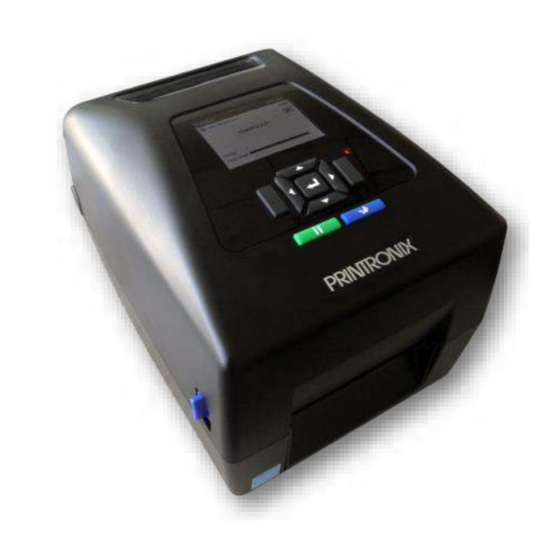
- Page 1 Administrator’ s Manual T800 Thermal Printers...
-
Page 2: Trademark Acknowledgements
Printronix Auto ID makes no representations or warranties of any kind regarding this material, including, but not limited to, implied warranties of merchantability and fitness for a particular purpose. Printronix Auto ID shall not be held responsible for errors contained herein or any omissions from this material or for any... -
Page 3: Regulatory Compliance
Regulatory Compliance EN 55032:2015 EN 55024 EN 60950-1 This is a class A product. In a domestic environment this product may cause radio interference in which case the user may be required to take adequate measures. FCC part 15B, Class A ICES-003, Class A This equipment has been tested and found to comply with the limits for a Class A digital device, pursuant to Part 15 of the FCC Rules. - Page 4 UL 60950-1 CAN/CSA-C22.2 No. 62368-1 NOM-019 CNS 13438 CNS 14336-1 CNS 15663 TP TC 004 TP TC 020 Important safety instructions: 1. Read all of these instructions and keep them for later use. 2. Follow all warnings and instructions on the product. 3.
- Page 5 5470-5725MHz exceeding 30mW Hereby, PRINTRONIX Auto ID Technology Co., Ltd. declares that the radio equipment type [Wi-Fi] IEEE 802.11 a/b/g/n/ac is in compliance with Directive 2014/53/EU The full text of the EU declaration of conformity is available at the following internet address: http://printronixautoid.com/declarations-of-conformity/...
- Page 6 前項合法通信,指依電信法規定作業之無線電通信。低功率射頻電機須忍受合法通信或工業、科學及醫療用 電波輻射性電機設備之干擾。(即低功率電波輻射性電機管理辦法第十四條) BSMI Class A 警語: 這是甲類的資訊產品,在居住的環境使用中時,可能會造成射頻 干擾,在這種情況下,使用者會被要求採 取某些適當的對策。 限用物質含有情況標示聲明 單元 Unit 限用物質及其化學符號 Restricted substances and its chemical symbols 六價鉻 多溴聯苯 多溴二苯醚 鎘 鉛Lead 汞Mercury Hexavalent Polybrominated Polybrominated Cadmium (Pb) (Hg) chromium biphenyls diphenyl ethers (Cd) (PBB) (PBDE) ○ ○ ○...
-
Page 7: Warnings And Special Information
Warnings and Special Information For your safety and to protect valuable equipment, read and comply with all information highlighted under special headings: WARNING Conditions that could harm you and damage the equipment. WARNING Achten Sie auf folgendes, um keine Personen in Gefahr zubringen bzw. das Gerät zu beschädigen. -
Page 8: Manual Conventions
Manual Conventions • Operator panel keys are printed in uppercase letters. Example: Press the PAUSE key and then press ENTER. • Operator panel keys are often shown by their symbol or icon (located on the control panel directly above the key). Example: Press the ... -
Page 9: Table Of Contents
Table of Contents Trademark Acknowledgements ................2 Regulatory Compliance ..................3 Warnings and Special Information ..............7 Important Safety Instructions ................7 Manual Conventions .................... 8 1 Introduction ..............17 The T800 Family of Printers ................17 Standard Features ..................... 17 Optional Features .................... - Page 10 Running Manual Calibrate ................40 Label Peel-Off (Optional) ................... 42 Loading Media Using Peel-Off Mode ............42 Configuring the Printer Menu ..............43 Media Cutter (Optional) ..................44 Loading Media Using Cutter Mode ............. 44 Configuring the Printer Menu ..............44 Printing Adjustments ..................
- Page 11 Media > Image .................... 60 Media > Speed .................... 66 Media > Handling ..................67 Media > Ribbon ................... 72 Media > TOF ....................72 Media > Fault ....................74 Media > Auto Label Map ................75 Auto Label Map Examples ................76 Example 1: Simple Case ................
- Page 12 Network > WLAN EAP ................127 Application ..................129 LP+, PGL, VGL Character Sets ..............129 Application > Control ................. 133 Application > PGL Setup ................138 Application > LP+ SETUP ................. 149 Application > P-SERIES Setup ..............154 Application > P-SERIES XQ Setup ............160 Application >...
- Page 13 PTX_SETUP Download................... 200 Manual Two-Key Download ................200 Downloading Files to the SD Card ..............201 Using TrueType Fonts ..................201 Downloading TrueType Fonts ..............201 PGL Emulation ..................201 Adding a Header/Manual Two-Key Download .......... 202 Header for SD Card ................... 203 Labeling Applications ................
- Page 14 Print Method ....................232 Media ......................233 Ribbon ....................... 235 Indicators and Switches ................235 Memory ..................... 236 Media Cutter Option .................. 236 Host Interfaces ..................237 Power ......................237 Environmental ................... 238 Physical ..................... 238 Acoustic Specifications ................238 B Printer Options ............
- Page 15 General Commands .................. 250 Summary of the CONFIG Command ............255 Operation of the FILE_IO Command ............255 Thermal Commands ................. 255 G Quick Change Memory Card (QCMC) ....... 258 Overview ......................258 Installing the QCMC ..................259 Saving the Printer’s Configuration to the QCMC ..........259 Copying the QCMC “Snapshot”...
- Page 16 Termination of License Agreement ............286 U.S. Government Restricted Rights ............286 Acknowledgement of Terms and Conditions ..........287 Warranty Information ..................288 PRINTER WARRANTY ................288 THERMAL PRINTHEAD ................288 SUPPLIES....................288 ON-SITE MAINTENANCE SERVICE ............288 Page | 16...
-
Page 17: Introduction
The terms “T800” and “printer” refer to both the T820 (203 DPI) and T830 (300 DPI) models. NOTE: The T800 series consists of a family of high quality, desktop direct thermal and thermal transfer printers specifically designed for printing labels and tags from multiple environments: •... -
Page 18: Optional Features
o ZGL interpreter for legacy ZPL (Zebra®) applications o TGL interpreter for legacy TEC (TEC®) applications o IGL interpreter for legacy IPL (Intermec®) applications o STGL interpreter for legacy SPL (SATO®) applications o DGL interpreter for legacy DPL™ (Datamax®) applications o IEGL interpreter for legacy IER-520®... -
Page 19: Operation
Operation Controls and Indicators Power Switch The power switch is located on the bottom back left panel of the printer. To apply power, place the switch in the | (ON) position. When you first power on the printer, an initialization sequence will immediately appear on the color LCD control panel. -
Page 20: Control Panel
Button Description Functionality When ONLINE, sets printer to OFFLINE Mode PAUSE Key Toggles the printer between and the UI to the Home Screen. ONLINE and OFFLINE Modes. When OFFLINE, puts the printer back ONLINE. Advances the media one label length. When FEED Key ONLINE, the menu System Control >... -
Page 21: Online Screen
Online Screen When the printer is ONLINE and ready to receive data, the ONLINE screen is shown. By default, this will be the first screen the user sees after the power-up process has completed. In order to demonstrate the full features of the ONLINE Screen, the following options are assumed: •... -
Page 22: Offline (Home) Screen
Item Description The WLAN active channel The WLAN SSID If there is a warning that needs to be displayed while ONLINE, a popup message will come onto the screen. For example, entering Power-Saver mode, Print Head Hot, etc. Offline (Home) Screen When the printer is taken OFFLINE using the PAUSE Key , the UI will show the Home screen. -
Page 23: Settings
→ When a Wizard has been completed (all steps executed until the end), the user is required to save their configurations per usual procedure (see Configuration). The exception to this is the first time the printer is powered up; in this case, the user is automatically taken into the Printer Setup Wizard and the configuration is automatically saved to Config 1 when completed. - Page 24 When an ICON is selected, the user moves into the View Level in which the screen is divided with the submenus on the left and the menu subsections on the right. As they traverse the submenus using the up/down arrow keys, the menu subsections on the right change so that users can quickly see the menu contents.
-
Page 25: Calibrate
Calibrate Calibration must be performed whenever new media or ribbon is installed or any configuration parameter that affects sensors is modified. Selecting this shortcut ICON and pressing the ENTER key will activate the Auto-Calibrate function, also available in Sensors > Calibrate > Auto Calibrate. Fault When faults occur, the user will be notified with the following screen on the display. -
Page 26: Media Handling Modes
When the printer is in OFFLINE mode and in the Home screen, the LEFT SOFT key will be labeled “Cancel Data” if there is Data in Buffer when the printer is taken OFFLINE. If there is no Data in Buffer, then the LEFT SOFT key label will not show anything. -
Page 28: Loading Ribbon
Loading Ribbon For direct thermal media (no ribbon required), go to “Loading Media” section. IMPORTANT Clean the printhead, platen roller, and media sensors every time you change the ribbon. See Cleaning the Printhead, Platen Roller, Media Sensors/Damper. 1. Open the printer top cover by pulling the blue levers, located on each side, toward the front of the printer, then lift the top cover. - Page 29 3. Install the paper core and ribbon to the hubs. For 0.5 or 1 inch paper roll with notches on both sides, please insert them at the hubs directly. Paper core for rewinding the used ribbon Ribbon Note: Please insert the right side of spindle first.
-
Page 30: Loading Media
5. Turn the blue ribbon rewind hub until the ribbon plastic leader is thoroughly wound and the black section of the ribbon covers the print head. Loading Media 1. Open the printer top cover by pulling the blue levers , located on each side, toward the front of the printer, then lift the top cover. - Page 31 2. Separate and hold open the blue media holders. 3. Place the roll between the holders and close them onto the core. 4. Separate the blue media guides. Black mark sensor RFID antenna Media guide slide (if equipped) Note: ▪ For black mark media or media with notch or holes used to indicate label length, the blue Black Mark sensor is moveable.
- Page 32 5. Place the paper, printing side face up, through the media sensor and place the label leading edge onto the platen roller. Move the blue media guides to fit the label width. 6. Press down on both sides of the top cover to close it gently. 7.
-
Page 33: Loading External Media
Loading External Media If using either an external media holder or folded labels, feed the media through the rear external label entrance chute. 1. Open the printer top cover by pulling the blue levers, located on each side, toward the front of the printer, then lift the top cover. -
Page 34: Positioning The Media Sensors
within the Settings section (Sensors > Calibrate > Auto Calibrate). Positioning the Media Sensors Your printer is equipped with two media sensors that detect the top-of-form position on media with label length indicators (gaps, notches, holes, or black marks). These sensors also detect when a Paper Out condition exists. - Page 35 Avoid Dark Pre-printing Extraneous Cut-out Vertical Gap and Rounded Die-cut Label Corners...
-
Page 36: Sensing Different Media Types
Sensing Different Media Types The printer’s media sensors can detect the different types of label length indicators on a large variety of media types. This is accomplished by selecting the correct sensor option: Gap, Mark, or Disable under Sensors > Control > Gap/Mark Sensor menu or within the “Printer Setup” Wizard. 1. - Page 37 Sensors > Control > Gap/Mark Sensor The available options specify the sensor type needed for detecting the Top-of- Form position on media with label length indicators (gaps, notches, holes, or black marks). Select when using media with no label length indicators (no gaps, notches, holes, or black marks), or Disable when you want the printer to ignore all existing label...
-
Page 38: Media With No Label Length Indicators
Calibrating the Media Sensors Due to manufacturing differences in media, the media sensors may have difficulty differentiating between the label and the liner or the label and the black mark. When this occurs, the printer may intermittently skip a label or display a fault message such as “GAP NOT DETECTED” or “PAPER OUT”. Media sensor sensitivity and reliability can be improved by changing the Sensors >... -
Page 39: Running Auto Calibrate
If Auto Calibrate continues to end with an incorrect Sensed Distance value displayed or a fault message displayed, refer to Running Manual Calibrate on page 40. NOTE: The amount of media sampled during Auto Calibrate is based on the length of a label and transitions detected, without error, between a label and its label length indicators. -
Page 40: Running Media Profile
values if no Auto or Manual Calibrate was performed. Figure 1 Media Profile Printout Gap Sensing This figure shows a Media Profile printout of a RFID label where the Gap/Mark Sensor is set to Gap in the Sensors > Control menu. In this example, the gap threshold value the printer selected (represented by the Gap/Mark dotted line) is too close to the value seen for the RFID antenna. -
Page 41: Running Manual Calibrate
To avoid this problem, increase the Threshold Range value to 60% or 70% in the Sensors > Calibrate> Threshold Range (the default is 50%), then perform a Running Auto Calibrate page 38. Any changes to Threshold Range will not take effect until you run an Auto Calibrate again. This will raise the Gap/Mark threshold high enough so that the printer will not falsely use the antenna as the gap (top-of-form). - Page 42 5. Select the “Diagnostics” submenu and press ENTER. 6. Find “Manual Calibrate” and then press ENTER to start the process. 7. Follow the instructions displayed on the LCD and press the ENTER key to move to the next step. 8.
-
Page 43: Label Peel-Off (Optional)
Label Peel-Off (Optional) You can set up the printer to automatically peel die-cut labels off their liner (backing) and dispense them one at a time while rewinding the liner. For installation information, refer to Appendix D. Loading Media Using Peel-Off Mode 1. -
Page 44: Configuring The Printer Menu
4. Close the peel-off front door. 5. Press down on both sides of the top cover to close. Configuring the Printer Menu 1. Press the PAUSE key to place the printer OFFLINE (Home Screen). 2. Set Media Handling to “Peel-Off” within the Application Wizard or directly in Media > Handling > Media Handling menu. -
Page 45: Media Cutter (Optional)
Media Cutter (Optional) You can set up the printer to automatically cut printed media when the media exits the printer. For installation information, refer to Appendix C. Loading Media Using Cutter Mode 1. Please follow "Loading Media" above to load the media and calibrate the sensors before the next step to avoid paper jams. -
Page 46: Printing Adjustments
Printing Adjustments Printhead Burn Line Adjustment The print head burn line adjustment are used to fine tune the print quality for different thicknesses of media. Adjust the print head’s burn line forward or backward as it relates to the platen roller. The print head burn line default is set for general purpose printing media (plain paper and paper thickness less than 0.20mm). -
Page 47: Cleaning
Cleaning Depending on the media used, the printer may accumulate residues (media dust, adhesives, etc.) as a by-product of normal printing. To maintain top printing quality, you should remove these residues by cleaning the printer periodically. WARNING Set the printer power switch to O (Off) prior to performing any cleaning tasks. Leave the power cord connected to keep the printer grounded and to reduce the risk of electrostatic damage. -
Page 48: Platen Roller Cleaning
WARNING If you have just been printing, allow one minute for the printhead to cool down to avoid burns from accidental printhead contact. • CAUTION Avoid electrostatic damage to the printhead by first making hand contact with an unpainted part of the printer frame or by using an anti-static wrist strap grounded to the printer frame. -
Page 49: Cutter Option Cleaning
NOTE: An Isopropyl Alcohol Wipe or Printhead Cleaning Pen can be used to remove label adhesive from the upper sensor. • Schedule - Clean the media sensors each time you clean the printhead. 1. Brush away or vacuum any dust or debris from the upper and lower sensor before using the cleaning pen or wipe. -
Page 50: Printer Settings
Printer Settings Overview This chapter provides information about: • Setting, saving, modifying, and printing configurations • Structure of the configuration • Menu and Configuration Parameters Setting Printer Configuration Parameters Configuration parameters are set from the control panel and stored into the printer’s flash memory. The parameters define how the printer will respond to command and interface signals from the host computer. - Page 51 When the desired submenu is highlighted, the user can press ENTER or the RIGHT ARROW key to move into the Edit Level. Likewise, the user can use the LEFT ARROW key to move back to the ICON Level. The Edit Level. The last level of the menu system is known as the Edit Level and contains all the configuration parameters for a given submenu.
-
Page 52: Saving A Configuration
When users are in Edit Mode, they can change to a new value by either pressing the ENTER key, or using the RIGHT SOFT key to “Apply”. Likewise, the users can exit Edit Mode without any modification to the menu by using the LEFT SOFT key to “Cancel” the operation. ... -
Page 53: Auto Save Configuration
Auto Save Configuration If you make any changes to the current configuration menu items and do not save them manually via the Configs > Control > Save Config menu, you will be prompted to save the changes just before you place the printer ONLINE with the screen shown below. -
Page 54: Loading A Configuration
When a configuration to name is selected, a virtual keyboard will be provided for the user to enter the name desired. The navigation keys can be used to find characters with the ENTER button used to select them. When the string is complete, the user should use the RIGHT SOFT key labelled “Apply”. Loading a Configuration You can specify any one of the nine configurations (1-8 or Factory) to load into DRAM using the Configs >... -
Page 55: Specifying A Power-Up Configuration
Specifying a Power-Up Configuration You can specify any one of the nine configurations (1-8 or Factory) as the power-up configuration using the Configs > Control > Power-Up Config menu. If the selected configuration has not been saved, the user will be warned with a “CONFIG DOES NOT EXIST”... -
Page 56: Settings Organization
Settings Organization This section will show how the configuration menus are organized under the icons in the Settings section. Screen #1 Quick Setup Sensors Media Media Control Image Sensors Calibrate Speed Application Diagnostics Handling Configs Ribbon Admin User Top of Form Faults Auto Label Map Host I/O... -
Page 57: Quick Setup
Quick Setup Quick Setup is a collection of the most typical setup parameters from different sections gathered in one place. It is designed to help the users quickly find these parameters and get the printer installed and running. There is also a feature called “Admin User” that administrators can use to restrict users to the Quick Setup functionality and not allow them to go into the other sections. -
Page 58: Entering Safe Mode
Quick Setup Menu Description / Location of Menu Configs Save Config Configs > Control > Save Config Power-Up Config Configs > Control > Power-Up Config Quick Setup Menu Description / Location of Menu Admin User Set Password Only available in Quick Setup when not in Safe Mode. Enter Safe Mode Only available in Quick Setup when not in Safe Mode. -
Page 59: Forgot The Password
There is no lockout if you enter the wrong password several times, so you can continue to try. If you cannot find or remember the password, then see section Forget the Password below. Forgot the Password If you forget the password to exit Safe Mode, then contact your Printronix Customer Support team for more help unlocking the printer. -
Page 60: Media
Media IMPORTANT All distances under Media can be represented in inches or millimeters based on the menu System > Control > Media Units. Intro: Label Length Understanding your media and application is very important when configuring the parameters in the menu system. -
Page 61: Media > Image
• An occasional blank label appears within a print job (in between printed labels). When Clip Page is “Disable”, the printer ignores any pre-printed dark marks or multiple gaps on a label that could mistakenly be detected as the next top-of-form position based on the specified Media > Image > Label Length value. - Page 62 Media > Image > Intensity Shift This menu can be used to shift Print Intensity settings higher or lower. This allows for higher print intensity settings for certain media while maintaining a compatible Print Intensity value set by the host job. It can also be used to make slight adjustments for compatibility with other emulations.
- Page 63 Media > Image > Label Length This option specifies the user-selected Label Length. In most applications, the user-selected Label Length will match the physical label length. Physical label length is the actual label length of the media installed: Die-cut Labels: Measurable length of the removable label (leading edge to trailing edge).
- Page 64 Media > Image > Set Label Length This feature selects whether the Sensed Distance value derived from an Auto or Manual Calibrate will be used to set the Label Length menu. If no calibration is performed, this menu has no effect. The Sensed Distance will not override or change the Manual Label Length value.
- Page 65 Media > Image > Horizontal Shift This option specifies the amount to shift an image horizontally left (-) or right (+) for precise positioning on the label. The actual width of the image is not affected by this parameter. The adjustment is made in .01 inch increments. Minimum -1.00 inches Maximum...
- Page 66 Media > Image > Print Direction This option is the compass for print orientation. Not all IGP Emulation languages have the same definition of Portrait, Landscape, etc. The illustration below shows how Portrait is defined for both Head First and Foot First.
-
Page 67: Media > Speed
Media > Image > Vertical DPI Adj Adjusts the vertical print resolution. This can be used to compress or expand all printed forms by small amounts. 195 (203 DPI) Minimum 290 (300 DPI) 210 (203 DPI) Maximum 310 (300 DPI) Factory Default Match Head DPI Media >... -
Page 68: Media > Handling
Media > Speed > Slew Speed Control Controls how slew speed is chosen. By default, it will match Print Speed. Automatic Always the same as the print speed. Allows you to set the slew speed independently from Manual Print Speed by unhiding the Media > Speed > Slew Speed menu. - Page 69 Media > Handling > Media Handling This option specifies how the printer will handle the media (labels or tag stock). Printer prints on the media and sends it out the front Tear-Off Strip until the print buffer is empty, then positions the last label over the tear bar for removal.
- Page 70 Media > Handling > Continuous Mode Allows selection of special media modes when Continuous Media Handling mode (Continuous Media) is selected. Labels are printed and sent out the front. The cross perforation following the last printed label is not aligned at the tear bar.
- Page 71 Media > Handling > Peel Present This feature allows you to select which part of a label gets presented to the peel bar. Media is moved to next TOF after image printing before presenting media to the peel-off position. This Next TOF option is for standard labels where the gap/mark length is less than the printhead to peel bar distance (about...
- Page 72 MEDIA > Handling > Cal in Peel Mode This option allows you to perform a calibration in Peel-Off Media Handling mode. Calibration in Peel-Off mode does not stop and wait for you to remove peeled labels. Therefore, be prepared to remove the labels as they are automatically peeled.
-
Page 73: Media > Ribbon
Media > Ribbon Media > Ribbon > Ribbon Low When enabled and the amount of ribbon remaining on the supply spindle is approximately 75 to 50 meters or less, a “Ribbon Low” warning will pop up on the ONLINE screen. Disable No Ribbon Low warning will appear. - Page 74 Media > TOF > Ticket Save Mode This option determines the action of the media for Continuous (Standard), Tear-Off Strip and Cut Media Handling Modes after the printer is first powered up or after the printhead has been opened and then closed. When enabled, this option eliminates wasting label(s) or ticket stock when the printer advances media to search for the next TOF position.
-
Page 75: Media > Fault
Media > TOF > TOF Adjust Mode This option enables use of the Media > TOF > TOF Adjust Dist. Disable The TOF Adjust Dist menu value will not be used. Enable The TOF Adjust Dist menu value will be used. Factory Default Disable Media >... -
Page 76: Media > Auto Label Map
Media > Fault > Error Recover This option determines how the printer handles data that was printing when an error occurred. The printer will not reprint the label that was printing Disable when the error condition occurred. The printer reprints the label that was printing when the Enable error condition occurred. -
Page 77: Auto Label Map Examples
Media > Auto Label Map > Auto Label Width The width of a single label to be printed or the maximum width of the media that will be used for the print file. The value is selectable from 0.1 inch through the maximum print width of the printer. -
Page 78: Example 2: Uneven Number Case
Example 2: Uneven Number Case Problem: A file has been constructed with three horizontally adjacent 2.0” labels. The user now desires to use this file with a printer that has a 4.0” physical width. Solution #1 with Menu Settings: • Set Media >... -
Page 79: Example 3: Past Maximum File Width
Printer Operation for Solution #2: The printer will print the first 2.0” label by itself, the second 2.0” label by itself, and finally, the last 2.0” label by itself. See figure below. Example 3: Past Maximum File Width Problem: A file has been constructed with three horizontally adjacent 4.0” labels. The user now desires to use this file with a printer that has an 8.0”... -
Page 80: Sensors
Sensors Intro: Sensor Types When making changes in this section, there are certain implications that need to be understood because some menus are intimately related. For example, when the menu Sensors > Control > Gap/Mark Sensor is changed, this has an effect on other menu defaults as shown in Table 2 below. Table 2. - Page 81 Sensors > Control > Auto Calibrate This executable menu is used to improve the sensitivity and reliability of the Media Sensors in detecting gaps, notches, holes, or black marks on the installed media, as well as a paper out condition. The operation is successful when the Sensed Distance displayed correctly matches that of the installed media.
-
Page 82: Sensors > Calibrate
Sensors > Control > Gap/Mark Thresh This menu item sets a value that, when exceeded by the output of the media sensor, is recognized by the printer as a gap (or black mark). Upon calibration, the value displayed is equal to the gap/mark threshold value set by the procedure. - Page 83 Sensors > Calibrate > Power-Up Action Calibration activities when the printer is powered up. Disable No activities at power up. Auto Calibrate is performed at power-up. Once the Auto Calibrate is complete, the printer will momentarily Auto-Cal display the Sensed Distance determined by the Auto Calibrate.
- Page 84 Sensors > Calibrate > Online Action Whenever the printer is brought ONLINE, it automatically performs an Auto Calibrate if enabled. This option should only be set before any data is sent to the printer. Disable No Auto Calibration is performed when going ONLINE. Once the Auto Calibrate is complete, the printer Auto-Cal momentarily displays the Sensed Distance and then...
- Page 85 Sensors > Calibrate > Gap Length Gap Length is the actual length (height) of a label gap measured in .01 inch increments. Minimum 0.05 inches Maximum 1.00 inches Factory 0.12 inches You must enter the correct Gap Length. If the Gap WARNING Length is too long, the image will shift down from the leading edge (TOF) of the label.
- Page 86 Sensors > Calibrate > Use Label Length Determines whether or not Media > Image > Label Length is used during Auto Calibrate. This resolves problems where the sensor(s) may mistake high noise levels or preprinted images within the label as the gap, notch, hole, or black mark that could result in a sensed distance value much shorter than the actual label length.
- Page 87 Sensors > Calibrate > Threshold Range This option allows the user to select the optimal threshold range for the label stock. The printer defaults to using a threshold range of 50% of the positive going pulse (see Sensors > Diagnostics > Media Profile) that represents each gap, notch or mark detected after doing an Auto or Manual Calibrate.
-
Page 88: Sensors > Diagnostics
Sensors > Diagnostics Sensors > Diagnostics > Media Profile This executable menu provides a graphical printout showing the relationship of the Paper Out Threshold and the Gap/Mark Threshold. The profile printout assists you in setting the thresholds for difficult media. This includes pre- printed labels, and labels with poor gap/media dynamic range. -
Page 89: System
System System > Control System > Control > Display Language This parameter chooses the language that will appear on the control panel: English, German, French, Italian, Spanish, Portuguese, Simplified Chinese, Traditional Chinese, Korean, and Russian. Factory Default English System > Control > LCD Brightness The brightness of the control panel backlight. - Page 90 System > Control > Media Units Determines if distances in the MEDIA section are displayed in inches or millimeters. In Inches Inches are used. In Millimeters Millimeters are used. Factory Default In Inches System > Control > Batch Counter Displays the number of pages remaining to be printed in a print job on the ONLINE screen message area.
- Page 91 System > Control > Cancel Operation This option determines if the LEFT SOFT key in the Home screen will be used for “Cancel Data”. If so, then the LEFT SOFT key will be active when there is data in buffer. No option will be available to the user to Cancel Data Disable from the front panel.
-
Page 92: System > Energy Star
System > Energy Star System > Energy Star > Pwr Saver Time The time interval you specify for this parameter sets the amount of idle time before the printer goes into Power Saver mode. When you enter into Power Saver mode, the panel backlight is dimmed, the engine shuts down, and a panel message informs the user. - Page 93 System > Flash File Edit > Overwrite Files This allows you to prevent files from being overwritten by disabling the overwrite function. Files cannot be overwritten either from copying a file Disable from an SD card or by the host application. Enable Files can be overwritten as needed.
-
Page 94: System > Sd File View
System > Flash File Edit > Optimize & Reboot This is an executable menu that will reboot the printer and perform FLASH optimization which will remove any existing fragmentation (shown in Flash Reclaimable) back into the Available Space pool. When executed, an “Optimizing Flash Files” IMPORTANT message will be displayed when the printer is rebooting. - Page 95 IMPORTANT The SD card must be installed at the time of power-up and cannot be removed until the printer is powered off. System > SD File Edit > Overwrite Files Like System > Flash File Edit > Overwrite Files, this prevents SD files from being overwritten by disabling the overwrite function.
-
Page 96: System > Usb File View
System > SD File Edit > QCMC Update This menu can be used to update the configuration within the QCMC image stored on the SD card (see Appendix G Quick Change Memory Cartridge (QCMC). System > SD File Edit > QCMC Erase This menu can be used to erase the QCMC image stored on the SD card (see Appendix G Quick Change Memory Cartridge (QCMC). -
Page 97: System > Printer Mgmt
System > USB File Edit > Available Space Shows the user how much USB drive memory is available for new user files. This is a read-only menu. System > USB File Edit > Copy from USB This menu will transfer the selected file from the USB drive root directory to the printer FLASH memory. - Page 98 System > Printer Mgmt > Ret. Status Port This option selects the port for return Status Commands used by the emulations. For PGL, this is the ~STATUS command, and for ZGL, this is the ^HS command. Sends the data through the same port used to Automatic receive the application job.
- Page 99 System > Printer Mgmt > PNE Port Number This menu selects the port number that the printer expects PNE to connect through. Minimum 1025 Maximum 65535 Factory Default 3001 System > Printer Mgmt > PNE Port Timeout If PNE has not communicated to the printer within a timeout period, the PNE session closes.
-
Page 100: System > Date
System > Date System > Date > Hour This option allows you to set the hour. Minimum Maximum Factory Default System > Date > Minute This option allows you to set the minutes. Minimum Maximum Factory Default System > Date > Year This option allows you to set the year. - Page 101 System > Date > Day This option allows you to set the day. Minimum Maximum Factory Default...
-
Page 102: Host Io
Host IO Host IO > Control Host IO > Control > Interface This option allows you to send print jobs through any interface with auto- switching selected as host interface. It also allows a particular interface from the menu to be selected. Automatically switches interface when host data is sent to that interface (and any job in progress is Auto Switching... - Page 103 Host IO > USB Port > USB Protocol While the USB protocol is a standard, some operating systems like the Linux BOSS 5.1 have some unique behaviors that require the printer to change its implementation. Standard Standard USB Function Boss 5.1 Support for the BOSS 5.1 Linux system.
-
Page 104: Host Io > Serial Port
Host IO > Serial Port Host IO > Serial > Flow Control Sets the flow control mode for host IO data transfer. In the Software Only mode the data flow control does not use any of the Hardware line (RTS/CTS). The Serial Debug IO will be active when set to Software Only. - Page 105 Host IO > Serial Port > Baud Rate Sets the baud rate of the serial interface in the printer. Baud rate is the speed at which serial data is transferred between the host computer and the printer. 600, 1200, 2400, 4800, 9600, 19200, 38400, 57600, Selections and 115200 baud.
- Page 106 Host IO > Serial Port > Data Protocol You can select one of the following serial interface protocols to meet the host interface requirements, The printer controls the flow of communication from the host by turning the transmission on and off. In some situations, such as when the buffer is full or the timing of signals is too slow or too fast, the printer will tell the host to stop transmission by sending an XOFF...
- Page 107 The printer controls the flow of communication from the host by turning the transmission on and off using response characters sent to the host. If the number of valid bytes in the buffer reaches 75 percent of the buffer size, the ONLINE or OFFLINE and buffer full response character is sent.
- Page 108 Table 3. Response for Series1 Char Series1 1 Char Series1 2 Char Printer State Response Response ONLINE and Buffer Empty 1 CR ONLINE and Buffer Full 3 CR OFFLINE and Buffer Empty 0 CR OFFLINE and Buffer Full 2 CR Table 4.
- Page 109 Host IO > Serial Port > Poll Character This option is for the Series1 protocol. Whenever the printer receives this character, it sends a response to the host indicating the current state of the printer. Minimum 00 hex Maximum FF hex Factory Default 00 hex Host IO >...
- Page 110 Host IO > Serial Port > One Char Enquiry The One Char Enquiry mode uses the Poll Character to detect a request from the host and sends a response back to the host. This option also allows you to turn this feature on and off. Printer State Response (hex) ONLINE and Buffer Not Full...
- Page 111 Table 5. ENQ/STX Status Byte Printer Status Set when the printer is OFFLINE or the buffer is full. Set when the printer is OFFLINE. Clear during a paper out fault. Always set. Set during a Head Open fault. Set during a buffer overflow fault. Set during a parity or framing error fault.
- Page 112 Host IO > Serial Port > Offline Process Specifies how data is handled when the printer is OFFLINE. When set to disable, the printer does not process data Disable from the Serial port while OFFLINE. When set to enable, the printer continues to process Enable (but not print) the current job from the Serial port while the printer is OFFLINE until the printer's buffer is full.
- Page 113 Host IO > Serial Port > AutoSW Timeout This is the timeout value used for the current port to then check the other selected port types for data to print. When the printer has not received data from the host after a certain period of time, it needs to time out in order to service the other ports.
-
Page 114: Network
Network For detailed information about using the NIC, refer to the Network Interface Card User’s Manual. IMPORTANT Network menus are saved in the separate section of memory. Loading factory configuration will NOT reset these items. Network > Control Network > Control > ASCII Data Port This option allows you to set the port number for ASCII print jobs. - Page 115 Network > Control > Job Control Determines how the end-of-job packet is handled (when the acknowledgement is sent back to the host system). The NIC waits for the entire job to be received before it Standard indicates the job is done. The NIC waits for the entire job to be printed before it Enhanced indicates the job is done.
-
Page 116: Network > Ethernet
Network > Control > AutoSW Out This menu determines when the autoswitching process will start. Allows autoswitching when no data has been received Data Timeout for the selected Time Out period. Allows autoswitching only when the Network Socket is Session Close closed. - Page 117 Network > Ethernet > Subnet Mask This item allows you to set the Subnet Mask for the TCP/IP protocol using a virtual keyboard. Make sure you enter the complete mask, including the period symbol between the segments. Structure Seg1.Seg2.Seg3.Seg4 Factory Default 000.000.000.000 Disable BootP, ARP or DHCP before trying to IMPORTANT...
- Page 118 Network > Ethernet > DHCP You can enable/disable the DHCP protocol using this option, but consult your administrator for the appropriate setting. DHCP is disabled and you set your own static IP Disable address, subnet mask, and gateway address. DHCP is enabled and IP address, subnet mask, and Enable gateway address is assigned dynamically.
-
Page 119: Network > Wlan
Network > Ethernet > Ethernet Speed This menu appears only if a 10/100Base-T Network Interface Card (NIC) is installed. The Ethernet Speed menu has five different speed modes to allow compatibility with different systems and networks. Tells the 10/100Base-T NIC to perform an auto detection scheme and configure itself to be 10 Half Auto Select Duplex, 10 Full Duplex, 100 Half Duplex, or 100 Full... - Page 120 Network > WLAN > Subnet Mask This item allows you to set the Subnet Mask for the TCP/IP protocol using a virtual keyboard. Make sure you enter the complete mask, including the period symbol between the segments. Structure Seg1.Seg2.Seg3.Seg4 Factory Default 000.000.000.000 Disable BootP, ARP or DHCP before trying to IMPORTANT...
-
Page 121: Network > Wlan Params
Network > WLAN> DHCP You can enable/disable the DHCP protocol using this option, but consult your administrator for the appropriate setting. DHCP is disabled and you set your own static IP Disable address, subnet mask, and gateway address. DHCP is enabled and IP address, subnet mask, and Enable gateway address is assigned dynamically. - Page 122 Network > WLAN Params > Min Xfer Rate Allows you to set the minimum speed at which the Wireless Option will accept a connection (in millions of bits per second). The options are Auto-negotiate, 1Mb/sec, 2Mb/sec, 5.5Mb/sec, and 11Mb/sec. Minimum 1Mb/sec Maximum 11Mb/sec...
- Page 123 Network > WLAN Params > Internat. Mode When enabled, the Wireless option adapts to international frequency requirements in Europe. Disable International Mode is disabled. Enable International Mode is enabled Factory Default Disable If changed, the printer reboots when it is placed IMPORTANT ONLINE.
- Page 124 Network > WLAN Params > WEP Key 1 The individual characters for WEP Key 1. IMPORTANT If changed, the printer reboots when it is placed ONLINE. Network > WLAN Params > WEP Key 2 Format Allows you to format WEP Key 2 in ASCII or hexadecimal code. ASCII Allows you to format WEP Key 2 in ASCII format.
- Page 125 Network > WLAN Params > WEP Key 3 Width This is the encryption strength. The options are 40 bits and 128 bits: 40 bits are weaker and 128 bits are stronger. 40 bits Allows you to use 40 bit encryption for WEP Key 3. 128 bits Allows you to use 128 bit encryption for WEP Key 3.
- Page 126 Network > WLAN Params > Default WEP Key Allows you to set the default WEP key (1-4) or None (0). Factory Default If changed, the printer reboots when it is placed IMPORTANT ONLINE. Network > WLAN Params > Reset WEP Keys Allows you to reset all four WEP keys (WEP Key 1 through WEP Key 4) at one time.
- Page 127 Network > WLAN Params > WPA Cipher Selects the WPA wireless security cipher setting. Disable WPA cipher is disabled. TKIP Activates Temporal Key Integrity Protocol (TKIP). Activates Advanced Encryption Standard (AES). Activates both TKIP and AES ciphers. This mode is TKIP+AES sometimes called PSK2-mixed mode.
-
Page 128: Network > Wlan Eap
Network > WLAN EAP WARNING Most of these menu items will not change until configuration of the printer is deemed complete by the user and the printer is placed ONLINE. Upon going online, the printer will automatically reboot and set these options. Network >... - Page 129 Network > WLAN Params > Reset EAP Pswd Allows you to reset the EAP Password. If changed, the printer reboots when it is placed IMPORTANT ONLINE.
-
Page 130: Application
Application LP+, PGL, VGL Character Sets The Character Sets for LP+, PGL, and VGL are chosen by Character Group and also a Character Set within that group. The active Character Group will determine which collection of Character Sets will be shown on the panel and available for selection. - Page 131 Application > XXX Setup > Arabic Sets This option will show when menu Character Group is set to Arabic Sets. ASMO 449 IBM CP864 ASMO 449+ IBM CP1046 ASMO 708 Arabic Lam One ASMO 708+ Arabic Lam Two Arabic Sets MSDOS CP710 Win.
- Page 132 Application > XXX Setup > European Sets This option will show when menu Character Group is set to European Sets. Latin 2 8859-2 Polish POL1 Code Page 852 Win. CP 1250 Mazovia Win. CP 1252 Kamenicky Win. CP 1257 Roman 8 CP 858 EURO PC-437 Slavic European Sets...
- Page 133 Application > XXX Setup > Turkish Sets This option will show when menu Character Group is set to Turkish Sets. Data Gen. Turk.* NCR Turkish DEC Turkish PST Turkish IBM Turkish UNIS-1 Turkish Siemens Turkish Code Page 853 Turkish Sets PTT Turkish INFO Turkish IBC Turkish...
-
Page 134: Application > Control
Application > Control Application > Control > Active IGP Emul This function allows you to activate any IGP emulation listed in the menu. The IGP emulation can be changed with this menu or by host command if the current Active IGP emulation supports it. Printronix Graphics Language. - Page 135 Application > Control > PGL Diagnostics This menu sets the error reporting capability of PGL when selected as the current Active IGP emulation. Full error checking reported. Any element that falls off the current page is reported as an error. Puts the printer in debug mode whenever a form is defined in CREATE mode.
- Page 136 Application > Control > VGL Diagnostics This menu sets the error reporting capability of VGL when selected as the current Active IGP emulation. Enable All Full error checking and report. Disable No error checking and report. Command syntax is checked and error messages Error Msgs printed when command parameters are incorrect.
- Page 137 Application > Control > Active LP+ Emul This function allows you to select the Active LinePrinter+ protocol. The LP+ is used to print text or jobs that are not associated with any IGP emulation. Refer to the LinePrinter Plus Programmer's Reference Manual for more information. P-Series Printronix P-Series language.
- Page 138 Configuration Printout header. Application > Control > Compatibility This parameter allows you to make T800 series thermal printers compatible with other printers. When trying to preserve compatibility with respect to barcodes, you may not always be able to make them equal in size.
-
Page 139: Application > Pgl Setup
Application > Control > PJL Control Allows you to choose how the PJL (Printer Job Language) protocol is handled in the printer when sending jobs through the Active IGP Emulation or LP+. PJL commands will be ignored and processed like Disable other emulation data. - Page 140 Application > PGL Setup > Select LPI This is the number of lines to be printed per inch. For example, at 6 lpi there is 1/6 inch from the top of one print line to the top of the next print line. Minimum Maximum 1000...
- Page 141 Application > PGL Setup > Autowrap This parameter determines if text will wrap to the next line when the line of text exceeds the right margin. Truncates the text beyond the right margin until a CR Disable or CR + LF is received. Enable Automatically inserts a CR + LF after a full print line.
- Page 142 Application > PGL Setup > Host Form Length Determines how Media > Image > Label Length is affected upon receiving an EXECUTE command. The physical label length will change to match the form length (specified in CREATE command). The physical Enable label size remains at the new setting until another EXECUTE command is received, or the PRINTER...
- Page 143 Application > PGL Setup > Var Form Type This parameter allows you to manipulate forms created with the CREATE command to include variable form length parameters. Add Nothing When selected, no action is taken. When selected, the form length ends at the longest Add ;0 printed element.
- Page 144 Application > PGL Setup > Ext Execute Copy Determines if dynamic text or overlay data is allowed when the Form Count parameter (number of forms to print) is used as part of the EXECUTE command. Dynamic data, overlay data, etc. are not allowed if the Disable optional Form Count parameter is specified (IGP-100 compatible).
- Page 145 Application > PGL Setup > Ignore Mode This parameter instructs the IGP to ignore the character selected under the Select Character menu. Disable The IGP does not ignore any characters. The IGP ignores the character specified in the Select Enable Char menu.
- Page 146 Application > PGL Setup > Forms Handling This submenu allows the user to handle the form in various ways. Disable Standard behavior. Automatically ejects a page at the end of the job to spill Auto Eject out the last page. Automatically does a form feed (FF) at the end of each Auto TOF form to the next top of form.
- Page 147 Application > PGL Setup > I-2/5 Selection This option is added to be compatible with a special IGP-X00 customization. Usually, if Interleaved 2/5 bar codes have an odd number of digits, a leading zero is inserted in front of the data. However, this special IGP-X00 customization gives you the option of adding a space character at the end of the bar code instead.
- Page 148 Application > PGL Setup > Lead PDF Dist Adjusts the leading and trailing character spacing distance of the PDF for UPC/EAN barcodes. The value can be modified in 0.01 inch increments. Minimum 0.01 inches Maximum 0.10 inches Factory Default 0.10 inches Application >...
- Page 149 Application > PGL Setup > Storage Select Allows the user to map the parameter DISK to either SD (SD card) or FLASH memory. Disk=SD Have the DISK command default to the SD card. Disk=PCB Have the DISK command default to the FLASH Flash memory.
-
Page 150: Application > Lp+ Setup
Application > LP+ SETUP Application > LP+ Setup > Select CPI This item selects the characters per inch (CPI) value. Selections 10.0, 12.0, 13.3, 15.0, 17.1, and 20.0 CPI Factory Default 10.0 CPI Application > LP+ Setup > Select LPI This is the number of lines to be printed per inch. - Page 151 Application > LP+ Setup > Typeface The font style or typeface to be used when printing text. Letter Gothic is a non-proportional font where all of the Letter Gothic characters take up the same amount of space when printed. Courier is a non-proportional (monospaced) font where Courier all characters take up the same amount of space when printed.
- Page 152 Application > LP+ Setup > Italic Print To determine if the text printed by the LP+ uses italics. Disable Text is printed normally. Forward Slant Text is printed with a forward slant. Backward Slant Text is printed with a backward slant. Factory Default Disable Application >...
- Page 153 Application > LP+ Setup > Form Length (xx) Specifies form length in three different units for all preferences of the user: inches, millimeters, and even lines. Minimum 0.1 inches Maximum 99.0 inches Factory Default 1.9 inches Application > LP+ Setup > Form Width (xx) Specifies form width in three different units for all preferences of the user: inches, millimeters, and even characters.
- Page 154 Application > LP+ Setup > Top Margin Defined in linespaces, starting from line zero at the top of the page and incrementing from the top down. Minimum 0 linespaces Maximum 451 linespaces Factory Default 0 linespaces Application > LP+ Setup > Bottom Margin Defined in linespaces, starting from line zero at the bottom of the page and incrementing from the bottom up.
-
Page 155: Application > P-Series Setup
Application > P-SERIES Setup IMPORTANT The P-SERIES Setup submenu will only be present when the LP+ Emulation menu is set to P-SERIES. Otherwise, this menu will be replaced with the LP+ Emulation menu. Application > P-Series Setup > Character Group This option selects the Character Set Group. - Page 156 Application > P-Series Setup > Primary Subset Application > P-Series Setup > Multinational Application > P-Series Setup > DEC Mult. One of these menus may be available when the Character Group is Standard Sets. The menu bolded in the right column below is unhidden and will have options with defaults marked (*).
- Page 157 Application > P-Series Setup > Horizontal DPI This feature enables the thermal printer to print images as close as possible to the same size as those originally programmed for a line matrix or laser printer by selecting a horizontal resolution that matches that of the printer that the file was originally generated for.
- Page 158 Application > P-Series Setup > Auto LF This option defines the printer action when print data is received past the forms width setting. Disable Discards any data past the forms width. Performs an automatic carriage return and line feed Enable when data is received past the forms width.
- Page 159 Application > P-Series Setup > Overstrike Overstrike determines the action required when a line is printed over a previous line because a carriage return was received without a line feed. Replaces the characters from the first line with the Disable second line.
- Page 160 Application > P-Series Setup > Alt. Set 80-9F Determines how data in the range 80 hex – 9F hex will be treated. Control Code Interprets as a control code. Printable Prints data in this range. Factory Default Control Code. Application > P-Series Setup > SFCC d command This menu option is for backward compatibility.
-
Page 161: Application > P-Series Xq Setup
Application > P-Series Setup > FF valid at TOF The FF valid at TOF option determines whether the printer will perform a Form Feed when the host sends a Form Feed command, if the printer is at the top of form. Will not perform a form feed when the host sends a Disable Form Feed and the printer is at the top of form. - Page 162 Application > P-Series XQ Setup > Vertical DPI This feature enables the thermal printer to print images as close as possible to the same size as those originally programmed for a line matrix or laser printer by selecting a vertical resolution that matches that of the printer that the file was originally generated for.
- Page 163 Application > P-Series XQ Setup > Define LF Code This option controls the action of the printer when it receives a Line Feed code (0A hex) from the host computer. If this feature is enabled, each time the printer receives a line feed, it inserts an additional carriage return code (0D hex) into the data stream.
- Page 164 Application > P-Series XQ Setup > Gothic Typeface Controls which host command sets Gothic printing. Char 02 STX Char 03 ETX Char 09 HT Factory Default Char 02 STX Application > P-Series XQ Setup > EVFU Select Controls how the printer handles vertical formatting. Disable Disables all EVFU processing.
-
Page 165: Application > Serial Matrix Setup
Application > Serial Matrix Setup IMPORTANT The Serial Matrix Setup submenu will only be present when the LP+ Emulation menu is set to Serial Matrix. Otherwise, this menu will be replaced with the LP+ Emulation menu. Application > Serial Matrix Setup > Character Group This option selects the Character Set Group. - Page 166 Application > Serial Matrix Setup > Primary Subset Application > Serial Matrix Setup > Multinational Application > Serial Matrix Setup > DEC Mult. One of these menus may be available when the Character Group is Standard Sets. The menu bolded in the right column below is unhidden and will have options with defaults marked (*).
- Page 167 Application > Serial Matrix Setup > Horizontal DPI This feature enables the thermal printer to print images as close as possible to the same size as those originally programmed for a line matrix or laser printer by selecting a horizontal resolution that matches that of the printer that the file was originally generated for.
- Page 168 Application > Serial Matrix Setup > Auto LF This option defines the printer action when print data is received past the forms width setting. Disable Discards any data past the forms width. Performs an automatic carriage return and line feed Enable when data is received past the forms width.
-
Page 169: Application > Proprinter Setup
Application > Serial Matrix Setup > Printer Select Determines if control codes DC1 and DC3 will ignored or used to disable or enable the printer, respectively. Disable Ignores the ASCII DC1 and DC3 control codes. Disables the printer when control code DC1 is received Enable and enables the printer when DC3 is received. - Page 170 Application > Proprinter Setup > Character Set This option will show when menu Character Group is set to Standard Sets. Code Page 437 * Code Page 437 set Code Page 850 Code Page 850 set OCR-A OCR-A set OCR-B OCR-B set ASCII (USA) * Multinational EBCDIC...
- Page 171 Application > Proprinter Setup > Define CR code This option controls the action of the printer when it receives a Carriage Return code (0D hex) from the host computer. If this feature is enabled, each time the printer receives a carriage return, it inserts an additional Line Feed code (0A hex) into the data stream.
-
Page 172: Application > Epson Fx Setup
Application > Proprinter Setup > 20 CPI Condensed Compressed print characters are narrower than the normal character set. This is helpful for applications where you need to print the maximum amount of information on a page. Does not compress print widths, even if condensed Disable print is chosen by the host. - Page 173 Application > Epson FX Setup > Character Group This option selects the Character Set Group. Based on the group selected, then the character set can be chosen with the menu following XXX Sets. The group Standard Sets is shown below because it is unique to Epson FX. All other groups are similar and described in LP+, PGL, VGL Character Sets.
- Page 174 Application > Epson FX Setup > Epson Set Application > Epson FX Setup > Multinational One of these menus may be available when the Character Group is Standard Sets. The menu bolded in the right column below is unhidden and will have options with defaults marked (*).
- Page 175 Application > Epson FX Setup > Define CR code This option controls the action of the printer when it receives a Carriage Return code (0D hex) from the host computer. If this feature is enabled, each time the printer receives a carriage return, it inserts an additional Line Feed code (0A hex) into the data stream.
- Page 176 Application > Epson FX Setup > Printer Select Determines if control codes DC1 and DC3 will ignored or used to disable or enable the printer, respectively. Disable Ignores the ASCII DC1 and DC3 control codes. Disables the printer when control code DC1 is received Enable and enables the printer when DC3 is received.
-
Page 177: Application > Fonts
Application > Fonts Application > Fonts > Standard Chars. This menu entry permits you to adjust the thickness or font weight of standard text fonts. Minimum Maximum Factory Default Application > Fonts > Bold Chars. This menu entry permits you to adjust the thickness or font weight of bold text fonts. - Page 178 Application > Fonts > OCR-B Chars. Character weight adjustment of resident OCR-B characters. Minimum Maximum Factory Default Application > Fonts > Tall Characters Increases the point height of resident Intellifont characters. Standard resident font character point height is Disable maintained. Increases the point height of resident Intellifont Enable characters approximately 10%.
-
Page 179: Configs
Configs Configs > Control Configs > Control > Save Config This option allows you to save up to eight unique configurations to meet different print job requirements. This eliminates the need to change the parameter settings for each new job. The configurations are stored in memory and will not be lost if you turn off the printer. -
Page 180: Configs > Custom
Configs > Control > Delete Config You can delete one or all of your eight customized configurations. The Factory default configuration cannot be deleted. All configurations will be deleted, except Factory. Specific saved configuration will be deleted. Factory Default Configs > Control > Power-Up Config You can specify any one of nine configurations (1-8 saved custom configurations or Factory) as the power-up configuration. - Page 181 Configs > Custom > Reset Cfg Names You can reset specific configuration names back to the default value of the configuration number. Reset all custom configuration names. Reset a specific custom configuration name. Factory Default...
-
Page 182: Tools
Tools Tools > Print Tests Tools > Print Tests > Run Tests The printer tests below allow you to check for proper printer operation and print quality. Once you have selected the desired test, press the ENTER key to start printing. If the Test Count option (below) is set to Continuous, press ENTER key again to stop printing. -
Page 183: Tools > Diagnostics
Tools > Print Tests > Run Tests Prints picket, ladder, and 2-D barcodes with the barcodes positioned at the left and right margins of the Barcode Demo standard label media supplied with the printer. NOTE: The printer is automatically put ONLINE before printing begins. -
Page 184: Tools > Statistics
Tools > Diagnostics > Hex Dump Mode This turns on the hex dump diagnostic. See Troubleshooting Common Situations for more information. Disable Hex dump mode is turned off. Hex dump mode is turned on and all incoming data will Enable be printed in hexadecimal format. -
Page 185: Tools > About
Tools > Statistics > Total Label Count Displays the cumulative number of labels printed, regardless of size. This value is set to zero at the factory. Tools > Statistics > Head On Time Displays the time that power has been applied to the printhead since its installation. - Page 186 Tools > About > CPU Clock Displays the current speed of the main processor. Tools > About > Printer F/W Displays the printer firmware version and part number. Tools > About > Wifi F/W Displays the Wifi firmware version (if installed). Tools >...
-
Page 187: Rfid
RFID The RFID ICON will always appear, but will be in grey when the RFID is not installed. When installed, the icon will appear in color. This section will show how the RFID section is organized. Please see the RFID Labeling Reference Manual available on our website for a detailed description of how these menus work and interact. -
Page 188: Downloading Firmware
Downloading Firmware There is 128 MB of FLASH memory on the controller board. The printer firmware which includes printer control languages (the “emulations”), the engine control, and printer operating system software are loaded into FLASH memory at the factory, but there are occasions when you may have to load this software: •... -
Page 189: Firmware File Types (.Prg) And (.Exe)
Table 7. Firmware Download Methods User FLASH Firmware Download Method File Type(s) Files Web Page (Ethernet only). User needs the network FILENAME.prg Preserved configured, a browser, and know the IP address. Windows Driver (any host IO). When the Windows Driver is installed, downloading firmware can be done easily FILENAME.prg Preserved... -
Page 190: Web Page Download
Web Page Download NOTE: This download method requires firmware with the .prg extension FILENAME.prg. 1. Make sure the printer is powered up, in ONLINE mode, and that the Ethernet cable is connected. 2. Get the IP address from the front panel ONLINE screen (or under Network in Settings 3. - Page 191 Figure 4 Confirm Reboot 10. Wait until the printer is finished upgrading firmware. Figure 5 Waiting for Firmware Upgrade Completion 11. When the Web Page is redirected, the download process in complete.
-
Page 192: Windows Driver Download
Windows Driver Download NOTE: This download method requires firmware in the form FILENAME.prg. 1. Make sure the printer is powered up, in the ONLINE mode and that desired host IO cables are connected. 2. Install the Windows Driver from the http://printronixautoid.com/support/downloads/ website. -
Page 193: Automatic Download (.Exe)
Automatic Download (.exe) The firmware can be downloaded without requiring the user to manually put the printer into download mode. NOTE: This download method requires firmware in the form FILENAME.exe, which should be a six digit number with the .exe extension (e.g., 123456.exe). 1. -
Page 194: Manual Two-Key Download Sequence
Figure 8 Setting Printer Properties Sharing Options 5. Start a Windows Command Prompt session. 6. Navigate to the directory with the target firmware (e.g., c:\download). 7. Execute FILENAME.exe as follows: Connection Type Enter Command Serial mode COM1:9600,N,8,1 <Enter> mode LPT1=COM1 <Enter> FILENAME –a -pb <Enter>... -
Page 195: Manual Three-Key Download Sequence
The following steps prepare the printer for download. When the printer is in the download mode, any host IO can be used to download the firmware. 1. Set the printer power switch to O (Off). 2. Connect the Ethernet cable to the printer interface. 3. -
Page 196: Sending Firmware Via Ethernet (Lpr)
Although the program file FILENAME.prg is used in the examples, any file with a Printronix header can be substituted in this process to download flash files. Sending Firmware via Ethernet (LPR) You will need the IP Address of the printer. NOTE: 1. -
Page 197: Sending Firmware Via Serial
Figure 10 Setting Printer Properties Sharing Options 3. Start a Windows Command Prompt session. 4. Navigate to the directory with the target firmware (e.g., c:\download). 5. Send the file using the following command: “COPY /b <File Name> \\COMP_NAME\Printers_Shared_Name” where COMP NAME is the name of the laptop or PC and can be found in the Computer Properties screen and Printers_Shared_Name is the shared name created above. -
Page 198: Downloading Files To The Main File System
Downloading Files to the Main File System User Files can be downloaded into the Main File System (onboard PCB Flash) in various ways as discussed in this section. This section does not cover specific methods used by the emulations but rather general ways of downloading files as shown in Table 8. -
Page 199: File Properties Not Shown In Menus
File Properties Not Shown in Menus Files with one of the properties listed below (case sensitive) are considered system files and are not shown in System > Flash File View or within the System > Flash File Edit > Delete Files menu. NOTE: DO NOT download any user files with the one of the properties shown in Table 10. - Page 200 Figure 11 Downloading Files using the File Management Webpage 6. Click “Browse” to navigate the directory and find the download file, then click “Download File”. Figure 12 Navigating to Download a File A notification displays indicating that the web page will refresh upon download completion.
-
Page 201: Ptx_Setup Download
Figure 13 File Download Notification PTX_SETUP Download Use PTX_SETUP to load files into the Main File System. Refer to the Appendix section entitled “The PTX_SETUP Commands” Example loading a font named ARIAL.TTF: !PTX_SETUP FILE_IO-CAPTURE;“ARIAL.TTF” PTX_END Arial TrueType font binary data. NOTE : DO NOT add LF/FF to the end of the binary data. -
Page 202: Downloading Files To The Sd Card
Downloading Files to the SD Card SD files can be utilized by the printer and certain emulations such as PGL. Since the SD file format is an industry standard, downloading files and fonts to the SD card does not require special facilities within the printer. -
Page 203: Adding A Header/Manual Two-Key Download
where FontName TrueType font name, e.g. arial.ttf FontSize TrueType font size, e.g. file size for arial.ttf The download location. By default, “DISK” represents the Main File System (Flash), while Location “EMC” designates the SD card. The PGL menu “Storage Select” can be changed to force “DISK”... -
Page 204: Header For Sd Card
Header for SD Card As discussed in Downloading Files to the SD Card, the process to copy TrueType fonts to the SD card can be employed from a PC or laptop by copying the target font file (*.ttf) onto the SD card root directory. The SD card can then be placed in the printer and used accordingly. -
Page 205: Configuring The Printer To Run A Demo File
2. Navigate to the directory with the target demo file (e.g., c:\download). 3. Copy (or unzip) demo2fls.exe from the http://printronixautoid.com/support/downloads/ website to the directory with the target file. 4. Convert the file to a downloadable format with the following command at the command prompt: demo2fls file_name <Enter>... -
Page 206: Wlan Radio Firmware Upgrade
WLAN Radio Firmware Upgrade There is a radio chip on the WLAN Option Board that contains firmware. This firmware is loaded into radio chip at the factory, but there are occasions when you may have to upgrade this firmware to a newer level. Firmware Download Methods Once you have the radio firmware copied onto your local PC or SD card, you can employ one of the various download methods presented in this section. -
Page 207: Web Page Download
Be sure to copy the FILENAME.exe file to your computer’s local drive before IMPORTANT executing commands in the Windows Command Prompt. Web Page Download This download method requires firmware with the .fls extension FILENAME.fls. 1. Make sure the printer is powered up, in ONLINE mode, and that the Ethernet cable is connected. 2. -
Page 208: Windows Driver Download
9. Wait until the printer is finished upgrading firmware. This process will take several minutes, please be patient. The printer will reboot after the firmware is updated. 10. When the Web Page is redirected, the download process is complete. Windows Driver Download The method for downloading the WLAN Radio Firmware through the Windows Driver is the same as for downloading the Printer Firmware though the Windows Driver. -
Page 209: Diagnostics And Troubleshooting
Diagnostics and Troubleshooting Printer Tests A sequence of automatic tests is performed during printer power-up. If any faults are detected at that time, a fault message will display. Before placing the printer in its operating environment, run test patterns to ensure proper operation and print quality. -
Page 210: Controlling Print Quality
When enabled, the hex dump mode translates all host interface data to its hexadecimal equivalent, then prints the hex code and its printable symbol, if one exists. Figure 16 shows a partial example of a hex dump. After the printer enters hex dump mode, all characters it prints (including any in the printer’s input buffer) are printed in two forms: as a two-symbol hexadecimal code and as the character’s printable symbol (if it has one). - Page 211 The printer provides different ways to increase the heat: • Running the printer slower by changing the print speed via the host commands or the Media > Speed menu, allows more heat to transfer at lower print intensity settings. • Setting the print intensity to a higher value with the Print Intensity function, accessed via host commands or through the Media >...
-
Page 212: Replacing The Printhead Assembly
Replacing the Printhead assembly 1. Set the printer power switch to O (Off). WARNING Always unplug the printer power cord from the printer or power outlet before doing any installation procedure. Failure to remove power could result in injury to you and damage the equipment. When applicable, you will be instructed to apply power. - Page 213 7. Disconnect the printhead cable to replace the new printhead assembly. 8. Install the right side latch of new printhead assembly first for making sure the printhead cable assemblies into the slot as shown below. Latch 9. Then install the left side latch of new printhead assembly to finish the printhead replacing.
-
Page 214: Restore The Printer To Operation
Restore the Printer to Operation 1. Inspect the light brown area of the printhead for smudges or fingerprints. If necessary, gently clean the light brown area with a soft, lint-free cloth (or a cotton swab) moistened with isopropyl alcohol, or use a Cleaning Pen (P/N 203502-001). 2. -
Page 215: Solving Other Printer Problems
Solving Other Printer Problems Table 12. Printer Problems and Solutions Symptom Solution/Explanation Communications Failures. 1. Check the interface cable. 2. Check the configuration to ensure the correct interface is enabled. 3. Verify the printer is receiving data by watching for “Receiving Data”... - Page 216 Table 12. Printer Problems and Solutions Symptom Solution/Explanation LCD shows ONLINE and the This message informs the user that the printer has received printer appears to be working, data, but no valid commands were found. This typically occurs but nothing prints and “Invalid when an incorrect Active IGP Emulation or SFCC was selected.
- Page 217 Table 12. Printer Problems and Solutions Symptom Solution/Explanation Media moves, but no image 1. Make sure the J402 power supply cable has a good prints in ONLINE mode. connection to the right side of the printhead. 2. Place the printer OFFLINE and print the Checkerboard diagnostic test pattern in Tools >...
- Page 218 Table 12. Printer Problems and Solutions Symptom Solution/Explanation • Start of image is printed 1. Make sure the Media > Image > Label Length value an erroneous distance matches the actual physical length of the label installed from the top-of-form. and the run on Auto Calibrate (see Running Auto Calibrate •...
- Page 219 Table 12. Printer Problems and Solutions Symptom Solution/Explanation Smears or voids in printed 1. Clean the printhead. 2. Make sure the printhead temperature (Print Intensity) is image. not too high. Change the Print Intensity value in the Media > Image section. 3.
- Page 220 Table 11. Printer Problems and Solutions Symptom Solution/Explanation Advances several labels 1. Check that labels are loaded correctly. when FEED key is pressed. 2. Check that the Media > Image > Label Length (or sent by the host computer) agrees with the length of the media installed.
- Page 221 Table 11. Printer Problems and Solutions Symptom Solution/Explanation Label wraps around the 1. Open the pivoting deck by rotating the blue deck lock lever platen roller. clockwise and then open the front door and loosen the two thumbscrews for better platen access. 2.
- Page 222 Table 11. Printer Problems and Solutions Symptom Solution/Explanation Print quality is good, but the 1. Make sure that the label is not formatted too close to the printer skips every other top edge of the form. Leave white space equal to eight dot label.
-
Page 223: Printer Alarms
Printer Alarms The printer has built-in alarms that monitor printer status and media stock conditions. Alarm messages display indicating the present status of the printer and media stock levels. The alarms also indicate if the printer electronics detect an error condition. Fault Messages If a fault condition occurs in the printer, the status indicator on the control panel flashes on and off and the message display indicates the specific fault. - Page 224 Table 13. LCD Message Troubleshooting Displayed Message Solution/Explanation BAD VFU CHANNEL The application tried to use an undefined VFU channel. 1. Change the application to use defined channels. BUFFER OVERFLOW Host sent data after the printer buffer was full (serial interface). 1.
- Page 225 Table 13. LCD Message Troubleshooting Displayed Message Solution/Explanation CUTTER FAULT • Cutter assembly is not in the closed position. • Cutter option was not able to complete a full cut cycle due to a Jam or Cut Fail jam. • Cutter PCBA detected current overload and opened circuit breaker on cutter PCBA.
- Page 226 Table 13. LCD Message Troubleshooting Displayed Message Solution/Explanation ERROR: PROGRAM NOT The printer does not see a program in flash memory. VALID 1. Power off the printer for 15 seconds, then power back on. 2. If the problem persists, contact your authorized customer service representative.
- Page 227 Table 13. LCD Message Troubleshooting Displayed Message Solution/Explanation FILE SYS WRITE Problem writing to flash memory. Check Flash 1. Power off the printer for 15 seconds, then power back on. If the problem persists, contact your authorized customer service representative. FILE UPLOADING File is uploading to PNE.
- Page 228 Table 13. LCD Message Troubleshooting Displayed Message Solution/Explanation HEAD POWER FAIL Printhead lost power 1. Replace the printhead. 2. Power off the printer for 15 seconds, then power back on again. 3. If the problem persists, contact your authorized customer service representative.
- Page 229 Table 13. LCD Message Troubleshooting Displayed Message Solution/Explanation OPTION NOT INSTALLED If the printer is powered on with the cutter enabled in Media > Handling > Media Handling, but the cutter itself is open (in the down position, or the cutter upper enclosure is removed) the printer cannot detect the cutter.
- Page 230 Table 13. LCD Message Troubleshooting Displayed Message Solution/Explanation PAPER OUT The printer does not sense media: • Load Paper Media was not installed or has run out. • A break in media has occurred. • Media was not routed or installed correctly. •...
- Page 231 Table 13. LCD Message Troubleshooting Displayed Message Solution/Explanation PRINT HEAD HOT The printhead has become overheated. 1. Allow the printhead to cool down for 5 minutes, then press PAUSE. Resume printing. 2. If possible, reduce print intensity. 3. If problem persists, contact your authorized service representative.
- Page 232 Table 13. LCD Message Troubleshooting Displayed Message Solution/Explanation Ribbon Low • The supply spool is getting low. • If there is a large amount of ribbon still on the supply spool, then the Ribbon Low message is being displayed falsely. 1.
-
Page 233: A Specifications
Specifications Print Method Table 14. Printing Specifications T820 T830 Print Resolution (dpi) .005 .0033 Min. Dot Size (sq. in) (.127 mm) (.083 mm) Bar Code Modulus (mils) 5 - 127 3.3 - 110 Picket Fence 10 -127 10 - 110 Ladder Max. -
Page 234: Media
Media Handling Maximum Max Print Limitations Width Speed Label 4.4 in 8 ips Tear-off Not compatible with 4.4 in 3 ips nom Peel RFID Not compatible with 4.4 in 4 ips nom Cutter RFID Media Table 15. Media - General Information Roll-fed, die-cut continuous or fanfold labels, tags or tickets;... - Page 235 Tag Specification Tag Specification III. Label Specification (Mark Sensing) (Gap Sensing) (Gap Sensing) Black Mark (on underside) Direction of Media Motion Direction of Media Motion Direction of Media Motion Figure 17 Media Dimensions Table 16. Media Specifications T820 T830 Label Width Range 0.79 -4.4 in.
-
Page 236: Ribbon
Table 16. Media Specifications T820 T830 0.25in – 50in Continuous/Batch Mode 6.35mm to 1270mm 1.96in – 50in Tear-Off Strip Mode 50mm to 1270mm 1.0in – 6.0in Peel-Off Mode 25.4mm – 152.4mm 1.0in – 50in Cut Mode 25.4mm – 1270mm These figures are approximate and depend upon the active emulation and application. Ribbon Table 17. -
Page 237: Memory
Memory Table 19. Memory Specifications Flash Memory (standard) 128 MB soldered onto Controller PCBA DRAM (standard) 128 MB soldered onto Controller PCBA Media Cutter Option Cutters are designed to cut tags and label liner. Avoid cutting through the adhesive backed portion of any media. -
Page 238: Host Interfaces
Host Interfaces Table 21. Host Interface Characteristics 1. RS-232 at 600,1200,2400,4800,9600,19200,38400,57600, or 115200 baud. 2. USB 2.0 3. Ethernet 10/100 4. Wireless 802.11 a/b/g/n The RS-232 host interfaces shall have the following characteristics: Word Length: Selectable 7-bit or 8-bit data format Handshaking: XON/XOFF (in receive mode only) and CTS/RTS... -
Page 239: Environmental
Environmental Table 24. Environmental Information 41° F to 104° F (5° C to 40° C) Operating Temperature: -40° F to 150° F (-40° C to 60° C) Storage Temperature: Operating Humidity: 20% to 85%, non-condensing Storage Humidity: 5% to 85% non-condensing Ventilation: Free air movement Dust:... -
Page 240: B Printer Options
Printer Options Media Handling Accessories and Options are offered with the printer to enhance its capabilities and to provide a large degree of application flexibility. A description of the option complement is given below. Field-installable options include installation instructions. Media Handling Accessories Media Cutter The printer may be ordered with a cutter mechanism installed (for cutting tags and label liner), or the option can be installed by an authorized service representative at a later date. -
Page 241: Software Options
Software Options Premium Asian Fonts A selection of three different purchasable Asian fonts can be provided (one font per SD card). These Asian fonts include Hanzi GB, Kanji SJIS, and Hangul, are available for use when the SD card is installed. Quick Change Memory Cartridge The QCMC provides the ability to duplicate an entire printer’s firmware, saved configurations, and custom files quickly through the printer’s control panel with a user friendly interface. -
Page 242: C Media Cutter Installation
Media Cutter Installation Printer Media Cutter Installation Preparing the Printer 1. Set the printer power switch to O (Off). 2. Open the printer to remove the front cover as shown. Installing the Media Cutter WARNING The cutter blades are sharp. Keep your fingers away from the cutter blades. 3. - Page 243 4. Gently place the cutter assembly into niches on both sides of the lower inner cover, then push the cutter to lock into the lower inner cover. Make sure the cutter cable is fed into the opening. 5. Turn the printer upside down. Unscrew one screw on the printer bottom cover.
- Page 244 6. Open the cover to plug the cutter assembly connector into the printer main board receptacle. Note: There is the RTC battery cable on the bottom cover, please open the cover carefully.
-
Page 245: D Peel-Off Module Installation
Peel-off Module Installation Printer Peel-off Module Installation Preparing the Printer 1. Set the printer power switch to O (Off). 2. Open the printer to remove the front cover as shown. Installing the Peel-off Module 3. Put the peel-off module cable connector through the opening of the lower inner cover front side. Peel-off Module Cable Connector Peel-off Module... - Page 246 4. Gently place the peel-off module into the niches on both sides of the lower inner cover, then push it to lock into the lower inner cover. Make sure the cable is fed into the opening.
- Page 247 5. Turn the printer upside down. Unscrew one screw on the printer bottom cover. 6. Open the cover to plug the peel-off module connector into the printer main board receptacle. Note: There is the RTC battery cable on the bottom cover, please open the cover carefully.
-
Page 248: E Loading Wlan Certificates
Loading WLAN Certificates Overview This section describes how to load the certificate for the for the WLAN Extensible Authentication Protocol (EAP) mode. For EAP-TLS, the printer requires three files, these files are the Certificate Authority (CA) file, a certificate file and a key file. For EAP-PEAP, the user can choose to load the CA file. These files should be generated by the System Administrator. -
Page 249: Loading Wifi Certificate File(S) From Webpage
When all three certificate files are required: bdcert.lnx (ca file) (pem file) (key file) > (ptx file) When only the certificate authority file is required: bdcert.lnx (ca file) > (ptx file) 5. Run bdcert.lnx with the certificate authority filename, the certificate filename, and the private key filename redirecting the output to an output file or Run bdcert.lnx with the certificate authority filename redirecting the output to an output file. - Page 250 11. After each file is uploaded a Notification message is displayed. 12. Click on OK to continue to the next file. 13. After all the files have been uploaded a notification message is displayed. 14. After the Web Page redisplays the Certificates are loaded and ready to use.
-
Page 251: F Ptx_Setup Commands
PTX_SETUP Commands Overview The PTX_SETUP commands are a superset of commands which allow the printer to perform several tasks by parsing commands either stored in flash or sent to the printer by the host. Commands range from re-routing debug statements to downloading complete printer configurations. This appendix describes the PTX_SETUP commands specific to thermal printers, as well as the commands which are not platform specific. - Page 252 PTX_SETUP commands have the following format: (SFCC)PTX_SETUP Command–Sub Command;Value PTX_END For example, if the SFCC assigned to PTX_SETUP is the default value of the exclamation mark (!, hex 21), and you wanted to load configuration number 4 and capture all incoming data to a file named “BIN”, you would use the following command: !PTX_SETUP CONFIG–LOAD;4...
- Page 253 Table 27. General PTX_SETUP Commands Command Sub-Command Parameter Description DELETE Deletes Configuration number Cfg. Cfg must be in the range of 1-8. UPLOAD This command uploads the Port;Cfg configuration stored in location Cfg to the port specified by Port. Port must either be 1284 or SERIAL.
- Page 254 Table 27. General PTX_SETUP Commands Command Sub-Command Parameter Description CONFIG PNE_PORT This command selects the port that Port the PNE will use to communicate to the printer. The valid ports are: • DISABLE • ETHERNET • NOTE: If ETHERNET is selected but not enabled, the selection will revert to DISABLE.
- Page 255 Table 27. General PTX_SETUP Commands Command Sub-Command Parameter Description DRIVE Letter The drive letter chooses between the Flash File System and the SD Card. No drive letter or the drive letter A selects the Flash File System. The drive letter B selects the SD card.
-
Page 256: Summary Of The Config Command
Table 27. General PTX_SETUP Commands Command Sub-Command Parameter Description PTX_END (none) (none) Exits the PTX_SETUP. Summary of the CONFIG Command The UPLOAD and DOWNLOAD command can be used for uploading and downloading complete printer configurations. If a customer needs to configure 50 printers identically, the customer needs only configure one printer and UPLOAD the configurations. - Page 257 Table 28. Thermal PTX_SETUP Commands Command Sub-Command Parameter Description ENGINE ALM_WIDE Set the Auto Label Mapping wide wide width width (in units of 1/1000”; e.g., a wide width value of 1000 = 1”), which represents the width of the image in the file sent from the host which is to be auto label mapped into several labels, each of which will have a width of narrow width.
- Page 258 Table 28. Thermal PTX_SETUP Commands Command Sub-Command Parameter Description MEDIA_HANDLING Sets the type of media handling: Value 0 - Continuous 1 - Tear-Off Strip 2 - Tear-Off (Not Available) 3 - Peel-Off 4 - Cut MIRROR Value of 0 turns mirroring off, Value non-zero turns mirroring on.
-
Page 259: G Quick Change Memory Card (Qcmc)
Quick Change Memory Card (QCMC) Overview The QCMC provides the ability to duplicate an entire printer’s firmware, saved configurations, and custom files quickly through the printer’s control panel with a user friendly interface. No external host or files are needed to transfer this information to the QCMC. A “snapshot image” is saved of the printer’s firmware, configuration settings, and custom files. -
Page 260: Installing The Qcmc
Installing the QCMC CAUTION You must power off the printer before you install or remove the QCMC, or you may damage the QCMC and the printer. If you remove the QCMC after powering on the printer with the QCMC installed, the fault message “SD REMOVED Reboot Printer”... - Page 261 This screen will appear every time at power-up until the printer’s flash is saved to the QCMC. NOTE: If the RIGHT ARROW key is pressed, the printer will reboot into normal operation and not save any information to the QCMC. On subsequent power-ups the Save message, shown above, will display again. When the ENTER key is pressed, the printer will not go ONLINE, but instead will copy the printer’s entire flash image to the QCMC, creating a snapshot of the printer’s memory.
-
Page 262: Copying The Qcmc "Snapshot" Image To A Second Printer
In the unlikely case there is not enough space on the SD to save the entire flash image, you will be prompted with a message “NOT ENOUGH SPACE ON SD / Delete SD File”. This is a fatal error and requires user intervention: •... - Page 263 This means that the QCMC is not compatible with the printer’s software or hardware. A software upgrade is required, or a different configured QCMC will be needed. A QCMC validation check will also be performed to ensure the data stored on the SD is not corrupted. If the test fails the following fault message will display.
-
Page 264: Updating The Qcmc Image
IMPORTANT: When the copy is completed and the printer reboots, the user should run auto-calibration to make sure the configuration changes are used in the calibration process. Updating the QCMC Image This option should only be used when a QCMC image has previously been stored from the target printer. If some configuration settings have been altered from that point, the menu System >... - Page 265 WARNING During this process, do not turn off the power. Upon successful completion of saving a flash image to the QCMC, the printer will display a message indicating the operation is complete. The printer will then reboot into normal operation.
-
Page 266: H Custom Configuration Module (Ccm)
Custom Configuration Module (CCM) Overview The CCM functionality built into the printer can be used to create a CCM SD card that can in turn be used to configure an unlimited number of printers. The programmed CCM SD card can contain printer firmware (program file), a feature file, a CST, downloadable fonts and forms, NIC configurations, customer files, and PTX_SETUP config files. -
Page 267: Using Ccm To Configure A Printer
5. Download the configuration files to the printer. These must be downloaded to the printer in a specific order per the table below. All files need to be sent sequentially (e.g. in a batch file) in order to avoid having the download process timeout before all files have been received by the printer. Max. - Page 268 4. When the ENTER key is pressed, the printer will start the configuration process. Do NOT power off the printer until the process is complete. When the process completes the printer will display the following message on the front panel: NOTE: The printer may reset during the configuration process, this is normal.
-
Page 269: I Customer Support
Good and bad pictures that clearly show the problem (faxing or emailing of these samples may be required) (844) 307-7120 Americas Service@PrintronixAutoID.com Europe, Middle East, and Africa +31 24 3030340 @PrintronixAutoID.com EMEA_support +886 3 990 6155 Asia Pacific APAC_support@PrintronixAutoID.com +86 755 2398 0479 China CHINA_support@PrintronixAutoID.com Printronix Auto ID Support: http://PrintronixAutoID.com/support/... -
Page 270: Corporate Offices
Printronix Auto ID, EMEA Head Office Georg-Wimmer-Ring 8b D-85604 Zorneding, Germany Phone: +49 (0) 8106 37979-000 E-Mail: EMEA_Sales@PrintronixAutoID.com Printronix Auto ID, Asia Pacific Head Office Taiwan 9F, No. 95, Minquan Rd. Xindian Dist., New Taipei City 231 Taiwan (R.O.C) Phone: +886 3 990 6155... -
Page 271: J Glossary
Glossary Baud Rate is the number of information bits that can be Baud (rate) transmitted between the printer and the computer in one second. For example, one baud equals one bit per second in a series of binary signals. Both the printer and the computer must be configured to the same baud rate. - Page 272 A value, parameter, attribute, or option that is Default assigned by a program or system when another has not been specified by the user. Pertaining to the detection and isolation of a printer Diagnostic malfunction or mistake. Media coated with special chemicals that act as an Direct Thermal Media accelerator, acceptor dye, and binder.
- Page 273 The material labels are attached to during their Label Liner (backing) manufacturing process. Attachment is usually accomplished with an adhesive. After printing, labels can be easily removed from the liner and the liner discarded or recycled. A sensor located at the front of the printer to detect the Label Taken Sensor presence of a label extended out the front of the printer.
- Page 274 Intelligent Graphics Printing software for the Printronix Graphics Language, designated for Printronix printers. PGL provides online forms, barcodes, and many alphanumeric text-generation capabilities and is compatible with earlier versions of Printronix PGL protocol and programming. In the RFID industry, pitch is defined as the distance from Pitch (RFID) one point on an inlay to the same point on the next inlay.
- Page 275 Labels with RFID inlays that typically have a pitch Standard-Pitch RFID Labels from 2.0 to 6.0 inches. These labels support encoding of the tag and provide ample space to print text, graphics, barcodes, or logos. The signal which indicates the end of a character Stop Bits or element.
-
Page 276: K Communication Notices And Warranties
Printronix may have patents or pending patent applications covering subject matter described in this document. The furnishing of this document does not give you any license to these patents. You can send license inquires, in writing, to: Printronix Auto ID Technology, Inc. 3040 Saturn Street, Suite 200 Brea, CA 92821 U.S.A. -
Page 277: Communication Statements
equipment owners in recycling their IT products. Information on these product recycling offerings can be found on Printronix’s Internet site at http://www.PrintronixAutoID.com. Note! Before using this information and the product it supports, read the information and Communication on page 276. If you are viewing this information softcopy, the photographs and color illustrations may not appear. -
Page 278: European Union Conformity
European Union Conformity This product is in compliance with the EU directives for safety, EMC, ROHS, REACH, and WEEE. Please refer to the Service and Support section at our web site (www.PrintronixAutoID.com) for the most up to Declarations of Conformity. Printronix cannot accept responsibility for any failure to satisfy the protection requirements resulting from a non-recommended modification of the product, including the fitting of non-Printronix option cards. -
Page 279: German Conformity Statement
Geräten (EMVG) (bzw. der EMC EG Richtlinie 2014/30/EU): Dieses Gerät ist berechtigt in Übereinstimmung mit dem Deutschen EMVG das EG-Konformitätszeichen - CE - zu führen. Verantwortlich für die Konformitätserklärung nach Paragraph 5 des EMVG ist die: Printronix Auto ID Technology Georg-Wimmer-Ring 8b D-85604 Zorneding, Germany Informationen in Hinsicht EMVG Paragraph 4 Abs. -
Page 280: China
China Declaration: This is a Class A product. In a domestic environment this product may cause radio interference in which case the user may need to perform practical actions. 海拔高度和非热带性 气候声明 仅适用于海拔 2000M 以下地区安全使用... -
Page 281: Software License Agreement
Software License Agreement Your printer contains, among other software, Printronix operating software including, but not limited to the Embedded Configurable Operating System (the “eCos Software”) as embedded software. The terms of this Agreement apply only to the eCos Software, and all other embedded software supplied with the printer. -
Page 282: Ecos
THE EXCLUSION OR LIMITATION OF INCIDENTAL OR CONSEQUENTIAL DAMAGES SO THAT EXCLUSION AND LIMITATION MAY NOT APPLY TO YOU. 6. U.S. Government Users The Embedded Software is a “commercial item,” as that term is defined in 48 C.F.R. 2.101 (Oct 1995), consisting of “commercial computer software” and “commercial computer software documentation,”... -
Page 283: Open Ssl
Hallqvist. All rights reserved. Copyright © 1998 Stephen Deering Copyright © 1992, 1993 The Regents of the Unversity of California. All rights reserved. This code is derived from software contributed to Berkeley by Stephen Deering of Stanford Unversity. Portions of eCos code are distributed under several BSD style licenses. Other portions of eCos code are distributed under the terms of the GNU General Public License with a non-copyleft exception with allows static links to non-copyleft programs. -
Page 284: Original Ssleay License
SUBSTITUTE GOODS OR SERVICES; LOSS OF USE, DATA, OR PROFITS; OR BUSINESS INTERRUPTION) HOWEVER CAUSED AND ON ANY THEORY OF LIABILITY, WHETHER IN CONTRACT, STRICT LIABILITY, OR TORT (INCLUDING NEGLIGENCE OR OTHERWISE) ARISING IN ANY WAY OUT OF THE USE OF THIS SOFTWARE, EVEN IF ADVISED OF THE POSSIBILITY OF SUCH DAMAGE. -
Page 285: Wpa Supplicant License
WPA Supplicant License Copyright (c) 2003-2013, Jouni Malinen <j@w1.fi> and contributors. All Rights Reserved. This program is licensed under the BSD license (the one with advertisement clause removed). Redistribution and use in source and binary forms, with or without modification, are permitted provided that the following conditions are met: 1. -
Page 286: Google Font Open Sans
DISCLAIMER This software is provided 'as is' with no explicit or implied warranties in respect of its properties, including, but not limited to, correctness and/or fitness for purpose. Google Font Open Sans The Google Font “Open Sans” is used in the product for purposes of the front panel display only. Open Sans is a humanist sans serif typeface designed by Steve Matteson, Type Director of Ascender Corp. -
Page 287: Limited Software Product Warranty
LIMITATION OF LIABILITY FOR CONSEQUENTIAL OR INCIDENTAL DAMAGES, SO THE ABOVE LIMITATION MAY NOT APPLY TO YOU. 3. Printronix Auto ID Technology, Inc. will not be liable for any loss or damage caused by delay in furnishing a Software Product or any other performance under this Agreement. -
Page 288: Acknowledgement Of Terms And Conditions
Acknowledgement of Terms and Conditions YOU ACKNOWLEDGE THAT YOU HAVE READ THIS AGREEMENT, UNDERSTAND IT, AND AGREE TO BE BOUND BY ITS TERMS AND CONDITIONS. NEITHER PARTY SHALL BE BOUND BY ANY STATEMENT OR REPRESENTATION NOT CONTAINED IN THIS AGREEMENT. NO CHANGE IN THIS AGREEMENT IS EFFECTIVE UNLESS WRITTEN AND SIGNED BY PROPERLY AUTHORIZED REPRESENTATIVES OF EACH PARTY. -
Page 289: Warranty Information
Printronix Auto ID. (In the United States and Canada, this period provides for onsite support service in the first 90 days of ownership, with return-to-factory service provided from the 91st day of ownership until the end of one year, costs of shipping to be borne by the purchaser.) - Page 290 P180086-001 A...
Need help?
Do you have a question about the T800 Series and is the answer not in the manual?
Questions and answers