
Related Manuals for wtw inoLab Level 3


Summary of Contents for wtw inoLab Level 3
- Page 1 Operating manual inoLab Level 3 with Level 3 terminal inoLab Level 3 measuring system with active multifunction boxes and inoLab Level 3 terminal ba12239e03 02/2002...
- Page 2 Copyright Weilheim 2002, WTW GmbH & Co. KG © Reprinting - even as excerpts - is only allowed with the explicit written authorization of WTW GmbH & Co. KG, Weilheim. Printed in Germany.
-
Page 3: Table Of Contents
Scope of delivery ..........19 Preparing the inoLab Level 3 measuring system ....20 Switching on the measuring system . - Page 4 List of contents System settings ..........51 Date and time .
- Page 5 List of contents 7.1.3 Measured value resolution of voltage display ....94 7.1.4 Resetting to default settings ......94 Advanced settings for ISE .
- Page 6 List of contents 9.2.3 Stopping the BOD measurement ......159 9.2.4 End measurement ........160 BOD result .
- Page 7 List of contents 12.1.1 Numerical display ........213 12.1.2 Graphical display .
- Page 8 List of contents 15.6 Conductivity ..........258 16 Lists .
-
Page 9: Overview
Overview Overview The inoLab Level 3 measuring system is suitable for operating with an inoLab Level 3 terminal and also with a This manual contains a description of the operation of inoLab Level 3 with terminal. Measuring module (active Terminal... -
Page 10: Measuring Module
Level 3 active multifunction boxes: pH, pH/ION, Oxi, BSB/BOD, Cond, pH/Oxi, pH/Cond and Multi. Each inoLab Level 3 measuring module has its own fixed software in order to process the probe signals and to communicate with the terminal. -
Page 11: Terminal
The terminal is optionally equipped with an integrated printer. The terminal recognizes the type of inoLab Level 3 measuring module connected and the probe operated with the measuring module via the connection cable. -
Page 12: Keys
Overview 1.2.2 Keys The inoLab Level 3 measuring system has a keypad on the terminal and one on the measuring module. The terminal keys operate the entire measuring system. Using the keys on the measuring module, you can also operate the AutoRead function (drift control) on the measuring module. -
Page 13: Sockets On The Terminal
Overview 1.2.3 Sockets on the terminal Connections: Plug-in power supply unit inoLab Level 3 measuring module RS 232 interface/analog output IBM PC keyboard (via adapter cable AK T-K PS2) Warning The line voltage on site must lie within the input voltage range of the original plug-in power supply unit. -
Page 14: Firmware
Overview 1.2.4 Firmware The inoLab Level 3 terminal software (firmware) can be updated. You can always install the newest software version for the terminal via a connected PC and a special update program. The details of the update are given insection 3.5 and in the installation program for the update. -
Page 15: Safety
Safety This operating manual contains basic instructions that must be followed in the commissioning, operation and maintenance of the inoLab Level 3 (terminal and measuring module) measuring system. Consequently, all responsible personnel must read this operating manual carefully before working with the measuring system. -
Page 16: Authorized Use
In this event, wait until the temperature of the measuring system reaches room temperature before putting the measuring system back into operation. Warning The measuring system is only allowed to be opened by personnel authorized by WTW. - Page 17 Safety Safe operation If safe operation is no longer possible, the measuring system must be taken out of service and secured against inadvertent operation! Safe operation is no longer possible if the measuring system (terminal or measuring module): has been damaged in transport has been stored under adverse conditions for a lengthy period of time is visibly damaged...
- Page 18 Safety...
-
Page 19: Commissioning
Commissioning Commissioning Scope of delivery The inoLab Level 3 Set includes: inoLab Level 3 terminal, Level 3 measuring module and probe (depending on the composition of the inoLab Level 3 set) Operating and display instrument – inoLab Level 3 terminal –... -
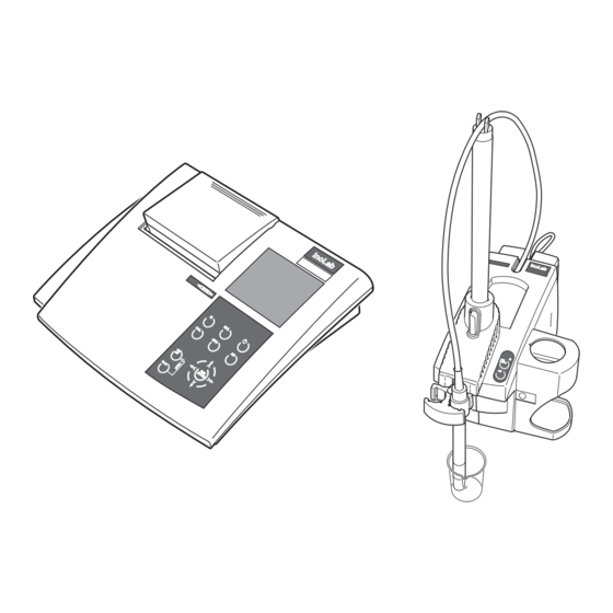
Page 20: Preparing The Inolab Level 3 Measuring System
Commissioning Preparing the inoLab Level 3 measuring system A measuring module that is ready for operation looks as follows: Cable holder Stand rod Opening to the cable shaft Connection cable to the terminal (AK M-T) Locking holder Beaker with test solution... - Page 21 Commissioning Perform the following activities before commissioning the system: Prepare the measuring module Connect the probe Connect the terminal Connect the plug-in power supply Connect the system upgrades Place the measuring module on a flat surface and Preparing the protect it from intense light and heat. module Insert the stand rod (2) into the measuring module.
- Page 22 Commissioning Connecting the Place the probe (8) into the probe holder (9). probe Place the cable (11) of the probe (8) into the cable holder (1) on the stand rod. Connections depending on the measuring module: pH/ORP electrode or ion-selective electrode D.
- Page 23 Commissioning Place the probe cable (11) into the cable shaft (3) so that it is stored safely. Connecting the Plug the connecting cable to the terminal (AK M-T) terminal into the socket (17). Place the terminal on a flat surface near the measuring module and protect it from intense light and heat.
- Page 24 Commissioning System upgrades Plug the external temperature probes into the sockets (15 and 16). Plug the StirrOx G oxygen probe with integrated stirrer into socket (14). Plug external printer/PC or recorder into socket (19). Connect the external PC keyboard or barcode reader via the adapter cable AK T-K PS2 to socket (20).
- Page 25 Fit the country-specific adapter (23) onto the plug-in power supply (24). Plug in the original WTW plug-in power supply (24) to an easily accessible wall socket. The system is in the standby mode. The display shows the date and time.
-
Page 26: Switching On The Measuring System
Commissioning Switching on the measuring system After the plug-in power supply unit is connected and the initializing period is over, the measuring system switches to standby mode (Standby and the date and time are displayed). When you want to measure, switch the system on. Place the terminal and measuring module on a flat surface and protect them from intense light and heat. - Page 27 Commissioning...
-
Page 28: Settings
Commissioning Settings To obtain the best results and to make use of the entire range of functions of the inoLab Level 3 measuring system, the measuring system must be configured and calibrated. You can adapt the configuration to your measuring environment and your requirements via system settings and probe-dependent settings. -
Page 29: Updating The Terminal Software (Firmware)
Commissioning Updating the terminal software (firmware) The program "Firmware Update inoLab Terminal Level3 Vx.x" is used to update the firmware of the inoLab Level 3 terminal. The newest firmware version can be downloaded from the Internet under www.wtw.com. Prerequisites: PC with Windows 95, 98, or NT operating system... -
Page 30: Starting The Update Of The Terminal Firmware
Commissioning 3.5.2 Starting the update of the terminal firmware Unplug the plug-in power supply and measuring module (active multifunction box) from the inoLab Level 3 terminal. Download the installation program for the firmware update, e.g. from the Internet. Start the installation program for the firmware update. The program creates an entry in the Windows start bar (in the standard installation under Start / Programme / Firmware Update inoLab Terminal V... - Page 31 Commissioning Plug the power supply into the inoLab Level 3 terminal again. The Standby display appears. Press and hold it down. Press [Offline]. Release both keys. The Terminal Programming window shows the current status of the update (in %). Wait for display to reach 100%.
- Page 32 Commissioning...
-
Page 33: Basic Principles Of Operation
Return to the Display mode by pressing or by pressing the [ESC] softkey several times. The inoLab Level 3 measuring system is operated via the terminal. The AutoRead function and starting a measurement with AutoRead can also be operated from the... -
Page 34: Display
Basic principles of operation Display The display shows measured values, active functions/ settings, available softkey functions and a selection of measuring and display settings in the menu. Menu Measured variable, measured value, measured temperature value, temperature probe Status display indicators Softkey functions Below the display there are three softkeys to perform the displayed softkey functions. - Page 35 Basic principles of operation Temperature probe is being used pH measurement only: Integrated temperature probe of a conductivity measuring cell is being used pH measurement only: Integrated temperature probe of a D. O. probe is being used D. O. measurement only: The salt content is taken into consideration.
-
Page 36: Softkey Functions
Basic principles of operation 4.1.2 Softkey functions The currently available softkey functions are displayed above the corresponding softkeys. Softkeys are displayed in italics and in square brackets, e.g. [Menu]. Prints the current display contents (right-hand softkey only) [Menu] Switches to the Menu mode (left-hand softkey only) [ESC] Switches to the next higher menu level in the... -
Page 37: Symbols In The Menu Mode
Basic principles of operation 4.1.3 Symbols in the Menu mode White script: White script (example: Baud rate 1200) on a black Function/setting selected background Black script Black script: on a white (example: Baud rate 2400) background Selectable function/setting; the function/setting can be selected by pressing Tick Tick ✔... -
Page 38: Display Of Measured Values
Basic principles of operation 4.1.4 Display of measured values The display shows measured values clearly by: Detailed display of a measured value Simultaneous display of two measured values Graphical representation of the course of a series of measurements Digital recorder display Display of a Example: measured value... - Page 39 Basic principles of operation Graphical Example: display Graphical display of a pH graph. Measurement datasets that you have stored with the AutoStore function (see section 11.1.2) can be displayed in the form of a graph. Sections of the graph can be zoomed. You can print out the current display.
-
Page 40: Keys
Basic principles of operation Keys The inoLab Level 3 measuring system has a keypad on the terminal and one on the measuring module. The two keys mentioned below are located both on the terminal and on the measuring module: key to activate the AutoRead function key to start a measurement with AutoRead. -
Page 41: Keys On The Terminal
Basic principles of operation 4.2.1 Keys on the terminal Three softkeys (display-dependent function keys). The currently available function of the key appears on the display above the key. Switches from the Menu to the Display mode or selects a measured variable Starts a calibration procedure Print LED (only on the terminal with integrated printer) -
Page 42: Keys On The Measuring Module
Basic principles of operation Activates/deactivates the AutoRead function Switches the measuring system on/off Displays/transmits measured values 4.2.2 Keys on the measuring module Status indicator of the AutoRead function LED off: AutoRead function is deactivated LED lights up: AutoRead function is activated LED flashes: AutoRead measurement has been started Starts the AutoRead measurement... -
Page 43: Ibm Pc Keyboard
Basic principles of operation 4.2.3 IBM PC keyboard You can also operate the measuring system via an external keyboard. This enables the input of letters, e.g. for assigning names as identification (ID). The keys on the terminal are positioned to correspond to the keys on the function block of an IBM PC keyboard. -
Page 44: Barcode Reader
Basic principles of operation 4.2.4 Barcode reader The entry of letters, e.g. for assignment of names as identification (ID) is also possible with a barcode reader. To connect a barcode reader to the terminal, you require the adapter cable AK T-K PS2. Menu The main menu line of the display contains four main menus. - Page 45 Basic principles of operation Change to the Menu mode with [Menu] . The last main menu used, e.g. Opt, is opened and the last menu item used, e.g. Setup, is selected. The [ESC] softkey is available. Active (✔) function Selectable function A submenu with further settings is available Using a menu...
- Page 46 Basic principles of operation Example Setting the temperature unit Starting point: pH measurement in the Display mode Change to the Menu mode with [Menu] . to select the main Opt menu. Select the Setup menu item with Confirm the Setup menu item with Select the Temp Unit menu item with...
- Page 47 Basic principles of operation Confirm the Temp Unit menu item with Using , confirm the Celsius or Fahren setting. Confirm the selected temperature unit with The selected temperature unit is active (✔). Terminate the Menu mode with The temperature unit is shown on the display.
-
Page 48: Output Of Measured Data
Basic principles of operation Output of measured data You can display measured values on the display graphically and numerically, and output them to a printer, an analog recorder, or a PC. 4.4.1 Measured data display on the screen Sample display Representation Numerical display Display of the current measured... -
Page 49: Measured Data Output On The Integrated Printer
Basic principles of operation 4.4.2 Measured data output on the integrated printer On a terminal with integrated printer, you can output all displays directly to the internal printer. In order to print measured data records, it is necessary to configure the printer. The detailed settings of the menu can be found in chapter 12 D ATA OUTPUT If the internal printer is switched on, start the output of... - Page 50 Basic principles of operation...
-
Page 51: System Settings
System settings System settings Date and time A real-time clock is integrated in the system. The date and time appear both on the display and in printouts. The clock is buffered against power failures by two batteries (for information on how to change the batteries, see section 13.1 M AINTENANCE Switch to the Menu mode. -
Page 52: Changing The Language
System settings Changing the language Switch to the Menu mode. Select the main Opt menu with Select the Setup menu item with Confirm the Setup menu item with Select the Language menu item with Confirm the Language menu item with Select the English or German language with Confirm the language selection with The language is activated (✔). -
Page 53: Display Settings
System settings Display settings To adjust the quality of the display to the ambient light, you can adjust the contrast of the display in 10 steps and switch on a background display illumination if necessary. 5.3.1 Display contrast Setting the display Switch to the Menu mode. -
Page 54: Display Illumination
System settings 5.3.2 Display illumination Switching the Switch to the Menu mode. display illumination Select the main Opt menu with on/off Select the Setup menu item with Confirm the Setup menu item with Select the Display menu item with Confirm the Display menu item with Select the BckLight menu item with Confirm the BckLight menu item with The display illumination is switched on (✔). -
Page 55: Acoustic Signals
System settings Acoustic signals You can select which events are to trigger an acoustic signal: Warning messages (Signal) When measuring range limits are exceeded (Limit) Each time a key with no function is pressed (no func) You can select several options at the same time. Selecting acoustic Switch to the Menu mode. -
Page 56: Temperature
System settings Temperature The temperature is very important for the reproducibility of measured values. You can select the unit of the temperature display. The temperature is determined automatically via an external temperature probe or a temperature probe integrated in the probe. It is also possible to enter measured temperature values manually. -
Page 57: Measuring The Temperature
System settings 5.5.2 Measuring the temperature For reproducible pH/ISE measurements, it is essential to measure the temperature. You have the following possibilities for measuring the temperature: The temperature probe integrated in the probe measures the temperature automatically Automatic measurement of the temperature by the integrated temperature measuring probe of another probe An external temperature probe (accessory) NTC30 or Pt1000 measures the temperature automatically... - Page 58 System settings Select the pH setup menu item with Confirm the pH setup menu item with Select the O2/Cond TP menu item with Confirm the O2/Cond TP menu item with The temperature measurement is active (✔). Terminate the Menu mode with appears on the display so you can check your setting.
- Page 59 System settings Call up the entry field for the temperature value with Option: Switch between the individual digits with Set up the temperature value with Confirm the temperature value with Terminate the input with [ESC]. The display shows the temperature value that was selected.
-
Page 60: User Profiles
System settings User profiles All documented measurement or calibration data are output together with the user name of the provider. User profiles contain the user name and the authorization assigned to the user. Name Access Authorization Admin protected to measure all measured by a variables password... - Page 61 The administration of user profiles is only possible if a user logs in with the user name, Admin. Note The user name Anonymous provides rapid access to the inoLab Level 3 measuring system without having to enter a password. The administrator can disable or enable this access (see section 5.6.3).
-
Page 62: Opening The Administration Menu
System settings 5.6.1 Opening the Administration menu Swap to standby mode with Swap to offline mode with [Offline]. Select the user name Admin with Confirm the user name with [OK]. Input the password for the user name with Confirm the password with [OK]. Access to the settings in the offline mode is opened. -
Page 63: Creating, Editing, Or Deleting A User Profile
System settings 5.6.3 Creating, editing, or deleting a user profile Enabling/disabling Open the Administration window (see section 5.6.2). the user profile, Select the user name Anonymous with Anonymous Select the user name Anonymous with [OK]. A prompt appears for changing the present setting. Select Yes with [Next]. - Page 64 System settings Note If no setting with the selected number is yet stored, a message appears when the user profile is stored. Save a setting (see section 11.2). It is not possible to log in with a user name without a valid setting.
-
Page 65: Printing The List Of User Profiles
System settings 5.6.4 Printing the list of user profiles The administrator (login with the user name, Admin) can print out a list of current user profiles or all user profiles. The list of current user profiles (Current) contains the user profiles which can be used for login. -
Page 66: Password For User Names
System settings Password for user names The login with the user name Admin and all self-created user names is protected by a password. Each terminal is delivered with the password "0001" for the user name, Admin. Change this password as soon as possible. -
Page 67: Assigning A Password
System settings 5.7.2 Assigning a password As long as no login has yet been made with a new user name, this user name is displayed in brackets in the list of user names. The user specifies the password when he first logs in with the new user name. -
Page 68: Forgotten The Password
In emergencies, it is also possible to log in with the user name Admin using a special enabling code obtained from WTW GmbH & Co. KG. The address and telephone number of WTW GmbH & Co. KG is given on the cover page of this operating manual. -
Page 69: Modules
System settings Modules The calibration data can only be assigned to a user name if the calibration data were recorded with the current combination of terminal and module. As a result of the registration of the modules, the terminal recognizes whether the calibration data were stored in the module with this or another terminal. - Page 70 System settings Open the Administration menu (see section 5.6.1). Select the Module menu item with Confirm the Module menu item with [OK]. The Module register window opens. Deleting a module Select a Module menu item with Delete the selected Module with [X] Print out the list of registered modules Print out the list of Modules with [PRINT].
-
Page 71: Settings For Ph
We recommend checking the current settings and correcting them if necessary before a measurement. 6.1.1 Displaying pH/ISE or measured voltage values For pH measurements, the inoLab Level 3 enables rapid switching between the display of the pH value (pH) and the voltage (U). Activate the Display mode. -
Page 72: Setting The Ph Display
6.1.2 Setting the pH display pH electrodes are connected to the same connector on the measuring module. The selection of the measured variable ISE or pH is made in the main Meas menu. The active pH or ISE setting is marked with ✔. -
Page 73: Measured Value Resolution Of Voltage Display
6.1.3 Measured value resolution of voltage display Using the U-AutoRng function, you can select the resolution of the voltage measurement: If U-AutoRng is not active, voltages in the range of -1999 to +1999 mV are measured with a resolution of 1 mV. If U-AutoRng is active, voltages in the range of +999.9 mV to -999.9 mV are measured with a resolution of 0.1 mV. -
Page 74: Measured Value Resolution Of Ph Display
6.1.4 Measured value resolution of pH display You can select the resolution for the pH value: If the high resolution (pH high resol. ✔) is switched on, measurement is carried out over the entire pH range with the smallest possible resolution of 0.001. If the high resolution (pH high resol.) is switched off, measurement is carried out over the entire pH range with a resolution of 0.01. -
Page 75: Resetting To Default Settings
6.1.5 Resetting to default settings You can reset (initialize) the settings for the pH measurement to the default settings. In a reset, the following functions for the pH measurement are reset to the default settings: Measuring mode Asymmetry U in mV 0 mV Slope S (k) in mV -59.16 mV... -
Page 76: Calibrating Ph Measurements
Calibrating pH measurements Why calibrate? pH electrodes age. This changes the asymmetry and slope of the pH electrode. This may cause the measuring system to ignore the limits of a calibrated system. Calibration determines the current values of the asymmetry and slope and stores them in the measuring module. - Page 77 Sample printout: pH calibration Cal Date: 05.12.1999 Cal Time: 22:46 Cal Interval: 7 days AutoCal TEC Tman AR Buffer 1 2.00 Buffer 2 4.01 Buffer 3 7.00 Buffer 4 10.00 290.6 mV 25°C 174.5 mV 25°C 0.2 mV 25°C -174.6 mV 25°C -58.2mV/pH 0 mV...
-
Page 78: Buffer Sets
You can use the following buffer sets at the specified temperatures for an automatic calibration. Buffer set Menu designati values temp WTW technical buffer Buffer 2.00 25 °C solutions 4.01 7.00 10.00... - Page 79 Selecting the Switch to the Menu mode. calibration to select the main Cal menu. procedure Select the pH caltype menu item with Confirm the pH caltype menu item with to select the AutoCal or ConCal menu item. Confirm the selected menu item with The selected calibration procedure is active (✔).
- Page 80 Calibration interval The calibration interval determines the time interval between regular system calibrations. The terminal reminds you to calibrate regularly by the flashing probe symbol on the display. The calibration interval is set to 7 days in the factory. You can change the interval (1-999 days).
-
Page 81: Calibration
6.2.2 Calibration Preparatory and/or to display the pH value. activities Connect the pH electrode to the measuring module. Keep the buffer solutions ready (up to 5 solutions, depending on the selected calibration procedure). Adjust the temperature of the solutions and measure the temperature if measurement is made without a temperature probe. - Page 82 The following example covers the autocalibration procedure using WTW technical buffer solutions. If you use other buffer solutions, e. g. DIN buffers or buffer solutions of the Merck company, the displays before using the next buffer will be different. Note During calibration, always use the pH buffer solutions in ascending order.
- Page 83 Thoroughly rinse the electrode with deionized water. If necessary, set the temperature of the second buffer solution with (see section 5.5.1). Immerse the electrode and the temperature probe in the second buffer solution. Start the measurement with display indicator flashes. The electrode voltage (mV) appears on the display.
- Page 84 Thoroughly rinse the electrode with deionized water. Three-point calibration If necessary, set the temperature of the third buffer solution with (see section 5.5.1). Immerse the electrode and the temperature probe in the third buffer solution. Press the key. display indicator flashes. The electrode voltage (mV) appears on the display.
- Page 85 Press the key. display indicator flashes. The electrode voltage (mV) appears on the display. As soon as a stable value is reached, disappears. The probe symbol shows the calibration evaluation after the four-point calibration. The value of the slope S (in mV/pH) and the value of the asymmetry U (in mV) appear on the display.
- Page 86 ConCal Only one buffer solution is required for single-point single-point calibration. The pH value should lie as close as possible to calibration the expected measured value. Only the electrode asymmetry is then newly determined. The slope of the last two-point calibration is retained. ConCal Use the following buffer solutions: two-point calibration...
- Page 87 to display the slope (mV/pH), the asymmetry (mV), and the calibration evaluation (probe symbol). to go on to the two-point calibration or terminate after the single-point calibration with (the present calibration data remain stored). Two-point Thoroughly rinse the electrode with deionized water. calibration Immerse the electrode and the temperature probe in the second buffer solution.
- Page 88 Press the key. The calibration is finished. Note After the calibration is finished, the calibration record is automatically printed if the printer is ready for operation. Information on setting up a printer and on the printout of further calibration protocols is given in chapter 12 D and section 12.2.4 P OUTPUT RINTING...
-
Page 89: Measuring The Ph Value
Measuring the pH value Preparatory Perform the following preparatory activities when you want activities to measure: Connect the electrode to the measuring module. Call up the Display mode with Call up the pH measured value display with Adjust the temperature of the solutions and measure the current temperature if the measurement is made without a temperature probe. - Page 90 Immerse the pH electrode in the test sample. The display shows the current measured value. AutoRead The AutoRead function (drift control) checks the stability of (drift control) the measurement signal. The stability has a considerable effect on the reproducibility of the measured value. With identical measuring conditions, the maximum deviation is 0.02.
-
Page 91: Measuring The Orp Voltage
Measuring the ORP voltage The measuring system can measure the voltage of a solution in conjunction with a ORP electrode, e.g. SenTix ORP. Call up the Display mode with Call up the measured variable U with Submerse the ORP electrode in the sample. Wait for a stable measured value. -
Page 93: Ion Concentration
We recommend checking the current settings and correcting them if necessary before a measurement. 7.1.1 Displaying pH/ISE or measured voltage values In pH/ISE measurements, inoLab Level 3 enables a rapid changeover between the display of the pH/ISE value (pH) and voltage (U). Activate the Display mode. -
Page 94: Measured Value Resolution Of Voltage Display
Ion concentration Confirm the ISE menu item with The ISE display is active (✔). Terminate the Menu mode with The ion concentration appears on the display (mg/l). 7.1.3 Measured value resolution of voltage display See section 6.1.3 7.1.4 Resetting to default settings No default settings are specified for ion-selective measurements. -
Page 95: Advanced Settings For Ise
Ion concentration Advanced settings for ISE For the inoLab Level 3 pH/ION measuring module. 7.2.1 Units of the ISE display You can select the units of the measured value: Switch to the Menu mode. to select the main Meas menu. -
Page 96: Blank Value Correction (Bw Corr)
Ion concentration If mg/kg, ppm, % was selected: Enter the density of the sample with Continue with step 13. Confirm the entry with or [ESC]. The units change over. Switch to the measured value display. 7.2.2 Blank value correction (Bw Corr) If the ion concentration in the sample is so small that it does not lie in the linear range of the electrode, you can increase the ion concentration in the linear range with the blank value... - Page 97 Ion concentration Thoroughly rinse the electrode with deionized water. Immerse the electrode in the blank value solution. Select Yes with [Next]. Confirm Yes with g. Terminate the blank value determination with [ESC]. symbol no longer flashes. The displayed measured value is reduced by the blank value. The blank value correction is active until the blank value is switched off.
-
Page 98: Reference Measurement (Ref Meas)
Ion concentration 7.2.3 Reference measurement (Ref Meas) A reference measurement enables you to assign the voltage value 0 mV to the calibration curve of your electrode for a specific ion concentration (reference concentration). Prerequisite: The measured value display must show the voltage. A valid calibration must be available. - Page 99 Ion concentration Select the input field R with [Next]. Enter the reference concentration R with Use [ESC] to leave the input field. The measured voltage value is referred to the new reference concentration.
-
Page 100: Criterion For Autoread (Autoread)
Ion concentration 7.2.4 Criterion for AutoRead (AutoRead) The AutoRead criteria affect the reproducibility of the measured values. The following criteria can be adjusted: high: highest reproducibility medium: medium reproducibility low: lowest reproducibility Note Increasing reproducibility also causes the response time to increase until a measured value is evaluated as stable. -
Page 101: Calibration For Ion-Selective Measurements
Ion concentration Calibration for ion-selective measurements Why calibrate? Ion-selective electrodes age and are temperature- dependent. This changes the slope. Calibration determines the current slope of the electrode and stores it in the measuring system. Thus, you should calibrate before each measurement and at regular intervals. - Page 102 Ion concentration Calibration record The calibration record contains the calibration data of the current calibration. You can call up the calibration record by outputting the data storage (section 11.3). Note You can automatically print a calibration record following calibration. To do so, switch on the printer before calibrating (print LED lights up green).
- Page 103 Ion concentration Preparatory Perform the following preparatory activities: activities Switch on the measuring system with Connect the electrode to the measuring module. Connect a temperature probe to the measuring system so that any temperature differences that are too high will be indicated during calibration. Keep the standard solutions ready.
- Page 104 Ion concentration Calibration Use two or three different standard solutions. For the three- point calibration, the standard solutions have to be selected in either increasing or decreasing order. Standard Values [mg/l] solution Std 1 0.01; 0.02; 0.05; 0.1; 0.2; 0.5; 1; 2; 5; 10; 20; 50;...
-
Page 105: Two-Point And Three-Point Calibration
Ion concentration 7.3.1 Two-point and three-point calibration Two-point Perform the preparatory activities. calibration Switch to the ISE display with and/or Press the key. A field to select the concentration of the first standard solution is displayed. to enter the concentration of the first standard solution. - Page 106 Ion concentration to enter the concentration of standard solution 2. Thoroughly rinse the electrode with deionized water. Immerse the electrode in standard solution 2. Press the key. The electrode voltage is displayed and the display indicator flashes. As soon as a stable value is reached, stops flashing.
- Page 107 Ion concentration to finish the calibration. Continue to the three-point calibration with Note The calibration curve after the two-point calibration is determined by linear regression# The values of the two- point calibration are then stored. Three-point Press the key. calibration The previously set up concentration of the third standard solution appears on the display.
- Page 108 Ion concentration As soon as a stable value is reached, stops flashing. The slope (mV) of the electrode is displayed. The probe symbol shows the electrode evaluation after the previous calibration. to finish the calibration. In the case of the pH/ION measuring module: Continue to the four-point to six-point calibration with (see section 7.3.2).
-
Page 109: Four-Point To Six-Point Calibration
Ion concentration 7.3.2 Four-point to six-point calibration For the inoLab Level 3 pH/ION measuring module. Beyond the three-point calibration, a four-point, five-point or six-point calibration is also possible in the pH/ION measuring module. Use different standard solutions for this. The standard solutions have to be selected in either increasing or decreasing order. - Page 110 Ion concentration to enter the concentration of the fourth standard solution. Thoroughly rinse the electrode with deionized water. Immerse the electrode in the next standard solution. Press the key. The electrode voltage is displayed and the display indicator flashes. As soon as a stable value is reached, stops flashing.
- Page 111 Ion concentration For carrying out a multipoint calibration: Repeat steps 2 - 7 To return to the measuring mode: Press the key. Note You can also terminate the calibration prematurely with The values of the previous calibration the remain stored. The calibration curve is determined by spline interpolation.
-
Page 112: Measuring The Ion Concentration
Ion concentration Measuring the ion concentration Preparatory Perform the following preparatory activities when you want activities to measure the concentration using ion-sensitive electrodes: Connect the electrode to the measuring module. Adjust the temperature of the solutions, or measure the temperature if the measurement is made without a temperature probe. - Page 113 Ion concentration Measuring Measure the concentration as follows: the concentration Perform the preparatory activities according to section 7.4 Immerse the electrode in the test sample. Press the key until ISE appears. The concentration value appears on the display. AutoRead The AutoRead function (drift control) checks the stability of (drift control) the measurement signal.
- Page 114 Ion concentration In order to accept the current measured value without waiting for the end of the AutoRead function, press...
-
Page 115: Select The Measuring Method
Ion concentration 7.4.1 Select the measuring method For the inoLab Level 3 pH/ION measuring module. The following methods are supported: Standard Addition (Std Add) Double Standard Addition (Std Add ++) Standard Subtraction (Std Sub) Sample Addition (Smp Add) Sample Subtraction (Smp Sub) -
Page 116: Standard Addition (Std Add)
Ion concentration Select the ISE Adv. menu item with Confirm the ISE Adv. menu item with The menu with the measuring methods opens. Select a method with Confirm the method with Measurement with the selected method begins. 7.4.2 Standard Addition (Std Add) In the "Standard addition"... - Page 117 Ion concentration Measuring Start the measurement with [Start]. A window for the entry of data opens. Enter Sample volume and ISA/TISAB volume with and [Next]. Thoroughly rinse the electrode with deionized water. Immerse the electrode in the sample. Start the measurement with [Start]. Add the standard solution to the sample.
- Page 118 Ion concentration Enter Standard volume, Standard concentration and Ion type with and [Next]. Terminate the measurement with [Start]. Start a new measurement with [Next]. Repeat steps 7 - 13 for all samples. Terminate the measurement with [ESC]. A security prompt appears. Select Yes with [Next].
-
Page 119: Double Standard Addition (Std Add ++)
Ion concentration 7.4.3 Double Standard Addition (Std Add ++) In the "Double Standard Addition" procedure, a known amount of standard solution is added to the sample in two steps. The ion concentration in the sample is calculated from the change in potential between the first and second addition of standard solution. - Page 120 Ion concentration Add standard solution (1 Vol.% of the sample solution). Start the measurement with [Start]. A window for the entry of data opens. Enter Standard volume, Standard concentration and Ion type with and [Next]. Continue the measurement with [Start]. Add the standard solution (2 Vol% of the sample solution).
- Page 121 Ion concentration Start a new measurement with [Next]. Repeat steps 1 - 12 for all samples. Terminate the measurement with [ESC]. A security prompt appears Select Yes with [Next]. Confirm Yes with The measurement is terminated.
-
Page 122: Standard Subtraction (Std Sub)
Ion concentration 7.4.4 Standard Subtraction (Std Sub) In the "Standard Subtraction" procedure, a known amount of standard solution is added to the sample (as complexing agent or precipitating agent) and, thus, the ion concentration lowered. The ion concentration in the sample is calculated from the change in potential. - Page 123 Ion concentration Enter Sample volume and ISA/TISAB volume with and [Next]. Thoroughly rinse the electrode with deionized water. Immerse the electrode in the sample. Start the measurement with [Start]. Add the standard solution to the sample. Start the measurement with [Start]. A window for the entry of data opens.
- Page 124 Ion concentration Enter Standard volume, Standard concentration and Ion type for the sample (#1) and standard solution (#2) with and [Next]. For the entry of a self-defining type of ion (??): Select the ?? entry for the ion in the sample (#1) with Set the valency and molecular weight for the ion in the sample with [Next] and...
-
Page 125: Sample Addition (Smp Add)
Ion concentration 7.4.5 Sample Addition (Smp Add) In the "Sample addition" procedure, a known amount of sample is added to the standard solution. The ion concentration in the sample is calculated from the change in potential. Select the measuring method (see section 7.4.1). Prepare two standard calibration solutions. - Page 126 Ion concentration Enter Standard volume, Standard concentration and ISA volume with and [Next]. Thoroughly rinse the electrode with deionized water. Immerse the electrode in the standard. Start the measurement with [Start]. Add the sample to the standard solution. Start the measurement with [Start]. Enter Standard volume, Standard concentration and ISA volume with and [Next].
-
Page 127: Sample Subtraction (Smp Sub)
Ion concentration Terminate the measurement with [Start]. Start a new measurement with [Next]. Repeat steps 5 - 14 for all samples. Terminate the measurement with [ESC]. A security prompt appears Select Yes with [Next]. Confirm Yes with The measurement is terminated. 7.4.6 Sample Subtraction (Smp Sub) In the "Sample Subtraction"... - Page 128 Ion concentration Select the measuring method (see section 7.4.1). Prepare two standard calibration solutions. Perform a two-point calibration according to user guidance. As soon as a stable value for the second standard calibration solution is reached, the display indicator stops flashing. The slope (mV) of the electrode is displayed after the two-point calibration.
- Page 129 Ion concentration Start the measurement with [Start]. Add the standard solution to the sample. Start the measurement with [Start]. Enter the Standard volume, and the Ion type for the sample (#1) and standard solution (#2) with [Next]. For the entry of a self-defining type of ion (??): Select the ?? entry for the ion in the sample (#1) with Set the valency and molecular weight for the ion in...
- Page 130 Ion concentration Start a new measurement with [Next]. Repeat steps 5 - 15 for all samples. Terminate the measurement with [ESC]. A security prompt appears Select Yes with [Next]. Confirm Yes with The measurement is terminated.
-
Page 131: Standard Addition With Blank Value Correction (Bw Add)
Ion concentration 7.4.7 Standard addition with blank value correction (Bw Add) In the "Standard addition with blank value correction" procedure, a known amount of standard solution is added to the sample in two steps. The ion concentration in the linear range of the electrode characteristic curve is increased with the first addition. - Page 132 Ion concentration Measuring Start the measurement with [Start]. A window for the entry of data opens. Enter the volume of the sample (Smp Vol), volume of the ISA solution (ISA Vol), volume of the blank value solution (Bw Vol) and concentration of the blank value solution (Bw Conc) with and [Next].
- Page 133 Ion concentration Enter the volume of the standard solution (Std volume), concentration of the standard solution (Std conc.) and Ion typewith and [Next]. Terminate the measurement with [Start]. Start a new measurement with [Next]. Repeat steps 5 - 14 for all samples. Terminate the measurement with [ESC].
- Page 134 Ion concentration...
-
Page 135: Dissolved Oxygen (D. O.)
Dissolved oxygen (D. O.) Dissolved oxygen (D. O.) Measuring modules for the inoLab Level 3: Oxi, BSB/BOD, pH/Oxi and Multi. Settings for D. O. measurements In order to achieve comparable and reproducible measuring results, we recommend checking the current settings before measuring. -
Page 136: Displaying The Air Pressure
Dissolved oxygen (D. O.) Confirm the AutoRng menu item with display indicator appears on the display. Terminate the Menu mode with 8.1.2 Displaying the air pressure You can display the current air pressure in mbar. Note The value always shows the absolute air pressure. It does not refer to altitude above sea level. -
Page 137: Salinity Correction
Dissolved oxygen (D. O.) Press [ESC] to close the air pressure display and terminate the Menu mode. 8.1.3 Salinity correction When measuring the concentration of test samples with a salt content of more than 1 g/l, a salinity correction is required. - Page 138 Dissolved oxygen (D. O.) Switching the You can switch the salinity correction on/off. The display salinity correction indicator appears on the display when the salinity correction on/off is switched on. Switch to the Menu mode. to select the main Meas menu. Select the Include sal menu item with Confirm the Include sal menu item with The salinity correction is active (✔).
-
Page 139: Resetting To Default Settings
Dissolved oxygen (D. O.) 8.1.4 Resetting to default settings You can reset (initialize) the settings for the D. O. measurement to the default settings. The following functions are reset: Measuring mode D. O. concentration Relative slope (S 1.00 Salinity (value) Salinity (function) Reset O2 With the O2 reset, all the settings for D. -
Page 140: Calibrating For D. O. Measurements
Dissolved oxygen (D. O.) Calibrating for D. O. measurements Why calibrate? D. O. probes age. This changes the slope of the D. O. probe. As a result, an inexact measured value is displayed. Calibration determines the current slope of the probe and stores this value in the instrument. - Page 141 Dissolved oxygen (D. O.) Sample printout: Calibration O2 Cal Date: 05.12.1999 Cal Time: 22:46 Cal Interval: 14 days OxiCal Rel. slope 0.73 Sensor +++ User: xxxxx Probe evaluation After the calibration, the measuring module evaluates the current status, i. e. the relative slope, of the probe. The evaluation appears on the display.
-
Page 142: Settings
Dissolved oxygen (D. O.) 8.2.1 Settings Calibration interval The calibration interval is used to determine after how many days you want to be reminded that a D. O. calibration is due. Switch to the Menu mode. to select the main Cal menu. Select the Cal Int. - Page 143 Dissolved oxygen (D. O.) Put the D. O. probe into the air calibration vessel. Press the key. Press the key. flashes until a stable value is reached. The probe symbol shows the relative slope that has been determined and the probe evaluation (see page 141).
-
Page 144: Measuring The D. O. Content
Dissolved oxygen (D. O.) Measuring the D. O. content You can display the following measured parameters: D. O. concentration Oxygen saturation Oxygen partial pressure Preparatory Preparatory activities before the measurement: activities Connect the D. O. probe to the measuring module. The measuring system identifies the probe and displays a measured value for oxygen. -
Page 145: Selecting The Measured Value Display
Dissolved oxygen (D. O.) Immerse the D. O. probe in the test sample. The measured variable last selected appears on the display. 8.3.1 Selecting the measured value display Press the key repeatedly until the oxygen D. O. concentration concentration appears on the display in mg/l. D. -
Page 146: Drift Control (Autoread)
Dissolved oxygen (D. O.) 8.3.2 Drift control (AutoRead) The AutoRead function checks the stability of the measurement signal. The stability has a considerable impact on the reproducibility of the measured values. When using a probe with integrated stirrer (StirrOx G), the measurement with AutoRead can be started using the key on the probe. - Page 147 Dissolved oxygen (D. O.) Note In order to accept the current measured value without waiting for the end of the AutoRead function, simply press on the terminal or measuring module or the key on the StirrOx G probe. Reproducibility With identical measurement conditions, the following criteria applies: Measured...
- Page 148 Dissolved oxygen (D. O.)
-
Page 149: Bod
For the inoLab Level 3 BSB/BOD measuring module. General information For BOD measurements, the inoLab BSB/BOD enables: The administration of a maximum of 30 samples. The use of a maximum of 18 sample dilutions per sample. The use of a maximum of 5 blank value solutions (for determination of the blank value). -
Page 150: Operation With The Stirrox G Oxygen Sensor
Preparatory Preparatory activities before the measurement: activities Prepare blank value solutions and sample dilutions. Calibrate or check the measuring system with the probe (see section 8.2). Note An incorrect calibration of the measuring system with D. O. probes will cause incorrect measured values. Perform a calibration at regular time intervals (see section 8.2). - Page 151 Confirm the BOD menu item with Select the BOD setup menu item with Confirm the BOD setup menu item with Select the Scanner menu item with Confirm the Scanner menu item with The selection field for the scanner setting appears. Select the required use of the barcode reader (automatic or manual) with Confirm the settings with [ESC].
-
Page 152: Bod Measurement
BOD measurement 9.2.1 Procedure BOD measurements run according to the following sequence: Start measurement at the beginning of the incubation period – Measurement of the blank value solutions – Measurement of the sample dilutions End measurement after expiry of the incubation period –... - Page 153 Switch to the Menu mode. to select the main Meas menu. Select the BOD menu item with Confirm the BOD menu item with Select the Start Meas menu item with Confirm the Start Meas menu item with The Start measurement window appears. To start a measurement without routine, continue at step 7.
- Page 154 Swap between the entry fields with [Next]. Only for New dilution water Yes: Enter the number of the blank value solutions to be measured in the Number field with Only for New dilution water Yes: Swap between the entry fields with [Next]. Select the incubation period (in days) in the BOD field with Confirm the settings with [Start].
- Page 155 Select a routine name with Swap between the entry fields with [Next]. Select Yes or No in the Dilution water field with If New dilution water No was selected: The Number entry field disappears. The measurement of the blank value solutions is skipped. The blank value solutions last measured are used for the BOD determination.
- Page 156 Measurement of Check the data on the display. blank value If the data is correct: Continue with step 24. solutions To change the data: Continue with step 23. Enter a name with , external keyboard or barcode reader. Immerse the sensor in the blank value solution. Start the measurement with [Start].
- Page 157 Measurement of Check the data on the display. sample dilutions If the data is correct: Continue with step 32. To change the data: Continue with step 29. Enter a name for the sample dilution with , an external keyboard or via the barcode reader. Swap between the entry fields with [Next].
- Page 158 Enter the total volume of the sample dilution in the Vol.Total field with or an external keyboard. Immerse the sensor in the sample dilution. Start the measurement with [Start]. The sample dilution is measured. Wait for the end of the measurement. Repeat from step 33 to step 42 for all sample dilutions.
-
Page 159: Stopping The Bod Measurement
Saving the routine Swap between the entry fields with [Next]. Enter a name for the routine with or an external keyboard. Confirm the entry with [Ok]. The start measurement is completed and the data are stored as a routine using the name entered. 9.2.3 Stopping the BOD measurement You can stop the measurement process at any time during... -
Page 160: End Measurement
9.2.4 End measurement The end measurement is carried out after the incubation period expires. Note Normally, you can confirm all windows and settings in the end measurement by simply pressing [Start]. The settings and values offered correspond to the values that were entered in the start measurement. - Page 161 Select a sample in the name field with The status field shows the status of the sample: : incubation period still running : performing end measurement : end measurement already performed. : incubation period exceeded Check the data on the display. If the data is correct: Continue with step 11.
- Page 162 sample dilutions is acceptable. Reading in the identification automatically causes the correct assignment of the start measurement to the measured value. In an end measurement without a barcode reader, follow the prescribed order of the measurements. Check the data on the display. If the data is correct: Continue with step 16.
- Page 163 Wait for the end of the measurement. Repeat from step 12 to step 18 for all blank value solutions. Subsequently, the End measurement window opens for the sample dilutions. Check the data on the display. If the data is correct: Continue with step 23. To change the data: Continue with step 20.
- Page 164 Wait for the end of the measurement. Repeat from step 19 to step 24 for all sample dilutions. Subsequently, the End status BOD window opens. Display and edit the measurement result with [Open] (see section 9.3.1) Terminate the end measurement with [ESC].
-
Page 165: Bod Result
BOD result 9.3.1 Displaying, editing and printing the measurement result After the end measurement is completed, you can display, edit and print out the measurement result. The editing is restricted to the IDs of blank value solutions and sample dilutions that are not included in the calculation. Displaying the Switch to the Menu mode. - Page 166 View the measured data with (a small arrow on the left edge of the display shows the selected line). Editing the Select a line containing a measured value with measurement result small arrow on the left edge of the display shows the selected line).
- Page 167 Sample printout: 14.03.2001 16:04:53 ======================================= BOD 5 report Sample ID _______________________________________ Start measurement from 14.03.2001 14:02:29 14.03.2001 14:03:38 Final measurement from 19.03.2001 15:03:35 19.03.2001 15:04:44 Dilution water _______________________________________ Start 7.87 mg/l 7.15 mg/l Blank value 0.72 mg/l Start 7.87 mg/l 7.87 mg/l Blank value 0.00 mg/l...
-
Page 168: Deleting Bod Measurement Results
9.3.2 Deleting BOD measurement results Deleting individual Switch to the Menu mode. BOD measurement to select the main Meas menu. results Select the BOD menu item with Confirm the BOD menu item with Select the Delete BOD menu item with Confirm the Delete BOD menu item with Select the Sample menu item with Confirm the Sample menu item with... - Page 169 Deleting all BOD Switch to the Menu mode. measurement to select the main Meas menu. results Select the BOD menu item with Confirm the BOD menu item with Select the Delete BOD menu item with Confirm the Delete BOD menu item with Select the All samples menu item with Confirm the All samples menu item with The security prompt opens.
-
Page 170: Routines
Routines 9.4.1 Setting up routines Routines define constantly recurring measurement procedures. This includes the number and name of blank value solutions and sample dilutions as well as the dilution ratios. Routines are set up Before the first measurement: Complete routines can be set up in the BOD menu. At the end of a start measurement: You can save the current settings as a routine in the Save routine window. - Page 171 Switch to the Menu mode. to select the main Meas menu. Select the BOD menu item with Confirm the BOD menu item with Select the BOD setup menu item with Confirm the BOD setup menu item with Select the New routine menu item with Confirm the New routine menu item with The Start measurement window appears.
-
Page 172: Starting A Measurement With Routine
9.4.2 Starting a measurement with routine When using the routines for measurement, the fields on the display are already filled out with the data from the routine. This simplifies operation during the measurement to confirming the individual window with [Start]. With the exception of selecting a routine, the course of the measurement does not differ from the start measurement without routine. - Page 173 Select Yes with [Next]. Confirm the deletion of the routine with The display shows that the selected routine has been successfully deleted. Deleting all routines Switch to the Menu mode. to select the main Meas menu. Select the BOD menu item with Confirm the BOD menu item with Select the Delete BOD menu item with Confirm the Delete BOD menu item with...
-
Page 175: Conductivity
Conductivity Conductivity Measuring modules for the inoLab Level 3: Cond, pH/Cond and Multi. 10.1 Settings for conductivity measurements In order to achieve comparable and reproducible measuring results, we recommend checking and, if necessary, correcting the current settings before measuring. 10.1.1 Determining the measuring range You can select the measuring range manually or have it selected automatically. - Page 176 Conductivity Manual selection The AutoRng function has to be switched off for the manual of the measuring selection of the measuring range. range Switch to the Display mode. to select the required range or Sal or TDS. Automatic switch- Switch to the Menu mode. over to select the main Meas menu.
-
Page 177: Entering The Reference Temperature
Conductivity 10.1.2 Entering the reference temperature You can select the reference temperature T = 25°C (Tref25) or T = 20°C (Tref20). Switch to the Menu mode. to select the main Meas menu. Select the Cond setup menu item with Confirm the Cond setup menu item with Select the TRef25 or TRef20 menu item with Confirm the TRef25 or TRef20 menu item with Terminate the Menu mode with... -
Page 178: Displaying The Conductivity Or Specific Resistance
Conductivity 10.1.3 Displaying the conductivity or specific resistance You can select the display of the conductivity (in S/cm) or of the specific resistance (in MΩ cm). Switch to the Menu mode. to select the main Meas menu. Select the Cond setup menu item with Confirm the Cond setup menu item with Select the Cond MOhm menu item with Confirm the Cond MOhm menu item with... -
Page 179: Setting The Temperature Compensation
Conductivity 10.1.4 Setting the temperature compensation The calculation of the temperature compensation is based on the preset reference temperature, Tref 20 or Tref 25 (see chapter 10.2 D ETERMINING SETTING UP THE CELL CONSTANT You can select the following temperature compensations for the temperature functions: Nonlinear temperature compensation "nLF"... -
Page 180: Reset (Reset)
Conductivity Setting the Switch to the Menu mode. temperature to select the main Meas menu. compensation to select one of the menu items, TC nLF or TC lin or TC off. Confirm the selected menu item with The temperature compensation is active (✔). Terminate the Menu mode with 10.1.5 Reset (Reset) You can reset (initialize) the settings for the conductivity... - Page 181 Conductivity Switch to the Menu mode. to select the main Cal menu. Select the Reset cond menu item with to confirm the Reset cond menu item. The default settings for conductivity measurements are restored. The Menu mode is terminated. Note The calibration data will be lost in a reset.
-
Page 182: Determining/Setting Up The Cell Constant
Conductivity 10.2 Determining/setting up the cell constant Why determine/set Aging slightly changes the characteristics of the cell, e. g. by up the cell coatings. As a result, an inexact measured value is constant? displayed. The original characteristics of the cell can often be restored by cleaning the cell. - Page 183 Conductivity Calibration To determine the cell constant, you need a 0.01 mol/l KCl procedure calibration solution. Start the determination of the cell constant with Immerse the measuring cell in the prepared calibration solution. Press the key in order to start the measurement with AutoRead to determine the cell constant.
- Page 184 Conductivity Calibration After calibrating, the measuring module automatically evaluation evaluates the calibration. The evaluation appears on the display. Display Cell constant [cm 0.450 ... 0.500 cm 0.800 ... 1.200 cm outside the ranges 0.450 ... 0.500 cm Eliminate the error according to chapter 0.800 ...
- Page 185 Conductivity Calibration interval The calibration interval is used to determine after how many days you want to be reminded that a conductivity calibration is due. Switch to the Menu mode. to select the main Cal menu. to select the Cal Int..menu item. to confirm the Cal Int.
-
Page 186: Setting The Cell Constant
Conductivity 10.2.2 Setting the cell constant Note The cell constant to be set must either be taken from the operating manual of the measuring cell or is printed on the measuring cell. The inoLab 3 measuring system offers the following possibilities of setting the cell constant: Accepting the cell constant from the last calibration record (Cal cell) - Page 187 Conductivity Accepting the cell Accept the cell constant of the last calibration record as constant of the follows: calibration record Switch to the Menu mode. to select the main Cal menu. Select the Cell const. menu item with Confirm the Cell const. menu item. Select the Cal cell menu item with Confirm the Cal cell menu item with The cell constant of the last calibration is accepted.
- Page 188 Conductivity Confirm the Man cell menu item with The input field for the cell constant opens. The current value is displayed. Increase/reduce the value with Use [ESC] to leave the input field. Confirm the selected cell constant with The selected cell constant is accepted. Man cell is active (✔).
- Page 189 Conductivity Selecting the cell You can set the cell constant to the fixed value of 0.1 cm or 0.01 cm constant 0.1 cm 0.01 cm Switch to the Menu mode. to select the main Cal menu. Select the Cell const. menu item with Confirm the Cell const.
-
Page 190: Measuring The Conductivity
Conductivity 10.3 Measuring the conductivity 10.3.1 General information You can display the following measured parameters: Conductivity/specific resistance (For details of how to switch over, see chapter 10.1 S ETTINGS FOR CONDUCTIVITY MEASUREMENTS Salinity (Sal) Total dissolved solids (TDS) Preparatory Perform the following preparatory activities when you want activities to measure: Connect a conductivity measuring cell with... - Page 191 Conductivity Press the key until the measured variable, conductivity, ( ) appears. The measured value appears on the display. Press the key until the measured variable, Sal, appears. The salinity value appears on the display. Press the key until the measured variable, TDS, appears.
-
Page 192: Drift Control (Autoread)
Conductivity 10.3.3 Drift control (AutoRead) The drift control function (AutoRead) checks the stability of the measured value. The stability has a considerable effect on the reproducibility of the measured value. Select the required measuring mode with Immerse the conductivity measuring cell in the test sample. -
Page 193: Data Storage
Data storage Data storage Data storage enables the storage and administration of measurement, configuration and calibration data. The following types of storage are available: Storage of measurement data records: This memory contains measurement data records for subsequent processing or output (see section 11.1) Storage for system configurations (settings): This memory enables you to save and recall individual configurations (see section 11.2) -
Page 194: Storage Of Measurement Data Records
Data storage 11.1 Storage of measurement data records Measurement data record memory enables the storage of measurement data records for subsequent processing or output. There are two methods of storing measurement data records: Manual storage of individual measurement data records Automatic storage of several measurement data records A measurement data record consists of: Number of the storage location (Mem no.) - Page 195 Data storage Use [Ident] to open the Ident input window. Input the required name (ID) with With confirm the ID. In the manual type of storage, the measurement data record is stored together with the selected ID. Use [ESC] to leave the Ident input window. The Store window shows the data record with the new ID.
-
Page 196: Automatically Storing Measurement Data Records
Data storage 11.1.2 Automatically storing measurement data records AutoStore enables measurement data records to be stored at defined time intervals. Starting AutoStore causes you to move to the Set AutoStore input window where you define the details of the storage with AutoStore. The name (ID) identifies the measurement and makes it easier to find the data in memory. - Page 197 Data storage Measurement data records can only be stored in a free memory location. If necessary, the contents of the memory must be deleted (see page 204). Starting AutoStore Switch to the Menu mode. to select the main Mem menu. Select the AutoStore menu item with Confirm the AutoStore menu item with Select the Open menu item with...
- Page 198 Data storage Switch to the next input field with [Next]. Complete the input with Use [Open] to start the automatic storing. appears on the display. Terminating AutoStore is automatically finished when the period set for AutoStore storing (Duration) has expired. You can see that an AutoStore is terminated when is no longer visible on the display.
-
Page 199: Displaying Stored Measurement Data Records
Data storage 11.1.3 Displaying stored measurement data records You can display measured values that have been stored automatically or manually. Data from the AutoStore memory can be displayed as a graph or in tabular form. Data from the manual measurement data record memory can only be displayed numerically. - Page 200 Data storage Zooming Display the upper left-hand corner of the required a sector sector with (zoom function) 4682 Position the corner with Confirm the upper left-hand corner of the required sector and display the lower right-hand corner of the required sector with 4682 Position the corner with Confirm the selected display sector with...
- Page 201 Data storage Undoing the and [Tab] to undo the last zoom function. zoom function The sector before the last zooming is displayed again. Terminating Switch to the Menu mode. the graphical to select the main Mem menu. display Select the AutStoGrph menu item with Confirm the AutStoGrph menu item with Select the Close menu item with Confirm the Close menu item with...
- Page 202 Data storage Displaying With the following function you can output manually stored measurement data individual data records or AutoStore data to the display. records Filters help you to select individual data records according numerically to the following criteria: Number of the storage location (Mem No.) Identification (ID) Date and time of storing to call up the manual measurement data...
- Page 203 Data storage to switch a filter, e. g. Mem No., on or off (on/ off). Switch to the next input field with [Next]. Complete all inputs. Option: Select a digit with Increase/reduce values or switch a filter on/off with Close the input window with [ESC]. The first data record meeting the selected criterion is displayed.
-
Page 204: Deleting Stored Measurement Data Records
Data storage 11.1.4 Deleting stored measurement data records Deleting Using the following function, you can delete the contents of automatically stored the AutoStore storage locations, Mem 1 to Mem 4. measurement data records Switch to the Menu mode. to select the main Mem menu. Select the AutoStore menu item with Confirm the AutoStore menu item with Select the Clear menu item with... - Page 205 Data storage Deleting the The memory for individual, manual stored measurement manual data records can be deleted as a whole. measurement data record memory Switch to the Menu mode. to select the main Mem menu. Select the Mem man menu item with Confirm the Mem man menu item with Select the Clear menu item with Confirm the Clear menu item with...
-
Page 206: Storage Of System Configurations
Storage of system configurations Up to 4 different system configurations can be managed (store, recall, delete and print) by the inoLab Level 3. This can then be helpful, e.g. if several persons are using the same measuring system, or different measurement tasks require different settings. -
Page 207: Recalling A System Configuration
Data storage Save the data with [OK]. Terminate saving with [ESC]. 11.2.2 Recalling a system configuration You can recall system configurations that you have stored yourself or the default setting as follows: Switch to the Menu mode with [Menu]. to select the main Mem menu. to select the Settings menu item. - Page 208 Data storage Call up the selected setting with [OK]. If Current was selected: Display the current settings If Default was selected: Use default setting If Setting 1-4 was selected: open the stored setting 1 ... 4. A security prompt appears. Select yes with [Next].
-
Page 209: Deleting A System Configuration
Data storage 11.2.3 Deleting a system configuration With this function, you can delete system configurations that you have stored yourself. The default settings always remain stored. Switch to the Menu mode with [Menu]. to select the main Mem menu. to select the Settings menu item. to confirm the Settings menu item. -
Page 210: Storage Of Calibration Records
Data storage 11.3 Storage of calibration records The following calibration results are automatically stored in a record during each calibration: Calibrating for pH/ISE and D. O. measurements Determination of the cell constant of conductivity measuring cells. The text displayed on the calibration protocol shows the calibration data for all measured variables as continuous text. -
Page 211: Data Output
Data output Data output The inoLab Level 3 terminal provides several options for ouputting data. Output to the display (Displaying measured values) – numerical display of measured values (standard) – graphical display of measured values (digital recorder) Output to the integrated printer (on terminals with integrated printer only) –... - Page 212 Data output You can start the data output to the integrated printer or the RS232 interface as follows: Manually – by pressing the softkey: prints, e.g. the current measured value or the current calibration protocol – by pressing the key on the measuring module: prints the current measured value (precondition: the AutoRead function is not active) –...
-
Page 213: Data Output To The Display
Data output 12.1 Data output to the display The current measured value can be displayed numerically or graphically. The numerical display of measured values is the default setting. The graphical representation of a selected measured variable is activated via the digital recorder. -
Page 214: Graphical Display
Data output 12.1.2 Graphical display The digital recorder continuously records measured values and depicts them graphically with respect to time (vertical axis) on the display. In the graphical display the cursor (+) moves from the top to the bottom. The measured value is also displayed numerically (here, e.g. - Page 215 Data output Starting the digital When starting the digital recorder, you can make settings recorder that define the graphical display and the recording of the measured values. Switch to the Menu mode. to select the main Opt menu. Using , select the Dig. Rec menu item. Using , confirm the Dig.
- Page 216 Data output Option: Switch to the numerical display with [Tab]. Reducing the Display the left-hand measuring range limit with measuring range Change the left-hand measuring range limit with limits (zoom function) Determine the left-hand measuring range limit and display the right-hand measuring range limit with Change the right-hand measuring range limit with...
- Page 217 Data output Determine the right-hand measuring range limit with The measuring range limits show the new values. Undoing the Undo the zoom function with and [Tab]. zoom function The sector determined in the Recorder input window appears on the display again. Terminating the Switch to the Menu mode.
-
Page 218: Outputting Data To The Integrated Printer
Data output 12.2 Outputting data to the integrated printer 12.2.1 General information The integrated printer is operated via the key (switched on/off) and the key (manual line feed) on the terminal. The operating status of the printer is indicated by the print LED on the terminal. -
Page 219: Switching On The Integrated Printer
Data output 12.2.2 Switching on the integrated printer It is only possible to print with the integrated printer if the printer has been switched on. Switch on the printer with The print LED lights up green. The printer is ready for operation. Note Line feed with is only possible when the integrated... -
Page 220: Printing
Data output 12.2.4 Printing Printing the display When the softkey function is shown on the display you can always print the current display. Use the softkey to print the following data: The data record of the current measured value The data record of a stored measured value The graphical representation of a measured data series stored with AutoStore (only on the integrated printer) Calibration records... - Page 221 Data output Confirm the Print all menu item with All data records meeting the selection criteria in the RCL filter input window are printed. Printing the If the digital recorder is switched on, the graphical display of the representation of the measured values is also output on the digital recorder integrated printer at the same time.
- Page 222 Data output Switching off The printout of the digital recorder can be switched off the printout of the without terminating the digital recorder. digital recorder Switch to the Menu mode. to select the main Opt menu. Using , select the Dig. Rec menu item. Using , confirm the Dig.
- Page 223 Data output Selecting the You can select the quality of the printout in the menu: print quality Draft: Not such a high print quality (prints more quickly) Higher print quality (prints more slowly) Switch to the Menu mode. to select the main Opt menu. Select the RS232/Prt menu item with Confirm the RS232/Prt menu item with Select the Prt font menu item with...
-
Page 224: Outputting Data To An External Printer/Pc
Data output 12.3 Outputting data to an external printer/PC Via the RS 232 interface on the terminal, you can transmit the data to a PC or an external printer. Connect the interface to the devices via the AK T-PC (PC) or AK T-9PIN/25PIN (ext. -
Page 225: Outputting Data To The Rs232/Rec Interface
Data output 12.3.1 Outputting data to the RS232/REC interface To output data to an external printer/PC, the data output must be switched to the RS232/REC interface. Switch to the Menu mode. to select the main Opt menu. Select the RS232 menu item with Confirm the RS232 menu item with The data is output to the RS232/REC interface (✔). -
Page 226: Determining The Data Format
Data output Confirm the selected baud rate with The selected baud rate is active (✔). Terminate the Menu mode with 12.3.3 Determining the data format You can determine the form in which the numerical data is sent to the RS232/REC interface. The selection of the data format type determines the data transmission: ASCII the data is transmitted in the same form as it is displayed:... - Page 227 Data output Confirm the selected menu item with The selected data format is active (✔). Terminate the Menu mode with Data format In the Data format, all data is output in a fixed sequence and separated by semicolons (;). If you output more than one data memory location in the RCL menu, a header designating the individual data columns is automatically output.
-
Page 228: Setting The Print Interval
Data output Confirm the Header menu item with The labeling of the data in the data format Data is output (e.g. on a printer or the PC). Terminate the Menu mode with 12.3.4 Setting the print interval The print interval sets the time period between the transmission of measured values to the interface. -
Page 229: Outputting Data To An External Printer Or Pc
In order to transmit data to an external printer or PC, follow the settings in the RS232/Prt menu. Connecting the inoLab Level 3 allows an external printer to be run on the external printer/PC RS232/REC interface. Connect the external printer to the RS232/REC interface. -
Page 230: Outputting Data To The External Recorder
Data output 12.4 Outputting data to the external recorder To record measured values graphically, you can also connect an analog external recorder to the RS232/REC interface to the terminal. Note Before recording measured values with the external recorder, please observe the following points: Switch off AutoRange (automatic measuring range switch-over), Set the measuring range manually... - Page 231 Data output Confirm the selected measured variable with The selected measured variable is active (✔). Terminate the Menu mode with The voltage corresponding to the selected measured variable is output on the interface. Switch on the recorder. Note Additional settings can be made on the recorder itself.
- Page 232 Data output...
-
Page 233: Maintenance, Cleaning, Disposal
Maintenance, cleaning, disposal Maintenance, cleaning, disposal 13.1 Maintenance The measuring system is almost maintenance-free. The only maintenance task is replacing the batteries of the terminal. 13.1.1 Replacing the batteries Note The batteries buffer the internal real time clock. When the batteries are changed, no data except for the date and time are lost. -
Page 234: Changing The Roll Of Paper
– Press the print key (paper feed). Close the lid of the printer (1). Note Only use original WTW rolls of paper. You will find information on this in the WTW catalog L ABORATORY AND or via the Internet. IELD... -
Page 235: Cleaning
Maintenance, cleaning, disposal 13.2 Cleaning Occasionally wipe the outside of the terminal and measuring module with a damp, lint-free cloth. Disinfect the housing with isopropanol as required. Caution The housing is made of a synthetic material (ABS). Thus, avoid contact with acetone or similar detergents that contain solvents. - Page 236 Maintenance, cleaning, disposal...
-
Page 237: What To Do If
What to do if... What to do if... System messages due to errors are listed together with their possible causes and remedies. 14.1 Terminal messages Cause Remedy Probe symbol flashes – Calibration interval – Recalibrate the measuring expired system Cause Remedy Instrument does not react to keystroke... -
Page 238: Printer Messages
What to do if... 14.2 Printer messages For the terminal with integrated printer. Cause Remedy Integrated printer does not print – Printer switched off – Switch on the printer – Interface cable – Disconnect cable connected – No paper available –... -
Page 239: Ph/Voltage System Messages
What to do if... 14.3 pH/voltage system messages Measuring modules for the inoLab Level 3: pH, pH/ION, pH/Cond, pH/Oxi and Multi. Cause Remedy Error message pH/voltage, electrode: – Not connected – Connect electrode – Air bubble in front of the –... - Page 240 What to do if... Cause Remedy Measuring system: – Incorrect calibration – Select correct procedure procedure – Incorrect solution – Set up correct temperature temperature (without temperature probe) – Socket damp – Dry socket Buffer solutions – Incorrect buffer solutions –...
- Page 241 What to do if... Electrode + test sample: – Conductivity too low – Use suitable electrode – Temperature too high – Use suitable electrode – Organic liquids – Use suitable electrode Cause Remedy Obviously incorrect measured values – pH electrode unsuitable –...
-
Page 242: Ion Concentration System Messages
What to do if... 14.4 Ion concentration system messages Measuring modules for the inoLab Level 3: pH, pH/ION, pH/Cond, pH/Oxi and Multi. Cause Remedy Error message Ion-sensitive electrode or reference electrode – Not connected – Connect electrode – Cable broken –... - Page 243 What to do if... Cause Remedy TP error During calibration: – Calibration standards do – Adjust the temperature of not have the correct the calibration standards temperature (max. 2 °C ± temperature difference) During measurement: – Test sample does not –...
-
Page 244: Oxygen System Messages
What to do if... 14.5 Oxygen system messages Measuring modules for the inoLab Level 3: pH, BSB/BOD, pH/Oxi and Multi. Cause Remedy Error message Display range exceeded – Not connected – Connect the probe – Cable broken – Replace probe –... - Page 245 What to do if... Display Cause Remedy StirrerError – Stirrer mechanically – Eliminate the blocking blocked or defective or disconnect the defective stirrer – Disconnect, then reconnect mains plug Cause Remedy Measured value too – Insufficient flow – Provide flow to the probe Cause Remedy Measured value too...
-
Page 246: Conductivity System Messages
What to do if... 14.6 Conductivity system messages Measuring modules for the inoLab Level 3: Cond, pH/Cond and Multi. Cause Remedy Error message – Measuring cell not – Connect measuring cell connected – Cable broken – Replace measuring cell – The measured value is... -
Page 247: Technical Data
Technical data Technical data Note The technical data specified here apply to the measuring system consisting of terminal and measuring module. The technical data of the probes are not taken into consideration here. Storage - 25 °C ... + 65 °C Ambient conditions Operation 0 °C ... -
Page 248: Terminal
Technical data 15.1 Terminal Dimensions Length [mm] and weight Width [mm] Height [mm] Weight [kg] with printer approx. 1.6 (without plug-in power without printer supply) approx. 1.3 (without plug-in power supply) Mains Connection max. Power supply Overvoltage category II Plug-in power supply unit FRIWO FW7207/9, 15.0661 Friwo Part. - Page 249 Technical data Serial interface Automatic switchover between serial output and analog output (recorder) with connection of the cable, AK T-PC or AK T-9PIN/25PIN. Only in models with printer: The serial output can be redirected to the internal printer using software. Type RS 232, bi-directional Data bits...
- Page 250 Technical data Analog output Automatic switchover between the serial output and analog recorder output with connection of the cable, AK T-R 2ST. Accuracy The following is valid for all recorder output voltages: ± 0.5% of the corresponding display value ± 0.5 mV <...
- Page 251 Technical data Measuring range Recorder output voltage Cond Conductivity 0 ... 1.999 µS/cm 0 ... 1.999 V 0 ... 19.99 µS/cm 0 ... 1.999 V 0 ... 199.9 µS/cm 0 ... 1.999 V 0 ... 1999 µS/cm 0 ... 1.999 V 0 ...
-
Page 252: Measuring Module
Measuring module Note The technical data in this chapter include all variants of the inoLab Level 3 measuring modules. Each of the measuring modules to which the technical data of a section apply are listed at the start of the section. -
Page 253: Ph/Electromotive Force Of The Electrode
Technical data 15.3 pH/electromotive force of the electrode: Measuring modules for the inoLab Level 3: pH, pH/ION, pH/Cond, pH/Oxi and Multi. Note The technical data of the electrodes are not taken into consideration here. General information Ω Input resistance 5 x 10... - Page 254 ± 1.8 at 95 °F ... 131 °F Temperature input Manually [°C] - 20 ... + 130 Electrodes Information on electrodes and other accessories is given in & accessories the WTW catalog, L ABORATORY AND IELD , or via the Internet. NSTRUMENTATION...
-
Page 255: Ion Concentration
Technical data 15.4 Ion concentration Measuring modules for the inoLab Level 3: pH, pH/ION, pH/Cond, pH/Oxi and Multi. Note The technical data of the electrodes are not taken into consideration here. Ω Input resistance 5 x 10 General information Input current Typically 5 x 10 <... -
Page 256: Dissolved Oxygen
Technical data 15.5 Dissolved oxygen Measuring modules for the inoLab Level 3: Oxi, BSB/BOD, pH/Oxi and Multi. Note The technical data of the probes are not taken into consideration here. Concentration [mg/l] Measuring ranges and resolution Measuring range 1 0 ... 19.99 (0.01) - Page 257 Automatically using the built-in pressure correction probe in the range 500 ... 1100 mbar Probes Information on probes and other accessories is given in the & accessories WTW catalog, L , or ABORATORY AND IELD NSTRUMENTATION via the Internet (http://www.com).
-
Page 258: Conductivity
Technical data 15.6 Conductivity Measuring modules for the inoLab Level 3: Cond, pH/Cond and Multi. Note The technical data of the measuring cells are not taken into consideration here. Conductivity [µS/cm] Measuring ranges and resolution Measuring range 1 0.000 ... 1.999 (Resolution) (0.001) - Page 259 (at 0 °C ... 35 °C acc. to EN 27 888) compensation ± 0. % (at 35 °C ... 50 °C extended nLF func. acc. to WTW measurements Linear temperature ± 0.5 % 10 °C ... 75 °C compensation (the percentage of the precision always refers to the meas.
- Page 260 C [cm 0.450 ... 0.500 0.800 ... 1.200 calibrating [°C] Reference temp., selectable Measuring cells Information on measuring cells and other accessories is & accessories given in the WTW catalog, L ABORATORY AND IELD , or via the Internet. NSTRUMENTATION...
-
Page 261: Lists
Lists Lists This chapter provides additional information and orientation aids. Abbreviations The list of abbreviations explains the indicators and the abbreviations that appear on the display and in the manual. Specialist terms The glossary briefly explains the meaning of the specialist terms. -
Page 262: Abbreviations
ConCal Conventional single-point or two-point calibration for pH measurements Ct... Display indicator during calibration for pH measurements. Indicates the selection of the buffer data records for WTW technical buffer solutions Error message See chapter 14 W HAT TO DO IF... - Page 263 Lists °F Temperature unit, degrees Fahrenheit ISECal Calibrating for ion-sensitive measurements Linear temperature compensation LoBat Batteries almost empty (Low Battery) Voltage unit mV/pH Unit of the electrode slope (internat. mV) Nonlinear temperature compensation Display range exceeded (Overflow) OxiCal Automatic calibration for D. O. measurements pH value Slope (internat.
-
Page 264: Glossary
(WTW electrodes: pH = 7). AutoRange Name of the automatic selection of the measuring range. AutoRead WTW name for a function to check the stability of the measured value. Blank value Designation for the oxygen consumption of the BOD of the dilution water. - Page 265 Lists Blank value solution Blank value solutions are used to determine the blank value. Blank value solutions are obtained when samples of the dilution water are mixed with nitrification inhibitors and subjected to the same treatment as the sample dilutions. The blank value is determined from the measurement of the oxygen content of the blank value solutions before and after the incubation period.
- Page 266 Lists Dilution water Designation for the water which is used to dilute a water sample that is to be analyzed. The dilution water is a water saturated with air of the purity degree 3 (acc. to EN ISO 3696) that has been mixed with electrolyte solutions.
- Page 267 (e. g. a gold or platinum surface). ® OxiCal WTW name for a procedure to calibrate D. O. measuring systems in water vapor saturated air. Oxygen partial pressure Pressure caused by the oxygen in a gas mixture or liquid.
- Page 268 Slope The slope of a linear calibration function. Slope (relative) Designation used by WTW in the D. O. measuring technique. It expresses the relationship of the slope value to the value of a theoretical reference probe of the same type of construction.
- Page 269 Lists Start measurement Measurement of the oxygen content of sample dilution and dilution water at the beginning of the incubation period. TDS Total dissolved solids Temperature coefficient Value of the slope of a linear temperature function. Temperature Name of a function that considers the temperature compensation influence on the measurement and converts it accordingly.
- Page 270 Lists...
-
Page 271: Index
Lists 16.3 Index Connect plug-in power supply Connect the probe Air pressure display Connect the terminal Application notes (TC) Asymmetry Authorized use D. O. concentration AutoCal 76, 81 D. O. partial pressure AutoRead D. O. saturation Drift criteria Data format 226, 227 ISE measurement Data output... - Page 272 Lists IBM PC keyboard Numerical display Integrated printer ISECal Operating safety Key functions ORP electrode Keys Output of measured values 10, 12 Keys on the measuring module Keys on the terminal pH calibration evaluation Lists pH system messages pH value pH/Ion concentration Maintenance pH/ion concentration...
- Page 273 Lists Setting the date Two-point calibration Settings AutoCal TEC Conductivity ConCal (ISE measurement) D. O. measurements Two-point calibration (pH) pH/ISE measurements 71, 93 Single-point calibration (pH) What to do if... Slope 76, 140 Sockets on the terminal Software Zoom function 200, 216 Storage of calibration records Storing...
- Page 274 Lists...
Need help?
Do you have a question about the inoLab Level 3 and is the answer not in the manual?
Questions and answers