wtw inoLab Cond Level 1 Operating Manual
Laboratory conductivity meter
Hide thumbs
Also See for inoLab Cond Level 1:
- Operating manual (64 pages) ,
- Operating manual (73 pages)

Related Manuals for wtw inoLab Cond Level 1


Summary of Contents for wtw inoLab Cond Level 1
- Page 1 Operating Manual inoLab Cond Level 1 Laboratory conductivity meter ba12226e03 10/2002...
- Page 2 Copyright Weilheim 2002, WTW GmbH & Co. KG © Reprinting - even as excerpts - is only allowed with the explicit written authorization of WTW GmbH & Co. KG, Weil- heim. Printed in Germany.
-
Page 3: Table Of Contents
List of contents Overview ....... 5 1.1 Keyboard .......6 1.2 Display . - Page 4 List of contents...
-
Page 5: Overview
The compact inoLab Cond Level 1 precision conductivity meter lets you perform conductivity measurements rapidly and reliably. The inoLab Cond Level 1 provides the highest degree of op- erating comfort, reliability and measuring safety for all appli- cations. The proven procedures to determine or set up the cell con- stant support your work with the conductivity meter. -
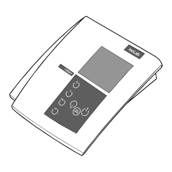
Page 6: Keyboard
Overview Keyboard Measuring instrument ON/OFF Select measuring mode Set up or determine cell constant; select temperature compensation Activate/deactivate AutoRead function Confirm inputs, start AutoRead Increase values, scroll Reduce values, scroll... -
Page 7: Display
Plug-in power supply (option) Caution Only connect measuring cells to the instrument that cannot feed excessive voltages or currents (> SELV and > circuit with current limiter). Almost all commercial measuring cells - especially WTW measuring cells - meet these requirements. - Page 8 Overview...
-
Page 9: Safety
Safety Safety This operating manual contains basic instructions that you must follow during the commissioning, operation and main- tenance of the conductivity meter. Consequently, all respon- sible personnel must read this operating manual before working with the instrument. The operating manual must always be available within the vicinity of the instrument. -
Page 10: Authorized Use
In this event, wait until the temperature of the instrument reaches room tem- perature before putting the instrument back into operation. Caution The instrument is only allowed to be opened by personnel authorized by WTW. - Page 11 Safety Safe operation If safe operation is no longer possible, the instrument must be taken out of service and secured against inadvertent op- eration. Safe operation is no longer possible if: the instrument has been damaged in transport the instrument has been stored under adverse conditions for a lengthy period of time the instrument is visibly damaged the instrument no longer operates as described in this...
- Page 12 Safety...
-
Page 13: Commissioning
Use original plug-in power supplies only (see chapter 7 T ECHNICAL 1 Insert the plug (1) into the socket (2) of the conductiv- ity meter. 2 Connect the original WTW plug-in power supply (3) to an easily accessible mains socket. - Page 14 Commissioning Scope of delivery Laboratory measuring instrument, inoLab Cond Level 1 Operating manual and short manual 4 x type AA Mignon 1.5 V batteries...
-
Page 15: Operation
Operation Operation Switch on the instrument 1 Place the instrument on a flat surface and protect it against intense light and heat. 2 Connect the conductivity measuring cell to the instru- ment. 3 Press the key. The display test appears briefly on the display. The instrument then switches automatically to the previously selected measuring mode. - Page 16 Operation Checking the cell 1 Press the key repeatedly until LF CELL is dis- constant played. 2 Press the key. The previously selected cell con- stant ist displayed, e. g. 0.475 cm 3 To return to the measuring mode: press the when the correct cell constant ist displayed.
-
Page 17: Measuring
Measurements can be performed with and without a temper- ature probe. A connected temperature probe is indicated by TP on the display. If you want to use a WTW conductivity measuring cell with- out a temperature probe, you have to connect it with an adapter (available at WTW). - Page 18 Operation AutoRead AR The AutoRead function (drift control) checks the stability of (Drift control) the measurement signal. The stability has a considerable ef- fect on the reproducibility of the measured values. 1 Call up the required measuring mode by pressing 2 Activate the AutoRead function by pressing The current measured value is frozen (Hold function).
-
Page 19: Conductivity / Specific Resistance
Operation 4.2.1 Conductivity / Specific resistance Note You can display measured values in the units µS/cm (con- ductivity) or MΩ·cm (specific resistance). This setting is de- scribed in Abschnitt 4.5 C ONFIGURATION Thus, you can carry out conductivity measurements or mea- surements of the specific resistance: 1 Perform the preparatory activities according to sec- tion 4.2. -
Page 20: Salinity
Operation 4.2.2 Salinity To measure the salinity, proceed as follows: 1 Perform the preparatory activities according to sec- tion 4.2. 2 Immerse the conductivity measuring cell into the test sample. 3 Press the key repeatedly until Sal appears in the status line. -
Page 21: Tds (Total Dissolved Solids)
Operation 4.2.3 TDS (total dissolved solids) To measure the TDS, proceed as follows: 1 Perform the preparatory activities according to sec- tion 4.2. 2 Immerse the conductivity measuring cell into the test sample. 3 When measuring with an integrated temperature probe continue with step 4. -
Page 22: Determining/Setting Up The Cell Constant [C]
Operation Determining/setting up the cell constant [C] Why determine/set Due to ageing, the cell constant slightly changes. As a re- up the cell con- sult, an inexact measured value is displayed. Calibration de- stant? termines the current value of the cell constant and stores this value in the instrument. - Page 23 Operation 4 Immerse the measuring cell into the 0.01 mol/l KCL control standard. 5 Press the key. – If no temperature probe is connected, enter the current temperature of the solution using and confirm with – If a temperature probe is connected, the AR measurement to determine the cell constant starts.
- Page 24 Operation Note This method of automatically determining the cell constant by calibrating in the 0.01 mol/l KCL control standard can only be used for measuring cells with a cell constant in the range 0.450 ... 0.500 cm or 0.800 ... 1.200 cm Calibration After calibrating, the instrument automatically evaluates the evaluation...
-
Page 25: Setting The Cell Constant Manually
Operation 4.3.2 Setting the cell constant manually Note The cell constant to be set up must either be taken from the operating manual of the measuring cell or is printed on the measuring cell. You can set the the cell constant manually as follows: Setting the fixed cell 1 Press the key repeatedly until CELL appears on... - Page 26 Operation Range 1 Press the key repeatedly until CELL appears on 0.090 ... 0.110 cm the display. 2 Press the key. 3 Press the key repeatedly until a cell constant in the range 0.090 ... 0.110 cm appears. 4 Set the cell constant to be used with e.g.
- Page 27 Operation Range 1 Press the key repeatedly until CELL appears on 0.250 ... 2.500 cm the display. 2 Press the key. 3 Press the repeatedly until until a cell constant in the range 0.250 ... 2.500 cm appears. 4 Set the cell constant to be used with e.g.
-
Page 28: Setting Up The Temperature Compensation Tc
Operation Setting up the temperature compensation TC The calculation of the temperature compensation is based on the preset reference temperature, Tref 20 or Tref 25 (see section 4.5 C ONFIGURATION You can select one of the following temperature compensa- tions: Non-linear temperature compensation "nLF"... - Page 29 Operation Selecting the non- To select the non-linear temperature compensation proceed linear temperature as follows: compensation 1 Press the key repeatedly until LF tc appears on the display. 2 Press the key. 3 Press the key repeatedly until nLF appears on the display.
- Page 30 Operation Selecting the linear To select the linear temperature compensation proceed as temperature follows: compensation 1 Press the key repeatedly until LF tc appears on the display. 2 Press the key. 3 Press the key repeatedly until the adjustable lin- ear temperature coefficient appears on the display.
- Page 31 Operation Switching off the To switch off the temperature compensation proceed as fol- temperature lows: compensation 1 Press the key repeatedly until LF tc appears on the display. 2 Press the key. 3 Press the key repeatedly until the following dis- play appears: 4 The temperature compensation has been switched off.
-
Page 32: Configuration
Operation Configuration You can adapt the conductivity meter to your individual re- quirements. To do this, the following parameters can be changed: Reference temperature 20 °C or 25 °C Conductivity measurement or resistance measurement °C or °F 1 Switch off the instrument. 2 Press and hold down the key. - Page 33 Operation Setting the The reference temperature can either be set to 25 °C reference to 20 °C temperature On delivery, the measuring instrument is set to 25 °C. toggle between t25 and t20 1 With 2 Confirm with The instrument changes to the next setting mode. Conductivity and On delivery, the measuring instrument is set to conductivity resistance...
- Page 34 Operation Setting °C or °F On delivery, the measuring instrument is set to °C. 5 With toggle between °C and °F. 6 Confirm with The instrument changes to the measuring mode.
-
Page 35: Reset
Operation Reset Basic settings The following functions are reset (initialized) to the values they had on delivery: Measuring mode Cell constant 0.475 cm (calibrated) 0.475 cm (set up) Temperature compensation Reference temperature Temperature coefficient of the lin- 2.000 %/K ear temperature compensation TDS factor 1.00 Proceed as follows:... - Page 36 Operation...
-
Page 37: Maintenance, Cleaning, Disposal
Maintenance, cleaning, disposal Maintenance, cleaning, disposal Maintenance The measuring instrument is almost maintenance-free. The only maintenance task is replacing the batteries: 1 Open the battery compartment (1) on the underside of the instrument. 2 Remove the four batteries from the battery compart- ment. -
Page 38: Cleaning
Maintenance, cleaning, disposal Cleaning Occasionally wipe the outside of the measuring instrument with a damp, lint-free cloth. Disinfect the housing with iso- propanol as required. Caution The housing is made of synthetic material (ABS). Thus, avoid contact with acetone or similar detergents that contain solvents. -
Page 39: What To Do If
You would like to Ursache Behebung know which soft- – e.g. question of the WTW – Press the key and ware version is in service department switch on instrument. the instrument The software version... - Page 40 What to do if...
-
Page 41: Technical Data
Technical Data Technical Data Storage tempera- - 25 °C ... + 65 °C Ambient ture temperature Operating temper- 0 °C ... + 55 °C ature Allowable relative Annual mean: < 75 % humidity 30 days/year: 95 % Other days: 85 % [µS/cm] 0.000 ... - Page 42 0 °C ... 35 °C according to EN 27 888; ± 0.5 % 35 °C ... 50 °C extended nLF function according to WTW measurements Linear compensation Accuracy Test sample temperature ± 0.5 % 10 °C ... 75 °C (the accuracy percentage always refers to the measured value!) Range 0.0 ...
- Page 43 Technical Data Cell constant, C [cm 0.010 to be set 0.090 ... 0.110 0.250 ... 2.500 Cell constant, C [cm 0.450 ... 0.500 calibrated 0.800 ... 1.200 Reference tempera- [°C] ture, selectable Temperature input Manual [°C] - 5 ... +100 Dimensions and Length [mm] weight...
- Page 44 Technical Data Batteries 4 x 1.5 V AA type alkaline manga- Energy supply nese batteries Runtime Approx. 3000 operating hours Mains power supply Connection max. overvoltage cate- (option) gory II (valid for all plug-in power supply units): Plug-in power supply (Euro plug): FRIWO FW1199, 11.7864 Friwo Part.
-
Page 45: Lists
Lists Lists This chapter provides additional information and orientation aids. Abbreviations The list of abbreviations explains abbreviations that appear on the display or when dealing with the instrument. Specialist terms The glossary briefly explains the meaning of the specialist terms. However, terms that should already be familiar to the target group are not described here. - Page 46 Lists Abbreviations Conductivity value AutoRead (drift control) ARng Automatic range switching Measuring instrument measures with high- est resolution Cell constant cm Calibration CELL Cell constant Error message (see chapter 6 W HAT TO DO ...) Initialization Resets individual basic functions to the status they had on delivery Linear temperature compensation LoBat...
- Page 47 Lists Glossary AutoRead Monitors the electrode drift and releases the measured val- ue only after the stability criterion has been reached. In this way, this procedure ensures the highest degree of precision and reproducibility. Calibration The cell constant is determined through calibration. To do so, the conductivity measuring cell is immersed into a series of aqueous salt solutions with exactly known electric con- ductivity.
- Page 48 Lists Resistance All substances (solids, liquids, or gases) with mobile charge carriers like for example electrons or ions have a finite ohmic resistance, which means they have an electric conductance that can be measured or an electric conducitivtiy. Salinity The salinity is a sum parameter especially for seawater; it gives the salt content of seawater.
- Page 49 Lists Index authorized use operation AutoRead operational safety basic settings parameters, reset battery compartment place of the instrument plug-in power supply calibration calibration evaluation reference temperature cell constant replacing the batteries 16, 22 cleaning reset Conductivity resistance measurement conductivity measurement configuration safety safety precautions...
- Page 50 Lists...
-
Page 51: Appendix
Appendix Appendix... - Page 52 Note If you need further informationen or application notes you can ask for: Application reports Primers Safety data sheets. You can find information on available literature in the WTW , or via catalog, L ABORATORY AND IELD NSTRUMENTATION the Internet.
Need help?
Do you have a question about the inoLab Cond Level 1 and is the answer not in the manual?
Questions and answers