Table of Contents
Advertisement
Quick Links
Advertisement
Table of Contents
Troubleshooting

Related Manuals for Oracle X7-8


Summary of Contents for Oracle X7-8
- Page 1 Oracle Server X7-8 Service Manual ® Part No: E71936-04 April 2018...
- Page 3 Oracle. Oracle Corporation and its affiliates will not be responsible for any loss, costs, or damages incurred due to your access to or use of third-party content, products, or services, except as set forth in an applicable agreement between you and Oracle.
- Page 4 Oracle Corporation et ses affiliés déclinent toute responsabilité ou garantie expresse quant aux contenus, produits ou services émanant de tiers, sauf mention contraire stipulée dans un contrat entre vous et Oracle. En aucun cas, Oracle Corporation et ses affiliés ne sauraient être tenus pour responsables des pertes subies, des coûts occasionnés ou des dommages causés par l'accès à...
-
Page 5: Table Of Contents
Contents Using This Documentation ................ 13 Product Documentation Library ............... 13 Feedback ...................... 13 About the Oracle Server X7-8 ................ 15 Product Description .................. 15 About Controls and Connectors ............... 17 Front Panel Components ................. 17 Back Panel Components ................. 19 Replaceable Components ................ 22 Illustrated Parts Breakdown .............. 22 Component Serviceability Requirements ............ 24 Customer-Replaceable Units .............. - Page 6 Troubleshooting and Diagnostics .............. 45 Detecting and Managing Server Faults .............. 45 Troubleshooting Server Hardware Faults ........... 46 Managing Server Hardware Faults Using the Oracle ILOM Fault Management Shell .................... 51 ▼ Clear Hardware Fault Messages (Oracle ILOM) ........ 51 Troubleshooting Using a CMOD Fault Remind Test Circuit ...... 53 Troubleshooting System Cooling Issues ............. 53...
- Page 7 ▼ Prepare the Server for Warm Service (Oracle ILOM Web Interface) .. 106 ▼ Prepare the Server for Cold Service (Oracle ILOM CLI) ...... 107 ▼ Prepare the Server for Cold Service (Oracle ILOM Web Interface) ... 109 Powering Down the Server ................ 110 ▼ Power Off the Server Gracefully (Oracle ILOM CLI) ...... 111 ▼...
- Page 8 Servicing DIMMs (CRU) .............. 182 ▼ Upgrade the Server From Four to Eight CMODs (FRU) ...... 195 Servicing System Module (SMOD) Components (FRU) ........ 198 SMOD Population Rules ............... 198 ▼ Remove an SMOD ................. 199 ▼ Install an SMOD ................ 201 Oracle Server X7-8 Service Manual • April 2018...
- Page 9 Single 4-Socket (1x4) Server .............. 248 Dual 4-Socket (2x4) Servers .............. 251 Single 8-Socket (1x8) Server .............. 254 Oracle X7-8 CPU Packages ................ 257 ▼ Configure Single 4-Socket Server to Dual 4-Socket Servers (FRU) .... 258 ▼ Configure Dual 4-Socket Server to Single 8-Socket Server (CRU) .... 261 ▼...
- Page 10 BIOS IO Menu Selections ................ 326 BIOS IO Menu PCI Subsystem Settings Options ........ 327 BIOS IO Menu IO Virtualization Options .......... 328 BIOS IO Menu IOAT Configuration Options .......... 329 BIOS IO Menu Internal Devices Options .......... 329 Oracle Server X7-8 Service Manual • April 2018...
- Page 11 BIOS Boot Menu Selections ................ 330 BIOS Save and Exit Menu Selections .............. 332 Monitoring and Identifying Server Components .......... 335 Monitoring Component Health and Faults Using Oracle ILOM ...... 335 Monitoring System Components .............. 336 System Components (FRUs) Network Access Control (NAC) Names .... 337 System Indicators Network Access Control (NAC) Names ........ 338 System Sensors Network Access Control (NAC) Names ........
- Page 12 Oracle Server X7-8 Service Manual • April 2018...
-
Page 13: Using This Documentation
Using This Documentation Overview – Describes how to troubleshoot and maintain the Oracle Server X7-8. ■ Audience – Technicians, system administrators, authorized service providers, and trained ■ hardware service personnel who have been instructed on the hazards within the equipment and are qualified to remove and replace hardware. - Page 14 Oracle Server X7-8 Service Manual • April 2018...
-
Page 15: About The Oracle Server X7-8
Server X7-8 Installation Guide. Product Description Oracle Server X7-8 is an enterprise-class 5 rack unit (5U) server. You can configure the server as one 4-socket server, two independent 4-socket servers, or one 8-socket server. The system supports the following components. - Page 16 ■ Oracle Integrated Lights Out Management (ILOM). Refer to the Oracle ILOM 4.0 Documentation Library at https://www.oracle.com/goto/ilom/docs ■ Oracle Hardware Management Pack, available with the Oracle Solaris OS or as a standalone product with other OS. Refer to the support matrix for specific information https://www.
-
Page 17: About Controls And Connectors
About Controls and Connectors Feature System Component ■ Oracle Enterprise Manager Ops Center, available software to manage multiple systems in a data center. Refer to the product information page at: http://www.oracle.com/technetwork/oem/ ops-center/index.html Operating Systems and ■ Oracle Solaris 11.3 SRU 23 Virtualization Software ■... - Page 18 Chassis SMOD0 Rear Fault-Service Required LED: amber CMOD0-3 Fault-Service Required LEDs 0, 1, 2, 3: amber ■ SMOD1 System B controls and indicators: Locate Button/LED: white Fault-Service Required LED: amber System OK indicator: green Oracle Server X7-8 Service Manual • April 2018...
-
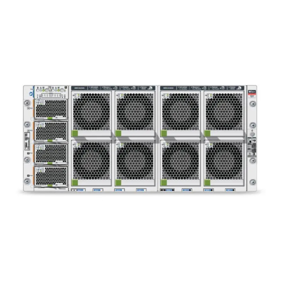
Page 19: Back Panel Components
System A: CMODs 0-3; System B: CMODs 4-7. 4-socket mode: CMODs 0-3. 8-socket mode: CMODs 0-7 For component serviceability, locations, and designations, see “Replaceable Components” on page Back Panel Components The following figure shows the Oracle Server X7-8 chassis back panel components. About the Oracle Server X7-8... - Page 20 (FRU)” on page 198 SMOD1 System B NET MGT “System Module (SMOD) Overview” on page 32 Oracle ILOM (SP) network management 10/100/1000 GbE Network Ethernet port. “Networking Subsystem” on page 88 “Servicing System Module (SMOD) Components (FRU)” on page 198 SMOD1 System B SER MGT “System Module (SMOD)
- Page 21 “System Module (SMOD) Overview” on page 32 Serial management port labled SER MGT uses an RJ-45 cable and terminal (or emulator) to provide access to the Oracle ILOM command-line interface “Servicing System Module (SMOD) Components (CLI). (FRU)” on page 198 SMOD0 System A USB “System Module (SMOD)
-
Page 22: Replaceable Components
SMOD0 System A: AC 3 (Top), AC 2 ; SMOD1 System B: AC 1, AC 0 “AC Power Block Inlet Indicators” on page 69 (bottom) The server does not provide video display ports on the SMODs. Use Oracle ILOM Note - RKVMS to display video. - Page 23 “Servicing CPU Module (CMOD) Components (FRU)” on page 159 Memory, front panel accessible “Servicing CPU Module (CMOD) Components (FRU)” on page 159 Fan frame (2), front panel accessible “Servicing Fan Modules (CRU) and Fan Frames (CRU)” on page 129 About the Oracle Server X7-8...
-
Page 24: Component Serviceability Requirements
A CRU or FRU designation determines who is qualified to service a component. Customer-replaceable units (CRUs) can be serviced by customers. ■ Field-replaceable units (FRUs) must be serviced by qualified Oracle Service personnel. ■ Customer-Replaceable Units The following table lists the customer-replaceable units (CRUs) in the server and directs you to the replacement instructions. -
Page 25: Field-Replaceable Units
(CRU)” on page 146 Optional add-in cards that can expand the functionality of the server. The Oracle Storage 12 Gb/s SAS PCIe RAID HBA card Note - is a field replaceable unit (FRU) and should only be serviced by authorized Oracle Service personnel. -
Page 26: Cpu Module (Cmod) Overview
Oracle Storage Cold-serviceable “Servicing the Host Bus Adapter (HBA) Card 12 Gb SAS (FRU)” on page 204 Located in SMODs, the Oracle Storage 12Gb SAS PCIe RAID PCIe RAID HBA, Internal 16-Port manages SAS storage drives. HBA, Internal card Front indicator Cold-serviceable “Servicing the Front Indicator Module... -
Page 27: Cmod Components
Fault Remind Test Circuit, which helps you locate failed DIMMs and verify a failed CPU ■ Fault Remind button ■ 12 DIMM slot fault indicators ■ 1 CPU fault indicator ■ The following illustration shows CMOD component locations. About the Oracle Server X7-8... -
Page 28: Cmod Processor
Eight CPU modules installed in slots 0 through 7 ■ 24 cores per-socket (8-socket = 192 total, 4-socket = 96 total) ■ The Processor Heatsink Module (PHM) is a three-part module that is installed above the socket assembly. Oracle Server X7-8 Service Manual • April 2018... -
Page 29: Cmod Memory
■ The maximum system memory with DDR4-2666 32 GB RDIMMs is: Four CMODs: 1.5 TB with 48 installed x 64 GB LRDIMMs ■ Eight CMODs: 3 TB with 96 installed x 64 GB LRDIMMs ■ About the Oracle Server X7-8... - Page 30 Channel A, Slot 1, DIMM 7 Channel B, Slot 0, DIMM 8 Channel B, Slot 1, DIMM 9 Channel C, Slot 0, DIMM 10 Channel C, Slot 1, DIMM 11 “Servicing DIMMs (CRU)” on page 182. Oracle Server X7-8 Service Manual • April 2018...
-
Page 31: Cmod And Fan Module Power
CMOD 6 FM6 and FM7 CMOD1, CMOD3, CMOD5, and CMOD7 in chassis slots 1, 3, 5, and 7 do not supply fan module power. “Servicing Fan Modules (CRU) and Fan Frames (CRU)” on page 129. About the Oracle Server X7-8... -
Page 32: System Module (Smod) Overview
One Internal PCIe slot for RAID storage HBA connectivity to drive bays. ■ This PCIe slot is populated by one PCIe Gen3 x8 HBA per SMOD (Oracle Storage 12Gb SAS PCIe RAID HBA, Internal 16-Port). Four ports in the card are used for SAS connectivity. - Page 33 SMOD0 and SMOD1 removal and installation levers with green lock release tabs. Call Description SMOD1 ejector levers (2) SMOD1 installed in chassis SMOD0 ejector levers (2) SMOD0 installed in chassis Related Information “System Module (SMOD) Indicators” on page 63 ■ About the Oracle Server X7-8...
-
Page 34: Smod Components
The following illustration shows an SMOD (system module) and associated components, including an Oracle Storage 12Gb SAS PCIe RAID HBA, Internal 16-Port card installed below the SMOD, one SAS cable that connects the HBA card to the server storage backplane, and an ESM extension cable that connects the energy storage module to the HBA card. -
Page 35: Smod Motherboard
System Module (SMOD) Overview Call Description SAS host bus adaptor (HBA): Oracle Storage 12Gb SAS PCIe RAID HBA, Internal 16-Port Energy storage module (ESM) Cable from HBA to ESM SMOD motherboard Storage drive SMOD midplane connectors (4) Four server storage drives 0-3 (HDD/SSD), back panel accessible... -
Page 36: Server Storage Drives
Energy storage module (ESM) for the server storage HBA ■ The ESM provides backup power for the Oracle Storage 12Gb SAS PCIe RAID HBA, Internal 16-Port card. The ESM is located in a holder in the top center of the SMOD. A cable connects the HBA to to the ESM. -
Page 37: Server Chassis Overview
“Chassis Features” on page 38 ■ “Chassis Internal Components” on page 39 ■ “Chassis Front Panel Components” on page 40 ■ “Chassis Back Panel Components” on page 41 ■ “Switches and Buttons Reference” on page 42 ■ About the Oracle Server X7-8... -
Page 38: Chassis Features
Four front-loaded hot-swap power supply units (PSUs) in a two per SMOD 1+1 ■ configuration. Expandable IO: Eight 16-lane and eight 8-lane PCIe Gen3 chassis slots. One x8 PCIe Gen 3 ■ HBA SMOD slot. Oracle Server X7-8 Service Manual • April 2018... -
Page 39: Chassis Internal Components
The following figure shows the chassis internal components. The chassis internal components are described in the following table. Call Component Description Links Top Cover This component is part of the chassis and is non- “Remove the Midplane replaceable. Assembly” on page 231. About the Oracle Server X7-8... -
Page 40: Chassis Front Panel Components
The following figure shows the server chassis front panel accessible replaceable components. Call Component Links Front indicator module (FIM) “Servicing the Front Indicator Module (FRU)” on page 226 “Front Indicator Module (FIM) Panel” on page 58 Oracle Server X7-8 Service Manual • April 2018... -
Page 41: Chassis Back Panel Components
Left facing back of chassis: SMOD1 HDD/SSD “Storage Drive Locations and slots 0 through 3: Numbering” on page 124 Right facing back of chassis: SMOD0 HDD/SSD “Storage Drive slots 0 through 3: Indicators” on page 67 Top row : 3, 1 About the Oracle Server X7-8... -
Page 42: Switches And Buttons Reference
Press the buttons on the server front panel FIM to manage the “Managing the Locate Button/ Locate Buttons/ SMOD0 or SMOD1 Locate Button/LED indicator locally. To LED” on page 119 LEDs deactivate (or activate) the Locate Button/LED, press and release the button. Oracle Server X7-8 Service Manual • April 2018... - Page 43 (CRU)” on page 146 (attention) buttons After installing a DPCC that contains a PCIe card, press the buttons “Dual PCIe Card Carrier (DPCC) (two on each DPCC) again. Indicators” on page 68 “Back Panel Components” on page 19 About the Oracle Server X7-8...
- Page 44 Oracle Server X7-8 Service Manual • April 2018...
-
Page 45: Troubleshooting And Diagnostics
“Getting Help” on page 94 ■ “Auto Service Requests” on page 95 ■ For more information about server troubleshooting and diagnostics, refer to the Oracle x86 Servers Diagnostics and Troubleshooting Guide for Servers With Oracle ILOM 4.0.x at https: //www.oracle.com/goto/x86admindiag/docs. -
Page 46: Troubleshooting Server Hardware Faults
When a server hardware fault event occurs, the system lights the Fault-Service Required LED and captures the event in the Oracle ILOM event log. If you set up notifications through Oracle ILOM, you also receive an alert through the notification method you chose. When you become aware of a hardware fault, address it immediately. - Page 47 Oracle ILOM, depending on the component requirements. “Clear Hardware Fault Messages (Oracle ILOM)” on page Identify Hardware Faults (Oracle ILOM) Use this procedure to troubleshoot hardware faults with the Oracle ILOM web interface and, if necessary, prepare the server for service. Troubleshooting and Diagnostics...
- Page 48 This example procedure provides one method to troubleshoot hardware faults using Oracle ILOM web and CLI interfaces. However, the procedure can be performed using only the Oracle ILOM CLI interface. For more information about Oracle ILOM interfaces, refer to the Oracle ILOM documentation.
- Page 49 Identify Hardware Faults (Oracle ILOM) The Status table lists components that require service. In the above example, the Status table shows that the Memory subsystem requires service. This indicates that a hardware component within the subsystem is in a fault state.
- Page 50 Before going to the server, review the Oracle Server X7-8 Product Notes information related to the issue or the component. For up-to-date information about the server, including hardware-related issues, refer to Oracle Server X7-8 Product Notes at: https://www.oracle.com/goto/x7-8/docs To prepare the server for service, see “Preparing for Service”...
-
Page 51: Managing Server Hardware Faults Using The Oracle Ilom Fault Management
Managing Server Hardware Faults Using the Oracle ILOM Fault Management Shell The Oracle ILOM Fault Management Shell enables you to view and manage fault activity on a managed servers and other types of devices. For more information about how to use the Oracle ILOM Fault Management Shell, see the Oracle ILOM User's Guide for System Monitoring and Diagnostics Firmware Release 4.0.x in... - Page 52 Where ipaddress is the IP address of the server SP. For more information, see “Using Oracle ILOM” in Oracle Server X7-8 Installation Guide. The Oracle ILOM CLI prompt appears: -> To access fmadm, type: ->...
-
Page 53: Troubleshooting Using A Cmod Fault Remind Test Circuit
Clear Hardware Fault Messages (Oracle ILOM) Type fmadm to clear the fault. Select acquit, repair, replaced, or repaired. Close the Oracle ILOM session. Troubleshooting Using a CMOD Fault Remind Test Circuit The CMODs have an internal test circuit with indicators that you can use to locate failed DIMMs and verify a failed CPU after removing the CMOD from the server. - Page 54 For example, power supplies serve a dual function; they provide both power and airflow. If one power supply fails, the other functioning power supply can maintain both the power and the cooling subsystems. Oracle Server X7-8 Service Manual • April 2018...
-
Page 55: Troubleshooting Power Issues
Clear Hardware Fault Messages (Oracle ILOM) Troubleshooting Power Issues If your server does not power on, the cause of the problem might be server AC power connections or power supplies (PS0-3). In maximally configured systems, it is possible that the worst-case power consumption of the system could exceed the capacity of a single PS. -
Page 56: Troubleshooting Using Diagnostic Tools
Diagnostic tools range in complexity from a comprehensive validation test suite (Oracle VTS) to a chronological event log (Oracle ILOM System Log). Tools include standalone software packages, firmware-based tests, and hardware-based LED status indicators. -
Page 57: Troubleshooting Using Status Indicators
Troubleshooting Using Status Indicators Diagnostic Tool Diagnostic Type Function Availability and Access Links View Oracle ILOM System Log. Oracle Hardware View System Log. Monitor Access either in Standby power https://www.oracle. Management Pack environmental conditions or Main power mode. OS com/goto/ohmp/docs and component functionality independent. -
Page 58: Front Indicator Module (Fim) Panel
8-socket: The FIM provides controls and indicators for System A (SMOD0) and System B ■ CMODs 4-7. Other System B (SMOD1) buttons and indicators are not operational. The following figure shows FIM buttons and indicators. Oracle Server X7-8 Service Manual • April 2018... - Page 59 Indicates the location of the SMOD System A in the server: SMOD0 System A) ■ Off – Server is operating normally. ■ Fast blink – Use Oracle ILOM to activate this LED to enable you to locate a system quickly and easily. White On when SMOD0 System A Locate Button on the server is pressed.
- Page 60 Indicates the SMOD1 System B location in the server when pressed. (SMOD1 System B) ■ Off – Server is operating normally, ■ Fast blink – Use Oracle ILOM to activate this LED to enable you to locate a system quicklly and easily. White “Managing the Locate Button/LED”...
-
Page 61: Fan Module (Fm) Indicators
246. SP OK (SMOD1 System B) Indicates when SMOD1 System B SP service processor (SP) is booting: ■ Flashing – SP is booting. ■ Steady On – Oracle ILOM is operational. Green “System Module (SMOD) Indicators” on page 63 “Troubleshooting Using Status Indicators”... -
Page 62: Power Supply (Ps) Indicators
Each power supply (PS) has three indicators arranged in a single row from left to right. Power supplies for System A are PS2 and PS3. Power supplies for System B are PS0 and PS1. Oracle Server X7-8 Service Manual • April 2018... -
Page 63: System Module (Smod) Indicators
■ Off – Power supply is operating normally, Required ■ Fast blink – Use Oracle ILOM to activate this LED to enable you to locate a power supply quickly and easily. ■ Steady On –Lights steady on when the power supply is in a fault state. - Page 64 Oracle ILOM tasks. ■ Off – Server is operating normally, White ■ Fast blink – Use Oracle ILOM to activate this LED to enable you to locate a system quicklly and easily. “Managing the Locate Button/LED” on page 119.
- Page 65 SMOD System OK Indicates the operational state of the SMOD: ■ Off – AC power is not present or the Oracle ILOM boot is not complete. ■ Flashing – SMOD is booting. ■ Steady On – OS has booted, power is on, and chassis SMOD is running.
- Page 66 (GbE) RJ-45 NET1 port is active. Indicates a live network. Top right ■ Off– No activity. No link. Not operational. Bi-colored: ■ FLASHING – Packet activity. Blinks with network traffic. Amber/ Green Oracle Server X7-8 Service Manual • April 2018...
-
Page 67: Storage Drive Indicators
The server does not provide video ports on the SMODs. Video display is only available Note - using the Oracle ILOM Remote Console Plus interface. Storage Drive Indicators Storage drives are installed in carriers. Each storage drive carrier has three indicators arranged in a single stacked row and from bottom to top. -
Page 68: Dual Pcie Card Carrier (Dpcc) Indicators
OK/Activity LED Indicates the operational state of the storage drive: ■ Off – AC power is not present or the Oracle ILOM boot is not complete. ■ Flashing – Blinks to show storage drive activity. Storage drive indicators blink rates vary by activity. See “Status Indicator Blink Rates”... -
Page 69: Ac Power Block Inlet Indicators
Amber DPCC Locate LED: ■ Off – DPCC is operating normally. ■ Fast blink – Use Oracle ILOM to activate this LED to enable you to locate a DPCC quickly and easily. DPCC OK indicator Indicates the operational state of DPCC: ■... -
Page 70: About Controls And Indicators
Do not attach power cables to the power supplies until you finish connecting the data cables to the server. The server goes into Standby power mode, and the Oracle ILOM service processor initializes when the AC power cables are connected to the power source. System messages might be lost after 60 seconds if the server is not connected to a terminal, PC, or workstation. - Page 71 Troubleshooting Using Status Indicators For the error state scenarios described below, the OK indicator state depends on presence Note - of redundant components and the severity of the fault. Server Boot Process and Normal Operating State Indicators A normal server boot process involves System A (SMOD0) or System B (SMOD1) service processor SP OK indicator and System OK indicator.
- Page 72 LED, press and release the Locate button. When the Locate Button/LED is on, the LED blinks at the fast blink rate. You can turn the Locate Button/LED off remotely from Oracle ILOM, or by pressing a Locate button on the chassis. The buttons on the server front and back allow you to manage System A (SMOD0) and System B (SMOD1) Locate Buttons/LED indicators locally.
- Page 73 Troubleshooting Using Status Indicators Call System Activity System A ■ Single 4 socket: The FIM Locate Button/LED indicator provides controls and indicators for System A SMOD0 (SMOD0) only. ■ Dual 4 socket: The FIM Locate Button/LED indicator provides separate controls and indicators for System A (SMOD0) and System B (SMOD1).
- Page 74 For a server with an SP (service processor) fault, the server amber Fault-Service Required LEDs (front and back) are steady on. The front and back System OK indicators and the SP OK indicator are off. Oracle Server X7-8 Service Manual • April 2018...
- Page 75 Button Icon Description Non-maskable Interrupt (NMI) Do not press. This button is used by Oracle Service personnel only and button (recessed) SMOD0 requires a stylus. SP Reset button (recessed) SMOD0 Performs an immediate System A (SMOD0) SP reboot and requires a stylus.
-
Page 76: Status Indicator Blink Rates
For the steady off state, an indicator is continually off (not lit) and does not blink. This indicates that a system is not operational, for example, no AC power (unlit green OK indicator) or a subsystem not in a fault state (unlit amber Fault-Service Required LED). Oracle Server X7-8 Service Manual • April 2018... - Page 77 Troubleshooting Using Status Indicators Slow Blink Rate For the slow blink rate, the indicator (typically green) repeatedly lights for half a second during a one second interval (1 Hz) and turns off for half a second. The slow blink rate indicates an on-going activity, for example, device rebuilding, booting, or in transition from one mode to another.
- Page 78 The insertion blink is three successive blinks of a hot-swap component's primary status indicator, for example, the green OK indicator. The insertion blink occurs immediately after three successive unison blinks (see “Slow Unison Blink Rate” on page 78) of all the component indicators. Oracle Server X7-8 Service Manual • April 2018...
- Page 79 Troubleshooting Using Status Indicators Unison Steady On For the unison steady on, all indicators are simultaneously steady on (see “Steady On” on page 76. This occurs during the front panel lamp test (see “Front Panel Lamp Test” on page 75). This is the only time that the Locate Button/LED indicator is steady on. Alternating (Invalid FRU) Blink Rate The alternating (invalid FRU) blink rate is a repeating sequence of lit green and amber indicators at 1 Hz.
-
Page 80: Troubleshooting Server Subsystems
“Replaceable Components” on page Processor Subsystem Use the Oracle Integrated Lights Out Manager (ILOM) Processors page to view the health of the CPUs installed on the CMODs. The server processor subsystem consists of the following: Oracle Server X7-8 Service Manual • April 2018... -
Page 81: Memory Subsystem
All 8 fan modules must be installed. Fans FM0-7 are active. ■ Memory Subsystem Use the Oracle Integrated Lights Out Manager (ILOM) Memory page to view the health of the DIMMs installed on your system. The server memory subsystem consists of the following: Memory: Up to 48 (4-socket) or up to 96 (8-socket) DDR4 RDIMM slots. -
Page 82: Power Subsystem
■ Power Subsystem Use the Oracle Integrated Lights Out Manager (ILOM) Power page to view the overall health and power consumption of the power supplies installed in your system. Review the Power Supplies table for details about the health and location of individual power supplies. - Page 83 Standby power mode. Once the SP boots into Standby power, Main power is initiated by pressing and releasing the chassis front panel On/Standby button or by powering on the server remotely from Oracle ILOM. For more information about power control, see “Power Control, Shutdown, and Reset...
-
Page 84: Cooling Subsystem
AC power source. Cooling Subsystem Use the Oracle Integrated Lights Out Manager (ILOM) Cooling page to view the health and number of fans installed in your system. Additionally, you can view the server inlet and exhaust temperatures. Review the Fans table for details about the health and location of individual fans. - Page 85 Troubleshooting Server Subsystems All DPCCs are installed regardless of whether they contain a card or not. ■ Both fan frames are populated with fan modules. ■ Each fan frame and fan module is populated. ■ All CMOD processors have a heatsink. ■...
- Page 86 ■ The following table lists the CMODs and the fan modules to which they supply power. CMOD Fan Modules Powered CMOD0 FM0 and FM1 CMOD2 FM2 and FM3 CMOD4 FM4 and FM5 Oracle Server X7-8 Service Manual • April 2018...
-
Page 87: Storage Subsystem
Frames (CRU)” on page 129. Storage Subsystem Use the Oracle Integrated Lights Out Manager (ILOM) Storage page to view tables listing health and inventory information for storage devices detected on your server. The server storage subsystem consists of the following: Storage Drives: 8 hot-swappable SAS3 HDD or SSD SFF drives, four per SMOD. -
Page 88: Networking Subsystem
Troubleshooting Server Subsystems Networking Subsystem Use the Oracle Integrated Lights Out Manager (ILOM) Networking page to view networking information, including the status of Ethernet Controllers and Infiniband Controllers. The server networking subsystem consists of the following: Ethernet Controllers for network ports: ■... -
Page 89: Pci Devices Subsystem
Note - PCI Devices Subsystem Use the Oracle Integrated Lights Out Manager (ILOM) PCI Devices page to view inventory properties for the PCIe add-in cards and the built-in devices that are detected on your server. To view the inventory properties for the devices shown on the PCI Devices page, follow these steps: 1. -
Page 90: Attaching Devices To The Server
For port and connector information, see “Back Panel Connector Locations” on page 91 “Back Panel Components” on page Connect four Ethernet cables to the Gigabit Ethernet (NET) connectors as needed for OS support. Oracle Server X7-8 Service Manual • April 2018... -
Page 91: Back Panel Connector Locations
Attach Devices to the Server To connect to Oracle ILOM over the network, connect an Ethernet cable to the Ethernet port labeled NET MGT. To access the Oracle ILOM command-line interface (CLI) locally using the management port, connect a serial null modem cable to the RJ-45 serial port labeled SER MGT. -
Page 92: Configuring Serial Port And Network Port Sharing
200-240 VAC only. Configuring Serial Port and Network Port Sharing By default, the SER MGT port connects to the Oracle ILOM CLI. You can assign serial port output using either the Oracle ILOM web interface or the command-line interface (CLI). For instructions, see the following sections: “Assign Serial Port Output (Oracle ILOM CLI)”... - Page 93 Assign Serial Port Output (Oracle ILOM CLI) Assign Serial Port Output (Oracle ILOM CLI) Log in to the System A or System B SP Oracle ILOM CLI. Log in as a user with root or administrator privileges. For example: ipaddress ssh root@ Where ipaddress is the IP address of the server SP.
-
Page 94: Ethernet Device Naming
“Locating the Chassis Serial Number” on page 95 ■ Contacting Support If the troubleshooting procedures in this chapter fail to solve your problem, use the following table to collect information that you might need to communicate to support personnel. Oracle Server X7-8 Service Manual • April 2018... -
Page 95: Locating The Chassis Serial Number
From the web interface, view the serial number on the System Information screen. ■ Auto Service Requests Oracle Auto Service Requests (ASR) is a feature available to customers having Oracle Premier Support and is provided to those customers at no additional cost. Oracle ASR is the fastest Troubleshooting and Diagnostics... -
Page 96: Oracle Server X7-8 Service Manual • April
Auto Service Requests way to restore system availability if a hardware fault occurs. Oracle ASR software is secure and customer installable, with the software and documentation downloadable from My Oracle Support at https://support.oracle.com. When you log in to My Oracle Support, refer to the "Oracle Auto Service Request"... -
Page 97: Preparing For Service
■ “Prepare the Server for Hot Service (Oracle ILOM CLI)” on page 102 ■ “Prepare the Server for Hot Service (Oracle ILOM Web Interface)” on page 103 ■ “Prepare the Server for Warm Service (Oracle ILOM CLI)” on page 104 ■... -
Page 98: Using An Antistatic Mat
It warns you to not insert your hands or any object into the space left vacant by the removal of the fan module. Fan modules are hot-swap components. Removing a fan module Oracle Server X7-8 Service Manual • April 2018... -
Page 99: Fru Key Identity Properties (Kip) Automated Update
■ When a server FRU that contains the KIP is removed and a replacement component is installed, the KIP of the replacement component is programmed by Oracle ILOM to contain the same KIP as the other two components. Only one of the quorum members can be replaced at a time. Automated updates can only be completed when two of the three quorum members contain matching key identity properties. -
Page 100: Required Tools And Equipment
“Prepare the Server for Hot Service (Oracle ILOM CLI)” on page 102 ■ “Prepare the Server for Hot Service (Oracle ILOM Web Interface)” on page 103 ■ “Prepare the Server for Warm Service (Oracle ILOM CLI)” on page 104 ■... -
Page 101: Serviceability Overview
Dual PCIe Card Carriers (DPCCs), see “Servicing PCIe Cards and Carriers ■ (CRU)” on page 146 “Prepare the Server for Hot Service (Oracle ILOM CLI)” on page 102 “Prepare the Server for Hot Service (Oracle ILOM Web Interface)” on page 103. -
Page 102: Prepare The Server For Hot Service (Oracle Ilom Cli)
“Prepare the Server for Cold Service (Oracle ILOM Web Interface)” on page 109. The steps in these remote procedures use the Oracle ILOM CLI interface or web interface. For more information, refer to the Oracle ILOM 4.0 documentation at: https://www.oracle.com/ goto/ilom/docs. -
Page 103: Prepare The Server For Hot Service (Oracle Ilom Web Interface)
Prepare the Server for Hot Service (Oracle ILOM Web Interface) Main power mode. For more information about component serviceability, see “Component Serviceability Requirements” on page Log in to the SP Oracle ILOM CLI. Log in as a user with root or administrator privileges. For example, open an SSH session, and at... -
Page 104: Prepare The Server For Warm Service (Oracle Ilom Cli)
Serviceability Requirements” on page Log in to the service processor Oracle ILOM web interface. Direct a web browser to Oracle ILOM using the IP address of the server SP. Log in as a user with root or administrator privileges. See “Accessing Oracle ILOM”... - Page 105 Prepare the Server for Warm Service (Oracle ILOM CLI) and their subcomponents without removing the power cords. Oracle ILOM remains available in warm service mode. For more information about component serviceability, see “Component Serviceability Requirements” on page Loss of service or component damage. Do not replace any components except for Caution - CMODs and internal CMOD subcomponents while the server is in warm service mode.
-
Page 106: Prepare The Server For Warm Service (Oracle Ilom Web Interface)
This procedure is performed locally and requires physical access to the server front panel. Log in to the service processor Oracle ILOM web interface. Direct a web browser to Oracle ILOM using the IP address of the server SP. Log in as a user with root or administrator privileges. See “Accessing Oracle ILOM”... -
Page 107: Prepare The Server For Cold Service (Oracle Ilom Cli)
Prepare the Server for Cold Service (Oracle ILOM CLI) In the Actions section of the Summary Information page, verify that the Power State is ON. If the Power State status shows off, the server is already powered off. Power off the server. In the Actions section of the Summary Information page, click the Power State Turn Off button. - Page 108 Prepare the Server for Cold Service (Oracle ILOM CLI) server is completely powered off and AC cords have been removed from the back panel AC power block. For more information about component serviceability, see “Component Serviceability Requirements” on page This procedure is performed locally and requires physical access to the server front and back panels.
-
Page 109: Prepare The Server For Cold Service (Oracle Ilom Web Interface)
Log in to the System A or System B service processor Oracle ILOM web interface using an Administrator account. Direct a web browser to Oracle ILOM using the IP address of the server SP. Log in as a user with root or administrator privileges. See “Accessing Oracle ILOM”... -
Page 110: Powering Down The Server
“Power Off the Server Gracefully (Power Button)” on page 113 If the server is not responding, or you must ■ “Power Off the Server for Immediate Shutdown (Oracle ILOM shut down the server quickly, perform an CLI)” on page 114 immediate shutdown. -
Page 111: Power Off The Server Gracefully (Oracle Ilom Cli)
At the Oracle ILOM prompt, shut down the operating system. Type: -> stop /System If the system is running the Oracle Solaris OS, refer to the Oracle Solaris system administration documentation for additional information. Disconnect the power and cables from the server. -
Page 112: Power Off The Server Gracefully (Oracle Ilom Web Interface)
Log in to the System A or System B service processor Oracle ILOM web interface using an Administrator account. Direct a web browser to Oracle ILOM using the IP address of the server SP. Log in as a user with root or administrator privileges. See “Accessing Oracle ILOM”... -
Page 113: Power Off The Server Gracefully (Power Button)
Disconnect the power cords and data cables from the server. “Remove Power” on page 117. When you power off the server using Oracle ILOM, the server enters Standby power Caution - mode. Power is still directed to the service processor remote management subsystem and power supply fans. -
Page 114: Power Off The Server For Immediate Shutdown (Oracle Ilom Cli)
Disconnect the power and data cables from the server. “Remove Power” on page 117. When you power off the server using Oracle ILOM, the server enters Standby power Caution - mode. Power is still directed to the service processor remote management subsystem and power supply fans. -
Page 115: Power Off The Server For Immediate Shutdown (Oracle Ilom Web Interface)
Log in to the System A or System B service processor Oracle ILOM web interface using an Administrator account. Direct a web browser to Oracle ILOM using the IP address of the server SP. Log in as a user with root or administrator privileges. See “Accessing Oracle ILOM”... -
Page 116: Power Off The Server For Immediate Shutdown (Power Button)
Related Information “Controls and Indicators” on page 70 ■ “Power Off the Server for Immediate Shutdown (Oracle ILOM CLI)” on page 114 ■ “Power Off the Server for Immediate Shutdown (Oracle ILOM CLI)” on page 114 ■... -
Page 117: Power Off The Server Using The Server Os
Power Off the Server Using the Server OS Power Off the Server Using the Server OS If the server operating system (OS) is running, you can use its shutdown procedure to power off the server to Standby power mode. The procedure provides a graceful shutdown of the server. “Power Control, Shutdown, and Reset States”... -
Page 118: Power Control, Shutdown, And Reset States
The System OK and SP OK indicators are steady on. To enter Main power mode, press the On/Standby button on the server front panel when the server is in Standby power mode. You can also enter Main power mode by powering on the server from Oracle ILOM. -
Page 119: Managing The Locate Button/Led
Power off the server gracefully to prevent data from being corrupted. Performing a graceful shutdown ensures that the system is ready for restart. To perform a graceful shutdown use the server OS, Oracle ILOM, or the server front panel Power button. -
Page 120: Turn On The Locate Button/Led Remotely (Oracle Ilom Cli)
Before going to the server, you can activate the server Locate Button/LED to help you identify the server in the rack. Log in to the System A or System B SP Oracle ILOM CLI. Log in as a user with root or administrator privileges. For example, open an SSH session:... -
Page 121: Control The Locate Button/Led Locally
Log in to the System A or System B service processor Oracle ILOM web interface using an Administrator account. Direct a web browser to Oracle ILOM using the IP address of the server SP. Log in as a user with root or administrator privileges. See “Accessing Oracle ILOM”... -
Page 122: Component Filler Panels And Non-Powered Components
Additionally, some components are installed but are not powered (for example, DPCCs and fan modules). As with filler panels, these components must remain installed in a fully powered-on server. Oracle Server X7-8 Service Manual • April 2018... -
Page 123: Servicing Components
Servicing Components This section includes the following removal and installation procedures for customer- replaceable and field-replaceable components in the Oracle Server X7-8. “Servicing Storage Drives (CRU)” on page 123 ■ “Servicing Fan Modules (CRU) and Fan Frames (CRU)” on page 129 ■... -
Page 124: Storage Drive Locations And Numbering
Slots are arranged in two stacked rows of four slots and designated from right to left. Call Out Description HDD 0 SMOD0 HDD 1 SMOD0 HDD 2 SMOD0 HDD 3 SMOD0 HDD 0 SMOD1 HDD 1 SMOD1 Oracle Server X7-8 Service Manual • April 2018... -
Page 125: Remove A Storage Drive
Remove a Storage Drive Call Out Description HDD 2 SMOD1 HDD 3 SMOD1 Storage Drive Population Rules When populating the storage drive slots, use the following rules: 1. Every slot in the storage drive bay must contain either a storage drive or a drive filler panel. 2. - Page 126 Rotating the handle to its fully open position disengages the drive from its internal connector. Consider your next steps: If you are replacing the drive, continue to “Install a Storage Drive” on page 127. ■ Oracle Server X7-8 Service Manual • April 2018...
-
Page 127: Install A Storage Drive
Install a Storage Drive If you are not replacing the drive, install a filler panel in the empty drive slot to maintain ■ proper airflow. Perform administrative tasks to configure the server to operate without the drive. For information on how to install a storage drive filler panel, see “Component Filler Panels and Non-Powered Components”... - Page 128 Rotate the handle to the closed position. Continue pushing the handle until the drive is flush with the front of the SMOD. Perform administrative procedures to reconfigure the drive. Oracle Server X7-8 Service Manual • April 2018...
-
Page 129: Servicing Fan Modules (Cru) And Fan Frames (Cru)
Servicing Fan Modules (CRU) and Fan Frames (CRU) The procedures that you perform at this point depend on how your data is configured. You might need to partition the drive, create file systems, load data from backups, or have the drive updated from a RAID configuration. - Page 130 FMs. For example, FMs 0 and 1 provide cooling for CMODs 0 and 1, and FMs 6 and 7 provide cooling for CMODs 6 and 7. For CMOD designations, see “CPU Module (CMOD) Overview” on page Oracle Server X7-8 Service Manual • April 2018...
-
Page 131: Remove A Fan Module
Remove a Fan Module Remove a Fan Module Remove fan modules (FMs) to replace a failed FM, or to access CMODs. Prepare the server for hot service. “Preparing the Server for Component Replacement” on page 100. This procedure can also be completed as a warm service or cold service procedure, for Note - example, to access CMODs. - Page 132 When the fan is removed from the slot, a hinged air vane drops down to close the slot. The vane maintains system cooling and prevents a disruption of server airflow during hot service. Oracle Server X7-8 Service Manual • April 2018...
-
Page 133: Install A Fan Module
Install a Fan Module Server overtemperature. The slot's air vane maintains system cooling by preventing Caution - a disruption of server airflow. Do not open the air vane when the system is running. Related Information “Remove a Fan Frame” on page 135 ■... - Page 134 To install the fan module, slide it into the slot until it stops and gently push it inward until the fan module locks into place. The locking action is accompanied by a click sound. Oracle Server X7-8 Service Manual • April 2018...
-
Page 135: Remove A Fan Frame
Remove a Fan Frame Verify that the green Fan OK indicator on the fan module lights and is steady on. Remove a Fan Frame The server has two fan frames which are accessible from the front of the server. Each frame contains four fans. - Page 136 Remove a Fan Frame “Remove a Fan Module” on page 131. To remove the fan frame, hold it by the green labels at the center of the frame and pull it out of the server. Oracle Server X7-8 Service Manual • April 2018...
-
Page 137: Install A Fan Frame
Install a Fan Frame The center of the fan frame is marked with green labels. The labels indicate where to hold the frame when you want to install or remove it. Related Information “Remove a CMOD” on page 162 ■ Install a Fan Frame When installing a fan frame, handle it by the green labels at the center of the frame. - Page 138 Slide the fan fame into the server until it stops and is flush with the front of the server. Install the four FMs. “Install a Fan Module” on page 133. Prepare the server for operation. “Returning the Server to Operation” on page 245. Oracle Server X7-8 Service Manual • April 2018...
-
Page 139: Servicing Power Supplies (Cru)
Servicing Power Supplies (CRU) Servicing Power Supplies (CRU) This section describes how to service power supplies (PS). Four power supplies are located at the front of the server. The following topics and procedures provide information to assist you when removing and installing power supplies: “Power Supply Locations and Numbering”... -
Page 140: Power Supply Overview
AC inputs are designated AC0, AC1, AC2, and AC3. The designations match the corresponding power supplies. The AC power block is not a removable component. The following illustration shows the location and designation of the inputs on the AC power block. Oracle Server X7-8 Service Manual • April 2018... -
Page 141: Remove A Power Supply
Remove a Power Supply Call Out Description AC3 System A (SMOD0) AC2 System A (SMOD0) AC1 System B (SMOD1) AC0 System B (SMOD1) Remove a Power Supply You might need to remove power supplies to replace a PS or to access the release latch for the front indicator module (FIM). - Page 142 Indicates the location of the power supply in the server: ■ Off – Power supply is operating normally, ■ Fast blink – Use Oracle ILOM to activate this Amber LED to enable you to locate a power supply Locate LED quickly and easily.
- Page 143 Remove a Power Supply Call Status LED or Button Icon and Description Color ■ Steady On – PS is connected to a properly rated AC power source. Ejector lever None Used to release the power supply from the chassis To access the FIM release latch, remove the top power supply (PS3). Note - To unlock the power supply lever, squeeze together the two green release latches at the end of the lever (1).
-
Page 144: Install A Power Supply
100. Note - This procedure can also be completed as a warm service or cold service procedure. Ensure that the AC power cord for the power supply slot is connected and secured. Oracle Server X7-8 Service Manual • April 2018... - Page 145 Install a Power Supply The power cord connects at the back of the server. Open the power supply lever. Squeeze together the two green release latches at the end of the lever and rotate the lever to the left. Access this component directly from the front of the server. Ensure that the power supply lever is in its fully open position.
-
Page 146: Servicing Pcie Cards And Carriers (Cru)
Card Carriers). The DPCCs allow the cards to be hot serviced (removed and installed while the server is powered on). The following topics and procedures provide information to assist you when removing and installing PCIe cards: “PCIe Card and DPCC Overview” on page 147 ■ Oracle Server X7-8 Service Manual • April 2018... -
Page 147: Pcie Card And Dpcc Overview
“Electrostatic Discharge and Static Prevention Measures” on page Exadata X7-8 servers do not require a shut down to replace a PCIe card. Refer to Note - Performing a Hot-Pluggable Replacement of a Flash Disk" in the Exadata Database Machine Maintenance Guide at https://docs.oracle.com/cd/E80920_01/DBMMN/toc.htm. - Page 148 DPCC 7 contains PCIe slots 15 and 16 ■ The following figure shows the PCIe slot numbering. Call Out Description Call Out Description PCIe Slot 1 in DPCC 0 PCIe Slot 9 in DPCC 4 Oracle Server X7-8 Service Manual • April 2018...
- Page 149 Servicing PCIe Cards and Carriers (CRU) Call Out Description Call Out Description PCIe Slot 2 in DPCC 0 PCIe Slot 10 in DPCC 4 PCIe Slot 3 in DPCC 1 PCIe Slot 11 in DPCC 5 PCIe Slot 4 in DPCC 1 PCIe Slot 12 in DPCC 5 PCIe Slot 5 in DPCC 2 PCIe Slot 13 in DPCC 6...
-
Page 150: Remove A Dpcc
This procedure requires a non-conducting stylus. Prepare the server for hot service. “Preparing the Server for Component Replacement” on page 100. This procedure can also be completed as a cold service procedure. Note - Identify the DPCC. Oracle Server X7-8 Service Manual • April 2018... - Page 151 Remove a DPCC For example, see callout 1. Use a stylus to press one or both ATTN buttons on the DPCC front. The ATTN buttons alert the system to a request to remove a PCIe card. When the system has acknowledged the request, the server takes the device offline and lights indicators for each slot.
-
Page 152: Remove A Pcie Card
150). One or two PCIe cards can be installed in each Dual PCIe Card Carrier (DPCC). Perform this procedure when replacing a PCIe card or when changing its configuration. Prepare the server for hot service. “Preparing the Server for Component Replacement” on page 100. Oracle Server X7-8 Service Manual • April 2018... - Page 153 Remove a PCIe Card This procedure can also be completed as a cold service procedure. Note - Identify the DPCC containing the PCIe card. For component serviceability, locations, and designations, see “Replaceable Components” on page Remove the DPCC. “Remove a DPCC” on page 150.
-
Page 154: Install A Pcie Card
“Preparing the Server for Component Replacement” on page 100. Note - This procedure can also be completed as a cold service procedure. Identify the DPCC PCIe slot. If necessary, remove the DPCC. Oracle Server X7-8 Service Manual • April 2018... - Page 155 Install a PCIe Card “Remove a DPCC” on page 150. Orient the DPCC so that the hinge is to the left. To open the top of the DPCC, lift the release tab at the non-hinged end of the lid and rotate the lid up. Ensure that the DPCC top cover is open.
- Page 156 To close the top of the DPCC, rotate it to the right, ensuring the clip on the edge of the top is secured to the unhinged edge of the DPCC. Pinch point. Keep fingers away from the underside of the top when closing it. Caution - Oracle Server X7-8 Service Manual • April 2018...
-
Page 157: Install A Dpcc
Install a DPCC Clear any related component faults. For more information see “Clear Hardware Fault Messages (Oracle ILOM)” on page Related Information “Install a DPCC” on page 157 ■ Install a DPCC Perform this procedure as part of a PCIe card replacement or configuration. To remove a DPCC, see “Remove a DPCC”... - Page 158 The buttons alert the system to a request to bring the devices online. When the system acknowledges the request, it lights the DPCC OK indicators on the DPCC. Verify that the green OK indicators on the front of the DPCC are on steady. Oracle Server X7-8 Service Manual • April 2018...
-
Page 159: Servicing Cpu Module (Cmod) Components (Fru)
25. For component serviceability, locations, and designations, see “Replaceable Components” on page 22. See “CPU Module (CMOD) Overview” on page CMODs should be removed and replaced only by authorized Oracle Service Caution - personnel. These procedures require that you handle components that are sensitive to Caution - electrostatic discharge. -
Page 160: Cmod Slot Locations And Numbering
CMOD 1, SMOD0 System A CMOD 2, SMOD0 System A CMOD 3, SMOD0 System A CMOD 4, SMOD1 System B CMOD 5, SMOD1 System B CMOD 6, SMOD1 System B CMOD 7, SMOD1 System B Oracle Server X7-8 Service Manual • April 2018... -
Page 161: Cmod Population Rules
Servicing CPU Module (CMOD) Components (FRU) CMOD Population Rules The Oracle Server X7-8 supports four and eight CMOD configurations. Each CMOD supports a single socket containing a single processor. Each CMOD contains one Intel Xeon vx processor 28-core (shelf 4) processor. -
Page 162: Remove A Cmod
All four AC power connectors on the back panel must be attached with grounded AC power ■ cords. During Oracle Server X7-8 reconfiguration, administrators will need to manually clear Note - all existing faults before a 4-socket to 8-socket mode change. - Page 163 Remove a CMOD Identify the CMOD. If you are removing a CMOD in a failed state, the lit fault indicator for the CMOD on the FIM shows you the CMOD number and the group to which it belongs. To unlock the CMOD, squeeze together the green tabs on the end of the CMOD lever.
-
Page 164: Remove The Cmod Cover
“Install a CMOD” on page 167 ■ Remove the CMOD Cover Remove the CMOD cover to service CMOD internal components. Remove the CMOD from the server chassis. “Remove a CMOD” on page 162. Oracle Server X7-8 Service Manual • April 2018... - Page 165 Remove the CMOD Cover Attach an antistatic wrist strap to your wrist and then to a chassis ground. These procedures require that you handle components that are sensitive to Caution - electrostatic discharge. This sensitivity can cause the components to fail. To avoid damage, ensure that you follow antistatic practices as described in “Electrostatic Discharge and Static Prevention Measures”...
-
Page 166: Install The Cmod Cover
CMOD. Ensure that the edges of the cover encapsulate the edges of the chassis, and that the pins in the cover are aligned with the slots in the chassis sidewall. Oracle Server X7-8 Service Manual • April 2018... -
Page 167: Install A Cmod
Install a CMOD Slide the cover toward the front of the CMOD until it locks into place. This action is accompanied by a click sound. Install a CMOD Use this procedure to install a CMOD after replacing it or after servicing its internal components and replacing the CMOD top cover. - Page 168 Install a CMOD Position the CMOD in the slot. The CMOD is heavy. Be prepared to hold it firmly until it is securely supported in its Caution - slot. Oracle Server X7-8 Service Manual • April 2018...
- Page 169 Install a CMOD On the front-facing side, ensure that the hinge for the lever is at the bottom. Slide the CMOD into the slot until it stops. In this position, the pawl at the lever hinge is aligned with the slot in the server. To install the CMOD, rotate the lever up until it locks into place and is flush with the front of the CMOD.
-
Page 170: Servicing Processors (Fru)
This section describes how to service processors. The following topics and procedures provide information to assist you when removing and installing processors: “Identify and Remove a Faulty Processor” on page 171 ■ “Install a Processor” on page 177 ■ Oracle Server X7-8 Service Manual • April 2018... - Page 171 “Field-Replaceable Units” on page For component serviceability, locations, and designations, see “Replaceable Components” on page Processors should be removed and replaced only by authorized Oracle Service Caution - personnel. These procedures require that you handle components that are sensitive to Caution - electrostatic discharge.
- Page 172 If the processor fault LED is off, then the processor is operating properly. ■ If the processor fault LED is on (amber), then the processor is faulty and must be replaced. ■ Callout Description Fault Remind button Fault Remind LED Oracle Server X7-8 Service Manual • April 2018...
- Page 173 Identify and Remove a Faulty Processor Callout Description Processor 0 fault LED Using a Torx T30 screwdriver, loosen the four captive nuts that secure the processor-heatsink module to the socket: fully loosen nut 4, then 3, then 2, then 1. [1] Lift the processor-heatsink module from the socket [2].
- Page 174 Flip over the processor-heatsink module, place it on a flat surface, and locate the thermal interface material (TIM) breaker slot. While holding down the processor-heatsink module by the edges, insert a flat blade screwdriver into the TIM breaker slot. Oracle Server X7-8 Service Manual • April 2018...
- Page 175 Identify and Remove a Faulty Processor The blade of the screwdriver goes into the slot between the heatsink and processor carrier, not between the processor and processor carrier. Using a rocking motion, gently pry the corner of the processor carrier away from the heatsink.
- Page 176 Also, be careful not to get the grease on your fingers, as this could result in contamination of components. Related Information “Install a Processor” on page 177 ■ Oracle Server X7-8 Service Manual • April 2018...
-
Page 177: Install A Processor
Install a Processor Install a Processor Do not touch the processor socket pins. The processor socket pins are very fragile. A Caution - light touch can bend the processor socket pins beyond repair. Attach an antistatic wrist strap to your wrist, and then to a metal area on the chassis. - Page 178 The processor carrier has latching posts at each corner: two that insert into heatsink holes Note - and two that attach to the edge of the heatsink. Callout Description Pin 1 indicator Lift the processor-heatsink module out of the packaging tray. Oracle Server X7-8 Service Manual • April 2018...
- Page 179 Install a Processor Align the processor-heatsink module to the processor socket bolster plate on the motherboard, matching the pin 1 location (a triangle indicator). Callout Description Pin 1 indicator Place the processor-heatsink module on the socket on the motherboard. The socket bolster plate has alignment pins that go into holes on the processor-heatsink module to help center the module during installation.
- Page 180 Verify that the four power supply AC OK LEDs are lit. “Prepare the Server for Operation” on page 245. Power on the main server power. “Power On the Server” on page 246. Use Oracle ILOM to clear server processor faults. Oracle Server X7-8 Service Manual • April 2018...
- Page 181 Refer to the Oracle Integrated Lights Out Manager (ILOM) 4.0 Documentation Library at for more information about the following steps. https://www.oracle.com/goto/ilom/docs To show server faults, log in to the server as root using the Oracle ILOM CLI, and type the following command to list all known faults on the server: ->...
-
Page 182: Servicing Dimms (Cru)
Install a Processor Servicing DIMMs (CRU) This section describes how to service memory modules (DIMMs). The Oracle Server X7-8 supports 64-GB quad-rank (QR) Load-Reduced DIMMs (LRDIMMs) and 32-GB dual-rank (DR) and 16-GB DR Registered DIMMs (RDIMMs). The following topics and procedures provide information to assist you when replacing a DIMM or upgrading DIMMs: “DIMM Physical Layout”... - Page 183 Install a Processor DIMM Slot Numbering and Color Coding Each CMOD contains 12 DIMM slots arranged in two groups of six slots. Each group of slots is controlled by one of the four memory buffers. Each buffer has two independent memory channels, Ch A and Ch B (six memory channels per CMOD).
-
Page 184: Dimm Population Rules
The following illustration shows the location of the memory buffers, the groups of DIMM slots, and the slots assigned to each channel. Call Description DIMM Banks A, B, C DIMM Banks D, E, F Oracle Server X7-8 Service Manual • April 2018... - Page 185 Install a Processor Call Description Channel F, Slot 0, DIMM 0 Channel F, Slot 1, DIMM 1 Channel E, Slot 0, DIMM 2 Channel E, Slot 1, DIMM 3 Channel D, Slot 0, DIMM 4 Channel D, Slot 1, DIMM 5 Channel A, Slot 0, DIMM 6 Channel A, Slot 1, DIMM 7 Channel B, Slot 0, DIMM 8...
- Page 186 For component serviceability, locations, and designations, see “Replaceable Components” on page DIMM Rules The DIMM installation rules aim to maximize the memory bandwidth available by spreading the memory across all six memory channels. Oracle Server X7-8 Service Manual • April 2018...
- Page 187 Install a Processor When installing DIMMs, consider the following rules: When two DIMMs are in a channel, the channel speed defaults to the maximum supported ■ speed (listed in the DIMM's SPD and read by BIOS) of the slowest DIMM in the channel. For example: if an 1866 MT/s-compliant DIMM is installed in a channel with a 2133 MT/s - compliant DIMM, the channel speed is limited to 1866 MT/s.
-
Page 188: Dimm Rank Classification Labels
Load-Reduced DIMMs (LRDIMMs) and 32-GB dual-rank (DR) and 16-GB DR Registered DIMMs (RDIMMs). Each DIMM is shipped with a label identifying its rank classification. The following table identifies the label corresponding to each DIMM rank classification: Oracle Server X7-8 Service Manual • April 2018... -
Page 189: Inconsistencies Between Dimm Fault Indicators And The Bios Isolation Of Faulty Dimms
Inconsistencies Between DIMM Fault Indicators and the BIOS Isolation of Faulty DIMMs When a single DIMM is marked as failed by Oracle ILOM (for example, fault.memory. intel.dimm.training-failed is listed in the service processor Oracle ILOM system log), BIOS might disable the entire memory channel that contains the failed DIMM, up to two DIMMs. - Page 190 CMOD, either by disconnecting power from the server, or by removing the CMOD from the chassis. When you press the Fault Remind button, the Charge Status indicator lights if there is enough power to use the fault remind circuit. Otherwise it remains unlit. Oracle Server X7-8 Service Manual • April 2018...
- Page 191 Identify and Remove a Faulty DIMM With the Fault Remind button pressed, look for a lit DIMM fault LED indicator [4]. Twelve DIMM fault LED indicators are located next to the DIMM slots. Rotate both DIMM socket ejectors outward as far as they will go. The DIMM is partially ejected from the socket.
-
Page 192: Install A Dimm
“Remove the CMOD Cover” on page 164. To remove the CMOD top cover, push the release button, slide the CMOD cover toward the back of the CMOD, and lift it away. Remove DIMMs. ■ Oracle Server X7-8 Service Manual • April 2018... - Page 193 Install a DIMM “Identify and Remove a Faulty DIMM” on page 189. If you are changing or adding DIMMs as part of an upgrade, ignore the fault Note - identification instructions. Locate the DIMM slot. Install a DIMM. Ensure that the ejector tabs are in the open position. Align the notch in the replacement DIMM with the connector key in the connector socket.
- Page 194 (Optional) Use Oracle ILOM to clear server DDR4 DIMM faults. DDR4 DIMM faults are automatically cleared after a new DIMM has been installed. If you need to manually clear DDR4 DIMM faults, refer to the Oracle Integrated Lights Out Manager (ILOM) 4.0 Documentation Library at https://www.oracle.com/goto/ilom/docs.
-
Page 195: Upgrade The Server From Four To Eight Cmods (Fru)
CPU module packages. For component serviceability, locations, and designations, see “Replaceable Components” on page CMODs should be removed and replaced only by authorized Oracle Service Caution - personnel. Prepare the server for warm service. - Page 196 To remove the CMOD cover, press down on the green release button and slide the cover away from the front of the CMOD. “Remove the CMOD Cover” on page 164. Ensure that all DIMMs are installed in their slots. Oracle Server X7-8 Service Manual • April 2018...
- Page 197 Upgrade the Server From Four to Eight CMODs (FRU) Ensure that that all DIMM levers are in the fully upright and locked position. Ensure that the processor configuration matches the installed CMODs. For processor configuration information, see “Product Description” on page Ensure that the DIMM configuration matches the installed CMODs.
-
Page 198: Servicing System Module (Smod) Components (Fru)
“Electrostatic Discharge and Static Prevention Measures” on page SMOD Population Rules The Oracle Server X7-8 supports two installed SMODs. Both SMOD0 System A and SMOD1 System B are accessible from the back panel. “System Module (SMOD) Overview” on page Oracle Server X7-8 Service Manual • April 2018... -
Page 199: Remove An Smod
Remove an SMOD Remove an SMOD Perform this procedure to access internal SMOD components, such as the HBA card, the internal USB ports, the ESM, or the system battery. Internal USB ports are not used. Note - For component serviceability, locations, and designations, see “Replaceable Components”... - Page 200 This action disengages the connectors on the SMOD from the connectors on the server midplane. Physical harm or component damage. Do not use the SMOD handles to remove the Caution - SMOD from the server. Oracle Server X7-8 Service Manual • April 2018...
-
Page 201: Install An Smod
Install an SMOD To remove the SMOD, hold the SMOD by its sides and slide it out of the server. The SMOD is heavy. Be prepared to hold it firmly when it is clear of the slot. Caution - Related Information “Install an SMOD”... -
Page 202: Oracle Server X7-8 Service Manual • April
Access the SMOD directly from the back of the server. The SMOD is heavy. Hold it firmly until it is inserted into its slot. Caution - Align the SMOD in the slot. Slide the SMOD into the slot until it stops. Oracle Server X7-8 Service Manual • April 2018... - Page 203 Install an SMOD This leaves the SMOD protruding slightly from the back of the server. Do not attempt push the SMOD in beyond this point. To install the SMOD, simultaneously rotate both handles up until they lock into place. Pinch point. When operating the lever, keep your fingers clear of the back side and Caution - hinged end of the lever.
-
Page 204: Servicing The Host Bus Adapter (Hba) Card (Fru)
Remove the HBA Card Servicing the Host Bus Adapter (HBA) Card (FRU) This section describes how to service the HBA card (Oracle Storage 12 Gb SAS PCIe RAID Host Bus Adapter, Internal 16-Port) that is located inside the system module (SMOD). The... - Page 205 Remove the HBA Card Close the SMOD handles. Rotate the SMOD 180 degrees so the back (connector) side is facing toward you. Turn the SMOD upside down and locate the HBA PCIe card. The connector (back) side of the SMOD should still be facing you. Note - The HBA is located inside the SMOD enclosure and is accessible through the an upward-facing opening.
- Page 206 C0 [1]. One cable with mini SAS connectors connects the HBA to the storage drive backplane. Do not disconnect the SAS storage drive backplane cable from the SMOD drive Note - backplane connector. Oracle Server X7-8 Service Manual • April 2018...
- Page 207 Install the HBA Card Disconnect the HBA card from its connector on the SMOD motherboard riser [2]. Remove the HBA card from the SMOD. Place it on an anti-static mat. Related Information “Install the HBA Card” on page 207 ■ Install the HBA Card The host bus adapter (HBA) card is installed in an internal PCIe slot on the SMOD motherboard.
- Page 208 Align the connector on the HBA card with the PCIe slot on the SMOD motherboard riser and then push the HBA card into the slot [2]. Lock the card and secure the thumbscrew. Rotate the release locking lever up [1]. Oracle Server X7-8 Service Manual • April 2018...
- Page 209 Install the HBA Card Carefully rotate the thumbscrew to tighten the release lever [2]. Ensure that the ESM extension cable passes through the cable guide on the SMOD motherboard [1]. Connect the Energy Storage Module (ESM) extension cable connector to the connector on the HBA [2].
- Page 210 “Returning the Server to Operation” on page 245. Clear any related component faults. For more information see “Clear Hardware Fault Messages (Oracle ILOM)” on page Related Information “Install an SMOD” on page 201 ■ Oracle Server X7-8 Service Manual • April 2018...
-
Page 211: Servicing The Energy Storage Module And Cables (Cru)
Replace the Energy Storage Module Servicing the Energy Storage Module and Cables (CRU) This section describes how to service the Energy Storage Module (ESM) and ESM extension cable that is located inside the system module (SMOD). The ESM provides emergency power for the SAS drives. - Page 212 The ESM is pushed to the back, through the cage and then pulled the rest of the way out of position. Insert the new ESM into the holder so that the cable extends out the top [1]. Push it completely into position. Oracle Server X7-8 Service Manual • April 2018...
- Page 213 Replace the ESM Extension Cable Attach the ESM connector to the ESM extension cable [2]. Install the SMOD. “Install an SMOD” on page 201. Prepare the server for operation. “Returning the Server to Operation” on page 245. Replace the ESM Extension Cable Prepare the server for cold service.
- Page 214 Route the new ESM extension cable from the HBA, through the clip on the side wall, and through the cable guide. Connect the ESM extension cable to the connector on the ESM [1]. Oracle Server X7-8 Service Manual • April 2018...
- Page 215 Replace the ESM Extension Cable The connector on the ESM is at the end of a cable that extends out of the ESM. Connect the ESM extension cable to the HBA [2]. Connect the ESM extension cable to the clip on the enclosure wall [3]. Open the clip [A.
-
Page 216: Servicing The Sas Cable (Fru)
“Replaceable Components” on page 22. See “System Module (SMOD) Overview” on page SAS cables should be removed and replaced only by authorized Oracle Service Caution - personnel. These procedures require that you handle components that are sensitive to Caution - electrostatic discharge. - Page 217 Replace the SAS Cable Turn the SMOD upside down and locate the HBA. The HBA card is located inside the SMOD. The connector (back) side of the SMOD should still be facing you. Note - Disconnect the SAS cable from the HBA port [1]. Disconnect the SAS cable from the drive backplane [2].
-
Page 218: Servicing Internal Usb Flash Drives (Fru)
“Replaceable Components” on page 22. See “System Module (SMOD) Overview” on page Internal USB flash drives should be removed and replaced only by authorized Oracle Caution - Service personnel. These procedures require that you handle components that are sensitive to Caution - electrostatic discharge. - Page 219 Remove the Internal USB Flash Drive Prepare the server for cold service. This is a cold-service component. Power down the system and disconnect the AC power cables from the server before performing this procedure. “Preparing the Server for Component Replacement” on page 100.
- Page 220 Rotate the SMOD 180 degrees so the back (connector) side is facing toward you. Turn the SMOD upside down and locate the HBA card. The connector (back) side of the SMOD should still be facing you. Note - Oracle Server X7-8 Service Manual • April 2018...
-
Page 221: Servicing The System Battery (Cru)
Install the Internal USB Drive The internal USB flash drive port is located inside SMOD0 or SMOD1 next to the HBA card. Insert the drive into the USB slot. Install the SMOD. “Install an SMOD” on page 201. Repeat these steps for another SMOD as required. Prepare the server for operation. -
Page 222: Remove The System Battery
“Preparing the Server for Component Replacement” on page 100. Remove SMOD0 or SMOD1. “Remove an SMOD” on page 199. Close the SMOD handles. Set the SMOD on a flat surface with the back side facing toward you. Oracle Server X7-8 Service Manual • April 2018... - Page 223 Remove the System Battery The system battery is located on the SMOD motherboard. To remove the battery, pull it up and out of its holder. Tilt the battery out, away from wall, and then lift the battery up. Servicing Components...
-
Page 224: Install The System Battery
To orient the replacement battery, ensure that the positive (+) side of the battery is facing toward the inside of the SMOD. Make sure the positive pole (+) is facing toward the inside of the SMOD. Press the new battery into the battery retainer. Oracle Server X7-8 Service Manual • April 2018... - Page 225 Install the System Battery To install the battery, set it in the holder and push it in until the battery snaps into place. If disconnected during battery removal, reconnect the auxiliary signal cable to the disk Note - backplane and the SAS cables to the Internal HBA. Ensure that the battery is properly seated in its holder and the polarity is correct.
-
Page 226: Servicing The Front Indicator Module (Fru)
If the service processor is configured to synchronize with a network time server using Note - the Network Time Protocol (NTP), the Oracle ILOM SP clock will be reset as soon as the server is powered on and connected to the network; otherwise, proceed to the next step. -
Page 227: Remove The Fim
Remove the FIM Remove the FIM Access this component directly from the front of the server. Remove the FIM when you need to replace it. Prepare the server for cold service. This is a cold-service component. Power down the system and disconnect the AC power cables from the server before performing this procedure. -
Page 228: Install The Fim
“Install the FIM” on page 228 ■ Install the FIM Align the connector end of the FIM with the opening of the slot. Access this component directly from the front of the server. Oracle Server X7-8 Service Manual • April 2018... - Page 229 Install the FIM Ensure that the open side (internal ribbon cable visible) of the FIM is facing up. To install the FIM, slide it into the slot until it locks and is flush with the front of the server. Servicing Components...
-
Page 230: Servicing The Midplane Assembly (Fru)
Main power mode. Clear any related component faults. Related Information “Clear Hardware Fault Messages (Oracle ILOM)” on page 51 ■ Servicing the Midplane Assembly (FRU) This section describes how to service the server midplane assembly. Use this procedure to remove and replace a failed bus bar midplane assembly. -
Page 231: Remove The Midplane Assembly
Service personnel. Since the midplane contains both A- and B-side Primary FRU containers, when the midplane needs to be replaced, Oracle Service personnel need to manually reprogram the FRU containers into FRUPROM0 and FRUPROM1. This procedure requires a Phillips screwdriver and a mechanical lift. Do not lift the server manually. - Page 232 “Remove the FIM” on page 227. Label the server back panel accessible cables and components. Label all server back panel accessible cables. Before removing cables, label each cable, noting the cable connection point. Oracle Server X7-8 Service Manual • April 2018...
- Page 233 Slowly slide the server off the shelf rails and onto the lift. Lifting equipment: Oracle Server X7-8 weighs 114 kg (250 lbs). Only use a Caution - mechanical lift to lift and mount the server into the rack enclosure Refer to “Installing the Server Into a Rack”...
- Page 234 Remove the Midplane Assembly The midplane assembly is located inside the server. In the following illustration, call out 1 shows the location of the midplane assembly. Oracle Server X7-8 Service Manual • April 2018...
- Page 235 Remove the Midplane Assembly Loosen the 19 captive screws on the top access panel and remove the panel. Carefully remove and retain the protective black plastic insert that covers the top of the midplane assembly. Note the orientation of the insert with respect to the opening. The insert is fitted to the opening using tabs and flaps.
- Page 236 To remove the midplane assembly, disconnect these connectors. As an aid, a label on the side of the chassis shows the arrangement and labeling of the five connectors. Oracle Server X7-8 Service Manual • April 2018...
- Page 237 Remove the Midplane Assembly The following illustration shows a portion of the label. The following illustration shows the label. Servicing Components...
- Page 238 To see the connectors, direct the light from a flashlight through the small opening in the top access just above the cable connect points. The following illustration shows the location and arrangement of the connectors on the back of the midplane. Oracle Server X7-8 Service Manual • April 2018...
-
Page 239: Install The Midplane Assembly
Install the Midplane Assembly Lift the midplane assembly out of the server chassis from the top access opening. Position the cables so the connectors are hanging outside of the server chassis' side access opening. The cables inside the chassis should lie flat, so they are not damaged during the installation of the replacement midplane assembly. - Page 240 Service personnel. Since the midplane contains both A- and B-side Primary FRU containers, when the midplane needs to be replaced, Oracle Service personnel need to manually reprogram the FRU containers into FRUPROM0 and FRUPROM1. This procedure requires a Phillips screwdriver and a mechanical lift. Do not lift the server manually.
- Page 241 Install the Midplane Assembly Connect the five cables to the connectors on the back of the midplane assembly. Ensure that the connectors are positioned correctly, so the key (protrusion) on the side of the connector is aligned with the notch in the connector on the midplane assembly. For best access and visibility, first attach the cable labeled PS 0, then PS 2, followed by PS 1, and finally PS 3.
- Page 242 Ensure that the orientation of the insert is correct. The insert is fitted to the opening using tabs and flaps. Align the top access cover with the opening in the top of the chassis. Oracle Server X7-8 Service Manual • April 2018...
- Page 243 To secure the cover to the chassis, tighten the 19 captive screws. Install the server chassis in the rack. Refer to “Installing the Server Into a Rack” in Oracle Server X7-8 Installation Guide. Replace components at the front of the server: Install the CMODs.
- Page 244 Prepare the server for operation. “Returning the Server to Operation” on page 245. Update the TLI FRUPROM data containers. Oracle service personnel needs to manually reprogram the FRU containers into FRUPROM0 and FRUPROM1. Oracle Server X7-8 Service Manual • April 2018...
-
Page 245: Returning The Server To Operation
Returning the Server to Operation This section describes how to return the server to service after performing cold service. After replacing components inside of the server, perform the procedures in the following sections. “Prepare the Server for Operation” on page 245 ■... -
Page 246: Power On The Server
Power On the Server Verify that none of the server Fault-Service Required indicators on externally facing indicator panels are lit. After replacing some components, you must clear the fault in Oracle ILOM to clear fault Note - indicators. For details, see “Clear Hardware Fault Messages (Oracle ILOM)”... -
Page 247: Configuring The System Socket Modes
“Single 8-Socket (1x8) Server” on page 254 ■ Oracle Server X7-8 is divided into two sides, System A and System B, that you can configure into two 4-socket servers, or one 8-socket server. The two sides can operate together as one 8- socket server, or can be configured as independent systems to operate as two 4-socket servers (System A and System B). -
Page 248: Single 4-Socket (1X4) Server
System B components installed, except for the CMODs, which service engineers need to install in the empty CMOD bays 4-7. The System B System Module (SMOD1), power supplies, fans, dual PCIe card carriers, and midplane are all pre-tested in the factory when Oracle Server X7-8 system is shipped. Storage drives are included. - Page 249 All four AC power connectors on the back panel must be attached with grounded AC power cords. Storage drive bays in System B may have filler panels installed. ■ The following illustration shows an Oracle Server X7-8 back panel with a single 4-socket (1x4) server four-CMOD configuration. Call Description...
- Page 250 Description AC Inlets 2, 3 System A The following illustration shows an Oracle Server X7-8 front panel with a single 4-socket (1x4) server four-CMOD configuration. In the four-CMOD configuration, the first four slots on the left (slots 0-3) are occupied and the four slots on the right (4-7) are unoccupied. In the illustration, the front panel left-side fan modules and fan frame have been removed to show the four active CMODs behind the fan frame.
-
Page 251: Dual 4-Socket (2X4) Servers
System Socket Mode Configurations Call Description Locate button/LED (chassis SMOD0 System A) Fault-Service Required (chassis SMOD0 System A) System OK (chassis SMOD0 System A) On/Standby button chassis SMOD0 System A (recessed) SP OK (chassis SMOD0 System A) System Overtemperature Warning (chassis SMOD0 System A) Rear Fault-Service Required LED (chassis SMOD0 System A) CMOD Fault-Service Required LEDs 0, 1, 2, 3 Dual 4-Socket (2x4) Servers... - Page 252 System Socket Mode Configurations The following illustration shows an Oracle Server X7-8 back panel with a dual 4-socket configuration. Call Description HDD0-3 System B SMOD1 System B PCIe Slots 9-16 System B HDD0-3 System A SMOD0 System A PCIe Slots 1-16 System A...
- Page 253 For servers with a dual 4-socket configuration, the FIM provides separate controls and indicators for System A (SMOD0) and System B (SMOD1). The following illustration shows an Oracle Server X7-8 front panel FIM with a dual 4-socket configuration. Configuring the System Socket Modes...
-
Page 254: Single 8-Socket (1X8) Server
Rear Fault-Service Required LED (SMOD1 System B) Single 8-Socket (1x8) Server For the single 8-socket (1x8) server configuration: System Module 0 (SMOD0) System A and SMOD1 System B must be installed. ■ Oracle Server X7-8 Service Manual • April 2018... - Page 255 System Socket Mode Configurations Eight CPU Modules (CMODs) must be installed in slots 0-7. ■ In an 8-socket configuration, System A must have Intel Xeon 81xx series processors installed, and System A and System B processor SKUs and memory (capacity and number of DIMMs per CMOD) must be identical.
- Page 256 For servers with a single 8-socket (1x8) server configuration, the FIM provides controls and indicators for System A (SMOD0) and System B CMODs 4-7. Other System B (SMOD1) buttons and indicators are not operational. The following illustration shows an Oracle Server X7-8 front panel FIM with a single 8-socket (1x8) server configuration.
-
Page 257: Oracle X7-8 Cpu Packages
CMOD Eight Fault-Service Required LEDs 0-7 Oracle X7-8 CPU Packages Before you can configure different socket modes for Oracle Server X7-8, you need to obtain the required Oracle X7-8 CPU Module Packages from Oracle. Contact your sales representative for information about ordering the CPU module packages. -
Page 258: Configure Single 4-Socket Server To Dual 4-Socket Servers (Fru)
Configure Single 4-Socket Server to Dual 4-Socket Servers (FRU) The following procedure describes how to configure an Oracle Server X7-8 single 4-socket system (1x4) to a dual 4-socket system (2x4). CPU modules must be removed and replaced only by authorized Oracle Service Caution - personnel. - Page 259 Note - identical or different processor SKUs and memory. In an Oracle Server X7-8 dual 4-socket system (2x4), the System A and System B CMOD processor and memory populations can be dissimilar. Conversion to a single 8- socket system (1x8) may require additional CMOD processor and memory removal and replacement to match all CMODs.
- Page 260 “Preparing the Server for Component Replacement” on page 100. Unpack the new Oracle Server X7-8 4 CPU Modules package components. Before starting this step, confirm that you have obtained the correct CPU Module packages. See “Oracle X7-8 CPU Packages” on page 257.
-
Page 261: Configure Dual 4-Socket Server To Single 8-Socket Server (Cru)
A System Firmware (SysFW) image contains both the SP and BIOS firmware. An upgrade takes about five to seven minutes to complete. No other tasks can be performed using the SP until the firmware upgrade is complete and Oracle ILOM is reset. Refer to “Getting Firmware and Software Updates”... - Page 262 “Verify the Current Socket Mode Configuration” on page 266. Prepare the System A server for warm service. Log in to the System A Oracle ILOM CLI, and type the following command at the Oracle ILOM prompt to gracefully shut down the server: -> stop /System Are you sure you want to stop /System (y/n)? y Stopping /System.
-
Page 263: Configure Single 8-Socket Server To Dual 4-Socket Server (Cru)
“Verify the Current Socket Mode Configuration” on page 266. Update the System A server Oracle ILOM and BIOS firmware, as required. A System Firmware (SysFW) image contains both the SP and BIOS firmware. An upgrade takes about five to seven minutes to complete. No other tasks can be performed using the SP until the firmware upgrade is complete and Oracle ILOM is reset. - Page 264 Note - identical or different processor SKUs and memory. In an Oracle Server X7-8 dual 4-socket system (2x4), the System A and System B CMOD processor and memory populations can be dissimilar. Conversion to a single 8- socket system (1x8) may require additional CMOD processor and memory removal and replacement to match all CMODs.
- Page 265 Configure Single 8-Socket Server to Dual 4-Socket Server (CRU) Configure the server for dual 4-socket (2x4) server operation. Log in to the System A Oracle ILOM CLI, and type the following commands at the Oracle ILOM prompt: -> show /SP/policy ENABLE_8_SOCKET_MODE...
-
Page 266: Configure Single 4-Socket Server To Single 8-Socket Server (Fru)
For more information, see “Using Oracle ILOM” in Oracle Server X7-8 Installation Guide. Log in to the System A or System B SP Oracle ILOM CLI. Log in as a user with root or administrator privileges. For example: ipaddress ssh root@ Where ipaddress is the IP address of the server SP. - Page 267 -> show /SP/Policy ENABLE_8_SOCKET_MODE /SP/policy Properties: ENABLE_8_SOCKET_MODE = disabled System A or System B Oracle ILOM Diag shell using hwdiag commands ■ Display the current system configuration using the hwdiag command. The hwdiag commands are accessed from the Oracle ILOM Diag shell. For information about the Diag shell and how to use the hwdiag commands, see “Troubleshooting Using Diagnostic Tools”...
- Page 268 1589 (Oracle Quad Port 10GBase-T Adapter) SMOD0 HBA : x8 @ 8.0GT/s Vendor: 1000 (LSI Logic / Symbios Logic), Device: 00CE (Oracle Storage 12 Gb SAS PCIe HBA, 16 port, RAID, internal) PCIE slot1: x8 @ 8.0GT/s Vendor: 8086 (Intel Corporation), Device: 1589 (Oracle Quad Port 10GBase-T Adapter) PCIE slot4: x8 @ 8.0GT/s Vendor: 8086 (Intel Corporation), Device:...
- Page 269 Verify the Current Socket Mode Configuration ILOM Firmware Date: Fri Oct 6 18:09:53 PDT 2017, Version: 4.0.0.31(r121771) Pilot4 Revision: A2 SMOD SMOD0 Revision - P1.L SP Debug Jumper: Installed CMOD Revisions - P1.L CMODs Present: 0 1 2 3 PCIe Slots Populated: 5 6 7 8 PCIe Slots Disabled: PCIe Slots with ROT Devices: Lockdown Mode: Disabled...
- Page 270 This selection requires HOST Power to be ON ... Host Network Ports SMOD0 Net0 status: UP, speed: 1000BASE-T, duplex: full Net1 status: DOWN Net2 status: UP, speed: 1000BASE-T, duplex: full Net3 status: UP, speed: 1000BASE-T, duplex: full diag> Oracle Server X7-8 Service Manual • April 2018...
- Page 271 Oracle ILOM Summary Information page. Log in to the System A or System B SP Oracle ILOM web interface. Open a browser and type in the IP address of the server SP. Enter a user name (with administrator privileges) and password at the Login screen.
-
Page 272: Verify The Cmod Configuration
Before or after you change the socket mode configuration of the system, verify that the current socket mode is configured correctly. Log in to the System A or System B SP Oracle ILOM CLI. Log in as a user with root or administrator privileges. For example, open an SSH session:... - Page 273 Verify the CMOD Configuration The hwdiag commands are accessed from the Oracle ILOM Diag shell. For information about the Diag shell and how to use the hwdiag commands, see “Troubleshooting Using Diagnostic Tools” on page Enter the Oracle ILOM Diag shell. From the Oracle ILOM command-line interface (CLI), type: ->...
- Page 274 Initialization done Type Active TxWidth RxWidth Link Clock Speed Full Speed Tx Lanes dropped none Tx Lanes disabled none Rx Lanes dropped none Rx Lanes disabled none Link 2 status: Disabled CPU2 Oracle Server X7-8 Service Manual • April 2018...
- Page 275 Verify the CMOD Configuration CPUID: 50654 (H Stepping) RAS Availability: Advanced RAS S-spec/QDF Number: QMRV Thermal Design Power: 150 Watts Number of SKU enabled cores: 24 Number of cores: 24 Number of threads: 2 Current cores enabled: 0 1 2 3 4 5 6 7 8 9 10 11 12 13 14 15 16 17 18 19 20 21 22 23 Current threads enabled: 0 1 DIMM Voltage Setting: 1.20V...
- Page 276 Width Speed(MT/s) Chan Dimm Enabled-Ranks /SYS/CMOD0/P0/D0 Samsung 64.00 Quad 2666 /SYS/CMOD0/P0/D1 Samsung 64.00 Quad 2666 /SYS/CMOD0/P0/D2 Samsung 64.00 Quad 2666 /SYS/CMOD0/P0/D3 Samsung 64.00 Quad 2666 /SYS/CMOD0/P0/D4 Samsung 64.00 Quad 2666 /SYS/CMOD0/P0/D5 Samsung 64.00 Quad 2666 Oracle Server X7-8 Service Manual • April 2018...
- Page 277 Verify the CMOD Configuration /SYS/CMOD0/P0/D6 Samsung 64.00 Quad 2666 /SYS/CMOD0/P0/D7 Samsung 64.00 Quad 2666 /SYS/CMOD0/P0/D8 Samsung 64.00 Quad 2666 /SYS/CMOD0/P0/D9 Samsung 64.00 Quad 2666 /SYS/CMOD0/P0/D10 Samsung 64.00 Quad 2666 /SYS/CMOD0/P0/D11 Samsung 64.00 Quad 2666 Total memory populated on CPU 0: 768.00 GB CPU 1 Memory Devices Location...
- Page 278 2666 /SYS/CMOD3/P3/D9 Samsung 64.00 Quad 2666 /SYS/CMOD3/P3/D10 Samsung 64.00 Quad 2666 /SYS/CMOD3/P3/D11 Samsung 64.00 Quad 2666 Total memory populated on CPU 3: 768.00 GB Total memory populated in system: 3072.00 GB diag> Oracle Server X7-8 Service Manual • April 2018...
-
Page 279: Setting Up Bios Configuration Parameters
Manage the BIOS Configuration The BIOS configuration parameters on an Oracle x86 server are manageable from the BIOS Setup Utility and Oracle ILOM. For information about using these tools to manage the BIOS configuration, refer to: Oracle ILOM – “Maintaining x86 BIOS Configuration Parameters” in the Oracle ILOM ■... -
Page 280: Bios Setup Utility Menus
BIOS supports the mapping of function keys to Control key sequences when serial redirection is enabled. The following table provides a description of the function key to Control key sequence mappings. Oracle Server X7-8 Service Manual • April 2018... -
Page 281: Access Bios Setup Utility Menus
Use a terminal (or terminal emulator connected to a computer) through the serial port on the ■ back panel of the server. Connect to the server using the Oracle ILOM Remote System Console Plus application. ■ Reset or power on the server. -
Page 282: Navigate Bios Setup Utility Menus
For further instructions on how to navigate and change settings in the BIOS Setup Utility, refer to the online information provided on the menu. Access the BIOS Setup Utility. Oracle Server X7-8 Service Manual • April 2018... - Page 283 After modifying any BIOS settings, the subsequent reboot might take longer than a Note - typical reboot where no settings were modified. The additional delay is required to ensure that changes to the BIOS settings are synchronized with Oracle ILOM. Related Information “BIOS Key Mappings” on page 280 ■...
-
Page 284: Using Uefi Bios
BIOS Advanced Menu as part of the standard BIOS Setup Utility screens. For example, if the Oracle Storage 12 Gb SAS PCIe RAID HBA, Internal card is installed in the server, the configuration utility for the HBA appears as a menu selection. -
Page 285: Uefi Secure Boot
Common BIOS Setup Utility Tasks UEFI Secure Boot Oracle Server X7-8 UEFI BIOS supports UEFI Secure Boot. UEFI Secure Boot defines how platform firmware can authenticate a digitally signed UEFI image, such as an operating system loader or a UEFI driver. -
Page 286: Verify Bios Factory Default Settings
■ power off the server, and then press the On/Standby button again to power on the server. From the Oracle ILOM web interface, click Host Management → Power Control and ■ select Reset from the Select Action list. Click Save, and then click OK. -
Page 287: Select A Temporary Boot Device
■ power off the server, and then press the On/Standby button again to power on the server. From the Oracle ILOM web interface, click Host Management → Power Control and ■ select Reset from the Select Action list. Click Save, and then click OK From the Oracle ILOM CLI, type ■... -
Page 288: Configure Tpm Support
If you intend to use the Trusted Platform Module (TPM) feature set, you must configure the server to support this feature. TPM support is enabled by default on Oracle Server X7-8. Perform the procedure in this section to disable or enable TPM support. - Page 289 Configure TPM Support TPM enables you to administer the TPM security hardware in your server. For additional Note - information about implementing this feature, refer to the Windows Trusted Platform Module Management documentation provided by your operating system or third-party software vendor. Access the BIOS Setup Utility menus.
-
Page 290: Configure Uefi Driver Settings
Microsoft's Windows Trusted Platform Module Management documentation ■ Configure UEFI Driver Settings Access the BIOS Setup Utility menus. “Access BIOS Setup Utility Menus” on page 281. In the BIOS Setup Utility menus, navigate to the IO Menu. Oracle Server X7-8 Service Manual • April 2018... - Page 291 Configure UEFI Driver Settings On the IO Menu screen, select either Internal Devices or Add In Cards and press Enter to display the internal device or add-in card slot for which you want to enable or disable the PCI-E UEFI Driver. Setting Up BIOS Configuration Parameters...
- Page 292 Press the F10 key to save the changes and exit the BIOS Setup Utility. Related Information “Accessing the BIOS Setup Utility” on page 279 ■ “BIOS Setup Utility Menu Options” on page 309 ■ “Exit BIOS Setup Utility” on page 307 ■ Oracle Server X7-8 Service Manual • April 2018...
-
Page 293: Configure I/O Resource Allocation
Configure I/O Resource Allocation Configure I/O Resource Allocation Access the BIOS Setup Utility menus. “Access BIOS Setup Utility Menus” on page 281. In the BIOS Setup Utility menus, navigate to the IO Menu. Setting Up BIOS Configuration Parameters... -
Page 294: Card Slots
Configure I/O Resource Allocation On the IO Menu screen, select Add In Cards and press Enter to display the add-in card slots. Oracle Server X7-8 Service Manual • April 2018... - Page 295 Configure I/O Resource Allocation On the Add In Cards screen, select the slot in which you want to configure the card and press Enter. On the IO resource allocation screen for that card, select IO Enable and press Enter. Do one of the following: ■...
-
Page 296: Configure Uefi Secure Boot
Configure UEFI Secure Boot Configure UEFI Secure Boot Access the BIOS Setup Utility menus. “Access BIOS Setup Utility Menus” on page 281. On the Main Menu screen, select Security and press Enter. Oracle Server X7-8 Service Manual • April 2018... - Page 297 Configure UEFI Secure Boot On the Security Settings screen, select Secure Boot and press Enter. On the Secure Boot screen, select Secure Boot and press Enter. Do one of the following: ■ Select Enabled to enable UEFI Secure Boot. Continue with the next step to manage policy variables.
- Page 298 Enter. Do one of the following: ■ Select Enabled to allow the provisioning of factory default Secure Boot keys when the system is in Setup Mode. When enabled, you can select Install Oracle Server X7-8 Service Manual • April 2018...
- Page 299 Configure UEFI Secure Boot Factory Default Keys to force the system to User Mode and install all the factory default Secure Boot keys. ■ Select Disabled to disable the provisioning of factory default Secure Boot keys. When disabled, you can select Delete all Secure Boot Variables to Setting Up BIOS Configuration Parameters...
- Page 300 Configure UEFI Secure Boot remove all Secure Boot keys from the system. Selecting this option also resets the system to Setup Mode. Oracle Server X7-8 Service Manual • April 2018...
- Page 301 Configure UEFI Secure Boot If you want to enroll an EFI image, select Enroll Efi Image and press Enter. Setting Up BIOS Configuration Parameters...
- Page 302 Configure UEFI Secure Boot On the Select a File System screen, Scroll through the list and select the file system that contains the EFI file and press Enter. Oracle Server X7-8 Service Manual • April 2018...
- Page 303 Configure UEFI Secure Boot On the Select File screen, scroll through the list and select the EFI file (or another available file) and press Enter. On the next Select File screen, scroll through the list and select the image file that you want to run in Secure Boot mode and press Enter. Setting Up BIOS Configuration Parameters...
- Page 304 “Accessing the BIOS Setup Utility” on page 279 ■ “BIOS Setup Utility Menu Options” on page 309 ■ “UEFI Secure Boot” on page 285 ■ “Exit BIOS Setup Utility” on page 307 ■ Oracle Server X7-8 Service Manual • April 2018...
-
Page 305: Configure Trusted Execution Technology
Configure Trusted Execution Technology Configure Trusted Execution Technology The Trusted Platform Module (TPM) feature must be enabled on your server before enabling Trusted Execution Technology (TXT). See “Configure TPM Support” on page 288. Access the BIOS Setup Utility menus. “Access BIOS Setup Utility Menus” on page 281. - Page 306 “BIOS Setup Utility Menu Options” on page 309 ■ “Trusted Execution Technology” on page 285 ■ “Configure Trusted Execution Technology” on page 305 ■ “Exit BIOS Setup Utility” on page 307 ■ Oracle Server X7-8 Service Manual • April 2018...
-
Page 307: Exit Bios Setup Utility
After modifying any BIOS settings, the subsequent reboot might take longer than a Note - typical reboot where no settings were modified. The additional delay is required to ensure that changes to the BIOS settings are synchronized with Oracle ILOM. Related Information “Accessing the BIOS Setup Utility” on page 279 ■... - Page 308 Oracle Server X7-8 Service Manual • April 2018...
-
Page 309: Bios Setup Utility Menu Options
This section includes screens of the main menus in the BIOS Setup Utility for Oracle Server X7-8. Following the screen for each menu is a table of the options available from that menu. “BIOS Main Menu Selections” on page 309 ■... - Page 310 ■ YY - BIOS major release. ■ ZZ - BIOS minor release. ■ PP - Build number. Example: 42.01.04.01 System Date Current date is displayed. You can change the date setting. Example: [Thu 06/20/2017] Oracle Server X7-8 Service Manual • April 2018...
- Page 311 Example: 4.0.0.0 r115197 PRODUCT INFORMATION Product information is displayed. (R/O) Product Name Product name is displayed. Example: Oracle Server X7-8 Product Serial Number Product serial number is displayed. Example: 1134FML00V Board Serial Number Board serial number is displayed. Example: 489089M+1637E2002E...
- Page 312 Configure the security settings. Enable Intel TXT Disable/ Disabled Enables Intel TXT. Enable HDD Security Configuration Set User Password Set an HDD user password for the selected drive. Secure Boot Customize Secure Boot settings. Oracle Server X7-8 Service Manual • April 2018...
- Page 313 BIOS Main Menu Selections Setup Options Options Defaults Description Attempt Secure Boot Disabled/Enabled Disabled Secure Boot is activated when Platform Key (PK) is enrolled, System mode is User/Deployed, and CSM function is disabled. Key Management Enables expert users to modify Secure Boot Policy variables without full authentication.
-
Page 314: Bios Advanced Menu Selections
“BIOS Advanced Menu Network Stack Configuration Options” on page 320 ■ “BIOS Advanced Menu NVMe Configuration Options” on page 321 ■ “BIOS Advanced Menu Primary Video Selection Options” on page 321 ■ Oracle Server X7-8 Service Manual • April 2018... -
Page 315: Bios Advanced Menu Iscsi Configuration Options
BIOS Advanced Menu Selections “BIOS Advanced Menu Trusted Computing 2.0 Options” on page 321 ■ “BIOS Advanced Menu Processor Configuration Options” on page 322 ■ “BIOS Advanced Menu Memory Configuration Options” on page 323 ■ “BIOS Advanced Menu CPU Power Management Configuration Options” on page 324 ■... - Page 316 Use to delete one or more attempts. Change Attempt Order Use to change the order of attempts. Use arrow keys to select the attempt, then press plus or minus (+/-) keys to move Oracle Server X7-8 Service Manual • April 2018...
-
Page 317: Bios Advanced Menu Gigabit Network Connection Options
BIOS Advanced Menu Selections Setup Options Options Defaults Description the attempt up/down in the attempt order list. BIOS Advanced Menu Gigabit Network Connection Options The following table describes the BIOS Advanced Menu Gigabit network connection options. Setup Options Options Defaults Description NIC configuration Use to configure the network... -
Page 318: Bios Advanced Menu Driver Health Options
AVAGO EFI SAS Driver (R/O) Healthy Lists the health status of drivers/ controllers. BIOS Advanced Menu Serial Port Console Redirection Options The following table describes the BIOS Advanced Menu serial port console redirection options. Oracle Server X7-8 Service Manual • April 2018... - Page 319 BIOS Advanced Menu Selections Setup Options Options Defaults Description EMS Console Redirection Disabled/Enabled Disabled Use this option to enable or disable console redirection for Windows Emergency Management Service (EMS) administration. Console Redirection Disabled/Enabled Enabled Use this option to enable or disable console redirection.
-
Page 320: Bios Advanced Menu Network Stack Configuration Options
Boot support. If disable, the IPv6 PXE Boot Option will not be created. Ipv6 HTTP Support Disabled/Enabled Disabled Enable or disable IPv6 HTTP Boot support. If disable, the IPv6 HTTP Boot Option will not be created. Oracle Server X7-8 Service Manual • April 2018... -
Page 321: Bios Advanced Menu Nvme Configuration Options
BIOS Advanced Menu Selections Setup Options Options Defaults Description PXE boot wait time Wait time to press ESC key to abort the PXE boot. Media detect count Number of times the presence of media will be checked. BIOS Advanced Menu NVMe Configuration Options The following table describes the BIOS Advanced Menu NVMe configuration options. -
Page 322: Bios Advanced Menu Processor Configuration Options
TPM 20 InterfaceType (R/O) Displays the TPM 20 interface type. Device Select (R/O) Displays the TPM device. BIOS Advanced Menu Processor Configuration Options The following table describes the BIOS Advanced Menu processor configuration options. Oracle Server X7-8 Service Manual • April 2018... -
Page 323: Bios Advanced Menu Memory Configuration Options
BIOS Advanced Menu Selections Setup Options Options Defaults Description Hyper-threading ALL Disabled/Enabled Enabled Use to enable Hyper Threading. When enabled, two threads are available per enabled core. When disabled, only one thread per enabled core is available. Active Processor Cores A minimum of one up to the The number of cores to enable in maximum number of cores... -
Page 324: Bios Advanced Menu Cpu Power Management Configuration Options
Enable/disable Package C State limit. Energy Performance Performance Balanced Performance Use this option to select the Energy Performance mode. Balanced Performance Balanced Energy Energy Efficiency Uncore Frequency Scaling Enabled/Disabled Disabled Enable/disable Uncore Frequency Scaling (USF). Oracle Server X7-8 Service Manual • April 2018... -
Page 325: Bios Advanced Menu Usb Ports Options
BIOS Advanced Menu Selections BIOS Advanced Menu USB Ports Options The following table describes the BIOS Advanced Menu USB ports options. Setup Options Options Defaults Description EHCI Hand-off Disabled/Enabled Disabled Enable or disable Enhanced Host Controller Interface (EHCI) hand-off support. This is a workaround for operating systems without EHCI hand-off support. -
Page 326: Bios Io Menu Selections
“BIOS Save and Exit Menu Selections” on page 332 ■ BIOS IO Menu Selections This section includes a screen of the BIOS IO Menu. The options that are available from the IO Menu are described in the sections that follow. Oracle Server X7-8 Service Manual • April 2018... -
Page 327: Bios Io Menu Pci Subsystem Settings Options
BIOS IO Menu Selections The following sections describe the BIOS IO Menu options. “BIOS IO Menu PCI Subsystem Settings Options” on page 327 ■ “BIOS IO Menu IO Virtualization Options” on page 328 ■ “BIOS IO Menu IOAT Configuration Options” on page 329 ■... -
Page 328: Bios Io Menu Io Virtualization Options
SR- IOV capable are configured to support SR-IOV and I/O resources are allocated to the device as normal. If set to disabled, I/O resources are not allocated to the device. Oracle Server X7-8 Service Manual • April 2018... -
Page 329: Bios Io Menu Ioat Configuration Options
BIOS IO Menu Selections Setup Options Options Defaults Description Disabled/Enabled Enabled If Alternate Routing ID (ARI) is supported by the hardware and set to enabled, devices are permitted to locate virtual functions (VFs) in function numbers 8 to 255 of the captured bus number, instead of normal function numbers 0 to 7. -
Page 330: Bios Io Menu Add-In Cards Options
“BIOS Save and Exit Menu Selections” on page 332 ■ BIOS Boot Menu Selections This section includes a screen of the BIOS Boot Menu. The options that are available from the Boot Menu are described in the table that follows. Oracle Server X7-8 Service Manual • April 2018... - Page 331 BIOS Boot Menu Selections Setup Options Options Defaults Description Retry Boot List Disabled/Enabled Enabled Automatically retries Boot List when all devices have failed. Network Boot Retry Disabled/Enabled/Boot Enabled If enabled, BIOS automatically retries List the PXE list present in the system when all PXE attempts have failed.
-
Page 332: Bios Save And Exit Menu Selections
Save Changes and Exit Save changes and exit the BIOS Setup Utility. Discard Changes and Exit Exit the BIOS Setup Utility without saving changes. Discard Changes Discard any changes made to the setup options. Oracle Server X7-8 Service Manual • April 2018... - Page 333 BIOS Save and Exit Menu Selections Setup Options Description Restore Defaults Restore/load the optimal default values for all of the setup options. Related Information “BIOS Main Menu Selections” on page 309 ■ “BIOS Advanced Menu Selections” on page 314 ■ “BIOS IO Menu Selections”...
- Page 334 Oracle Server X7-8 Service Manual • April 2018...
-
Page 335: Monitoring And Identifying Server Components
(CLI), you can collect system-specific information about the server, determine the health state of discrete components, and view any open problems on the server. Oracle ILOM automatically detects system hardware faults and environmental conditions on the server. If a problem occurs on the server, Oracle ILOM will automatically do the following: Illuminate the Service Required status indicator (LED) on the server front and back panels. -
Page 336: Monitoring System Components
Record system information about the faulted component or condition in the Oracle ILOM ■ event log. Refer to Managing ILOM Log Entries in the Oracle ILOM User's Guide for System Monitoring and Diagnostics Firmware Release 4.0.x in the Oracle Integrated Lights Out Manager (ILOM) 4.0 Documentation Library at... -
Page 337: System Components (Frus) Network Access Control (Nac) Names
Monitoring System Components System Components (FRUs) Network Access Control (NAC) Names This table lists and describes the System Components (FRUs) NAC names, and identifies the IPMI type and values. Name (8-Socket 1x8) System A Name (Dual 4-Socket System B Name (Dual 4-Socket Description 2x4-A Side) 2x4-B Side) -
Page 338: System Indicators Network Access Control (Nac) Names
System Locate LED/Button disabled) Color: White Location: FIM Front Panel and SMOD Rear Panel Fast Blink: Locate function activated. Off: Normal. /SYS/TEMP_FAULT (A-Side; B- /SYS/TEMP_FAULT /SYS/TEMP_FAULT System Temperature Fault side disabled) Color: Amber Oracle Server X7-8 Service Manual • April 2018... - Page 339 System Indicators Network Access Control (NAC) Names Name (1x8) System A Name (2x4-A Side) System B Name (2x4- Description B Side) Location: FIM Front Panel On: System temperature fault. Off: No system temperature fault. /SYS/REAR_FAULT (A-Side; B- /SYS/REAR_FAULT /SYS/REAR_FAULT System Rear Panel Fault side disabled) Color: Amber Location: FIM Front Panel...
- Page 340 PCIE[9-16]/SERVICE Color: Amber Location: DPCC PCIe On: PCIe has fault. Off: PCIe has no fault. Fast Blink: Locate /SYS/SMOD[0-1]/HDD[0-3]/ /SYS/SMOD0/HDD[0-3]/ /SYS/SMOD1/ Hard Drive Ready to be removed OK2RM OK2RM HDD[0-3]/OK2RM Color: Blue Oracle Server X7-8 Service Manual • April 2018...
-
Page 341: System Sensors Network Access Control (Nac) Names
System Sensors Network Access Control (NAC) Names Name (1x8) System A Name (2x4-A Side) System B Name (2x4- Description B Side) Location: HDD On: HDD is ready to be removed. Off: HDD is not ready to be removed. /SYS/SMOD[0-1]/HDD[0-3]/ /SYS/SMOD0/HDD[0-3]/ /SYS/SMOD1/ Hard Disk Service SERVICE... - Page 342 Discrete PCIE card presence. PRSNT PCIE[1-8]/PRSNT PCIE[9-16]/PRSNT 01h: Absent 02h: Present /SYS/CMOD[0-7]/P[0-7]/ /SYS/CMOD[0-3]/P[0-3]/ /SYS/CMOD[4-7]/P[4-7]/ Discrete Processor presence. PRSNT PRSNT PRSNT 01h: Absent 02h: Present /SYS/CMOD[0-7]/PRSNT /SYS/CMOD[0-3]/PRSNT /SYS/CMOD[4-7]/ Discrete CPU module motherboard PRSNT presence. Oracle Server X7-8 Service Manual • April 2018...
- Page 343 System Sensors Network Access Control (NAC) Names Name (1x8) System A Name (2x4-A System B Name (2x4-B Description Side) Side) 01h: Absent 02h: Present /SYS/CMOD[0-7]/P[0-7]/ /SYS/CMOD[0-3]/P[0-3]/ /SYS/CMOD[4-7]/P[4-7]/ Discrete DIMM presence (hidden) D[0-11]/PRSNT D[0-11]/PRSNT D[0-11]/PRSNT 01h: Absent 02h: Present /SYS/CMOD[0-7]/T_IN /SYS/CMOD[0-3]/T_IN /SYS/CMOD[4-7]/T_IN Threshold CMOD inlet ambient temperature Degree in C...
- Page 344 Oracle Server X7-8 Service Manual • April 2018...
-
Page 345: Index
Save and Exit screen, 332 assign serial port output setup screens summary, 280 Oracle ILOM CLI, 93 shortcut key sequences, 280 Oracle ILOM web interface, 93 TPM support, 288 attaching devices to server, 90 UEFI BIOS, 284 ATTN buttons boot device, selecting, 287... - Page 346 4-socket system (2x4), 247 Oracle X7-8 CPU Packages, 257 description, 251 customer-replaceable units (CRUs) Oracle X7-8 CPU Packages, 257 description, 24 single 4-Socket server to single 8-Socket serviceability, 24 server, 266 Oracle Server X7-8 Service Manual • April 2018...
- Page 347 Index diagnostics electrostatic discharge (ESD) prevention measures, 97 server, 45 energy storage module (ESM) tools, 56 location, 34 DIMMs replacing, 211 fault LEDs service, 211 inconsistencies with BIOS, 189 equipment and tools identifying a faulty DIMM, 189 required for service, 100 installing, 192 ESM extension cable labels, 188...
- Page 348 58 location, 27 storage drive, 67 help, getting, 94 system module (SMOD), 63 host test, 75 reset button, 42 troubleshooting, 57 host bus adapter (HBA) installing components installing, 207 battery, 224 Oracle Server X7-8 Service Manual • April 2018...
- Page 349 42 NMI button, 75 LEDs power supply (PS), 140 on-board test circuit, 53 See indicators., 57 Oracle Integrated Lights Out Manager (ILOM) test, 75 assign serial port output Locate Button/LED indicator CLI, 93 controlling, 121 web interface, 93...
- Page 350 Oracle ILOM web processors, 171 interface, 115 SMOD, 199 immediately, using the Power button, 116 storage drive, 125 power removal, 117 USB flash drive, 218 server OS, 117 replacing components Oracle Server X7-8 Service Manual • April 2018...
- Page 351 Index DIMMs, 189 cold, 24 energy storage module (ESM), 211 CPU module (CMOD), 159 ESM extension cable, 213 energy storage module (ESM), 211 memory, 182 ESM extension cable, 211 processors, 170 fan frames, 129 SAS cable, 216 fan modules, 129 SMOD, 198 front indicator module (FIM), 226 system battery, 221...
- Page 352 266 technical support, 94 warm service, preparing the server test circuit, 53 Oracle ILOM CLI, 104 thermal interface material (TIM), 27 Oracle ILOM Web Interface, 106 tools and equipment Oracle Server X7-8 Service Manual • April 2018...
Need help?
Do you have a question about the X7-8 and is the answer not in the manual?
Questions and answers