TRENDnet TI-PG1284i User Manual
12-port hardened industrial gigabit poe+ layer 2+ managed din-rail switch
Hide thumbs
Also See for TI-PG1284i:
- Quick installation manual (14 pages) ,
- Quick installation manual (73 pages)
Table of Contents
Advertisement
Advertisement
Table of Contents

Related Manuals for TRENDnet TI-PG1284i


Summary of Contents for TRENDnet TI-PG1284i
- Page 1 Cover Page TRENDnet User’s Guide...
-
Page 2: Table Of Contents
MAC Table ......................24 Loop Detection ......................94 Age Time Settings ....................24 Modbus ........................96 Refusal (Black-hole MAC) ................... 24 PoE (Power over Ethernet) ..................100 Port Mirror ........................26 PTP (IEEE-1588 v2) ..................... 106 © Copyright 2016 TRENDnet. All Rights Reserved. - Page 3 SFP Information ......................161 Traffic Monitor ......................161 Management ................163 SNMP ......................... 163 SNMP Trap ....................... 166 SNMPv3 ......................166 Auto Provision ......................169 Mail Alarm ......................... 170 Maintenance ......................172 System Log ......................... 176 © Copyright 2016 TRENDnet. All Rights Reserved.
-
Page 4: Product Overview
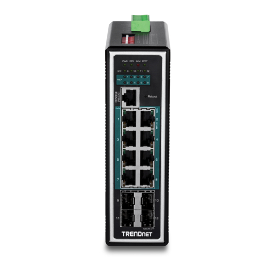
Product Overview TRENDnet’s 12-Port Hardened Industrial Gigabit PoE+ Layer 2+ Managed DIN-Rail Switch, model TI-PG1284i, has eight Gigabit PoE+ ports, four Gigabit SFP slots, and a 240W PoE budget. The switch is equipped with an IP30 rated metal enclosure and designed to withstand a high degree of vibration, shock, protection against ESD/EMI/surge, and operate within a wide temperature range (- 40 –... - Page 5 Grounding point protects equipment from external electrical surges System Monitoring Monitoring features include SNMP v1/v2c/3, MIB support, SNMP trap, RMON Groups (1, 2, 3, 9), SMTP alert, syslog, port mirroring, SFP DDMI, and ModBus/TCP. © Copyright 2016 TRENDnet. All Rights Reserved.
-
Page 6: Product Hardware Features
Grounding point/screw – The switch chassis can also be connected to a known ground point for additional safety and protection. (grounding wire not included) Note: For any unused ports or SFP slots, it is recommended to leave the rubber plugs installed during operation. © Copyright 2016 TRENDnet. All Rights Reserved. - Page 7 Calculate the maximum possible current in each power wire and common wire. Observe all electrical codes dictating the maximum current allowable for each wire size. If current go above the maximum ratings, the wiring could overheat, causing serious damage to your equipment. © Copyright 2016 TRENDnet. All Rights Reserved.
-
Page 8: Sfp Transceiver/Optical Cable Installation
Note: When inserting the cable, be sure the tab on the plug clicks into position to ensure that it is properly seated. © Copyright 2016 TRENDnet. All Rights Reserved. -
Page 9: Switch Installation
Note: The DIN-Rail bracket may already be installed to your switch when received. the bottom of the DIN-Rail and rotate away from DIN-Rail to unmount. The movable clip at the top of the DIN-Rail bracket should be on top. © Copyright 2016 TRENDnet. All Rights Reserved. -
Page 10: Install Power Supply Connections
TRENDnet User’s Guide Install power supply connections Basic IP Configuration Connect the power supply (sold separate, e.g. TRENDnet TI-S24048) to the switch terminal block as shown below. Note: Polarities V+ and V- should match between power supply and connections to switch terminal block. - Page 11 7. Configure the switch IP address settings to be within your network subnet, then click Apply.Note: You may need to modify the static IP address settings of your computer’s network adapter to IP address settings within your subnet in order to regain access to the switch. © Copyright 2016 TRENDnet. All Rights Reserved.
-
Page 12: Connect Additional Devices To Your Switch
Note: If you encounter issues connecting to your network, there may be a problem with your computer or device network settings. Please ensure that your computer or device network settings (also called TCP/IP settings) are configured properly within the network subnet your switch is connected. © Copyright 2016 TRENDnet. All Rights Reserved. -
Page 13: Accessing Switch Management Interfaces
3. Select the appropriate COM port used for connecting to the switch console. Default Gateway 0.0.0.0 Management VLAN 4. Use the following settings for the connection. Default Username admin Setting Default Value Default Password admin Terminal Emulation VT100 Baud Rate 38400 © Copyright 2016 TRENDnet. All Rights Reserved. -
Page 14: Cli Command Modes
It means these commands can be executed in this command prompt. test node. In Configure code, executing command “interface eth0” enter the eth0 Note: where the “test” is the profile name. interface node. © Copyright 2016 TRENDnet. All Rights Reserved. -
Page 15: Access Your Switch Web Management Page
1. Open your web browser and go to the IP address http://192.168.10.200. Your switch will prompt you for a user name and password. 2. Enter the user name and password. By default: User Name: admin Password: admin Note: User Name and Password are case sensitive. © Copyright 2016 TRENDnet. All Rights Reserved. -
Page 16: System Information
This field displays the name of the Switch. Boot Code This field displays the boot code version. Version Firmware Version This field displays the firmware version. Built Date This field displays the built date of the firmware. © Copyright 2016 TRENDnet. All Rights Reserved. -
Page 17: Basic Settings
This field displays the Switch’s global IP address for IPv6. request to the destination host. Refresh Click this to update the information in this screen. The –c parameter allow user to specific the packet © Copyright 2016 TRENDnet. All Rights Reserved. - Page 18 The default gateway. count is 4. The –s parameter allow eth0 ip dhcp client (disable|enable|renew) This command user to specific the configures a DHCP packet size. Valid © Copyright 2016 TRENDnet. All Rights Reserved.
- Page 19 TI-PG1284I(config-if)#ip ipv6-address default-gateway 3ffe::1234 DHCPv6 client function for the system. Disable: Use a static IP address on the switch. Enable & Renew: Use DHCPv6 client to get an IP address from DHCPv6 server. © Copyright 2016 TRENDnet. All Rights Reserved.
-
Page 20: Jumbo Frame
Select Enable to allow the Switch to automatically get an IP DHCPv6 Client address from a DHCPv6 server. Click Renew to have the Switch re-get an IP address from the DHCP server. © Copyright 2016 TRENDnet. All Rights Reserved. -
Page 21: Sntp
If the time zone and time NTP server have been changed, the Switch will Port This field specifies a port or a range of ports for configuration. repeat the query process. No default SNTP server. © Copyright 2016 TRENDnet. All Rights Reserved. - Page 22 Time after you configure the time, the Switch will apply Daylight Saving Time. Valid Range: -1200 ~ +1200. configure time date Sets the current date on the Switch. YEAR/MONTH/DAY year: 1970- Example: TI-PG1284I(config)#time ntp-server 192.5.41.41 © Copyright 2016 TRENDnet. All Rights Reserved.
- Page 23 This field displays the date you open / refresh this menu. TI-PG1284I(config)#time ntp-server enable Time and Date Setting TI-PG1284I(config)#time daylight-saving-time start-date first Monday 6 0 TI-PG1284I(config)#time daylight-saving-time end-date last Saturday 10 0 Select this option if you want to enter the system date and time Manual manually.
-
Page 24: Management Host
IP up to 3 entries. Default Settings Parameter Description The default is none, any host can manage the Switch via telnet or web browser. Management This field configures the management host. Host CLI Configuration © Copyright 2016 TRENDnet. All Rights Reserved. -
Page 25: Mac Management
The Switch uses the MAC Table to determine how to forward frames. See the following figure. enable show mac-address-table This command displays the current MAC 1. The Switch examines the received frame and learns the port from which this aging-time address table age time. © Copyright 2016 TRENDnet. All Rights Reserved. - Page 26 Port connected. Example: Apply Click Apply to take effect the settings. TI-PG1284I(config)#mac-address-table static 00:11:22:33:44:55 vlan 1 port 1 Refresh Click Refresh to begin configuring this screen afresh. Web Configuration Static MAC Table Basic Settings > MAC Management > Static MAC Settings...
-
Page 27: Mac Table
It displays CPU if it is the entry for the Switch itself. Port Notice: User can configure up to 20 entries. The CPU means that it is the Switch’s MAC. Total Counts This field displays the total entries in the MAC table. © Copyright 2016 TRENDnet. All Rights Reserved. - Page 28 This field displays the VLAN ID of the MAC address entry. Click Delete to remove this manually entered MAC address entry Action from the refusal MAC address table. Total Counts This field displays the total entries in the refusal MAC table. © Copyright 2016 TRENDnet. All Rights Reserved.
-
Page 29: Port Mirror
TI-PG1284I(config)#mirror destination port 2 4. If a port has been configured as a source port and then user configures the port TI-PG1284I(config)#mirror source ports 3-11 mode both as a destination port, the port will be removed from the source ports automatically. -
Page 30: Copyright 2016 Trendnet. All Rights Reserved
Mirror Mode specified source ports to the monitor port. Select Disable to not copy any traffic from the specified source ports to the monitor port. Apply Click Apply to take effect the settings. © Copyright 2016 TRENDnet. All Rights Reserved. -
Page 31: Port Settings
The effect of a wrap plug is to cause transmitted (output) data to be returned as receiving port memory buffers fill. Back Pressure flow control is typically used in half © Copyright 2016 TRENDnet. All Rights Reserved. -
Page 32: General Settings
Ethernet cable and shows the broken distance. interface clean cable-test result This command cleans the test result of the Ethernet cable test. interface show cable-test result This command displays the test result of the Ethernet cable test. © Copyright 2016 TRENDnet. All Rights Reserved. - Page 33 This field displays the port number. State This field displays whether the port is enabled or disabled. This field displays the speed either 10M, 100M or 1000M and the Speed/Duplex duplex mode Full or Half. © Copyright 2016 TRENDnet. All Rights Reserved.
-
Page 34: Information
Basic Settings > Port Settings > Information Parameter Description Port Select a port or a range ports you want to configure on this screen. Description Configures a meaningful name for the port(s). Port Status © Copyright 2016 TRENDnet. All Rights Reserved. -
Page 35: Advanced Settings
Priority : 0 1 2 3 4 5 6 7 Ethernet Packet: Queue : 2 0 1 3 4 5 6 7 42-1496 Type / Length Data © Copyright 2016 TRENDnet. All Rights Reserved. - Page 36 1 is often reserved for management. Priority Levels Version Type of Service Total Length PCP: Priority Code Point. Identification Flags Fragment Offset Network Priority Traffic Characteristics Time to Live Protocol Header Checksum © Copyright 2016 TRENDnet. All Rights Reserved.
- Page 37 +-----+-----+-----+-----+-----+-----+-----+-----+ Precedence Example: 111 - Network Control IP Header 110 - Internetwork Control 45 C8 . . . DSCP=50 101 - CRITIC/ECP 100 - Flash Override 011 - Flash 010 - Immediate © Copyright 2016 TRENDnet. All Rights Reserved.
- Page 38 PRIO 0 ==> COSQ 2 PRIO 1 ==> COSQ 0 PRIO 2 ==> COSQ 1 PRIO 3 ==> COSQ 3 PRIO 4 ==> COSQ 4 PRIO 5 ==> COSQ 5 PRIO 6 ==> COSQ 6 © Copyright 2016 TRENDnet. All Rights Reserved.
- Page 39 The values range from 0 (lowest configurations. priority) to 7 (highest priority). configure diffserv This command disables / enables the DiffServ Port This field displays the number of a port. (disable|enable) function. © Copyright 2016 TRENDnet. All Rights Reserved.
- Page 40 Advanced Settings > Bandwidth Control > IP DiffServ (DSCP) Priority/Queue Mapping Advanced Settings > Bandwidth Control > Priority/Queue Mapping Parameter Description Click this button to reset the priority to queue mappings to the Reset to Default defaults. © Copyright 2016 TRENDnet. All Rights Reserved.
-
Page 41: Rate Limitation
Note: Queue weights can only be changed when Weighted Round network. Schedule Mode Robin is selected. Weighted Round Robin scheduling services queues on a rotating Storm Control unit: 652pps. basis based on their queue weight (the number you configure in © Copyright 2016 TRENDnet. All Rights Reserved. - Page 42 Select the number of packets (of the type specified in the Type field) per Rate second the Switch can receive per second. TI-PG1284I(config)#storm-control rate 1 type broadcast ports 1-6 TI-PG1284I(config)#storm-control rate 1 type multicast ports 1-6 Select Broadcast - to specify a limit for the amount of broadcast packets TI-PG1284I(config)#storm-control rate 1 type DLF ports 1-6 received per second.
- Page 43 Apply Click Apply to take effect the settings. Example: Refresh Click Refresh to begin configuring this screen afresh. TI-PG1284I#configure terminal TI-PG1284I(config)#bandwidth-limit egress 1 ports 1-8 TI-PG1284I(config)#bandwidth-limit ingress 1 ports 1-8 © Copyright 2016 TRENDnet. All Rights Reserved.
-
Page 44: Igmp Snooping
VLAN. systems multicast group (224.0.0.1), has a Group Address field of 0, and has a Max Immediate Leave is only supported on IGMP Version 2 hosts). Response Time of [Query Response Interval]. © Copyright 2016 TRENDnet. All Rights Reserved. - Page 45 The unknown multicast packets will be dropped. The default port Immediate Leave state is disabled for all ports. The default port Querier Mode state is auto for all ports. The IGMP snooping Report Suppression is disabled. © Copyright 2016 TRENDnet. All Rights Reserved.
- Page 46 This command enters the interface configure gigabitethernet1/0/ node. PORTLISTS if-range igmp-immediate-leave This command enables the IGMP Snooping immediate leave function for the specific ports. © Copyright 2016 TRENDnet. All Rights Reserved.
- Page 47 Select Add and enter VLANs upon which the Switch is to IGMP Snooping perform IGMP snooping. The valid range of VLAN IDs is VLAN State between 1 and 4094. Use a comma (,) or hyphen (-) to specify © Copyright 2016 TRENDnet. All Rights Reserved.
- Page 48 Select individual ports on which to enable immediate leave. Leave Configures the maximum group for the port or a range of ports. Group Limit Apply Click Apply to apply the settings. Refresh Click this to reset the fields. © Copyright 2016 TRENDnet. All Rights Reserved.
-
Page 49: Igmp Filtering
This command removes all of the group Querier VLAN configurations. This field indicates the Querier status in vlan. State config-igmp type (deny|permit) This command configures the type of deny or permit for the group. © Copyright 2016 TRENDnet. All Rights Reserved. - Page 50 The field indicates the ports that the IGMP Filtering profile is Ports Web Configuration activated. General Settings Action Click the “Delete” button to delete the profile. Advanced Settings > IGMP Snooping > IGMP Snooping > General Settings © Copyright 2016 TRENDnet. All Rights Reserved.
- Page 51 Click Apply to apply the settings. Apply Click Apply to apply the settings. Refresh Click this to reset the fields to the last setting. Refresh Click this to reset the fields to the last setting. © Copyright 2016 TRENDnet. All Rights Reserved.
-
Page 52: Multicast Listener Discovery (Mld) Snooping
260 seconds. Querier: When enabled, the MLD snooping querier sends out periodic MLD queries that trigger MLD report messages from the switch that wants to receive IP multicast traffic. MLD © Copyright 2016 TRENDnet. All Rights Reserved. - Page 53 This command enables the MLD Snooping on the vlan. (Default: enable) mld_vlan no enable This command disables the MLD Snooping on the vlan. mld_vlan version (v1|v2) This command configures the MLD Snooping version. © Copyright 2016 TRENDnet. All Rights Reserved.
- Page 54 - Report forwards on all existing ports. vlan. Router Port Mode router-ports - Report forwards on router ports only. Remove – remove port(s) from the router port list for MLD Snooping on the vlan. © Copyright 2016 TRENDnet. All Rights Reserved.
-
Page 55: Mvr
The next depends on whether the IGMP report matches the switch configured multicast MAC address. If it matches, the switch CPU modifies the hardware address table to include this receiver port and VLAN as a forwarding destination of MVLAN. Leave Operation: © Copyright 2016 TRENDnet. All Rights Reserved. - Page 56 The MVR name should be the combination of the digit or the alphabet. The group name should be the combination of the digit or the alphabet. VLAN1 VLAN2 VLAN3 VLAN4 VLAN5 VLAN6 © Copyright 2016 TRENDnet. All Rights Reserved.
- Page 57 VLAN. Compatible : Sets the Switch not to send IGMP report. name STRING This command configures the name for the MVR. no name This command configures the default name for the MVR. © Copyright 2016 TRENDnet. All Rights Reserved.
- Page 58 Configures the source port(s) for the MVR. Normally the source ports Ports are connected to the streaming server. Receive Configures the receive port(s) for the MVR. Normally the source ports Ports are connected to the streaming client © Copyright 2016 TRENDnet. All Rights Reserved.
-
Page 59: Multicast Address
224.0.0.5 Development Purposes. send Hello packets to all OSPF routers on a network segment The OSPF AllDRouters address. Used to send OSPF routing information 224.0.0.6 to OSPF designated routers on a network segment © Copyright 2016 TRENDnet. All Rights Reserved. - Page 60 Apply Click Apply to save your changes back to the Switch. enable show mac-address-table This command displays the current multicast static/dynamic multicast address Refresh Click Refresh to begin configuring this screen afresh. entries. © Copyright 2016 TRENDnet. All Rights Reserved.
-
Page 61: Explicit Host Tracking
This field indicates the vlan of the entry. Timeout This field indicates the remaining time in the table of the entry. Host IP This field indicates the host IP which joins the multicast group. © Copyright 2016 TRENDnet. All Rights Reserved. -
Page 62: Vlan
TI-PG1284I(config)#interface 1/0/3 TI-PG1284I(config-if)#port-isolation ports 1 TI-PG1284I(config-if)#exit ; Allow the port-3 to send its ingress packets to port-1 CLI Configuration Node Command Description enable show port- This command displays the current port isolation isolation configurations. © Copyright 2016 TRENDnet. All Rights Reserved. -
Page 63: Q Vlan
VIDs, a VID of 0 is used to identify priority frames and value 4095 (FFF) is thus confining the broadcast to a specific domain. reserved, so the maximum possible VLAN configurations are 4,094. 802.1Q Port base VLAN © Copyright 2016 TRENDnet. All Rights Reserved. - Page 64 Notice: The maximum VLAN group is 4094. vlan tagged PORTLISTS This command assigns ports for tagged member of the VLAN group. The ports should be one/some of the permanent members of the vlan. © Copyright 2016 TRENDnet. All Rights Reserved.
- Page 65 This command removes a range of vlans. vlan-range add PORTLISTS This command adds a port or a range of ports to the vlans. vlan-range fixed PORTLISTS This command assigns ports for permanent member of the VLAN group. © Copyright 2016 TRENDnet. All Rights Reserved.
- Page 66 VLAN List Select a VLAN ID to configure its port tagging settings. VLAN ID This field displays the index number of the VLAN entry. Click the VLAN ID number to modify the VLAN. © Copyright 2016 TRENDnet. All Rights Reserved.
- Page 67 This field displays the Port VLAN ID number. Acceptable This field displays the type of frames allowed on the port. This will Frame either display All or VLAN Tagged Only or VLAN Untagged Only. © Copyright 2016 TRENDnet. All Rights Reserved.
-
Page 68: Garp/Gvrp
VLANs, prevents VLAN deregistration, and registers all known VLANs on other interface gvrp (disable | enable) This command disables / enables the GVRP ports on the trunk port. (Same as the static VLAN) on the specific port. © Copyright 2016 TRENDnet. All Rights Reserved. - Page 69 VLAN creation or registration on the trunk Web Configuration port. GVRP Settings Advanced Settings > VLAN > GVRP > GVRP GARP Timer Advanced Settings > VLAN > GVRP > GARP Timer © Copyright 2016 TRENDnet. All Rights Reserved.
-
Page 70: Mac-Based Vlan
Leaveall Time sent on interfaces. Leave All messages help to maintain current GVRP VLAN membership information in the network. Example: TI-PG1284I(config)#mac-vlan 00:01:02:03:04 vlan 111 priority 1 TI-PG1284I(config)#mac-vlan 00:01:02:22:04 vlan 121 priority 1 MAC-based VLAN TI-PG1284I(config)#mac-vlan 00:01:22:22:04:05 vlan 221 priority 1 The MAC base VLAN allows users to create VLAN with MAC address. -
Page 71: Protocol-Based Vlan
VLAN will be replaced with VLAN 22 and be forwarded to VLAN 22 member ports. TI-PG1284I(config)#protocol-vlan frame-type nonLLC-SNAP vlan 13 ports 3-4 TI-PG1284I(config)#protocol-vlan frame-type ethernetII ether-type 0800 vlan 14 ports 1- Notices: The 802.1Q port base VLAN should be created first. -
Page 72: Q-In-Q Vlan (Vlan Stacking)
A VLAN tag (service provider VLAN stacking or customer IEEE 802.1Q) consists of the following three fields. P: 802.1p priority VID: VLAN ID Len or Etype: Length or Ethernet frame type TPID Priority © Copyright 2016 TRENDnet. All Rights Reserved. - Page 73 TI-PG1284I(config)# vlan-stacking port-based customers with VPN tunnels between their head offices and branch offices respectively. TI-PG1284I(config)# vlan-stacking tpid-table index 2 value 88a8 Both have an identical VLAN tag for their VLAN group. The service provider can separate TI-PG1284I(config)# vlan 10...
- Page 74 TI-PG1284I(config-if)# vlan-stacking port-based role tunnel frames with the different service provider’s VID and priority. TI-PG1284I(config-if)# vlan-stacking tunnel-tpid index 2 TI-PG1284I(config)# vlan-stacking selective TI-PG1284I(config-if)# exite TI-PG1284I(config)# vlan-stacking tpid-table index 6 value 9100 TI-PG1284I(config)# exit TI-PG1284I(config)# vlan 20 TI-PG1284I# show vlan-stacking TI-PG1284I(config-vlan)# fixed 3,4...
- Page 75 This command displays the current vlan- TI-PG1284I(config)# vlan-stacking selective-qinq rule2 stacking type. TI-PG1284I(config-qinq)# cvids 30 enable show vlan-stacking selective- This command displays the selective Q- TI-PG1284I(config-qinq)# priority 5 qinq in-Q configurations. TI-PG1284I(config-qinq)# spvid 600 © Copyright 2016 TRENDnet. All Rights Reserved.
- Page 76 <0~7> based Q-in-Q. if-range vlan-stacking port-based This command sets the service if-range vlan-stacking port-based role This command sets VLAN stacking port spvid <1~4096> provider’s VID of the specified port. (tunnel|access|normal) role. © Copyright 2016 TRENDnet. All Rights Reserved.
- Page 77 Advanced Settings > VLAN > Q-in-Q > VLAN Stacking Parameter Description Select one of the three modes, Disable or Port-Based or Selective Action for the VLAN stacking. Configures the TPID Table: The TPID table has 6 entries. © Copyright 2016 TRENDnet. All Rights Reserved.
- Page 78 CVID Configures a customer’s VLAN. Priority Configures the priority for the specific ports. SPVID Configures a service provider’s VLAN. Priority Configures an 802.1Q priority for the profile. Action Enables / Disables the profile. © Copyright 2016 TRENDnet. All Rights Reserved.
-
Page 79: Dhcp Option 82
0x01 Circuit Form The DHCP server receives the packet. If the server is option-82 capable, it can use the remote ID, the circuit ID, or both to assign IP addresses and implement policies, © Copyright 2016 TRENDnet. All Rights Reserved. - Page 80 RD+%SPACE+Department+%SPACE+%HOSTNAME+%SPACE+%PORT+_+%SVLAN+.+%CVLAN The keyword must have a leading code ‘%’. For example: %HOSTNAME. The circuit sub-option result is: RD Department TI-PG1284I 1_44.32 If there are any characters following the keywords, you must add ‘+’ between the keyword and character. For example: %HOSTNAME+/.
- Page 81 Select this option to enable / disable the DHCP option 82 on State the Switch. Circuit Frame The frame ID for the circuit sub-option. Circuit Shelf The shelf ID for the circuit sub-option. Circuit Slot The slot ID for the circuit sub-option. © Copyright 2016 TRENDnet. All Rights Reserved.
-
Page 82: Dhcp Relay
DHCP messages directly to a configured DHCP server. The DHCP server sends DHCP response messages directly back to the DHCP relay agent, which then forwards them to the DHCP client. The DHCP © Copyright 2016 TRENDnet. All Rights Reserved. - Page 83 The DHCP Relay in management VLAN should be enabled. Default Settings The default global DHCP relay state is disabled. The default VLAN DHCP relay state is disabled for all VLANs. The default DHCP server is 0.0.0.0 © Copyright 2016 TRENDnet. All Rights Reserved.
-
Page 84: Dual Homing
This command disables / enables the dual- of the primary connection. (disable | enable) homing function for the system. © Copyright 2016 TRENDnet. All Rights Reserved. - Page 85 Example: TI-PG1284I(config)# link-aggregation 1 ports 5-6 TI-PG1284I(config)# link-aggregation 1 enable TI-PG1284I(config)# dual-homing primary-channel port 2 TI-PG1284I(config)# dual-homing secondary -channel trunk 1 TI-PG1284I(config)# dual-homing enable Parameter Description State Enables / disables the Dual-Homing for the Switch.
-
Page 86: Erps
If the issue does not exist, nothing is reported. no detected failure, no active automatic or external command and receiving only "NR, RB" R-APS messages), with less than 1200 km of ring fibre circumference and fewer than © Copyright 2016 TRENDnet. All Rights Reserved. - Page 87 If the Control VLAN is configured for a ring and you want to configure an instance for the erps-ring holdoff-timer This command configures the Hold-off ring. The control vlan of the instance must be same as the Control VLAN; otherwise, you Timer for the ERPS ring. (default:0 ms) © Copyright 2016 TRENDnet. All Rights Reserved.
- Page 88 Configures the instance for the ring. The Valid value is from 0 to 30. Instance 0-Disable means the ERPS is running in version 1. The control VLAN of the instance should be same as below Control VLAN. © Copyright 2016 TRENDnet. All Rights Reserved.
- Page 89 The ring ID. Ring Name The ring name. State The ring state. Revertive The ring revertive mode. Control VLAN The ring Control VLAN. Version The protocol version on the ring. Holdoff Timer The Hold-off time. © Copyright 2016 TRENDnet. All Rights Reserved.
-
Page 90: Link Aggregation
[GROUP_ID] The command adds ports to a interface PORTLISTS specific trunk group. configure no link-aggregation The commands delete ports from a [GROUP_ID] interface specific trunk group. PORTLISTS © Copyright 2016 TRENDnet. All Rights Reserved. - Page 91 Group State LACP only works on full-duplex links. Select Enable to use this static trunk group. All ports in the same trunk group must have the same media type, speed, and © Copyright 2016 TRENDnet. All Rights Reserved.
- Page 92 This command configures the default for the The default group LACP state is disabled for all groups. priority for the specific port. configure interface range This command enters the interface configure gigabitethernet1/0/ node. PORTLISTS © Copyright 2016 TRENDnet. All Rights Reserved.
- Page 93 The field identifies the port ID. Priority The field identifies the port’s LACP priority. Parameter Description Select Enable from the drop down box to enable Link Aggregation Control Protocol (LACP). State Select Disable to not use LACP. © Copyright 2016 TRENDnet. All Rights Reserved.
-
Page 94: Link Layer Discovery Protocol (Lldp)
The direct connected port’s priority of the neighbor Switch. Time To Live : 120 seconds. Oper Key The Oper key of the neighbor Switch. Port Status Port Status ---- ------- ---- ------- Internal Information 1 Enable 2 Enable © Copyright 2016 TRENDnet. All Rights Reserved. - Page 95 – Transmit the LLDP packet on the specific port only. rx-only – Receive the LLDP packet on the specific port. configure interface range This command enters the interface configure gigabitethernet1/0/ node. PORTLISTS © Copyright 2016 TRENDnet. All Rights Reserved.
- Page 96 The hold time for the Switch’s information. System The neighbor’s system description. Description Port The port range which you want to configure. System The neighbor’s capability. State Enables / disables the LLDP on these ports. Capabilities © Copyright 2016 TRENDnet. All Rights Reserved.
-
Page 97: Loop Detection
The default Port Loop-Detection state is disabled for all ports. interface loop-detection recovery This command enables / disables the The default Port Loop-Detection status is unblocked for all ports. (disable | enable) recovery function on the port. © Copyright 2016 TRENDnet. All Rights Reserved. - Page 98 Select Enable to reactivate the port automatically after the Loop Recovery designated recovery time has passed. Specify the recovery time in minutes that the Switch will wait Recovery Time before reactivating the port. This can be between 1 to 60 minutes. © Copyright 2016 TRENDnet. All Rights Reserved.
-
Page 99: Modbus
Read Input access Registers Registers Word 0 Lo byte = ‘W’ (16-bit Word 1 Hi byte = ‘I’ Physical Output Read Holding Not support access) Registers Word 1 Lo byte = ‘T’ Registers © Copyright 2016 TRENDnet. All Rights Reserved. - Page 100 3 words Ethernet MAC Address 0x0004: 10M-Half-FC_OFF Ex: MAC = 00-01-02-03-04-05 0x0005: 100M-Full-FC_ON Word 0 Hi byte = 0 x 00 0x0006: 100M-Full-FC_OFF Word 0 Lo byte = 0 x 01 0x0007: 100M-Half-FC_ON © Copyright 2016 TRENDnet. All Rights Reserved.
- Page 101 0x0480 to 2 words Port 1 to 10 Tx Error Packets Word 1 Hi byte = MAC3 0x0493 Ex: port 1 Tx Error Packet Amount = Word 2 Lo byte = MAC4 0x87654321 © Copyright 2016 TRENDnet. All Rights Reserved.
- Page 102 0x051e 1 word Primary Port Status of Xpress-ring1 0x0000 : link down 0x0001 : forwarding 0x0002 : blocking 0x051f 1 word Secondary Port Status of Xpress-ring1 0x0000 : link down 0x0001 : forwarding © Copyright 2016 TRENDnet. All Rights Reserved.
-
Page 103: Poe (Power Over Ethernet)
PD: A powered device (PD) is a device such as an access point or a switch, that supports None 10°C with two modes (four pairs) ambient PoE (Power over Ethernet) so that it can receive power from another device through a simultaneously active operating 10/100 Mbps Ethernet port. temperature © Copyright 2016 TRENDnet. All Rights Reserved. - Page 104 PoE function for the specific port. critical : The highest priority. Default Settings high : The middle priority. State : Disabled low : The lowest priority. Total Power(W) © Copyright 2016 TRENDnet. All Rights Reserved.
- Page 105 If the port’s check configuration is NO for a specific day, the Switch will not perform action for the specific port. If the port’s check configuration is YES for a specific day, the Switch © Copyright 2016 TRENDnet. All Rights Reserved.
- Page 106 Check defined time period. interface poe schedule week This command configures the PoE (Sun|Mon|Tue|Wed|Thu|Fri|Sat) schedule start-time and end-time Time (Hour) start-time VALUE end-time VALUE on a specific day on the specific action (enable|disable) © Copyright 2016 TRENDnet. All Rights Reserved.
- Page 107 All: Send an alarm message to inform the administrator and then reboot the PD. Alarm: Just send an alarm message to inform the administrator. None: Keep Ping the remote PD but does nothing further. Reboot: Cut off the power of the PoE port, make PD rebooted. © Copyright 2016 TRENDnet. All Rights Reserved.
- Page 108 This command enables / disables of the Action Power Device cannot respond the keep-a-live probe packet. The (enable|disable) Power Delay function for the range of options have Reboot / Alarm / All /None. ports. © Copyright 2016 TRENDnet. All Rights Reserved.
-
Page 109: Ptp (Ieee-1588 V2)
Member sends “DReq (Delay Request)” message to master Refresh Click Refresh to begin configuring this screen afresh. Master sends “Dresp (Delay Response)” message to member d. Member will adjust its clock by using parameters in above messages. Power Delay Status © Copyright 2016 TRENDnet. All Rights Reserved. - Page 110 ID default domain clock and domain ID (0). assigns default priority value (128). configure ptp domain <Domain-ID> This command creates a specified ptp_config clock-priority2 <Value> This command domain in PTP. assigns specified © Copyright 2016 TRENDnet. All Rights Reserved.
- Page 111 This command ptp_config_port no acceptable-master enable This command enables two step deletes PTP port in clock mode in PTP domain from domain. acceptable master list. ptp_config no two-step-clk This command disables two step © Copyright 2016 TRENDnet. All Rights Reserved.
- Page 112 Creating PTP Domain: This command is used to create a new PTP domain and ptp_config_port vlan <VLAN LIST> This command provides us command prompt as “config-ptp” node. configures specified TI-PG1284I(config)#ptp domain 1 © Copyright 2016 TRENDnet. All Rights Reserved.
- Page 113 PTP domain and adds 128 as domain’s first priority. Disabling Two Step Clock from PTP Domain: This command is used to disable two TI-PG1284I(config-ptp)#no clk-priority1 step clock mode from PTP domain. TI-PG1284I(config-ptp)#no two-step-clk © Copyright 2016 TRENDnet. All Rights Reserved.
- Page 114 Deleting Announce Interval from PTP Port: This command is used to delete existing PTP Status : Disable announce interval from PTP port and adds 1 (default value) as announce interval in PTP Primary Domain : 0(Default) PTP port. TI-PG1284I(config-ptp-port)#no announce interval © Copyright 2016 TRENDnet. All Rights Reserved.
- Page 115 Domain ID : 1 ------------------------------------------ Domain Status : Disabled Slave Mode : Disabled Path Trace Mode : Disabled Clock Mode : Forward(Default) Two Step Clock Mode : Disabled Clock Priority_1 : 128(default) Clock Priority_2 : 128(default) © Copyright 2016 TRENDnet. All Rights Reserved.
- Page 116 The priority of the clock 1 priority of the domain. Two Step Clock Enable –enables two step clock mode in PTP domain. Clock Priority_2 The priority of the clock priority2 of the domain. © Copyright 2016 TRENDnet. All Rights Reserved.
- Page 117 (0). Clock Priority_2 The priority of the clock priority2 of the domain. Add - configures to send periodical announce messages in Announce Interval specified intervals in PTP port. © Copyright 2016 TRENDnet. All Rights Reserved.
-
Page 118: Static Route
Command Description ipv4 address This command assigns a specified IPv4 enable show ip forwarding This command displays the current interface A.B.C.D/M interface route to the interface. status configuration of the ip forwarding status. © Copyright 2016 TRENDnet. All Rights Reserved. - Page 119 TI-PG1284I(config)#interface vlan 1 <IPv6_ADDR> TI-PG1284I(config-if-vlan-l3)# no ipv4 route This command deletes a specified IPv4 static TI-PG1284I(config-if-vlan-l3)#ipv4 address 192.168.20.1/24 interface A.B.C.D/M A.B.C.D route from an interface vlan. TI-PG1284I(config-if-vlan-l3)#ipv6 address 1234:ab::ccdd/120 © Copyright 2016 TRENDnet. All Rights Reserved.
- Page 120 TI-PG1284I(config-if-vlan-l3)#no ipv6 address 1234:ab::ccdd/120 1234:ab::ccdd Parameter Description Global Settings IP Forwarding Enables / disables the IP forwarding globally. IP ARP Proxy Enables / disables the route to act as an ARP proxy globally. © Copyright 2016 TRENDnet. All Rights Reserved.
-
Page 121: Stp
The root bridge is the base of the spanning tree. Path cost is the cost of transmitting a frame onto a LAN through that port. The recommended cost is assigned according to the speed of the link to which a © Copyright 2016 TRENDnet. All Rights Reserved. - Page 122 The allowed range is 6 to 40 seconds. The Spanning Tree Protocol (STP) is defined in the IEEE Standard 802.1D. As the name suggests, it creates a spanning tree within a mesh network of connected layer-2 bridges © Copyright 2016 TRENDnet. All Rights Reserved.
- Page 123 Disabled - Not strictly part of STP, a network administrator can manually The valid value is from 1 to 200000000. Higher cost paths are more likely to be disable a port blocked by STP if a network loop is detected. © Copyright 2016 TRENDnet. All Rights Reserved.
- Page 124 Per port STP state : enabled. configure spanning-tree This command configures the bridge times Per port Priority : 128. algorithm-timer (forward-delay,max-age,hello-time). Per port Edge port : disabled. forward-time TIME © Copyright 2016 TRENDnet. All Rights Reserved.
- Page 125 This command configures enables/disables (disable|enable) bpdufilter the bpdufilter function for the specific port. if-range spanning-tree This command configures enables/disables (disable|enable) bpduguard the bpduguard function for the specific port. (disable|enable) © Copyright 2016 TRENDnet. All Rights Reserved.
- Page 126 This is the maximum time (in seconds) the Switch can wait without Max Age receiving a BPDU before attempting to reconfigure. All Switch ports (except for designated ports) should receive BPDUs at regular intervals. © Copyright 2016 TRENDnet. All Rights Reserved.
- Page 127 BPDU Filter Enables/Disables the BPDU filter function for the specific port. BPDU Guard Enables/Disables the BPDU guard function for the specific port. ROOT Guard Enables/Disables the BPDU root guard function for the specific port. © Copyright 2016 TRENDnet. All Rights Reserved.
- Page 128 This is the MAC address of the current bridge. Priority is used in determining the root switch, root port and Priority designated port. The switch with the highest priority (lowest numeric value) becomes the STP root switch. If all switches have © Copyright 2016 TRENDnet. All Rights Reserved.
- Page 129 IST port state (MST ports at the boundary are in the forwarding state only when the IST port is forwarding). An IST port at the boundary can have any port role except a backup port role. © Copyright 2016 TRENDnet. All Rights Reserved.
- Page 130 TCN BPDUs or version 3 MSTP BPDUs on a boundary port. A boundary port connects hello-time MSTP. to a LAN, the designated switch of which is either a single spanning-tree switch or a switch The default hello time is 2 seconds. with a different MST configuration. © Copyright 2016 TRENDnet. All Rights Reserved.
- Page 131 TI-PG1284I(config-mst)#name MSTP TI-PG1284I(config-mst)#revision 1 configure spanning-tree mst This command enters the MSTP configure configuration node. TI-PG1284I(config-mst)#instance 1 vlan 1-10 configure no spanning-tree mst This command resets all of configurations for configuration the MSTP. © Copyright 2016 TRENDnet. All Rights Reserved.
- Page 132 Instance Selects an instance which you want to configure. forward frames. In addition, each port needs time to listen for conflicting information that would make it return to a blocking © Copyright 2016 TRENDnet. All Rights Reserved.
- Page 133 Root Hello Time, Root Maximum Age and Root Forwarding Delay. Priority Configures the priority for the specific port. Port Selects a port or a range of ports that you want to configure. Active Enables/Disables the spanning tree function for the specific port. © Copyright 2016 TRENDnet. All Rights Reserved.
- Page 134 Hello Time, Max Age and Forwarding Delay. This is the time (in seconds) the root switch will wait before Forward Delay changing states. Root Port This is the port to the root bridge. © Copyright 2016 TRENDnet. All Rights Reserved.
-
Page 135: Xpress Ring
: 01:80:c2:ff:ff:f0. secondary-port PORTID Notice: If the global xpress ring is disabled Role : Forwarder. or ring state is disabled, you can input 0 to Primary Port : None. reset the primary port. © Copyright 2016 TRENDnet. All Rights Reserved. - Page 136 Configures the last byte of the destination MAC for the ring. MAC(Last byte) Role Configures the role for the ring. Primary Port Configures the primary port for the ring. Secondary Port Configure the secondary port for the ring. Xpress Ring Status © Copyright 2016 TRENDnet. All Rights Reserved.
-
Page 137: Security
The packet is a DHCP server packet (for example, OFFER, ACK, or NACK). The source MAC address and source IP address in the packet do not match any of © Copyright 2016 TRENDnet. All Rights Reserved. - Page 138 When the global state is disabled, the DHCP Snooping on the Switch is disabled even per VLAN states are enabled. When the global state is enabled, user must enable per VLAN states to enable the DHCP Snooping on the specific VLAN. © Copyright 2016 TRENDnet. All Rights Reserved.
- Page 139 DHCP Client-1: ipconfig /renew count for the specific ports. DHCP Client-1 can get an IP address. if-range no dhcp-snooping host This command configures the maximum host count to default for the specific ports. © Copyright 2016 TRENDnet. All Rights Reserved.
- Page 140 Select Enable to use DHCP snooping on the Switch. You still have to enable DHCP snooping on specific VLANs and specify State trusted ports. Note: The Switch will drop all DHCP requests if you enable DHCP snooping and there are no trusted ports. © Copyright 2016 TRENDnet. All Rights Reserved.
- Page 141 Click Apply to configure the settings. provide DHCP services to different distinct groups of clients, the valid DHCP server’s packets will be passed to the client. Refresh Click Refresh to begin configuring this screen afresh. © Copyright 2016 TRENDnet. All Rights Reserved.
-
Page 142: Binding Table
TRENDnet User’s Guide TI-PG1284I#configure terminal Server Screening List TI-PG1284I(config)#dhcp-snooping binding mac 00:11:22:33:44:55 ip 1.1.1.1 vlan 1 port This field displays the index number of the DHCP server entry. Click the number to modify the entry. TI-PG1284I(config)#no dhcp-snooping binding mac 00:11:22:33:44:55... -
Page 143: Arp Inspection
ARP cache or before it forwards the packet to the appropriate destination. Trusted and untrusted port This setting is independent of the trusted and untrusted setting of the DHCP © Copyright 2016 TRENDnet. All Rights Reserved. - Page 144 When the global state is disabled, the ARP Inspection on the Switch is disabled even per VLAN states are enabled. When the global state is enabled, user must enable per VLAN states to enable the ARP Inspection on the specific VLAN. © Copyright 2016 TRENDnet. All Rights Reserved.
- Page 145 ARP packet, and it automatically creates a SYSLOG and drop this ARP packet. The SYSLOG event happens on the first time. Select All Click this to set all ports to trusted. © Copyright 2016 TRENDnet. All Rights Reserved.
- Page 146 This field displays the current number of MAC address filters that Total were created because the Switch identified unauthorized ARP packets. Parameter Description Filter Age Time This setting has no effect on existing MAC address filters. © Copyright 2016 TRENDnet. All Rights Reserved.
-
Page 147: Access Control List (Acl)
Command: destination ip host IPADDR (disable|drop|permit) disable – disable the profile. 3. Filter a range of source IP address. drop – If packets match the profile, the Command: source ip IPADDR IPADDR packets will be dropped. © Copyright 2016 TRENDnet. All Rights Reserved. - Page 148 VLAN from the profile. ether type from the profile. source interface This command configures the source source mac host This command configures the source MAC PORT_ID interface for the profile. MACADDR and mask for the profile. © Copyright 2016 TRENDnet. All Rights Reserved.
- Page 149 VLAN Configures the VLAN of the packets that you want to filter. Ethernet Type: any Source IP Address: any Source MAC Configures the source MAC of the packets that you want to filter. © Copyright 2016 TRENDnet. All Rights Reserved.
-
Page 150: 147
If the credentials IP Protocol are valid (in the authentication server database), the supplicant (client device) is allowed TCP:0x06. UDP:0x11. to access resources located on the protected side of the network. © Copyright 2016 TRENDnet. All Rights Reserved. - Page 151 : Users can access network without authentication. without interacting with a network authentication server. However, there is a limit on the force-unauthorized : Users cannot access network. number of users you may authenticate in this way. Quiet Period: © Copyright 2016 TRENDnet. All Rights Reserved.
- Page 152 The default port Supp timeout is 30 seconds for all ports. configure no dot1x radius This command removes the secondary radius The default port Server timeout is 30 seconds for all ports. secondary-server-ip server. © Copyright 2016 TRENDnet. All Rights Reserved.
- Page 153 This command configures the server-timeout timeout value on the port. interface dot1x timeout reauth- This command configures the re-auth-period period value on the port. © Copyright 2016 TRENDnet. All Rights Reserved.
- Page 154 Switch itself to Radius Server is down. authenticate. Apply Click Apply to add/modify the settings. However, only a certain number of accounts can exist at one time. © Copyright 2016 TRENDnet. All Rights Reserved.
- Page 155 802.1x port authentication. Port Status Specify if a subscriber has to periodically re-enter his or her Re-authentication Port This field displays the port number. username and password to stay connected to the port. © Copyright 2016 TRENDnet. All Rights Reserved.
-
Page 156: Port Security
This field displays how long the Switch will wait before CLI Configuration Server timeout communicating with the client. Node Command Description enable show port-security This command displays the current port security configurations. © Copyright 2016 TRENDnet. All Rights Reserved. -
Page 157: Tacacs
Port Security Settings TACACS+ packet body encryption will be supported. Single Tacacs+ server will be support. Port Security Select Enable/Disable to permit Port Security on the Switch. © Copyright 2016 TRENDnet. All Rights Reserved. - Page 158 (command must be completed). The reason is only the command after user HIT the ENTER is only send to TACACS+ server for authorization or accounting. So if this command is partial then subsequently authorization or accounting fails. © Copyright 2016 TRENDnet. All Rights Reserved.
- Page 159 To disable the authentication in enable Tacacs+ State :disabled enable-mode enable mode. Tacacs+ line-console mode :disabled configure tacacs-plus authentication To enable the authentication enable Authentication Login mode :disabled Local: disabled enable-mode local enable local mode © Copyright 2016 TRENDnet. All Rights Reserved.
- Page 160 Configures the TACACS server’s IP. TACACS Server Configures the server key for the TACACS server. Server Key Parameter Description State Enables / Disables the Tacacs+ service. Authentication Enables / Disables the authentication in login mode. Login Mode © Copyright 2016 TRENDnet. All Rights Reserved.
-
Page 161: Monitor
------- ------- -------- ------------- --------- BOARD 44.0 44.2 24.0 80.0 Normal 49.2 49.2 26.5 80.0 Normal 57.5 57.5 30.0 80.0 Normal Voltage(V) Current MAX MIN Threshold Status -------------- --------- ------- -------- ------------ -------- © Copyright 2016 TRENDnet. All Rights Reserved. -
Page 162: Port Statistics
Rx Drops The field displays the received drop count. Tx Drops The field displays the transmitted drop count. Example: TI-PG1284I#show port-statistics Refresh Click this button to refresh the screen quickly. Packets Bytes Errors Drops © Copyright 2016 TRENDnet. All Rights Reserved. -
Page 163: Port Utilization
Click this button to refresh the screen quickly. Parameter Description Port Select a port or a range of ports to display their RMON statistics. Show Show them. Clear Clear the RMON statistics for the port or a range of ports. © Copyright 2016 TRENDnet. All Rights Reserved. -
Page 164: Sfp Information
1000 Enabled 1 Fiber Cable To indicate if the fiber cable is connected. 9 Disabled Normal Bcast 1000 Enabled 1 Connector Code of optical connector type. 10 Disabled Normal Bcast 1000 Enabled 1 © Copyright 2016 TRENDnet. All Rights Reserved. - Page 165 Port The port range which you want to configure. (bcast|mcast|bcast+mcast) the port. bcast – Broadcast packet. State Enables / disables the traffic monitor function on these ports. mcast – Multicast packet. © Copyright 2016 TRENDnet. All Rights Reserved.
-
Page 166: Management
User need only input the network ID and leave the host ID to 0. If user has input the host ID, such as 192.168.1.102, the system will reset the host ID, such as 192.168.1.0 Note: Allow user to configure the community string and rights only. © Copyright 2016 TRENDnet. All Rights Reserved. - Page 167 Default Settings Example: SNMP : disabled. TI-PG1284I#configure terminal System Location : TI-PG1284I. (Maximum length 64 characters) TI-PG1284I(config)#snmp enable System Contact : None. (Maximum length 64 characters) System Name : None. (Maximum length 64characters) TI-PG1284I(config)#snmp community public rw trusted-host 192.168.200.106/24 ...
- Page 168 Click Delete to remove a specific Community String. String management station (the SNMP manager) and the device (the SNMP agent). The community string is included in every packet that is transmitted between the SNMP manager and the SNMP agent. © Copyright 2016 TRENDnet. All Rights Reserved.
-
Page 169: Snmp Trap
This field displays the IP address of the remote trap station. snmp view VIEWNAME configure To identify the subtree. This field displays the version of Simple Network Management STRINGS (included|excluded) Version Protocol in use. v1 or v2c. © Copyright 2016 TRENDnet. All Rights Reserved. - Page 170 Select the security level of the v3 user to use. noauth means no authentication and no encryption. Security Level auth means messages are authenticated but not encrypted. priv means messages are authenticated and encrypted. © Copyright 2016 TRENDnet. All Rights Reserved.
- Page 171 Enter the v3 view name for creating an entry in the SNMPv3 MIB View Name view table. SNMPv3 Group Status The OID defining the root of the subtree to add to (or exclude View Subtree from) the named view. © Copyright 2016 TRENDnet. All Rights Reserved.
-
Page 172: Auto Provision
If upgrade configutation succeeded and Specific_Configuration_Reboot =1, let The contents of the file are listed below: reboot_flag=1. AUTO_PROVISION_VER=1 Firmware_Upgrade_State=1 10. If reboot_flag=1, save running configuration and reboot the switch; otherwise, wait Firmware_Version=8648P-999-1.1.0.S0 24 hours and go back to step 1. © Copyright 2016 TRENDnet. All Rights Reserved. -
Page 173: Mail Alarm
Firmware Upgrade : The system firmware image has auto-provision no folder The command configurations the folder to been updated. default. User Login : A user login the system. © Copyright 2016 TRENDnet. All Rights Reserved. - Page 174 Secure (SSL) configure mail-alarm (disable|enable) This command disables / enables the Mail Alarm function. Non-Encrypted AUTH POP3 Server (Incoming configure mail-alarm auth-account This command configures the Mail Messages) Secure (SSL) server authentication account. © Copyright 2016 TRENDnet. All Rights Reserved.
-
Page 175: Maintenance
This command downloads a new copy of config <URL PATH> configuration file from TFTP server. Parameter Description Where <URL PATH> can be: State Enable / disable the Mail Alarm function. ftp://user:pass@192.168.1.1/file http://192.168.1.1/file © Copyright 2016 TRENDnet. All Rights Reserved. - Page 176 Follow the steps below to load the configuration file from your PC to the Switch. Select the “Upload configurations file to your Switch”. Select the full path to your configuration file. Click the Upload button to start the process. © Copyright 2016 TRENDnet. All Rights Reserved.
- Page 177 Click “Reset configuration” in web management or do cli command, reload default-config. Click “Upload configuration” in web management or do cli command, In the Reboot screen, click the Reboot button. The following screen displays. “archive download-config xxx”. © Copyright 2016 TRENDnet. All Rights Reserved.
- Page 178 This command enables the web on the Switch. Refresh Click this button to reset the fields to the last setting. configure no web server This command disables the web on the Switch. Server Status © Copyright 2016 TRENDnet. All Rights Reserved.
-
Page 179: System Log
Select Alert/Critical/Error/Warning/Notice/Information to Log Level choose which log message to want see. configure syslog-server ipv4-ip The command configures the syslog server’s IP IPADDR address in IPv4 format. Apply Click Apply to add/modify the settings. © Copyright 2016 TRENDnet. All Rights Reserved. -
Page 180: User Account
The Switch allows users to create up to 6 user account. The user name and the password should be the combination of the digit or the alphabet. The last admin user account cannot be deleted. © Copyright 2016 TRENDnet. All Rights Reserved. - Page 181 User This field displays the password. Password User This field displays the associated group. Authority Click the Delete button to remove the user account. Action Note: You cannot delete the last admin accounts. © Copyright 2016 TRENDnet. All Rights Reserved.
-
Page 182: Technical Specifications
Fast Ethernet: 100 Mbps (half-duplex), 200 Mbps (full-duplex) MIB II RFC 1213 Gigabit Ethernet: 2000 Mbps (full-duplex) Bridge MIB RFC 1493 SX/LX: 2000 Mbps (full-duplex) Ethernet Interface MIB RFC 1643 © Copyright 2016 TRENDnet. All Rights Reserved. - Page 183 MLD v1, v2 Dual redundant power inputs IGMP filtering/querier/proxy Alarm relay triggered by power and ports/slots failure Static multicast address Surge/ESD protection Up to 256 multicast entries © Copyright 2016 TRENDnet. All Rights Reserved.
- Page 184 ESD (Ethernet) Protection: 8KV DC Surge (Power) Protection: 6KV DC MTBF 99,992 hrs @ 75 °C 322,805 hrs @ 25 °C Operating Temperature - 40 to 75 °C (-40 to 167 °F) © Copyright 2016 TRENDnet. All Rights Reserved.
-
Page 185: Troubleshooting
Then click Use the following IP address, and make sure to assign your network adapter an IP address in the subnet of 192.168.10.x. Click OK Note: If you are experiencing difficulties, please contact your computer or operating system manufacturer for assistance. © Copyright 2016 TRENDnet. All Rights Reserved. -
Page 186: Appendix
From the Location drop-down list, select Automatic. 2. In the Network Preference window, next to "Show:", select Network Status. You'll see d. Select and view your Ethernet connection. your network status and your IP address settings displayed. © Copyright 2016 TRENDnet. All Rights Reserved. - Page 187 2. Select Ethernet from the list on the left. Example: ping –c 4 192.168.10.100 3. Click the Advanced button. 3. On the Ethernet tab, the Ethernet ID is your MAC Address. © Copyright 2016 TRENDnet. All Rights Reserved.
- Page 188 Country Code selection feature to be disabled for products marketed to the US/CANADA CE Mark Warning This is a Class A product. In a domestic environment, this product may cause radio interference, in which case the user may be required to take adequate measures. © Copyright 2016 TRENDnet. All Rights Reserved.
- Page 189 TI-PG1284i TRENDnet User’s Guide reikalavimus ir kitas 2014/30/EU ir 2004/108/EB Direktyvos TRENDnet tímto prohlašuje, že tento TI-PG1284I je ve shodě se Česky [Czech] nuostatas. základními požadavky a dalšími příslušnými ustanoveními směrnice 2014/30/EU a 2004/108/ES. Hierbij verklaart TRENDnet dat het toestel TI-PG1284I in Nederlands overeenstemming is met de essentiële eisen en de andere...
- Page 190 An RMA number is required in order to initiate warranty service support the event that the RMA unit needs to be replaced, TRENDnet may replace it with a for all TRENDnet products. Products that are sent to TRENDnet for RMA service must refurbished product of the same or comparable model.
- Page 191 OF SUCH DAMAGES, AND LIMITS ITS LIABILITY TO REPAIR, REPLACEMENT, OR REFUND evidence of the original purchaser's date of purchase. Replacement products may be OF THE PURCHASE PRICE PAID, AT TRENDNET'S OPTION. THIS DISCLAIMER OF LIABILITY refurbished or contain refurbished materials. If TRENDnet, by its sole determination, is...
Need help?
Do you have a question about the TI-PG1284i and is the answer not in the manual?
Questions and answers