Table of Contents
Advertisement
Quick Links
Advertisement
Table of Contents

Related Manuals for YASKAWA Sigma-V-FT Series


Summary of Contents for YASKAWA Sigma-V-FT Series
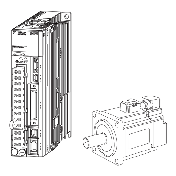
- Page 1 AC Servo Drives Series USER’S MANUAL Model: FT001 Rotational Motor/Analog Voltage and Pulse Train Reference SGDV-01FT001 SERVOPACK SGMMV/SGMJV/SGMAV/SGMPS/SGMGV/SGMSV/SGMCV/SGMCS Servomotor Outline Adjustments MANUAL NO. SIEP S800000 97F...
- Page 2 Yaskawa. No patent liability is assumed with respect to the use of the information contained herein. Moreover, because Yaskawa is con- stantly striving to improve its high-quality products, the information contained in this manual is subject to change without notice.
-
Page 3: About This Manual
About this Manual This manual contains information that is required to design and adjust Σ-V-FT-series FT001 servo system. An FT001 rotational servo system provides an analog voltage and pulse train reference interface and improved vibration suppression. Keep this manual in a location where it can be accessed for reference whenever required. When you use a Σ-V-FT-series FT001 servo system, read this manual together with the Σ-V Series User’s Manual Design and Maintenance, Rotational Motor/Analog Voltage and Pulse Train Reference. - Page 4 (cont’d) Σ-V Series User’s Manual Design and Maintenance, Rotational Motor/Analog Voltage Item This Manual and Pulse Train Reference (Manual No.: SIEP S800000 45) Type of Adjustments and Basic Adjustment – Procedure Tuning-less Function – Advanced Autotuning – (Fn201) Advanced Autotuning by –...
- Page 5 Description of Technical Terms The following table shows the meanings of terms used in this manual. Term Meaning Cursor Input position indicated by Digital Operator Σ-V Series rotary servomotors (SGMMV, SGMJV, SGMAV, SGMPS, SGMGV, or SGMSV), and Σ-V Series direct drive servomotors (SGMCV Servomotor or SGMCS) Σ-V-FT Series FT001 servo amplifier...
- Page 6 Notation Used in this Manual • Notation for Reverse Signals The names of reverse signals (i.e., ones that are valid when low) are written with a forward slash (/) before the signal name. Notation Example BK = /BK • Notation for Parameters The notation depends on whether the parameter requires a value setting (parameter for numeric settings) or requires the selection of a function (parameter for selecting functions).
- Page 7 Manuals Related to the Σ-V Series Refer to the following manuals as required. Selecting Trial Maintenance Models and Ratings and System Panels and Trial Operation Name Peripheral Specifications Design Wiring Operation and Servo Inspection Devices Adjustment Σ-V Series Product Catalog ...
-
Page 8: Safety Precautions
Safety Precautions This section describes important precautions that must be followed during storage, transportation, installation, wiring, operation, maintenance, inspection, and disposal. Be sure to always observe these precautions thor- oughly. WARNING • Never touch any rotating servomotor parts during operation. Failure to observe this warning may result in injury. - Page 9 Storage and Transportation CAUTION • Do not store or install the product in the following locations. Failure to observe this caution may result in fire, electric shock, or damage to the equipment. • Locations subject to direct sunlight • Locations subject to temperatures outside the range specified in the storage/installation temperature condi- tions •...
- Page 10 Wiring CAUTION • Be sure to wire correctly and securely. Failure to observe this caution may result in motor overrun, injury, or malfunction. • Do not connect a commercial power supply to the U, V, or W terminals for the servomotor connec- tion.
- Page 11 Operation CAUTION • Always use the servomotor and SERVOPACK in one of the specified combinations. Failure to observe this caution may result in fire or malfunction. • Conduct trial operation on the servomotor alone with the motor shaft disconnected from the machine to avoid accidents.
- Page 12 • The drawings presented in this manual are typical examples and may not match the product you received. • If the manual must be ordered due to loss or damage, inform your nearest Yaskawa representative or one of the offices listed on the back of this manual.
-
Page 13: Warranty
6. Events for which Yaskawa is not responsible, such as natural or human-made disasters (2) Limitations of Liability 1. Yaskawa shall in no event be responsible for any damage or loss of opportunity to the customer that arises due to failure of the delivered product. - Page 14 2. The customer must confirm that the Yaskawa product is suitable for the systems, machines, and equipment used by the customer. 3. Consult with Yaskawa to determine whether use in the following applications is acceptable. If use in the application is acceptable, use the product with extra allowance in ratings and specifications, and provide safety measures to minimize hazards in the event of failure.
- Page 15 Compliance with UL Standards, EU Directives, UK Regulations, Other Safety Standards and China Energy Efficiency Regulations North American Safety Standards (UL) North American Safety Standards Product Model (UL File No.) SERVOPACK SGDV UL508C (E147823) • SGMMV • SGMJV UL 1004-1 •...
- Page 16 EU Directives Product Model EU Directives Harmonized Standards Machinery Directive EN ISO 13849-1: 2015 2006/42/EC EN 55011 Group 1, Class A EMC Directive EN 61000-6-2 2014/30/EU EN 61000-6-4 SERVOPACK SGDV EN 61800-3 (Category C2, Second environment) Low Voltage Directive EN 61800-5-1 2014/35/EU RoHS Directive...
- Page 17 UK Conformity Assessed (UKCA) Product Model UK Regulations Designated Standards Supply of Machinery (Safety) Regulations EN ISO 13849-1: 2015 S.I. 2008/1597 EN 55011 Group 1, Class A Electromagnetic Compatibility EN 61000-6-2 Regulations EN 61000-6-4 S.I. 2016/1091 EN 61800-3 (Category C2, Second environment) SERVOPACK SGDV Electrical Equipment (Safety)
- Page 18 Safety Standards Product Model Safety Standards Standards EN ISO 13849-1: 2015 Safety of Machinery EN 60204-1 SERVOPACK SGDV EN 61508 series Functional Safety EN 61800-5-2 Functional Safety EMC EN 61326-3-1 • Safety Performance Items Standards Performance Level Safety Integrity Level EN 61508 SIL2 PFH = 1.7×10...
-
Page 19: Table Of Contents
Contents About this Manual ............iii Safety Precautions. - Page 21 Outline 1.1 Σ-V-FT-series FT001 ......... 1-2 1.2 SERVOPACK Ratings and Specifications .
-
Page 22: Chapter 1 Outline
1 Outline Σ-V-FT-series FT001 A Σ-V-FT-series FT001 SERVOPACK provides improved vibration suppression over a Σ-V-series SERVOPACK. Vibration is suppressed when stopping and during operation, and positioning time is shortened. -
Page 23: Servopack Ratings And Specifications
1.2 SERVOPACK Ratings and Specifications SERVOPACK Ratings and Specifications This section describes the ratings and specifications of SERVOPACKs. 1.2.1 Ratings Ratings of SERVOPACKs are as shown below. (1) SGDV with Single-phase, 100-V Rating SGDV (Single Phase, 100 V) Continuous Output Current [Arms] 0.66 0.91 Instantaneous Max. -
Page 24: Basic Specifications
1 Outline 1.2.2 Basic Specifications 1.2.2 Basic Specifications Basic specifications of SERVOPACKs are shown below. Drive Method Sine-wave current drive with PWM control of IGBT Feedback Encoder: 13-bit (incremental), 17-bit, 20-bit (incremental/absolute) Surrounding Air Tem- 0°C to +55°C perature Storage Temperature -20°C to +85°C Ambient Humidity 90% RH or less... - Page 25 1.2 SERVOPACK Ratings and Specifications (cont’d) Phase A, B, C: line driver Encoder Output Pulse Encoder output pulse: any setting ratio Fixed Input SEN signal Number of 7 ch Channels • Servo ON (/S-ON) • Proportional control (/P-CON) • Forward run prohibited (P-OT), reverse run prohibited (N-OT) •...
-
Page 26: Control Specifications
1 Outline 1.2.3 Control Specifications (cont’d) Activated when a servo alarm or overtravelling occurs or when the power Dynamic Brake (DB) supply for the main circuit or servomotor is OFF. Regenerative Processing Included Dynamic brake stop, deceleration to a stop, or free run to a stop at P-OT or Overtravel Prevention (OT) N-OT Overcurrent, overvoltage, insufficient voltage, overload, regeneration error,... -
Page 27: Servopack Model Designation
1.3 SERVOPACK Model Designation SERVOPACK Model Designation This section shows SERVOPACK model designation. 11th + 12th + 13th + 8th + 9th + 1st + 2nd + 5th + 6th 14th + 15th digits 10th digits digit digit 3rd digits digits FT001 SGDV... - Page 28 1 Outline...
- Page 29 Adjustments 2.1 Type of Adjustments and Basic Adjustment Procedure ....2-2 2.1.1 Adjustments ............2-2 2.1.2 Basic Adjustment Procedure .
-
Page 30: Chapter 2 Adjustments
2 Adjustments 2.1.1 Adjustments Type of Adjustments and Basic Adjustment Procedure This section describes type of adjustments and the basic adjustment procedure. 2.1.1 Adjustments Adjustments (tuning) are performed to optimize the responsiveness of the SERVOPACK. The responsiveness is determined by the servo gain that is set in the SERVOPACK. The servo gain is set using a combination of parameters, such as speed loop gain, position loop gain, filters, friction compensation, and moment of inertia ratio. - Page 31 2.1 Type of Adjustments and Basic Adjustment Procedure (cont’d) Tool* Applicable Utility Function for Outline Control Digital Panel Adjustment SigmaWin+ Method Operator Operator Anti-Resonance This function effectively suppresses continuous Speed and × Control Adjustment vibration. Position Function (Fn204) Vibration Suppres- This function effectively suppresses residual vibra- ×...
-
Page 32: Basic Adjustment Procedure
2 Adjustments 2.1.2 Basic Adjustment Procedure 2.1.2 Basic Adjustment Procedure The basic adjustment procedure is shown in the following flowchart. Make suitable adjustments considering the conditions and operating requirements of the machine. Start adjusting servo gain. Perform basic adjustment.* Completed. Results OK? Continuous vibration occurs? Suppress vibration with the notch filters. -
Page 33: Monitoring Operation During Adjustment
2.1 Type of Adjustments and Basic Adjustment Procedure 2.1.3 Monitoring Operation during Adjustment Check the operating status of the machine and signal waveform when adjusting the servo gain. Connect a mea- suring instrument, such as a memory recorder, to connector CN5 analog monitor connector on the SERVO- PACK to monitor analog signal waveform. - Page 34 2 Adjustments 2.1.3 Monitoring Operation during Adjustment The following signals can be monitored by selecting functions with parameters Pn006 and Pn007. Pn006 is used for analog monitor 1 and Pn007 is used for analog monitor 2. Description Parameter Monitor Signal Unit Remarks n.00...
- Page 35 2.1 Type of Adjustments and Basic Adjustment Procedure (3) Setting Monitor Factor The output voltages on analog monitors 1 and 2 are calculated by the following equations. × × Analog monitor 1 output voltage = (-1) Signal selection Multiplier + Offset voltage [V] (Pn006=n.00 ) (Pn552) (Pn550)
-
Page 36: Safety Precautions On Adjustment Of Servo Gains
2 Adjustments 2.1.4 Safety Precautions on Adjustment of Servo Gains 2.1.4 Safety Precautions on Adjustment of Servo Gains CAUTION • If adjusting the servo gains, observe the following precautions. • Do not touch the rotating section of the servomotor while power is being supplied to the motor. •... - Page 37 2.1 Type of Adjustments and Basic Adjustment Procedure Under these conditions, the following equation is used to calculate the maximum limit (Pn520). 6000 1048576 Pn520 = × × × 2 400/10 Rotation 2621440 × 2 5242880 (The factory setting of Pn520) If the acceleration/deceleration of the position reference exceeds the capacity of the servomotor, the servomo- tor cannot perform at the requested speed, and the allowable level for position error will be increased as not to satisfy these equations.
- Page 38 2 Adjustments 2.1.4 Safety Precautions on Adjustment of Servo Gains Related Alarms Alarm Dis- Alarm Name Meaning play This alarm occurs if the servomotor power is turned ON when the position Position Error Overflow A.d01 error is greater than the set value of Pn526 while the servomotor power is Alarm at Servo ON OFF.
-
Page 39: Suppression Method For Continuous Vibration
2.2 Suppression Method for Continuous Vibration Suppression Method for Continuous Vibration This section describes the method to suppress continuous vibration that results from machine resonance. There are 3rd, 4th, and 5th notch filters that you can use after the 1st and 2nd notch filters. With more notch filters, you can suppress vibration for more machine resonance points. -
Page 40: Notch Filter Settings
2 Adjustments 2.2.2 Notch Filter Settings 2.2.2 Notch Filter Settings Three parameters are used to set the notch filters: notch filter frequency, notch filter Q value, and notch filter depth. This section describes the notch filter Q value and notch filter depth. (1) Notch Filter Q Value The notch filter Q value specifies the width of the frequencies to filter around the specified notch filter fre- quency. -
Page 41: Notch Filter Adjustment Procedure
2.2 Suppression Method for Continuous Vibration 2.2.3 Notch Filter Adjustment Procedure Always monitor the operating status of the machine and the torque reference waveform while you adjust the notch filter. You can measure the torque reference waveform with an analog monitor output or with the Sig- maWin+. - Page 42 2 Adjustments 2.2.4 Related Parameters 3rd Notch Filter Frequency Classification Pn416 Setting Range Setting Unit Factory Setting When Enabled 50 to 5000 1 Hz 5000 Immediately Tuning 3rd Notch Filter Q Value Classification Pn417 Setting Range Setting Unit Factory Setting When Enabled 50 to 1000 0.01...
-
Page 43: Suppression Method For Residual Vibration During Positioning
2.3 Suppression Method for Residual Vibration during Positioning Suppression Method for Residual Vibration during Positioning This section describes the method to suppress residual vibration that occurs during positioning. There are the following two vibration suppression methods. • Vibration suppression with the vibration suppression 2 function •... -
Page 44: Vibration Suppression By Switching The Gain
2 Adjustments 2.3.2 Vibration Suppression by Switching the Gain (cont’d) Step Operation Increase the setting of the vibration suppression 2 compensation (Pn14B) by 10% at a time while monitor- ing the position deviation waveform. Note: The vibration may actually become stronger if you increase the value of Pn14B too much. Check to see if the vibration is suppressed. - Page 45 2.3 Suppression Method for Residual Vibration during Positioning The parameter settings that are related to switching the gain are given below. Parameter Vibration Suppression by Switching the Gain Pn139 Pn14F Switching the gain manually Pn139.0 = 0 Pn14F.2 = 0 Switching the gain automatically according to Pn139.0 = 0 Pn14F.2 = 1...
- Page 46 2 Adjustments 2.3.2 Vibration Suppression by Switching the Gain The procedure for vibration suppression by manually switching the gain is given below. Step Operation Set the switching gain setting to manual gain switching by setting Pn139.0 to 0. Set the setting for the model following control gain switching to manual gain switching by setting Pn14F.2 to 0.
- Page 47 2.3 Suppression Method for Residual Vibration during Positioning (3) Vibration Suppression by Travel Direction Gain Switching Travel direction gain switching is used to switch the gain between gain 1 and gain 2 according to the travel direction (i.e., according to the direction of the reference input). ...
- Page 48 2 Adjustments 2.3.2 Vibration Suppression by Switching the Gain Procedure for Vibration Suppression by Travel Direction Gain Switching Before performing this procedure, make sure to set the following parameters for the gain 1 by advanced autotuning (Fn201), advanced autotuning by reference (Fn202), or one- parameter tuning (Fn203).
- Page 49 2.3 Suppression Method for Residual Vibration during Positioning ∗3. If the vibration was not suppressed, enable manual gain setting by setting Pn14F.2 = 0 ant set gain 1 by turning OFF the /G-SEL external input signal. Then, perform one-parameter tuning and reduce the setting of the FF level until the vibration is suppressed.
- Page 50 2 Adjustments 2.3.2 Vibration Suppression by Switching the Gain (cont’d) 2nd Position Loop Gain Classification Pn106 Setting Range Setting Unit Factory Setting When Enabled 10 to 20000 0.1/s Immediately Tuning 2nd Gain for Friction Compensation Classification Pn122 Setting Range Setting Unit Factory Setting When Enabled 10 to 1000...
-
Page 51: Index
Index Index vibration resistance - - - - - - - - - - - - - - - - - - - - - - - - - - - - - - - - 1-4 vibration suppression by manually switching the gain - - - - - - - 2-17 vibration suppression by switching the gain - - - - - - - - - - - - - - 2-16 gain combinations for switching - - - - - - - - - - - - - - - - - - - 2-17 vibration suppression by manually switching the gain - - - - 2-17... - Page 52 Revision History The revision dates and numbers of the revised manuals are given on the bottom of the back cover. MANUAL NO. SIEP S800000 97B <1>-0 Web revision number Revision number Published in Japan January 2018 Date of publication Date of Rev.
- Page 53 Phone: +81-4-2962-5151 Fax: +81-4-2962-6138 www.yaskawa.co.jp YASKAWA AMERICA, INC. 2121, Norman Drive South, Waukegan, IL 60085, U.S.A. Phone: +1-800-YASKAWA (927-5292) or +1-847-887-7000 Fax: +1-847-887-7310 www.yaskawa.com YASKAWA ELÉTRICO DO BRASIL LTDA. 777, Avenida Piraporinha, Diadema, São Paulo, 09950-000, Brasil Phone: +55-11-3585-1100 Fax: +55-11-3585-1187 www.yaskawa.com.br...
Need help?
Do you have a question about the Sigma-V-FT Series and is the answer not in the manual?
Questions and answers