Sign In
Upload
Manuals
Brands
adept technology Manuals
Controller
MV
adept technology MV Manuals
Manuals and User Guides for adept technology MV. We have
3
adept technology MV manuals available for free PDF download: User Manual, Instruction Handbook Manual
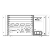
adept technology MV User Manual (404 pages)
Brand:
adept technology
| Category:
Controller
| Size: 5.59 MB
Table of Contents
Table of Contents
10
Introduction
26
How to Use this Manual
27
How to Install and Configure the Adept Controller
27
Related Manuals
27
Other Adept Product Manuals
28
Standard Manuals
28
Developer's Manuals
29
Optional
29
What's New in this Version
29
Warnings, Cautions, and Notes
30
Safety
31
Reading and Training for Users and Operators
31
Computer Controlled Robots and Motion Devices
32
Manually Controlled Robots and Motion Devices
32
Other Computer-Controlled Devices
32
Safety Features on the Compact Interface Panel (CIP)
32
System Safeguards
32
Inappropriate Uses of the Adept Controller
33
Program Security
33
Voltage Interruptions
33
Standards Compliance
34
How Can I Get Help
35
Overview
36
Introduction
37
Adept MV-10 Controller
37
Adept MV-5 Controller
37
The Adept Compact Controller
38
Graphical User Interface and Text-Based User Interface
40
Graphical User Interface Options
40
Text-Based Options
40
AWC System Processor (68040 or 68060)
41
Optional Boards
41
Adept Graphics Board (VGB)
41
System Input/Output Board (SIO)
41
Adept VME Enhanced Joint Interface Board (EJI)
42
Adeptforce VME Board (VFI)
42
Adeptmotion Interface Boards (MI3/MI6)
42
Adeptvision Interface Board (EVI)
42
Auxiliary Processor (AWC with 68060 CPU)
43
Digital Input/Output Board (DIO)
43
Optional Equipment
44
Adeptwindows
44
Compact Interface Panel (CIP)
44
Manual Control pendant (MCP)
44
Color Monitor
45
Extended Keyboard
45
Third-Party Terminals for Text-Based User Interface Controllers
45
Product Descriptions
46
Adeptforce VME
46
Adeptmotion VME
46
Adeptvision
46
Installation of Adept Controllers
48
Shipping, Storage, Unpacking, and Inspection
50
Before Unpacking
50
Repacking for Relocation
50
Shipping and Storage
50
Upon Unpacking
50
Controller ID Label
51
Facility Requirements
51
Voltage Interruptions
52
Enclosure and Disconnect Requirements
52
Installing the MV-5 and MV-10 Controllers
54
AC Power Requirements
54
Facility Overvoltage Protection
54
Power Entry Module
55
The CIP System Power Switch
55
Connecting AC Power Cord
56
Fuse Information (MV-5 and MV-10)
56
System Grounding Information
56
Cooling Fan
57
Fan and Filter Information (MV-5 and MV-10)
57
Procedure to Remove Fuse Holder
57
Filter Inspection and Cleaning
58
Compact Controller Installation
58
Adept MV-4 Insert Overview
58
Removing and Installing Boards
60
Requirements for Installing Boards on the Backplane
60
VME Bus Slot Ordering
60
Upper Backplane Jumper Plugs (P1)
61
VME Bus Address Settings
61
Installing Boards
63
Lower Backplane Jumper Plugs (P2) and Third-Party Boards
63
Removing Boards
63
Installing a Monitor and Keyboard
65
Installation Procedure
65
Connecting Non-Adept Peripherals to the VGB Board
66
Using Adeptwindowspc
67
Chapter 3 Installing an ASCII Terminal (User Supplied)
67
Recommended Terminal for Systems Without a VGB or Adeptwindowspc
67
Contacting WYSE
67
Customer-Supplied Serial Interface Cable
68
Installation Procedure
68
Installing a Stand-Alone Controller in a Rack or Panel
68
Space Around the Chassis
69
Rack Mounting
69
Panel Mounting
69
Installing a Robot Controller in a Rack or Panel
70
Space Around the Chassis
70
Rack Mounting
71
Panel Mounting
71
MV-5 and MV-10 Controller Technical Specifications
73
MV-4 Insert Technical Specifications
73
The Adeptwindows Controller Board
74
AWC Board Connectors and Indicators
75
AWC Board
76
Processors
76
Compact Flash
77
Eeprom
77
AWC Board Specifications
78
Configuring an AWC Module
79
Factory Default Settings
79
DIP-Switch Settings
80
Adeptwindows PC Graphical User Interface
81
VGB Graphical User Interface
81
ASCII Terminal
82
AUTO Boot
82
CPU Board Number Assignment
82
System Controller Jumper Settings
82
Ethernet Connections
83
AWC Module Serial I/O Ports
83
Serial Port 1 (RS-232/TERM)
83
RS-422/485 Connector
84
Serial Port 2 (RS-232)
84
Terminal Mode (ASCII Terminal) Interface
84
Used with a VGB Interface
84
LED Status Indicators on the AWC
86
The Controller Interface Panel
88
Introduction
90
Emergency Stop Switch
90
Panel Switches and Indicators
90
High Power On/Off Switch/Lamp
91
Manual/Automatic Mode Switch
91
MCP Connector
91
System Power Switch
91
AWC Interface (JAWC)
92
NET Switch
92
Side Connectors
92
User Connector (JUSER)
92
Aux (Jext)
93
Back Panel Connectors
93
Cib (Jslv)
93
Devicenet (JDVC)
93
Digital I/O Connections
93
Jcom)
93
Manual Mode Safety Package (MMSP)
93
Rs232 (Jcom)
93
Installation of the Controller Interface Panel (CIP)
94
Location of the CIP
95
Connecting the CIP to the AWC
95
Connecting the MCP to the CIP
97
MCP Cradle
97
MCP Requirements
98
The MCP Bypass Plug
98
Connecting Customer-Supplied Safety and Power Control Equipment
99
Equipment to the CIP
99
To the CIP
99
Emergency Stop Circuit
104
JSIO E-Stop Circuitry
105
Muted Safety Gate E-Stop Circuitry
105
Remote Sensing of CIP, MCP, and User Emergency Stop Push But- Ton Switches
105
Remote Sensing of CIP, MCP, and User Emergency Stop Push Button Switches
105
Remote Manual Mode Control
106
Chapter 5 Remote High Power Control
107
Remote High Power On/Off Lamp
108
Connecting the System Power Switch to the CIP
108
Manual Mode Safety Package (MMSP) Connector
109
Remote User Panel Connections
109
Remote MCP Connections
109
Remote E-Stop Circuit
109
Remote Enable Switch Connections
110
Connecting User-Supplied Serial Communications Equipment
111
RS-232 (JCOM) Connector
111
Connecting User-Supplied Digital I/O Equipment
112
JSIO Connector
112
REACT Input Signals 1001 to 1012
114
Fast Input Signals 1001 to 1004
114
Output Signals
115
Digital I/O Connector Ordering Details (Third-Party Sources)
117
AMP Part Numbers for 50-Pin Male D-Sub
118
Thomas and Betts Part Numbers for 50-Pin Male D-Sub
118
Screw-Terminal Field-Wiring Adapter Blocks
118
Phoenix Contact Inc
118
Weidmüller
119
Extended Digital I/O Signals
120
Extended I/O Inputs
120
Extended I/O Outputs
123
Extended I/O Outputs Diagnostic Signal for Thermal Overload
123
Testing Extended I/O Outputs
123
Extended I/O Output Power Supply Current Selection
124
Optional DIO Cables
126
Labeling Cables
126
Input and Output Cable Wiring Information
126
Adept Graphics Board (VGB)
132
Introduction
133
Connections and Indicators
134
DIP Switch Settings
135
VME Bus Address
135
Monitor Video Interface
136
Keyboard Interface
137
Pointer Interface (Mouse, Trackball, or Touchscreen)
138
VGB Board Specifications
138
Adeptvision Enhanced Vision Interface (EVI) Board
140
Introduction
141
Connections and Indicators
142
VME Bus Address and Configuration
143
EVI Motherboard DIP Switch Setting
143
Acquisition Switch Setting Mode
144
Settings for Normal RS-170 Cameras
145
Settings for Pulnix TM-1001 Cameras
145
Camera Compatibility
146
High-Resolution Cameras
146
Standard RS-170 Cameras
146
Installing Video Bus Coupler
147
Camera Cables
148
Four-Camera Breakout Cable for RS-170 Cameras
148
10-Meter Camera Extension Cables
149
Custom Pulnix TM-1001 Four-Camera Breakout Cable
149
Custom Pulnix TM-1001 D-Sub to BNC Adapter Cable
151
Installing Camera Cables
152
Connecting the Cables to the RS-170 Standard Camera
152
Connecting the Cables to the Pulnix TM-1001 Camera
153
Camera Cable Pin and Signal Information
156
EVI Board Specifications
166
System Input/Output Board (SIO)
168
Introduction
169
Connections and Indicators
170
Mass Storage
171
Floppy Drive
171
Hard Drive
171
Serial I/O Connectors
171
SIO Board Specifications
173
Adeptmotion Interface Board (MI3/MI6)
174
Introduction
175
Connections and Indicators
176
VME Bus Address
177
Jumper Settings and Resistor Configuration on MI3/MI6
178
Connecting to User Equipment
178
MI3/MI6 Board Specifications
178
Enhanced Joint Interface(EJI)
180
Introduction
181
Connections and Indicators
182
VME Bus Address
183
Address Settings for EJI Boards
183
Address Settings for Multiple Servo Boards
183
Belt Encoder Interface
185
EJI Board Specifications
187
Adeptforce VME Board (VFI)
188
Introduction
189
Connections and Indicators
189
VME Bus Address
190
VFI Board Specifications
191
Digital Input/Output Board (DIO)
192
Introduction
193
Connections and Indicators
194
Inputs
195
Outputs
196
Testing Outputs and Fuses
196
Output Power Supply Current Selection
197
Output Power Supply Voltage Jumpers
197
Typical DIO Wiring
199
Optional DIO Cables
201
Input and Output Cable Wiring Information
201
Labeling Cables
201
Additional DIO Boards
206
Setting the Board Address
206
Labeling Sets of Cables
207
DIO Board Specifications
208
Maintenance
210
Introduction
211
Fan Filter Inspection and Cleaning MV-5/MV-10
212
Spare Parts List MV-5/MV-10
213
Changing the Lamp on the High Power Indicator
214
Dimension Drawings
218
Adept MV-5 and MV-10 Stand-Alone Controller Dimensions
219
Adept MV-5 and MV-10 Robot Controller Dimensions
220
The Adept Compact Controller Dimensions
221
MCP Cradle Dimensions
222
Compact Interface Panel Dimensions
223
Position Latch and Vision Trigger
224
External Input for Position Latch and Vision Trigger
225
Position Latch
225
Hardware Interconnection of Boards on an Adept Controller
226
Combined Vision Trigger and Position Latch ("Vision in the Loop")
227
Vision Trigger
227
Additional Standards Compliance Information
228
Sources for Standards
229
IEC Test Information
230
Electromagnetic Compatibility Testing Results
231
Color Coding of Indicator Lights
232
Color Code Used by Adept for Operator Indicators
232
Color Code Used by Adept for Service Indicators
233
Using the Manual Control pendant (MCP)
234
Manual Control pendant Basics
236
Connecting the MCP
237
MCP Layout
238
Soft Buttons
239
Data Entry Buttons
240
Function Buttons
240
Background Mode
241
Emergency Stop from the MCP
241
Mode Control and Joint/Axis Control Buttons
241
Speed Bars and Slow Button
241
MCP Predefined Functions
242
Introduction
242
Predefined Function Buttons
242
The Edit Function
242
The Display Function
245
The Clear Error Function
246
The CMD Function
247
Prog Set Function
248
Moving a Robot or Motion Device with the MCP
250
Introduction
250
Mode Control Buttons
250
COMP/PWR Button
251
Emergency Stop Button
251
MAN/HALT Button
251
DIS PWR Button
252
Joint/Axis Control Buttons
252
Run/Hold
252
STEP Button
252
In Comp Mode
253
In World, Tool, and Joint Mode
253
Slow Button
253
Speed Bars
253
Robot States
254
System Messages
262
Introduction
263
Alphabetical Listing
263
Numerical List
360
Advertisement
adept technology MV User Manual (262 pages)
Brand:
adept technology
| Category:
Controller
| Size: 1.99 MB
Table of Contents
Table of Contents
9
List of Figures
17
Introduction
23
How to Use this Manual
24
Follow These Steps to Install and Configure the Adept MV Controller
24
Related Manuals
24
Standard Manuals
24
Optional V + Developer's Manuals
25
Other Adept Product Manuals
25
Safety
26
Reading and Training for Users and Operators
26
System Safeguards
27
Computer-Controlled Robots and Motion Devices
27
Manually-Controlled Robots and Motion Devices
27
Other Computer-Controlled Devices
27
Safety Features on External VME Front Panel (VFP)
27
Program Security
28
Overspeed Protection
28
Voltage Interruptions
28
Inappropriate Uses of the Adept MV Controller
28
Warnings, Cautions, and Notes
26
Standards Compliance
29
How Can I Get Help
30
Within the Continental United States
30
Application Questions
30
Service Calls
30
Training Information
30
Within Europe
31
Outside Continental United States or Europe
31
Adept World Wide Web Site
31
Adept Bulletin Board Service
31
Overview
33
2.1 Introduction
33
Controller Models
34
Adept MV-5 Controller
34
Adept MV-10 Controller
34
Figure 2-1. Adept MV-5 and MV-10 Controllers
35
Adept MV-8 Controller
36
Adept MV-19 Controller
36
Introduction
34
A-Series and S-Series Controller Options
36
Adept A-Series Option
36
Adept S-Series Option
37
Standard Modules
37
System Processor (030 or 040)
37
030 Module
37
System Input/Output Module (SIO)
37
Optional Modules
38
Adept Graphics Module (VGB)
38
Adeptvision VME Interface Module (VIS)
38
Adeptmotion Interface Modules (MI3/MI6)
38
Figure 2-2. Adept MV Controller Configuration
39
Adept VME Joint Interface Module (VJI)
40
Adeptforce VME Module (VFI)
40
Digital Input/Output Module (DIO)
40
Auxiliary Processor
40
Optional Equipment
41
External Front Panel (VFP-1 or VFP-3)
41
Manual Control pendant (MCP)
41
Adeptnet
41
A-Series Color Monitor
41
A-Series Extended Keyboard
41
Third-Party Terminals for an S-Series Controller
42
Product Descriptions
42
Adeptvision VME
42
Adeptmotion VME
42
Adeptforce VME
42
Installation for MV-5 and MV-10 Controllers
43
Controller ID Label
44
Shipping, Storage, Unpacking and Inspection
44
Shipping and Storage
44
Before Unpacking
44
Upon Unpacking
44
Repacking for Relocation
44
Facility Requirements
45
Voltage Interruptions
45
Table 3-1. Operating Environment Requirements
45
Connecting AC Power (MV-5 and MV-10)
46
AC Power Requirements
46
Facility Overvoltage Protection
46
Table 3-2. Adept MV Controller Power Requirements
46
Power Entry Module
47
Function of VFP System Power Switch with MV-5 and MV-10 Controllers
47
Figure 3-1. MV-5/MV-10 Power Entry Module
47
Remote System Power Option
47
Connecting AC Power Cord
49
Figure 3-3. Installation of User-Supplied External Contactor Using VFP-3
49
Fuse Information (MV-8 and MV-19)
50
Table 3-3. Power Cord Specifications
50
Fuse Information (MV-5 and MV-10)
50
System Grounding Information
50
Fan and Filter Information
51
Figure 3-4. MV-5/MV-10 Fuse Holder
51
Removing and Installing Modules
52
Lower Backplane Jumper Plugs (P2) and Third-Party Modules
53
Figure 3-5. Adept MV-5 Upper Backplane (P1) Jumper Plugs
54
Figure 3-6. Adept MV-10 Upper Backplane (P1) Jumper Plugs
54
Removing Modules
55
Figure 3-7. Connecting the A-Series Monitor and Keyboard
56
Installing the A-Series Monitor and Keyboard
56
Table 3-5. Monitor Compatibility Specifications
57
Installing Non-Adept Peripherals in an A-Series System
57
Installing a Terminal in an S-Series System
58
3.10 Installing a Stand-Alone Controller in a Rack or Panel
59
Figure 3-8. Rack Mounting for MV-5/MV-10 Stand-Alone Controller
59
Panel Mounting
60
Installing a Robot Controller in a Rack or Panel
61
Figure 3-10. Installing Mounting Brackets on MV-5 and MV-10 Robot Controllers
62
3.12 MV-5 and MV-10 Controller Technical Specifications
63
Table 3-6. Technical Specifications for MV Controller
63
Installation for MV-8 and MV-19 Controllers
65
Shipping, Storage, Unpacking and Inspection
66
Shipping and Storage
66
Before Unpacking
66
Upon Unpacking
66
Repacking for Relocation
66
Controller ID Label
66
Table 4-1. Operating Environment Requirements
67
Facility Requirements
67
Voltage Interruptions
67
AC Power Requirements
68
Facility Overvoltage Protection
68
Table 4-2. Adept MV Controller Power Requirements
68
Connecting AC Power
68
Power Entry Module
69
Connecting AC Power Cord
69
Table 4-3. Power Cord Specifications
69
System Grounding Information
70
Changing Voltage Settings (MV-8 and MV-19)
70
Table 4-4. Voltage Selection Jumper Settings
70
Figure 4-2. Adept MV Controller with Back Panel Open
71
Table 4-5. Fuse Ratings
72
Fuse Information (MV-8 and MV-19)
72
Fan and Filter Information
73
Cooling Fan
73
Filter Inspection and Cleaning
73
Removing and Installing Modules
74
Vmebus Address Settings
74
Backplane Jumper Plugs
74
Figure 4-4. Adept MV-8 Backplane Jumper Plugs
75
Removing Modules
76
Installing Modules
76
Installing a Terminal in an S-Series System
76
Installing the A-Series Monitor and Keyboard
76
Installing in a Rack or Panel Mount
77
Space Around the Chassis
77
Panel Mounting
77
Rack Mounting
77
Figure 4-6. Installing Mounting Brackets
78
4.11 MV-8 and MV-19 Controller Technical Specifications
79
Table 4-6. Technical Specifications for MV-8/19 Controllers
79
030 Processor Module
81
Connections and Indicators
82
Introduction
82
Serial I/O Connections, 030 Module
83
RS-422/485 Connector (on 030 Module)
83
Table 5-1. RS-422/485 Connector Pin Assignments
83
RS-232/Term Connector (on 030 Module)
84
Nal)
84
Table 5-2. RS-232/Term Connector Pin Assignments
84
Used in an A-Series System
84
Used in an S-Series System
84
Table 5-3. Pin Assignments for 9-Pin to 25-Pin (DCE) Cable
85
Typical Cable Connections
85
Typical Cable Connections, 9-Pin to 25-Pin (DCE)
85
Recommended Connections, 9-Pin to 25-Pin (Wyse WY-60 Termi- Nal)
86
Typical Cable Connections, 9-Pin to 25-Pin (DTE)
86
Typical Cable Connections, 9-Pin to 9-Pin (AT-Compatible)
87
DTE, DCE, or AT-Style
88
Vmebus Address
89
Memory
89
030 Jumper Settings
90
030 Processor Module Specifications
91
Use as an Auxiliary Processor
91
040 Processor Module
93
Introduction
94
Connections and Indicators
94
Serial I/O Connections, 040 Module
95
Connector (on 040 Module)
95
RS-232/Term Connector (on 040 Module)
96
Used in an A-Series System
96
Used in an S-Series System
96
Table 6-2. RS-232/Term Connector Pin Assignments (on 040 Module)
97
Connections from 040 RS-232 to Wyse Terminal
98
Memory
98
Vmebus Address
99
040 Jumper Settings
99
Figure 6-3. Switch and Jumper Locations on the 040 Module
100
Use as an Auxiliary Processor
101
Processor Module Specifications
101
System Input/Output Module (Sio)
103
Introduction
104
Connections and Indicators
104
DIP Switch Settings
105
Mass Storage
105
Floppy Drive
105
Hard Drive
105
System Configuration Information
105
Serial I/O Connectors
106
Digital I/O Connector
107
Input Signals
107
Fast Input Signals 1001 to 1003
107
REACT Input Signals 1001 to 1012
107
Table 7-3. DIO Input Specifications (SIO Module)
108
Output Signals
109
Typical Digital Input Wiring
110
Typical Digital Output Wiring
111
Digital I/O Connector Pinouts
112
Digital I/O Connector Ordering Details (Third-Party Sources)
113
AMP Part Numbers for 50-Pin Male D-Sub
113
Thomas and Betts Part Numbers for 50-Pin Male D-Sub
114
Screw-Terminal Field-Wiring Adaptor Blocks
114
Emergency Stop Circuit
115
External E-Stop Input
115
Passive E-Stop Output
115
Figure 7-5. E-Stop Diagram with VFP and MCP
116
Table 7-6. Terminal Assignment of the Terminal Block on the Back of the VFP
117
External Front Panel (VFP-1)
118
Controls and Indicators
118
Installing the External Front Panel (VFP)
119
Figure 7-7. External VME Front Panel and MCP Installation
120
Manual Control pendant (MCP)
121
Connecting the MCP to the VFP
121
MCP Cradle
121
7.10 User-Supplied External Front Panel
122
Construction of Cable from SIO to VFP
122
MCP Connector
122
Front Panel/Mcp Connector and Cable
123
7.11 SIO Module Specifications
124
Adept Graphics Module (Vgb)
125
Connections and Indicators
126
DIP Switch Settings
127
Introduction
126
Vmebus Address
127
Monitor Video Interface
128
Pointer Interface
129
Keyboard Interface
129
VGB Module Specifications
130
Adeptvision Vme Module (Vis)
131
Introduction
132
Connections and Indicators
132
Vmebus Address and Configuration
133
Camera Compatibility
134
Installing Video Bus Coupling
135
Camera Breakout Cables
135
Two-Camera Breakout Cable
135
Four-Camera Breakout Cable
136
10-Meter Adept MV Camera Cables
136
Installing Camera Cables
137
Camera Cable Pin and Signal Information
138
Table 9-4. Breakout Cable Strobe and Power Connector Pin Assignments
139
Figure 9-6. Pin Locations for Camera Cable Connector (12-Pin Hirose Male)
140
Table 9-6. Two-Camera Breakout Cable Pin Assignments
141
Table 9-7. Four-Camera Breakout Cable Pin Assignments (Sorted by Destination)
142
Table 9-8. Four-Camera Breakout Cable Pin Assignments (Sorted by Origin)
144
VIS Module Specifications
146
10 Adeptmotion Interface Module (Mi6/Mi3)
147
10.1 Introduction
148
10.2 Connections and Indicators
148
10.3 Vmebus Address
149
10.4 Jumper Settings and Resistor Configuration on MI3/MI6
149
10.5 Connecting to User Equipment
150
MI3/MI6 Module Specifications
151
11 Adept Joint Interface Module(Vji)
153
11.1 Introduction
154
11.2 Connections and Indicators
154
11.3 Vmebus Address
155
Address Settings for VJI Modules
155
Address Settings for Multiple Servo Boards
155
11.4 Belt Encoder Interface
156
Figure 11-2. VJI Belt Encoder Typical Input Circuity
157
11.5 VJI Module Specifications
158
12 Adeptforce Vme Module (Vfi)
159
12.1 Introduction
160
12.2 Connections and Indicators
160
12.3 Vmebus Address
161
12.4 VFI Module Specifications
162
13 Digital Input/Output Module (Dio)
163
13.1 Introduction
164
13.2 Connections and Indicators
164
13.3 Inputs
164
13.4 Outputs
165
Testing Outputs and Fuses
166
Output Power Supply Voltage Jumpers
166
Output Power Supply Current Selection
167
Typical DIO Wiring
168
Figure 13-2. Typical Digital Output Setup
169
13.6 Optional DIO Cables
170
Labeling Cables
170
Input and Output Cable Wiring Information
170
Table 13-4. DIO P1 Input Cable Pin Assignments
171
Table 13-5. DIO P2 Input Cable Pin Assignments
172
Table 13-6. DIO P3 Output Cable Pin Assignments
173
Table 13-7. DIO P4 Output Cable Pin Assignments
174
13.7 Additional DIO Modules
175
Setting the Module Address
175
Labeling Sets of Cables
175
Figure 13-3. Switch and Jumper Locations on DIO PC Board
176
13.8 DIO Module Specifications
177
14 Maintenance
179
14.1 Introduction
180
Fan Filter Inspection and Cleaning
180
Fan Filter Inspection and Cleaning MV-5/MV-10
180
14.4 VFP Lamp Test
181
Spare Parts List
181
Spare Parts List MV-5/MV-10
182
Dimension Drawings
183
Dimensions for Adept MV-5 and MV-10 Stand-Alone Controllers
184
A.2 Dimensions for Adept MV-5 and MV-10 Robot Controllers
185
A.3 Dimensions for Adept MV-8 Controller
186
A.4 Dimensions for Adept MV-19 Controller
187
A.5 Mounting Bracket Dimensions
188
A.6 External Front Panel (VFP-1) Dimensions
189
A.7 MCP Cradle Dimensions
190
B Position Latch and Vision Trigger. . . . . . . . . . . . . . . . . . . . .169
192
B.1 External Input for Position Latch and Vision Trigger
192
Combined Vision Trigger and Position Latch ("Vision in the Loop")
193
Additional Standards Compliance Information
195
C.1 Sources for Standards
196
C.2 IEC Test Information
197
Electromagnetic Compatibility Testing Results
198
C.4 Color-Coding of Indicator Lights
199
Color-Code Used by Adept for Operator-Indicators
199
Color-Code Used by Adept for Service-Indicators
200
adept technology MV Instruction Handbook Manual (154 pages)
Controller Interface
Brand:
adept technology
| Category:
Controller
| Size: 4.03 MB
Table of Contents
Table of Contents
4
Safety
14
Introduction
16
Figure 1-1 Adeptmodules
16
Figure 1-2 Adept MV Controller Interface
16
Definition of Manipulating Industrial Robot
17
How to Use this Manual
17
Notes, Cautions, and Warnings
17
Figure 1-3 Adeptmodules Joint Motions
17
Precautions and Required Safeguards
18
Adeptmodules Static Forces
18
Safety Barriers
18
Additional Safety Information
19
Table 1-4 Sources for International Standards and Directives
19
Intended Use of the Adeptmodules
20
Adeptmodules Modifications
21
Acceptable Modifications
21
Unacceptable Modifications
21
Endangerment through Additional Equipment
21
Working Areas
22
Qualification of Personnel
22
Transport
23
1.10 Safety Equipment for Operators
23
1.11 Protection against Unauthorized Operation
23
1.12 Operating Modes of Adeptmodules
23
Automatic Mode
23
Manual Mode
24
1.13 Safety Aspects While Performing Maintenance
24
1.14 What to Do in an Emergency Situation
24
1.15 How to Get Help
24
In Europe
24
Europe/Germany
24
France
25
Italy
25
In the United States
25
Application Questions
25
Applications Internet E-Mail Address
25
Service Calls
25
Training Information
25
Outside Continental United States or Europe
26
Installation
28
Environmental and Facility Requirements for Adeptmodules
30
Compressed Air for the Adeptmodules
30
Facility Ambient Air Quality for Adeptmodules
30
Mounting Surface
30
Mounting Surface Specifications
30
Environmental and Facility Requirements for Controller
30
Table 2-1 Operating Environment Requirements
30
Environmental and Facility Requirements for Power Chassis
31
Before Unpacking the Adept Equipment
31
Transport and Storage
31
Unpacking and Inspecting the Adept Equipment
31
Repackaging for Relocation
32
Adeptmodules Installation
32
2.9 Installation of the Adept MV Controller and the Adept PA-4 Power Chassis
33
Installation of the Adept MV Controller and the Adept PA-4 Power Chassis
33
Joining an Adept PA-4 Power Chassis to an Adept MV Controller
33
Figure 2-1 Joining the Power Chassis and Controller at the Top
33
Figure 2-2 Joining the Power Chassis and Controller at the Bottom
34
Joining at the Bottom
34
Joining at the Top
34
Installation in a Rack or Panel Mount
35
Panel Mounting
35
Rack Mounting
35
Space Around the Chassis
35
Figure 2-3 Installing Mounting Brackets on an Adept MV Controller
36
Figure 2-4 Installing Mounting Brackets on an Adept PA-4 Power Chassis
37
2.10 Installing the A-Series Monitor and Keyboard
38
Installation Procedure
38
Figure 2-5 Connecting the A-Series Monitor and Keyboard
38
2.11 Installing a Terminal in an S-Series System
39
Recommended Terminal for S-Series Systems
39
Installation Procedure
39
Installing Adeptwindows PC
39
2.13 Installing the External Front Panel
40
Controls and Indicators
40
Figure 2-6 External Front Panel (VFP)
40
Installing the External Front Panel (VFP)
41
Figure 2-7 External Front Panel (VFP) Installation
41
2.14 Installing Non-Adept Peripherals in an A-Series System
42
Third-Party Monitor Compatibility
42
Third-Party Keyboard Compatibility
42
Third-Party Pointing Device Compatibility
42
Table 2-2 Monitor Compatibility Specifications
42
Installing the Signal Interface Box (SIB)
43
Connections and Indicators
43
Figure 2-8 Signal Interface Box
43
Figure 2-9 Signal Interface Box LED Indicators
44
Table 2-3 LED Status and Indications
44
Installation of the Signal Interface Box (SIB)
45
Space Around the Signal Interface Box
45
Typical Digital Output Wiring
45
Table 2-4 User Output/Brake Release Connector Pin Assignments
45
Figure 2-10 User Output Wiring Diagram
46
Changing User Output Voltage Setting
47
Table 2-5 User Outputs Specifications
47
Installing a Brake Release Button
48
Adeptmodules Instruction Handbook, Volume 1: Adept MV Controller Interface, Rev. a
48
Figure 2-11 Configuring 12 or 24 Volts
48
Figure 2-12 Brake Release Button
48
2.16 Signal Interconnection Installation
49
Figure 2-13 Adept System Cable Installation
49
System Cable Connections
49
Connecting the Adeptmodules to the Power Chassis
50
System Cable Lengths
50
Table 2-6 System Cable Lengths
50
Installing Signal Cables: Adeptmodules to Signal Interface Box
51
Installing Signal Cables: MV Controller to Power Chassis
51
Table 2-7 EJI Specifications
51
Figure 2-14 Adeptmodules-To-EJI Cable Installation
52
Figure 2-15 Connecting the PA-4 Power Chassis to the MV Controller
53
Installing Signal Cables: MV Controller to Signal Interface Box
53
Connecting the MCP to the VFP
54
Figure 2-16 MCP Connection
54
MCP Cradle
54
2.17 Grounding Information
55
Adept MV Controller Grounding
55
Adept PA-4 Power Chassis Grounding
55
2.18 Connecting to AC Power
56
Figure 2-17 Adeptmodules System Grounding Diagram
56
AC Power Requirements
57
Connecting AC Power to the MV-5/10 Controller
57
Power Entry Module
57
Table 2-8 Adept MV Controller Power Requirements
57
Connecting AC Power Cord
58
Figure 2-18 Adept MV Controller Power Entry Module
58
Table 2-9 Adept MV Controller Power Cord Specifications
58
Connecting AC Power to the Adept PA-4 Power Chassis
59
Table 2-10 Adept PA-4 Power Chassis Power Requirements
59
Connecting the Power Chassis AC Power Cord
60
Table 2-11 AC Power Cord Specifications for Power Chassis
60
Figure 2-19 Typical 380-415 VAC Connection
61
Figure 2-20 Typical 3-Phase 200-240 VAC Connection
61
Typical AC Power Installation Diagrams
61
Changing Voltage Setting for Power Chassis
62
Figure 2-21 Insulating Blue Wire in Power Cord
62
Connecting AC Power to the Signal Interface Box
63
Figure 2-22 Changing Voltage in Power Chassis
63
Power Entry Module
64
Table 2-12 Signal Interface Box AC Power Requirements
64
2.19 Additional Power Chassis Information
65
B+ Amplifier Module Overview
65
Connectors and Indicators
65
Power Chassis Circuit Breaker and Fuse Information
66
Chassis and Amplifier Module Fuses
66
Chassis Circuit Breaker
66
Removing and Installing Amplifier Modules
66
Removing Amplifier Modules
66
Installing Amplifier Modules
67
2.20 Installing End-Effectors on Adeptmodules
67
Connecting Compressed Air Supply to the Adeptmodules (Optional)
67
Preparation for Safe and Effective Use of the Robot
68
Overview of Safety System
70
Introduction
70
Operating in Manual Mode
70
User-Supplied E-Stop Switches
70
Terminal Block on External Front Panel
71
Table 3-1 Terminal Assignment of the Terminal Block on the Back of the VFP
71
External E-Stop Input
72
Passive E-Stop Output
72
Digital Inputs and Outputs of the System Input/Output (SIO) Module
73
Input Signals
73
Table 3-2 DIO Input Specifications (SIO Module)
73
Output Signals
74
Table 3-3 DIO Output Specifications (SIO Module)
74
Digital I/O Connector Pinouts
75
Table 3-4 Digital I/O Connector Pin Assignments on SIO Module
75
Figure 3-1 Digital I/O Connector Pin Locations on SIO Module
76
Figure 3-2 E-Stop Diagram with VFP and MCP
77
Typical Emergency Stop Circuitry
77
Figure 3-3 E-Stop Circuitry with Additional Safety Equipment
78
Commissioning the System
80
Introduction
82
Physical Connections
82
Operating Modes
82
Manual Operating Mode
82
Automatic Operating Mode
83
Using the Brake Release Button
83
Brake Release Button
83
Brakes
84
Description of the Manual Control pendant (MCP)
84
How to Hold the MCP
84
Figure 4-1 Holding the MCP
85
Description of Buttons on the MCP
86
Figure 4-2 MCP Layout
86
Mode Control and Joint/Axis Control Buttons
86
Speed Bars
86
How to Stop Adeptmodules in Manual Mode
87
Prior to Starting the Adeptmodules
87
Adept Utility Disk
87
Software Configuration
87
Overview of Adeptmodules Quick Setup
88
SPEC Data
88
Bringing up an Adeptmodules System
89
Overview of System Bring up
89
Overview of System Bring-Up
89
Single Robot with One Motion Board (EJI)
89
How to Start Adeptmodules
91
Enable High Power with the MCP
91
In Automatic Mode
91
Calibration of the Adeptmodules with the MCP
92
Calibration Parameters
92
In Manual Mode
92
Changing Calibration Direction
93
Figure 4-3 Command (CMD) Function Button
93
Moving the Adeptmodules with the MCP
95
Figure 4-4 Mode Control Buttons
95
Joint/Axis Control Buttons
95
MAN/HALT Button for Selecting Joint State
95
Figure 4-5 Speed Bars
96
Selecting Joint State and Moving the Adeptmodules
96
Speed Bars
96
Figure 4-6 Joint State
97
Selecting and Moving Joint 1 (X)
97
Selecting and Moving Joint 2 (Y)
97
Selecting and Moving Joint 2 (Y)
98
Selecting and Moving Joint 3 (Z)
98
Adeptmodules Instruction Handbook, Volume 1: Adept MV Controller Interface, Rev. a
98
Selecting and Moving Joint 4 (Theta)
98
Limiting Joint Travel
98
Maintenance
100
Introduction
102
Modules Lubrication
102
Lubrication Schedule
102
Lubrication Grease
103
Grease Adapter Nozzle
103
Lubrication Procedures
103
Table 5-1 Lubrication Schedule
103
Connectors and Pins
104
Connector Pins and Inserter/Extractor Tools
104
Maintenance and Inspection of Air Filters
106
Adept MV-19 Controller Fan Filter Inspection and Cleaning
106
Adept MV-5/MV-10 Controller Fan Filter Inspection and Cleaning
106
Adept PA-4 Amplifier Chassis Fan Filter Inspection and Cleaning
106
Check Lamps on VFP
107
Technical Specification
108
Dimensions
110
Adept Linear Modules Dimensions
110
Adept MV-5 and MV-10 Controllers Dimensions
110
Figure 6-1 Adept MV-5 and MV-10 Dimensions
110
Adept MV-19 Controller Dimensions
111
Figure 6-2 Adept MV-19 Dimensions
111
Adept PA-4 Power Chassis Dimensions
112
Figure 6-3 Adept PA-4 Power Chassis Dimensions
112
Dimensions of the Signal Interface Box
113
Figure 6-4 Adeptmodules Signal Interface Box
113
Dimensions of the External Front Panel
114
Figure 6-5 Adept External Front Panel Dimensions
114
Dimensions of the Mounting Brackets
115
Figure 6-6 Adept MV-5/10 and PA-4 with Mounting Brackets Installed
115
MCP Cradle Dimensions
116
Figure 6-7 MCP Cradle Dimensions
116
Adept MV Controller Power Consumption
117
Adept PA-4 Power Chassis Power Consumption
117
Table 6-1 Adep T MV Controller Power Requirments
117
Table 6-2 Power Consumption for PA-4 Power Chassis (Four-Axis Configuration)
117
Advertisement
Advertisement
Related Products
adept technology MV-19
adept technology MV-5
adept technology MV-10
adept technology MV-4
adept technology MotionBlox-10
adept technology MP6
adept technology MB-60R
adept technology Adept RS-232/TERM
adept technology Adept RS-422/485
adept technology Adept XSYS
adept technology Categories
Robotics
Controller
Network Router
Thermostat
Control Unit
More adept technology Manuals
Login
Sign In
OR
Sign in with Facebook
Sign in with Google
Upload manual
Upload from disk
Upload from URL