Sign In
Upload
Manuals
Brands
adept technology Manuals
Controller
Adept RS-232/TERM
adept technology Adept RS-232/TERM Manuals
Manuals and User Guides for adept technology Adept RS-232/TERM. We have
1
adept technology Adept RS-232/TERM manual available for free PDF download: User Manual
adept technology Adept RS-232/TERM User Manual (156 pages)
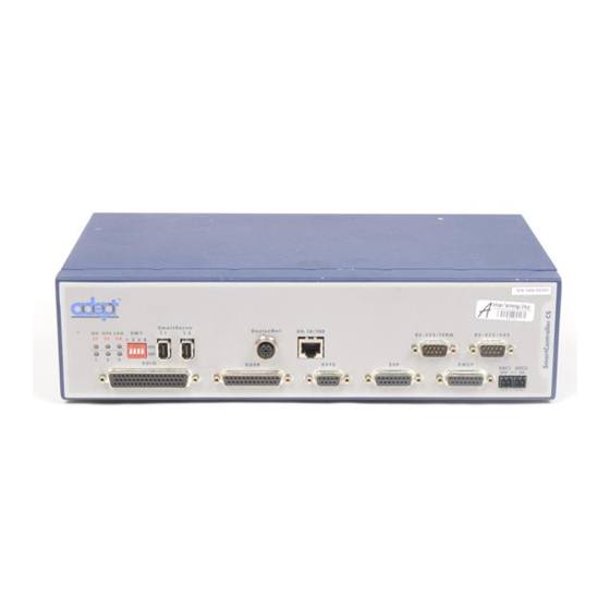
Nortech Systems SmartController User's Guide
Brand:
adept technology
| Category:
Controller
| Size: 3.85 MB
Table of Contents
Table of Contents
5
1 Introduction
15
Product Description
15
Adept Smartcontroller CS
15
Adept Smartcontroller CX
15
Sdio Expansion Module
15
How Can I Get Help
16
Related Manuals
16
Adept Document Library
16
Table 1-1. Related Manuals
16
Warnings, Cautions, and Notes
17
Safety
17
Reading and Training for Users and Operators
17
System Safeguards
18
Computer Controlled Robots and Motion Devices
18
Safety Features on the Front Panel
18
Manually Controlled Robots and Motion Devices
19
Other Computer-Controlled Devices
19
Program Security
19
Inappropriate Uses of the Adept Smartcontroller
20
Standards Compliance
20
CAT-3 Version of Smartcontroller
21
Identification
21
Functionality Changes
21
High Power Indication on XDIO Connector
21
MCP Enable Switch Not Functional in Auto Mode
21
E-Stop Circuit
21
Operational Change in Smartmodule Systems
22
2 Smartcontroller Installation
23
Controller Installation
23
Before Unpacking
23
Upon Unpacking
23
Table 2-1. Environmental Specifications
23
Repacking for Relocation
24
Space Around the Chassis
24
Mounting the Smartcontroller
24
Figure 2-1. Rack Mounting the Smartcontroller
25
Rack Mounting the Smartcontroller
25
Figure 2-2. Panel Mounting the Smartcontroller
26
Panel Mounting the Smartcontroller
26
Figure 2-3. Table Mounting the Smartcontroller
27
Stacking Components
28
Compactflash Memory Card
28
Figure 2-4. Stack Mounting the Smartcontroller and Sdio
28
Installing Compactflash
29
Figure 2-5. Compactflash Memory Card Compartment
29
Connecting Power
30
24VDC Power Specifications
30
Table 2-2. Specifications for 24VDC User-Supplied Power Supply
30
24VDC Power Cabling
31
Daisy-Chaining Power
31
Figure 2-6. User Supplied Power Cable
31
Grounding
31
Figure 2-7. Chassis Grounding Point
32
Installing 24VDC Connectors
32
IEEE 1394 Cable Specifications
33
Figure 2-8. 24V Connectors
33
System Cable Installation
34
Figure 2-9. System Cable Diagram
34
3 Smartcontroller Operation
37
Smartcontroller CS Connectors and Indicators
37
Figure 3-1. Smartcontroller CS
37
Table 3-1. Smartcontroller Leds
37
Table 3-2. LED Status Indicators
38
Smartcontroller CX Connectors and Indicators
40
Figure 3-2. Smartcontroller CX
40
Front Panel
41
Figure 3-3. Front Panel
41
Configuring the Controller
42
Factory Default Settings
42
DIP-Switch Settings
42
Adeptwindows PC Graphical User Interface
43
ASCII Terminal
43
Table 3-3. SW1 Settings
43
AUTO Boot
44
Smartcontroller Serial I/O Connectors
44
RS-232 Connectors
44
Table 3-4. RS-232 Connector Pin Assignments
44
RS-422/485 Connector
45
Table 3-5. Serial Connectors and
45
Table 3-6. RS-422/485 Connector Pin Assignments
45
Installing the User Interface
46
Graphical Interface Using Adeptwindows
46
Text Interface Using a PC with Hyperterminal Software
47
Installation Procedure
47
Text Interface Using a Terminal
48
Installation Procedure
48
Recommended Terminal for Text-Based Systems
48
Connecting Customer-Supplied Safety and Power Control Equipment
49
Connecting Equipment to the System
49
Table 3-7. Contacts Provided by the XUSR Connector
49
Table 3-8. Contacts Provided by the XFP Connector
50
Table 3-9. Remote MCP Connections on the XMCP Connector
51
Figure 3-4. CAT-3 E-Stop Circuit on XUSR and XFP Connectors
52
Figure 3-5. Non-CAT-3 E-Stop Circuit on XUSR and XFP Connectors
53
Emergency Stop Circuits
54
Figure 3-6. Front Panel Schematic
54
Line E-Stop Input
55
Muted Safety Gate E-Stop Circuitry
55
User E-Stop Indication - Remote Sensing of E-Stop
55
Remote Manual Mode
56
User Manual/Auto Indication
56
User High Power on Indication
56
Remote High Power On/Off Control
57
High Power On/Off Lamp
57
Remote Front Panel Usage
57
Remote MCP Usage
58
Connecting Customer-Supplied Digital I/O Equipment
58
XDIO Connector
59
Input Signals
59
Table 3-10. DIO Input Circuit Specifications (XDIO Connector)
59
Fast Input Signals 1001 to 1004
60
Figure 3-7. Digital Input Wiring Examples (XDIO Connector)
60
REACT Input Signals 1001 to 1012
60
Output Signals
61
Table 3-11. DIO Output Specifications (XDIO Connector)
61
Figure 3-8. Digital Output Wiring for XDIO Connector
62
Table 3-12. XDIO Digital I/O Connector Pin Assignments
63
Digital I/O Connector Ordering Details (Third-Party Sources)
64
AMP Part Numbers for 50-Pin Male D-Sub
64
Thomas and Betts Part Numbers for 50-Pin Male D-Sub
64
Screw-Terminal Field-Wiring Adapter Blocks
64
Phoenix Contact Inc
64
Weidmüller
64
Belt Encoder Interface on Smartcontroller CX
65
Table 3-13. Belt Encoder Connector Pin Assignments
65
Figure 3-9. Belt Encoder Typical Input Circuit
66
4 Adeptvision Savi Option
67
Introduction
67
Savi Board Features
67
Savi Board System Requirements and Restrictions
67
Pixel Format
68
Adeptvision Savi Inspection System Limitations
68
Camera Compatibility
68
Guidelines for Cameras
68
Cameras Supported
69
Downloading Camera Information
69
High Resolution Cameras
69
Standard Resolution Cameras
69
Camera Cables
70
Two-Camera Breakout Cable for RS-170 Cameras
70
Figure 4-1. Two-Camera Breakout Cable for RS-170 Cameras
70
Four-Camera Breakout Cable for RS-170 Cameras
71
10-Meter Camera Extension Cables
71
Figure 4-2. Four-Camera Breakout Cable for RS-170 Cameras
71
Installing Camera Cables
72
Connecting the Cables to the RS-170 Standard Camera
72
Figure 4-3. Camera Cable Installation Drawing (RS-170)
73
Camera Cable Pin and Signal Information
74
Table 4-1. Breakout Cable Camera Connector Pin Assignments (RS-170)
75
Table 4-2. Standard Breakout Cable Strobe and Power Connector Pin Assignments
76
Figure 4-4. Pin Locations for Camera Cable Connector (12-Pin Hirose Male)
77
Table 4-3. Adept 10-Meter Camera Cable Pin Assignments
77
Table 4-4. Two-Camera Breakout Cable Pin Assignments
78
Table 4-5. Four-Camera Breakout Cable Pin Assignments
79
Table 4-6. Four-Camera Breakout Cable Pin Assignments
81
Savi Board Specifications
83
Table 4-7. Technical Specifications
83
5 Smartcontroller Maintenance
85
Changing the Lamp in the High Power Indicator
85
Figure 5-1. Lamp Body Contact Alignment
86
6 Technical Specifications
87
Smartcontroller Dimensions
87
Figure 6-1. Smartcontroller Dimensions
87
Sdio Dimensions
88
Figure 6-2. Sdio Dimensions
88
Adept Front Panel Dimensions
89
Figure 6-3. Adept Front Panel Dimensions
89
Figure 6-4. Adept Front Panel Back View
90
Adept MCP Dimensions
91
Figure 6-5. MCP Dimensions
91
Figure 6-6. MCP Cradle Dimensions
92
Sdio Module
93
A.1 Mounting the Sdio
93
Figure A-1. Sdio Module
93
Figure A-2. Rack Mounting the Sdio
94
Rack Mounting the Sdio
94
Figure A-3. Panel Mounting the Sdio
95
Panel Mounting the Sdio
95
Stack Mounting
96
A.2 Installing the Sdio
96
Figure A-4. Table Mounting the Sdio
96
A.3 Configuring a Single Sdio
97
Default Sdio I/O Configuration
97
Table A-1. Default I/O Configuration for Sdio
97
Assigning Sdio Signal Blocks
98
Modifying the Default Sdio Configuration
98
Assigning I/O Signal Numbers
99
Sdio Signal Mapping Example 1
101
Sdio Signal Mapping Example 2
101
A.4 Using Multiple Sdio Modules
102
Figure A-5. Using Multiple Sdio Modules
102
Configuring a System with an Sdio and a RIO
103
A.5 Sdio Module Connectors and Indicators
103
Figure A-6. Sdio
103
A.6 Sdio Digital I/O Signals
104
Sdio Inputs
104
Table A-2. Sdio Input Specifications
104
Figure A-7. Typical Sdio Input Wiring
105
Sdio Leds
106
Sdio Outputs
106
Testing Sdio Outputs
106
Sdio Output Power Supply Current Selection
107
Table A-3. Sdio Chassis Leds
107
Table A-4. Sdio Output Circuit Specifications
108
Figure A-8. Typical Sdio Output Wiring
109
Labeling Cables
110
Optional DIO Cables
110
Input and Output Cable Wiring Information
111
Table A-5. X3 Input Cable Pin Assignments
111
Table A-6. X4 Input Cable Pin Assignments
112
Table A-7. X1 Output Cable Pin Assignments
113
Table A-8. X2 Output Cable Pin Assignments
114
Adept Devicenet
115
Devicenet Specifications
115
Volume 1
115
Volume 2
115
Limitations of the Adept Devicenet Scanner
116
Adept Supplied Devicenet Hardware
116
Table B-1. Devicenet Signal to Pin Locations
116
Connecting Devicenet Hardware to the Adept Devicenet Scanner
117
Devicenet Physical Layer and Media
117
Figure B-1. Trunklines and Droplines Made of Thick and Thin Cable
118
Table B-2. Features of a Devicenet Network
119
Table B-3. Devicenet Data Rates Relative to Cable Type and Length
119
Figure B-2. Devicenet Thick Cable
120
Figure B-3. Devicenet Thin Cable
120
Devicenet Connectors
121
Figure B-4. Devicenet Connectors
121
Termination of the Devicenet Network
121
Table B-4. Devicenet Connector Styles
121
Figure B-5. Example of a Terminating Resistor Installation on a Devicenet Bus
122
Power Capabilities of a Devicenet Cable System
122
Power Supply and the Devicenet Bus
122
Table B-5. Maximum Current on a Dropline Relative to Its Length
123
Figure B-6. Devicenet Connector Pinouts
124
Using the Manual Control pendant (MCP)
125
C.1 Manual Control pendant Basics
125
MCP Enable Switch Function on CAT-3 Smartcontroller
125
Mcp III
125
126
126
3-Position Enable Switch
126
Figure C-1. 3-Position Enable Switch on MCP-4
126
MCP-4 Compatibility
127
Table C-1. MCP-4 Compatibility Guidelines
127
Figure C-2. Holding the MCP
128
Figure C-3. Cradling the MCP
128
Connecting the MCP
129
Figure C-4. MCP Layout
130
Function Buttons
130
MCP Layout
130
Soft Buttons
130
Data Entry Buttons
131
Emergency Stop from the MCP
131
Figure C-5. Data Entry Buttons
131
Mode Control and Joint/Axis Control Buttons
131
Speed Bars and Slow Button
131
In Automatic Mode
132
In Manual Mode
132
Re-Enabling Power after Enable Switch Released
132
Background Mode
133
C.2 MCP Predefined Functions
133
Figure C-6. MCP Predefined Function Buttons
133
Figure C-7. EDIT Function Button
134
The Edit Function
134
Figure C-8. DISPLAY Function Button
135
The Display Function
135
Figure C-9. CLEAR ERROR Function Button
137
The Clear Error Function
137
The CMD Function
137
Figure C-10. Command (CMD) Function Button
138
Figure C-11. Program Set Function Button
139
Prog Set Function
139
Introduction
133
Predefined Function Buttons
133
C.3 Moving a Robot or Motion Device with the MCP
140
Introduction
140
Mode Control Buttons
140
Figure C-12. Mode Control Buttons
140
COMP/PWR Button
141
Emergency Stop Switch
141
MAN/HALT Button
141
DIS PWR Button
142
Run/Hold
142
Joint/Axis Control Buttons
142
STEP Button
142
Speed Bars
142
In World, Tool, and Joint Mode
142
In Comp Mode
143
Slow Button
143
Robot States
143
Figure C-13. Speed Bars
143
World State
143
Figure C-14. WORLD State (Four-Axis SCARA)
144
Tool State
144
Figure C-15. TOOL State (Four-Axis SCARA)
145
Figure C-16. TOOL State (Six-Axis Robot)
146
Figure C-17. JOINT State (Four-Axis SCARA)
147
Joint State
147
Figure C-18. JOINT State (Six-Axis Robot)
148
Free State
148
Controlling more than One Robot
149
Figure C-19. FREE State (Four-Axis SCARA)
149
Robots with Fewer than Six Joints
150
Robots with more than Six Joints
150
Index
151
Advertisement
Advertisement
Related Products
adept technology Adept RS-422/485
adept technology Adept XSYS
adept technology Adept XUSR
adept technology R Series
adept technology R-H
adept technology R-M
adept technology R-S
adept technology R-Hz
adept technology R-Mz
adept technology Adept Cobra i600
adept technology Categories
Robotics
Controller
Control Unit
Network Router
Thermostat
More adept technology Manuals
Login
Sign In
OR
Sign in with Facebook
Sign in with Google
Upload manual
Upload from disk
Upload from URL