Table of Contents
Advertisement
Quick Links
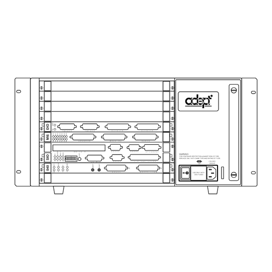
Adept MV Controller
ON
OK
1
2 3 4
5
6 7 8
®
WARNING:
FOR CONTINUED PROTECTION AGAINST RISK OF FIRE,
REPLACE ONLY WITH SAME TYPE AND RATING OF FUSE.
~100-240V
50/60HZ
5AT
USE ONLY WITH
250V FUSES
User's Guide
040
SIO
VGB
VIS
VJI
DIO
FAIL
PASS
SF
STP
ES
HPE
1
OK
OK
1
2
A
SCR
2
ESTOP
3
4
3
ACC V
V
V
5
6
B
C
4
SCSI
I
I
I
N
D
D
P
D
VME
E
E
U
O
O
T
S
B
B
U
U
D
S
S
R
I
RESET
V
E
A
M
I
O
N
N
P
U
I
F
T
T
P
S
O
/
ABORT
R
M
C
AMPLIFIER
P
RESET
SIGNAL
1
2
3
4
R
O
R
R
S
U
S
S
2
T
4
2
3
P
2
3
2
U
2
2
T
BELT
S
ENCODER
P
#1
R
O
S
I
I
2
N
T
/
3
C
O
2
E
R
A
R
M
2
O
S
E
4
U
2
R
V
T
3
E
A
P
2
T
S
1
U
/
H
/
0
T
T
S
0
E
S
E
R
T
m
R
N
R
A
M
E
O
T
B
ARM
E
#2
KEYBOARD
SIGNAL
S
WARNING:
FOR CONTINUED PROTECTION
AGAINST RISK OF FIRE,
REPLACE ONLY WITH SAME
TYPE AND RATING OF FUSE.
5AT
~100-240V
50/60HZ
®
Advertisement
Chapters
Table of Contents

Related Manuals for adept technology MV


Summary of Contents for adept technology MV
- Page 1 Adept MV Controller User’s Guide FAIL PASS ESTOP ACC V SCSI RESET ABORT AMPLIFIER RESET SIGNAL BELT ENCODER ® KEYBOARD SIGNAL ® WARNING: FOR CONTINUED PROTECTION AGAINST RISK OF FIRE, REPLACE ONLY WITH SAME TYPE AND RATING OF FUSE. WARNING:...
- Page 3 Adept MV Controller User’s Guide FAIL PASS ESTOP ACC V SCSI RESET ABORT AMPLIFIER SIGNAL RESET BELT ENCODER ® KEYBOARD SIGNAL ® WARNING: FOR CONTINUED PROTECTION AGAINST RISK OF FIRE, REPLACE ONLY WITH SAME TYPE AND RATING OF FUSE. WARNING:...
- Page 4 The information contained herein is the property of Adept Technology, Inc. and shall not be repro- duced in whole or in part without prior written approval of Adept Technology, Inc. The informa- tion herein is subject to change without notice and should not be construed as a commitment by Adept Technology, Inc.
- Page 5 2. The Controller must be used in accordance with instructions specified in the Adept MV Controller Instruction Handbook. 3. The Controller must incorporate only those MV Plug-in Modules listed in Table 1 or Table 2 attached. If Plug-in Modules listed in Table 2 are installed, the user must verify conformance to the EMC Directive after installation.
- Page 6 English Declaration of Conformity as defined in Machinery Directive 89/392/EEC, Appendix IIB We herewith declare that the machine as delivered by us complies with the relevant and fundamental safety and health requirements defined in the EC Directive, Appendix 1. Deutsch Konformitätserklärung im Sinne der EG-Maschinenrichtlinie 89-392/EWG, Anhang II B Hiermit erklären wir, daß...
- Page 7 PCA, VME Joint Interface (VJI III) 15600-00090 Camera, CCD Table 2 Plug-in Modules and Accessories that may be installed in MV-5, MV-8, MV-10, and MV-19 Controllers but must first be tested in the final system configuration to assure full compliance. Part Number...
-
Page 9: Table Of Contents
1.1 How to Use This Manual ......Follow These Steps to Install and Configure the Adept MV Controller Related Manuals . - Page 10 ......Function of VFP System Power Switch with MV-5 and MV-10 Controllers Remote System Power Option .
- Page 11 ......3.12 MV-5 and MV-10 Controller Technical Specifications ..
- Page 12 ......4.11 MV-8 and MV-19 Controller Technical Specifications ..
- Page 13 ......Passive E-Stop Output ......Adept MV Controller User’s Guide, Rev C...
- Page 14 ......10.2 Connections and Indicators ..... . Adept MV Controller User’s Guide, Rev C...
- Page 15 14.1 Introduction ......Adept MV Controller User’s Guide, Rev C xiii...
- Page 16 ......A.1 Dimensions for Adept MV-5 and MV-10 Stand-Alone Controllers ..
- Page 17 ..... . . Figure 3-5. Adept MV-5 Upper Backplane (P1) Jumper Plugs ...
- Page 18 Table Of Contents Figure 3-9. Panel Mounting for MV-5/MV-10 Stand-Alone Controller ..Figure 3-10. Installing Mounting Brackets on MV-5 and MV-10 Robot Controllers . . . Figure 4-1. Power Entry Module ......
- Page 19 ....Table 5-3. Pin Assignments for 9-Pin to 25-Pin (DCE) Cable ... . Adept MV Controller User’s Guide, Rev C xvii...
- Page 20 ..... . . Table 11-1. VMEbus Address Switch Settings for VJI Module ... . xviii Adept MV Controller User’s Guide, Rev C...
- Page 21 ....Table C-4. Service Indicator Color-Code ..... Adept MV Controller User’s Guide, Rev C...
-
Page 23: Introduction
1.1 How to Use This Manual ......Follow These Steps to Install and Configure the Adept MV Controller Related Manuals . -
Page 24: How To Use This Manual
1. Read Chapter 1 to learn about Safety and Customer Service issues and Chapter 2 to get an overview of the Adept MV controller and its components. 2. Read Chapter 3 or 4 to learn the steps in installing the controller. It covers AC power installation, fuse information, installing and removing modules, connecting monitors and keyboards, and installing in a rack or panel mount. -
Page 25: Other Adept Product Manuals
(known as monitor commands). Language Reference Guide A complete description of the keywords in the basic V language system. AdeptVision Reference Guide Descriptions of the additional V keywords available with the AdeptVision VME option. Adept MV Controller User’s Guide, Rev C... -
Page 26: Warnings, Cautions, And Notes
There are several warnings in this manual that say only skilled or instructed persons should attempt certain procedures. These are defined as: Adept MV Controller User’s Guide, Rev C... -
Page 27: System Safeguards
Make sure that safeguards are in place to prevent personnel from entering the workcell when a program is running. Adept Technology highly recommends the use of additional safety features such as light curtains, safety gates, or safety floor mats to prevent entry to the workcell while HIGH is enabled. -
Page 28: Program Security
Inappropriate Uses of the Adept MV Controller The Adept MV controller is intended for use as a component sub-assembly of a complete industrial automation system. The Adept MV controller sub-assembly must be installed inside a suitable enclosure. Installation and usage must comply with all safety instructions and warnings in this manual. -
Page 29: Standards Compliance
Standards Compliance Standards Compliance The Adept MV controller is intended for use with other equipment and is considered a sub-assembly rather than a complete piece of equipment on its own. The Adept MV controller meets the requirements of EN 60204, IEC 1131-2, IEC 73, and IEC 447 safety standards. -
Page 30: How Can I Get Help
Chapter 1 - Introduction How Can I Get Help? Within the Continental United States Adept Technology maintains a Customer Service Center at its headquarters in San Jose, CA. The phone numbers are: Service Calls (800) 232-3378 5:00am - 5:00pm PST (24 hour emergency coverage, 7 days a week) -
Page 31: Within Europe
BBS.) The BBS number is (203) 264-5590. The first time you call you will be able to set up an account right from the BBS. If you have any questions, call (203) 264-0564 and ask about the BBS. Adept MV Controller User’s Guide, Rev C... -
Page 33: Overview
......AdeptForce VME ......Adept MV Controller User’s Guide, Rev C... -
Page 34: Introduction
Controller Models Adept MV-5 Controller The Adept MV-5 controller is a 5-slot chassis that is available in either a stand-alone or robot configuration; see Figure 2-1. The stand-alone version stands horizontally and can be mounted in a standard 19-inch equipment rack. The robot version stands vertically and can be joined to an Adept PA-4 power chassis, and the joined units can be mounted in a standard 19-inch equipment rack. -
Page 35: Figure 2-1. Adept Mv-5 And Mv-10 Controllers
2 3 4 6 7 8 ~100-240V 50/60HZ USE ONLY WITH 250V FUSES Adept MV Robot Controller Adept MV Stand-Alone Controller (example shown: MV-10) (example shown: MV-5) Figure 2-1. Adept MV-5 and MV-10 Controllers Adept MV Controller User’s Guide, Rev C... -
Page 36: Adept Mv-8 Controller
The Adept MV-19 controller is a 19-slot chassis. The required system processor (030 or 040) and SIO modules occupy 3 slots, as in the Adept MV-8, leaving 16 slots open for optional modules. The Adept MV-19 is designed to fit in a standard 19-inch rack-mount equipment cabinet. -
Page 37: Adept S-Series Option
System Input/Output Module (SIO) The System Input/Output module (SIO) is also required for all Adept MV controllers. The SIO is a two-slot 6U VME module that handles the basic I/O for an Adept MV controller. The SIO module features include: •... -
Page 38: Optional Modules
Up to four MI6 modules can be installed in an Adept MV-19 controller, as long as there is sufficient processing power. The MI3/MI6 module can be used with both A-Series and S-Series Adept MV controllers. -
Page 39: Figure 2-2. Adept Mv Controller Configuration
030 or 040 - 3 modules max per controller, same specs as main Processor system processor AdeptMotion MI6 - 6 axes motor control per module, up to 4 modules in MV-10/19 Interface MI3 - 3 axes motor control per module Digital... -
Page 40: Adept Vme Joint Interface Module (Vji)
32 input channels and 32 output channels. It is a 6U VME slave module and all inputs and outputs are optically isolated. Up to 8 DIO modules can be installed in an Adept MV-19 controller, depending on slot availability. The total I/O capacity (including the channels on the SIO module) of a controller with 8 DIO modules is 268 input channels and 264 output channels. -
Page 41: Optional Equipment
The external Front Panel (VFP) is a separate control panel that can be added to any Adept MV controller system. There are two types of VFPs: the VFP-1 and the VFP-3. The VFP-1 is used with all Adept systems that do not include the Manual Mode Safety Package (MMSP) option. -
Page 42: Third-Party Terminals For An S-Series Controller
Chapter 2 - Overview Third-Party Terminals for an S-Series Controller For S-Series Adept MV controllers, the user must supply a terminal to interface to the controller. The terminal must be a Wyse model 60 or 75 with an keyboard, or a ANSI compatible terminal and keyboard. -
Page 43: Installation For Mv-5 And Mv-10 Controllers
......3.4 Connecting AC Power (MV-5 and MV-10) .... -
Page 44: Shipping, Storage, Unpacking And Inspection
Chapter 3 - Installation for MV-5 and MV-10 Controllers Shipping, Storage, Unpacking and Inspection Shipping and Storage This equipment must be shipped and stored in a temperature controlled environment, within the range -25°C to +55°C. The recommended humidity range is 5 to 90%, non-condensing. -
Page 45: Facility Requirements
Facility Requirements Facility Requirements The Adept MV controller is intended for use with other equipment and is considered a sub-assembly rather than a complete piece of equipment on its own. The Adept MV controller meets the requirements of EN 60204-1, IEC 1131-2, IEC 73, and IEC 447 safety standards. -
Page 46: Connecting Ac Power (Mv-5 And Mv-10)
The maximum interruption time (operating voltage below specification) tolerated by the controller is 16 milliseconds. If the Adept MV Controller is used with an Adept robot, see the robot user’s guide or instruction handbook for additional power requirements. Facility Overvoltage Protection The user must protect the controller from excessive overvoltages and voltage spikes. -
Page 47: Power Entry Module
The External Front Panels, VFP-1 and VFP-3, include support for controlling system power on the MV-5 and MV-10 controllers. If you want to use this feature, you must provide an AC contactor (with 12V or 24V coil, either AC or DC coil, limited to less than 500 mA.) See the drawings on the next two pages for connection details. - Page 48 Chapter 3 - Installation for MV-5 and MV-10 Controllers FAIL PASS ESTOP ACC V SCSI RESET Pins 1 and 2 of terminal ABORT AMPLIFIER block on VFP-1 RESET SIGNAL External Front Panel (VFP-1) BELT ENCODER SYSTEM HIGH POWER LAMP MANUAL...
-
Page 49: Connecting Ac Power Cord
AC power source, using the color code below. You must provide a suitable plug or other facility connection in accordance with all applicable local and national codes. See the next section for important information on system grounding. Adept MV Controller User’s Guide, Rev C... -
Page 50: Fuse Information (Mv-8 And Mv-19)
The detachable three-wire power cord is used for connection to both the power source and protective ground. The protective ground conductor (colored green/yellow) in the power cord is internally connected to the exposed metal parts of the MV Controller. To ensure electrical-shock protection, the protective ground conductor must be connected to a properly grounded power source. -
Page 51: Fan And Filter Information
Fan and Filter Information Table 3-4. MV-5 and MV-10 Fuse Ratings Fuse Rating Type F1 – AC Line fuse at Power 5 AT/250 V IEC 127-style Entry module 5 x 20 mm F2 – AC Line fuse at Power 5 AT/250 V... -
Page 52: Removing And Installing Modules
• module in adjacent slot is 2-slots wide (for example, SIO) but only connects to the P1 connector in one slot. On a typical controller, jumper plugs are factory-installed in slot 3 (or slot 4 in an MV-10 with an AdeptNet board installed). You do not have to do anything with jumper plugs unless you change the position of the modules in the controller, then see the following information. -
Page 53: Lower Backplane Jumper Plugs (P2) And Third-Party Modules
Adept modules. These include some safety-critical signals, including 24 V signals. On the MV-5 and MV-10, jumpers are provided next to each P2 connector. If a non-Adept (third-party) module is installed in a slot, and that module uses the P2 (lower) connector, the P2 user-signal jumpers for that slot must be removed. -
Page 54: Figure 3-5. Adept Mv-5 Upper Backplane (P1) Jumper Plugs
In a typical MV-10 system, jumper plugs are factory-installed at slot 3. In an MV-10 system with an AdeptNet board installed in slot 2, jumpers must be installed in slot 2 and slot 4. Figure 3-6. Adept MV-10 Upper Backplane (P1) Jumper Plugs... -
Page 55: Removing Modules
CAUTION: Do not attempt to install or remove any boards without first turning off the power to the Adept MV Controller and all related external power supplies. Failure to observe this caution could cause damage to your equipment. -
Page 56: Figure 3-7. Connecting The A-Series Monitor And Keyboard
Installation Procedure An A-Series Adept MV controller can be configured with a color monitor and an extended keyboard with built-in trackball. Both of these devices connect to the VGB module. See the Operating System User’s Guide for details on using the keyboard and trackball. -
Page 57: Table 3-5. Monitor Compatibility Specifications
75 ohm ±5% at 100 kHz Third-Party Keyboard Compatibility The Adept MV controller can interface to keyboards that are “AT” compatible and use a standard DIN 5 connector. See Chapter 8 for the pin assignments on the connector. Third-Party Pointing Device Compatibility The Adept MV controller can interface to any mouse, trackball, or other pointing device that uses the Microsoft mouse serial protocol (1200 bps). -
Page 58: Installing A Terminal In An S-Series System
Wyse-75. Recommended Terminal for S-Series Systems The recommended terminal for use with the Adept MV controller is the Wyse WY-60. You must also specify that you require the Wyse ANSI/VT100 style keyboard (Wyse p/n 900127-02 or 900128-02). -
Page 59: Figure 3-8. Rack Mounting For Mv-5/Mv-10 Stand-Alone Controller
See Chapter 14 for details on cleaning the filter. Rack Mounting To rack mount the Adept MV-5 or MV-10 Stand-Alone controller in a standard 19-inch equipment rack, you must use the mounting brackets from the accessories kit. See Figure 3-8 for instructions. See Appendix A for dimensions. -
Page 60: Panel Mounting
Chapter 3 - Installation for MV-5 and MV-10 Controllers Panel Mounting To panel mount the Adept MV-5 or MV-10 Stand-Alone controller, you must use the mounting brackets and screws from the accessories kit. See Figure 3-9 for instructions. Side View of MV-5 or MV-10... -
Page 61: Installing A Robot Controller In A Rack Or Panel
3.11 Installing a Robot Controller in a Rack or Panel An MV-5 or MV-10 Robot controller can be mounted in a rack or panel by using the mounting brackets that are shipped in the accessories kit. The brackets can be attached at the rear of the controller for panel mounting or they can be attached to the front of the controller for rack mounting. -
Page 62: Figure 3-10. Installing Mounting Brackets On Mv-5 And Mv-10 Robot Controllers
M4 x 25mm screw (2 places) (2 places) M4 x 10mm screw M4 x 10mm screw Rack Mount – Flush Rack Mount – Set-Back Figure 3-10. Installing Mounting Brackets on MV-5 and MV-10 Robot Controllers Adept MV Controller User’s Guide, Rev C... -
Page 63: Table 3-6. Technical Specifications For Mv Controller
MV-5 and MV-10 Controller Technical Specifications 3.12 MV-5 and MV-10 Controller Technical Specifications Table 3-6. Technical Specifications for MV Controller MV-5 MV-10 Input Voltage 100-120 and 200-240 VAC, 100-120 and 200-240 VAC, auto ranging auto ranging DC Power Supply (total) - Page 65 ......4.11 MV-8 and MV-19 Controller Technical Specifications ..
-
Page 66: Shipping, Storage, Unpacking And Inspection
Chapter 4 - Installation for MV-8 and MV-19 Controllers Shipping, Storage, Unpacking and Inspection Shipping and Storage This equipment must be shipped and stored in a temperature controlled environment, within the range -25°C to +55°C. The recommended humidity range is 5 to 90%, non-condensing. -
Page 67: Table 4-1. Operating Environment Requirements
Facility Requirements Facility Requirements The Adept MV controller is intended for use with other equipment and is considered a sub-assembly rather than a complete piece of equipment on its own. The Adept MV controller meets the requirements of EN 60204, IEC 1131-2, IEC 73, and IEC 447 safety standards. -
Page 68: Ac Power Requirements
The maximum interruption time (operating voltage below specification) tolerated by the controller is 16 milliseconds. If the Adept MV Controller is used with an Adept robot, see the robot user’s guide for additional power requirements. Facility Overvoltage Protection The user must protect the controller from excessive overvoltages and voltage spikes. -
Page 69: Power Entry Module
Cord length 3 meters ±0.1 m (9 ft. 10 in. ±4 in.) Cord rating 10 amps Number and size of 3 x 1.00 mm conductors Color code line brown neutral blue ground green/yellow Adept MV Controller User’s Guide, Rev C... -
Page 70: System Grounding Information
The detachable three-wire power cord is used for connection to both the power source and protective ground. The protective ground conductor (colored green/yellow) in the power cord is internally connected to the exposed metal parts of the MV Controller. To ensure electrical-shock protection, the protective ground conductor must be connected to a properly grounded power source. -
Page 71: Figure 4-2. Adept Mv Controller With Back Panel Open
9. Connect the AC power cord and the controller is ready to operate. Numbering pattern on jumper block Remove these screws (two on each side) to fold down the back panel. Configuration Jumper Block Figure 4-2. Adept MV Controller with Back Panel Open Adept MV Controller User’s Guide, Rev C... -
Page 72: Table 4-5. Fuse Ratings
Chapter 4 - Installation for MV-8 and MV-19 Controllers Fuse Information (MV-8 and MV-19) The two fuses (F3 and F4) at the power entry module on the front panel are for the incoming AC power lines. There are three fuses (F1, F2, and F5) inside the back section of the chassis, at the left side (looking from the front) near the top (see Figure 4-3). -
Page 73: Fan And Filter Information
Fan and Filter Information Cooling Fan The chassis is cooled by a fan in the lower front section of the chassis. The MV-8 has one fan, the MV-19 has two fans. Air intake is through the lower front of the chassis and the exhaust is out through the top. -
Page 74: Removing And Installing Modules
Chapter 4 - Installation for MV-8 and MV-19 Controllers Removing and Installing Modules The Adept MV controller is shipped from the factory with all the modules specified on the sales order installed in the chassis. Any unused slots are filled with blank covers. You may want to add modules in the future or remove and re-install a module for some reason. -
Page 75: Figure 4-4. Adept Mv-8 Backplane Jumper Plugs
P1 Backplane for slot 8 Edge Connectors for Adept MV-8 Slot Slot Slot Slot Slot Figure 4-4. Adept MV-8 Backplane Jumper Plugs Jumpers Jumpers Jumpers Jumpers Jumpers for slot 5 for slot 6 for slot 17 for slot 18... -
Page 76: Removing Modules
CAUTION: Do not attempt to install or remove any boards without first turning off the power to the Adept MV Controller and all related external power supplies. Failure to observe this caution could cause damage to your equipment. -
Page 77: Installing In A Rack Or Panel Mount
The Adept MV-8 controller can be joined to an Adept PA-4 power chassis and mounted in a rack. Refer to the documentation that comes with the PA-4 for information. -
Page 78: Figure 4-6. Installing Mounting Brackets
Chapter 4 - Installation for MV-8 and MV-19 Controllers M4 x 25mm screw (2 places) To Install Mounting Brackets: • Remove (and discard) 3 existing countersunk screws from side of chassis at locations shown in drawing. • Place bracket in desired position and secure with indicated M4 screws and washers from accessories kit. -
Page 79: 4.11 Mv-8 And Mv-19 Controller Technical Specifications
MV-8 and MV-19 Controller Technical Specifications 4.11 MV-8 and MV-19 Controller Technical Specifications Table 4-6. Technical Specifications for MV-8/19 Controllers MV-8 MV-19 Input Voltage 100-120/200-240 VAC 100-120/200-240 VAC DC Power Supply (total) 250 W 500 W Power Available on Backplane... -
Page 81: 030 Processor Module
..... . 5.8 030 Processor Module Specifications ....Adept MV Controller User’s Guide, Rev C... -
Page 82: Introduction
4 modules. The 030 is a single-slot 6U VME module that can serve as the main system processor for an Adept MV controller. The CPU for this module is a Motorola 68EC030 microprocessor running at 40 MHz. The module can be configured with 2, 4, or 8 MB of DRAM. -
Page 83: Serial I/O Connections, 030 Module
Table 5-1. RS-422/485 Connector Pin Assignments Signal Signal RTS+ RTS– RXD+ RXD– TXD+ TXD– CTS+ CTS– Ground Pin 5 Pin 9 Pin 6 Pin 1 Figure 5-1. RS-422/485 Female Connector Pin Locations (on 030 module) Adept MV Controller User’s Guide, Rev C... -
Page 84: Rs-232/Term Connector (On 030 Module)
Output CTS (Clear to Send) Input DTR (DTE Ready) Output not used SG (Signal Ground) Pin 1 Pin 6 Pin 9 Pin 5 Figure 5-2. RS-232/Term Male Connector Pin Locations (on 030 module) Adept MV Controller User’s Guide, Rev C... -
Page 85: Typical Cable Connections
For many applications, including connecting to a serial printer or terminal, 25-pin or 9-pin adapter cables may be required. The next few tables give some examples. Because the Adept MV controller uses the same connector and compatible pinouts as the IBM PC-AT computer, suitable cables may be available from your local computer dealer. -
Page 86: Typical Cable Connections, 9-Pin To 25-Pin (Dte)
Signal ground Recommended Connections, 9-pin to 25-pin (Wyse WY-60 Terminal) Adept recommends the use of a Wyse WY-60 terminal on S-Series Adept MV controllers. The previous table shows a full “7-wire” DTE interface with hardware handshaking (flow control). The following simplified connections will work with most terminals using DTE pinouts, such as the Wyse WY-60 terminal. -
Page 87: Typical Cable Connections, 9-Pin To 9-Pin (At-Compatible)
Adept controller. Pin 1 is not connected inside the Adept MV Controller. No connection is required, but if you are using a standard cable that connects to this pin no damage should occur. -
Page 88: Dte, Dce, Or At-Style
Table 5-7. Typical 25-pin Null-Modem Adaptor Pinout 25-Pin D (male) 25-Pin D (female) 25-Pin D (male) 25-Pin D (female) Shield Shield 6 & 8 DSR & CD 6 and 8 DSR & CD Ground Ground Adept MV Controller User’s Guide, Rev C... -
Page 89: Memory
VMEbus Address Each processor module in an Adept MV controller must have a unique module address. The address is set on switch SW2 on the 030 PC board. Table 5-8 shows the switch settings for multiple processor modules. See Figure 5-3 for the location of SW2. -
Page 90: 030 Jumper Settings
1994 require JP3. It must be OFF when used with older SIO modules – 30330-00301 or 30330-10351. SCON SCLK 1 2 3 4 5 6 7 8 Adept 030 Board – Component Side Figure 5-3. Switch and Jumper Locations on the 030 Module Adept MV Controller User’s Guide, Rev C... -
Page 91: Use As An Auxiliary Processor
Use as an Auxiliary Processor Use as an Auxiliary Processor Additional 030 System processor modules can be installed in an Adept MV controller and used as auxiliary processors to handle specific functions in an Adept automation system. For example, you can have an auxiliary 030 dedicated to handling processing for the... -
Page 93: 040 Processor Module
..... . 6.8 040 Processor Module Specifications ....Adept MV Controller User’s Guide, Rev C... -
Page 94: Introduction
4 modules. The 040 is a single-slot 6U VME module that can serve as a main or an auxiliary system processor for an Adept MV controller. The CPU for this module is a Motorola 68040 microprocessor running at 25MHz. The module can be ordered with 4 or 8 MB of DRAM (not field upgradeable). -
Page 95: Serial I/O Connections, 040 Module
RXD signals. CAUTION: The RS-422 and RS-232 ports on the 040 both use 25-pin female connectors. Be sure to label each connector and take precautions to avoid connecting to the wrong port. Adept MV Controller User’s Guide, Rev C... -
Page 96: Rs-232/Term Connector (On 040 Module)
040 module using a DIP switch on the SIO module; see section 7.2 for information on that switch. Pin 13 Pin 25 Pin 14 Pin 1 Figure 6-2. RS-232 Connector on 040 Module (25-Pin Female DB-25F , lower connector) Adept MV Controller User’s Guide, Rev C... -
Page 97: Table 6-2. Rs-232/Term Connector Pin Assignments (On 040 Module)
CAUTION: The RS-422 and RS-232 ports on the 040 both use 25-pin female connectors. Be sure to label each connector and take precautions to avoid connecting to the wrong port. Adept MV Controller User’s Guide, Rev C... -
Page 98: Connections From 040 Rs-232 To Wyse Terminal
Chapter 6 - 040 Processor Module Connections from 040 RS-232 to Wyse Terminal Adept recommends the use of a Wyse WY-60 terminal on S-Series Adept MV controllers. The following connections will work with most terminals using DTE pinouts, such as the Wyse WY-60 terminal. -
Page 99: Vmebus Address
VMEbus Address VMEbus Address Each 040 module in an Adept MV controller must have a unique module address. The address is set on Jumper block J22 on the 040 PC board (see Figure 6-3 for location of jumpers). Table 6-4 shows the jumper settings for multiple processor modules. -
Page 100: Figure 6-3. Switch And Jumper Locations On The 040 Module
Chapter 6 - 040 Processor Module SCON Adept 040 Board – Component Side Figure 6-3. Switch and Jumper Locations on the 040 Module Adept MV Controller User’s Guide, Rev C... -
Page 101: Use As An Auxiliary Processor
Use as an Auxiliary Processor Use as an Auxiliary Processor Additional 040 System processor modules can be installed in an Adept MV controller and used as auxiliary processors to handle specific functions in an Adept automation system. For example, you can have an auxiliary 040 dedicated to handling processing for the... -
Page 103: System Input/Output Module (Sio)
....7.11 SIO Module Specifications ..... . . Adept MV Controller User’s Guide, Rev C... -
Page 104: Introduction
Chapter 7 - System Input/Output Module (SIO) Introduction The System Input/Output (SIO) module is a required module in all Adept MV controllers. The 2-slot-wide SIO is a 6U VME slave module that provides the system I/O functions for the controller. It serves as the system interface to mass storage (hard drive and floppy drive), E–Stop circuitry, three user RS-232 serial ports, 20 digital... -
Page 105: Dip Switch Settings
Operating System User’s Guide for information on formatting floppy disks. Hard Drive The 256 MB internal hard drive is located inside the SIO module. (The size of the hard drive is subject to change.) Adept MV Controller User’s Guide, Rev C... -
Page 106: Serial I/O Connectors
TXD (To Device) CTS (Clear to Send) DTR (Data Terminal Ready) not used SG (Signal Ground) Pin 1 Pin 6 Pin 9 Pin 5 Figure 7-1. RS-232 Serial I/O Connector Pin Locations on SIO Module Adept MV Controller User’s Guide, Rev C... -
Page 107: Digital I/O Connector
Extensions License. See the V Language Reference Guide for a description of the INT.EVENT instruction. The last three functions (events, latch, and trigger) can only be obtained using input signals 1001 to 1003. Adept MV Controller User’s Guide, Rev C... -
Page 108: Table 7-3. Dio Input Specifications (Sio Module)
2 ms response time (minimum) for fast inputs 1001 to 1003, depending on program task configuration, when used with V INT.EVENT instruction. Adept MV Controller User’s Guide, Rev C... -
Page 109: Output Signals
SIO module are different than the specifications for the DIO module described in Chapter 13. Specifically, the SIO output current is limited to 100 mA per channel, whereas the DIO output is rated at 400 mA. Adept MV Controller User’s Guide, Rev C... -
Page 110: Typical Digital Input Wiring
Signal 1008 – + – Signal 1009 Example 3 – + – Signal 1010 – + – Signal 1011 – + – Signal 1012 – Figure 7-2. Typical Digital Input Wiring on the SIO Adept MV Controller User’s Guide, Rev C... -
Page 111: Typical Digital Output Wiring
Load Signal 0007 – Load Signal 0008 – EMERGENCY See section later in this chapter STOP for a description of Emergency CONNECTIONS Stop Circuits Figure 7-3. Typical Digital Output Wiring on the SIO Adept MV Controller User’s Guide, Rev C... -
Page 112: Digital I/O Connector Pinouts
1012 return Not used Not used Output 0001+ Output 0001– See next section for information on ordering a compatible third-party connector. Pins 41, 42, 43, and 44, see Figure 7-5 for more information. Adept MV Controller User’s Guide, Rev C... -
Page 113: Digital I/O Connector Ordering Details (Third-Party Sources)
(Alternatives: 66682-9, 66682-2, 66682-4, 66682-6, 66682-8) (Pins also available for other wire sizes, contact AMP) AMP Sales (partial list): USA: 800-522-6752, Canada (416) 475-6222, Germany: (06103) 7090, Japan: (044) 844-8111, France: (1) 34.43.27.20, UK: (0181) 954-2356 Adept MV Controller User’s Guide, Rev C... -
Page 114: Thomas And Betts Part Numbers For 50-Pin Male D-Sub
AD911886 - RD 50 ASJS – “D-Sub to wire transition module, 50 pin female D-Sub with jackscrews.” Weidmüller Sales: USA (800)þ849-9343 or (804)þ794-2877, Australia (047) 354211, Canada (416)þ475-1507, Germany (05231)þ4510, France (1) 34.50.34.50, Japan (035)þ820-5747, Singapore 296-6133, UK (01795) 58099 (Source: Weidmüller USA, Sept. 1994) Adept MV Controller User’s Guide, Rev C... -
Page 115: Emergency Stop Circuit
NOTE: This section applies to systems that do not include the Manual Mode Safety Package (MMSP) option. For systems that do include the MMSP, refer to the AdeptOne-MV/AdeptThree-MV Robot Instruction Handbook for complete information on E-stop circuits. The Emergency Stop (E-Stop) circuit should be used by the customer to include safety devices in the design of a workcell. -
Page 116: Figure 7-5. E-Stop Diagram With Vfp And Mcp
External E-Stop Input E-Stop Signal To user Passive E-Stop Output to backplane equipment (0.8 A at 12 VDC, 0.4 A at 24 VDC, see text) Figure 7-5. E-Stop Diagram with VFP and MCP Adept MV Controller User’s Guide, Rev C... -
Page 117: Table 7-6. Terminal Assignment Of The Terminal Block On The Back Of The Vfp
(contacts are closed in Manual mode) Emergency Stop switch on the external Front Panel (N/C) Emergency Stop switch on the Manual Control Pendant (N/C) Hold-to-Run switch on the Manual Control Pendant (N/O) not used not used Adept MV Controller User’s Guide, Rev C... -
Page 118: External Front Panel (Vfp-1)
The VFP-1 is described in this section. The label on the back of the VFP identifies the type – VFP-1 or VFP-3. The VFP-3 is used with systems that have the MMSP option installed. The VFP-3 is described in the AdeptOne-MV/AdeptThree-MV Robot Instruction Handbook. SYSTEM HIGH POWER... -
Page 119: Installing The External Front Panel (Vfp)
Mount the VFP in the same enclosure as the controller, or in a separate, protected enclosure. See section 3.3 on page 23 (MV-5/10) or section 4.3 on page 45 (MV-8/19) for enclosure requirements. See Figure 7-7 as you follow the procedure below. -
Page 120: Figure 7-7. External Vme Front Panel And Mcp Installation
External Front Panel (VFP) SYSTEM HIGH POWER LAMP MANUAL AUTO POWER ON/OFF TEST EMERGENCY STOP ® PROGRAM PROGRAM PENDANT NETWORK LOCAL RUNNING START Manual Control Pendant Figure 7-7. External VME Front Panel and MCP Installation Adept MV Controller User’s Guide, Rev C... -
Page 121: Manual Control Pendant (Mcp)
E-stop + Hold-to-run + E-stop – Not used –12 V Hold-to-run – AMP 16-pin circular plastic connector, male is on VFP, female is on MCP cable. See next section for information on part numbers. Adept MV Controller User’s Guide, Rev C... -
Page 122: 7.10 User-Supplied External Front Panel
If a user-supplied external front panel is connected to the Adept MV controller, it must be designed to meet, and all equipment used must be compliant with, EN 60204 and all other applicable international and local regulations. -
Page 123: Front Panel/Mcp Connector And Cable
CAUTION: The ±12 V and +24 V supplies listed above must only be used for their intended purposes. The 24 V supply is for the E-stop and system power switch only. The 12 V is to power the MCP and the VFP only. Adept MV Controller User’s Guide, Rev C... -
Page 124: 7.11 Sio Module Specifications
Panel (VFP), excluding +12 V 0.4 A (with lamp test pressed) –12 V not used Width Occupies 2 backplane slots Serial Ports Three RS-232, at 300 – 19,200 bps Specifications subject to change. Adept MV Controller User’s Guide, Rev C... -
Page 125: Adept Graphics Module (Vgb)
......8.7 VGB Module Specifications ..... . . Adept MV Controller User’s Guide, Rev C... -
Page 126: Introduction
Chapter 8 - Adept Graphics Module (VGB) Introduction The Adept Graphics module (VGB) is required for A-Series Adept MV controllers. The VGB is a single-slot 6U VME module that serves as the graphics processor and controls the video output to the color monitor. The VGB has connectors for the monitor, keyboard, and pointing device (mouse, trackball, etc.). -
Page 127: Dip Switch Settings
If you change the settings, you must reboot (turn controller off, then on) before the changes take effect. VMEbus Address The VGB module has a fixed address and should not be modified by the customer. Adept MV Controller User’s Guide, Rev C... -
Page 128: Monitor Video Interface
Red Video Ground Vertical Sync Green Video Ground Not connected Blue Video Ground Pin 5 Pin 10 Pin 15 Pin 11 Pin 6 Pin 1 Figure 8-1. Monitor Connector Pin Locations on VGB Module Adept MV Controller User’s Guide, Rev C... -
Page 129: Keyboard Interface
8.2 for configuration and compatibility. Table 8-4. Pointer Connector Pin Assignments Signal Signal Shield not connected Transmit Data (from pointer) +12 VDC (RTS) Receive Data (to pointer) not connected not connected not connected Signal Ground Adept MV Controller User’s Guide, Rev C... -
Page 130: Vgb Module Specifications
Pointer Input For mouse or trackball, Microsoft serial mouse protocol, 1200 bps For touchscreen, ELO TouchSystems protocol, 1200 bps Keyboard input AT compatible, DIN-5 connector Width Occupies one backplane slot Specifications subject to change. Adept MV Controller User’s Guide, Rev C... -
Page 131: Adeptvision Vme Module (Vis)
....9.9 VIS Module Specifications ..... . . Adept MV Controller User’s Guide, Rev C... -
Page 132: Introduction
Video Bus cable in AdeptVision VME systems. The other end of the cable connects to the VGB module. Camera/Strobe connector – a 44-pin D-sub connector for either the two-camera or four-camera breakout cables. Adept MV Controller User’s Guide, Rev C... -
Page 133: Vmebus Address And Configuration
• B: POS_LATCH 1 and VIS_TRIGGER 1 (recommended for VIS module 1) or... • A: POS_LATCH 2 and VIS_TRIGGER 2 (recommended for VIS module 2) All other switches on SW1, SW3, and SW2 should be set as shown above. Adept MV Controller User’s Guide, Rev C... -
Page 134: Camera Compatibility
500 x 480. More is normally better, if the camera, lens, etc., are good quality. The actual number of pixels does not affect compatibility, because the interface is via the RS-170-standard video-link. For interfacing cameras without external sync, contact Adept Customer Service. Adept MV Controller User’s Guide, Rev C... -
Page 135: Installing Video Bus Coupling
— they do not connect directly to the camera. To connect to the cameras, you must use an additional cable. Adept offers a 10-meter Adept MV camera cable for this purpose. See Tables 9-3 to 9-8 for pin and signal information. -
Page 136: Four-Camera Breakout Cable
Figure 9-4. Four-Camera Breakout Cable 10-Meter Adept MV Camera Cables The 10-meter Adept MV Camera cables have a male Hirose connector on one end and a female Hirose connector on the other end. These cables are intended to go between the breakout cables and the connectors on the cameras. -
Page 137: Installing Camera Cables
User-Supplied 9-pin Male D-Sub Connector KEYBOARD Four-Camera Strobe/Power Breakout Cable Connector User 12VDC Up to Two Power Supply Optional to Drive Strobe Cameras Lamps Figure 9-5. Camera Cable Installation Drawing Adept MV Controller User’s Guide, Rev C... -
Page 138: Camera Cable Pin And Signal Information
This connector will normally be connected to the camera via the optional 10-Meter Adept MV Camera Cable. For special applications, this connector will mate with a Hirose Male Plug HR10A-10P-12P (user supplied) or similar. Adept MV Controller User’s Guide, Rev C... -
Page 139: Table 9-4. Breakout Cable Strobe And Power Connector Pin Assignments
(do not use) Reserved (do not use) Shield (chassis ground) 9-Pin D-Sub female Receptacle Note: this connector will mate with a 9-pin D-Sub male plug (user-supplied). The two-camera breakout cable does not include this connector. Adept MV Controller User’s Guide, Rev C... -
Page 140: Figure 9-6. Pin Locations For Camera Cable Connector (12-Pin Hirose Male)
At each end the shield is clamped to connector body. Brown Gray Black Blue Yellow White Orange (Wire colors Overall may vary.) Braided Shield Figure 9-6. Pin Locations for Camera Cable Connector (12-Pin Hirose Male) Adept MV Controller User’s Guide, Rev C... -
Page 141: Table 9-6. Two-Camera Breakout Cable Pin Assignments
Also note that this cable provides 12V dc (fused 1A max) to the cameras from the Adept controller. The fuse is not user-replaceable. If the total current required by the two cameras exceeds 1A, this cable should not be used. Adept MV Controller User’s Guide, Rev C... -
Page 142: Table 9-7. Four-Camera Breakout Cable Pin Assignments (Sorted By Destination)
Power return Str/Pwr CAM3 +12V power CAM3 Shield(video) CAM3 Video CAM3 Shield(Hd) CAM3 Hd (horizontal drive) CAM3 Vd (vertical drive) CAM3 not connected CAM3 not connected CAM3 not connected CAM3 not connected CAM3 Shield(Vd) Adept MV Controller User’s Guide, Rev C... - Page 143 Strobe 2 Str/Pwr Reserved Str/Pwr Reserved Str/Pwr Reserved Str/Pwr Shield (chassis ground) Note that this cable provides user-supplied 12V dc to the cameras via the Strobe and Power connector, not from the Adept controller. Adept MV Controller User’s Guide, Rev C...
-
Page 144: Table 9-8. Four-Camera Breakout Cable Pin Assignments (Sorted By Origin)
CAM2 Clock CAM1 Clock Str/Pwr Strobe 1 CAM2 Video CAM4 Shield(video) CAM4 Vd (vertical drive) CAM3 Hd (horizontal drive) CAM3 Shield(Hd) CAM3 Shield(Vd) CAM2 Hd (horizontal drive) CAM2 Shield(Hd) CAM2 Shield(Clock) CAM2 Shield(Vd) Adept MV Controller User’s Guide, Rev C... - Page 145 Str/Pwr Strobe 2 Str/Pwr Reserved CAM1 Video CAM2 Shield(video) CAM3 Video Note that this cable provides user-supplied 12V dc to the cameras via the Strobe and Power connector, not from the Adept controller. Adept MV Controller User’s Guide, Rev C...
-
Page 146: Vis Module Specifications
Table 9-9. Technical Specifications Electrical Power Consumption 5 VDC at 5.0 A +12 V at 1.25 A (including 1 amp for cameras) –12 V at 0.1 A Width Occupies 1 backplane slot Specifications subject to change. Adept MV Controller User’s Guide, Rev C... -
Page 147: Adeptmotion Interface Module (Mi6/Mi3)
....10.6 MI3/MI6 Module Specifications ....Adept MV Controller User’s Guide, Rev C... -
Page 148: 10.1 Introduction
Servo connector – a 44 pin D-Sub female connector for the servo cable to interface to the servo signals in the installation. Adept MV Controller User’s Guide, Rev C... -
Page 149: 10.3 Vmebus Address
Table 10-1 shows how to set the address when you have multiple modules in an Adept MV controller. If you purchased the Adept MV controller from Adept with all the motion modules installed, the correct DIP switch settings will have already been set for you by Adept. -
Page 150: 10.5 Connecting To User Equipment
Each connector on the MI3/MI6 has a corresponding cable and MP6 mounting panel. The MP6 panels can be installed on standard DIN mounting rails. See the AdeptMotion VME Developer’s Guide for complete information on the installation and setup of user equipment. Adept MV Controller User’s Guide, Rev C... -
Page 151: Mi3/Mi6 Module Specifications
MV-5: 2 MI6 MV-10: 4 MI6 Number of axes of control 3 axes of control per MI3 module 6 axes of control per MI6 module Width Occupies one backplane slot Specifications subject to change. Adept MV Controller User’s Guide, Rev C... - Page 153 ......11.5 VJI Module Specifications ..... . . Adept MV Controller User’s Guide, Rev C...
-
Page 154: 11.1 Introduction
Belt Encoder connector – a 15 pin D-Sub connector for up to two belt encoders in a conveyor tracking installation. AMPLIFIER SIGNAL Arm Signal connector – the VJI to Robot cable from the Adept robot is installed here. BELT ENCODER SIGNAL Adept MV Controller User’s Guide, Rev C... -
Page 155: 11.3 Vmebus Address
VMEbus address. Check the address settings on all modules to make sure they are all different. If you purchased the Adept MV controller from Adept with all the motion modules installed, the correct DIP switch settings will have already been set for you by Adept. -
Page 156: 11.4 Belt Encoder Interface
Pull up Pull up Pin 9 Pin 1 Encoder power out Encoder power out Encoder ground Encoder ground Figure 11-1. VJI Belt Encoder Connector Pinout User-supplied pull up (used for single-ended encoders only) Adept MV Controller User’s Guide, Rev C... -
Page 157: Figure 11-2. Vji Belt Encoder Typical Input Circuity
RP7 & RP10: 470Ω, 6-pin resistor pack, socketed RP8 & RP11: 470Ω, 6-pin resistor pack, socketed For single-ended encoders, remove RP7 and RP10, and install RP8 and RP11. HCPL2231: Hewlett-Packard Opto-coupler Figure 11-2. VJI Belt Encoder Typical Input Circuity Adept MV Controller User’s Guide, Rev C... -
Page 158: 11.5 Vji Module Specifications
2 conveyor belts per VJI module (maximum) Width Occupies one backplane slot Specifications subject to change. Note that there may be limitations preventing the operation of dual Adept robots from a single controller. Adept MV Controller User’s Guide, Rev C... - Page 159 ......12.4 VFI Module Specifications ..... . . Adept MV Controller User’s Guide, Rev C...
-
Page 160: 12.1 Introduction
12.2 Connections and Indicators OK Status LED. When lit it indicates the force sensor is connected and communicating normally. FORCE SENSOR connector: the cable from the force sensor is installed here. FORCE SENSOR Adept MV Controller User’s Guide, Rev C... -
Page 161: 12.3 Vmebus Address
When you add multiple force sensors to an existing system, you must use the CONFIG_C utility program to specify which sensor is force sensor number 1, which is number 2, and so on. See the AdeptForce VME User's Guide for more information on this process. Adept MV Controller User’s Guide, Rev C... -
Page 162: 12.4 Vfi Module Specifications
870 mA at 5 VDC (including force sensor) 425 mA at +12 V 105 mA at –12 V Maximum VFI’s per controller Number of force sensors per VFI Width Occupies one backplane slot Specifications subject to change. Adept MV Controller User’s Guide, Rev C... - Page 163 ..... . . 13.8 DIO Module Specifications ..... . Adept MV Controller User’s Guide, Rev C...
-
Page 164: 13.1 Introduction
This type of input is considered “sinking”, that is, to turn it on, current must flow into the input pin. Adept MV Controller User’s Guide, Rev C... -
Page 165: 13.4 Outputs
This type of output is considered “sourcing,” that is, in the on condition, current flows out of the output pin. Each output channel (circuit) should be connected to only one output device. Adept MV Controller User’s Guide, Rev C... -
Page 166: Testing Outputs And Fuses
There is no requirement to provide specific power sequencing between the output power supplies and the VME power supply. The design of the output section is such that the outputs will not turn on during module power up. Adept MV Controller User’s Guide, Rev C... -
Page 167: Output Power Supply Current Selection
120 µsec maximum CAUTION: The above specs apply only to the output channels on the DIO module. See Chapter 7 on the SIO Module for specs on the digital output channels on that module. Adept MV Controller User’s Guide, Rev C... -
Page 168: Typical Dio Wiring
Group 2 Return Power – Supply Group 2 Return Input Group 3 Adept Digital Input Signals 1049 – 1056 Cable (optional) Input Group 4 Signals 1057 – 1064 Figure 13-1. Typical Digital Input Setup Adept MV Controller User’s Guide, Rev C... -
Page 169: Figure 13-2. Typical Digital Output Setup
Adept Digital Output Cable (optional) Output Group 4 Signals 0057 – 0064 Caution: Set jumpers Volt. range jumper J6 for 15V to 30V or 10V to 15V, see text. Figure 13-2. Typical Digital Output Setup Adept MV Controller User’s Guide, Rev C... -
Page 170: 13.6 Optional Dio Cables
Input and Output Cable Wiring Information The pinouts, signal names, and wire color information for the input and output cables are shown in the next four tables. Adept MV Controller User’s Guide, Rev C... -
Page 171: Table 13-4. Dio P1 Input Cable Pin Assignments
P1–4 1048 green Module Front Panel P1–19 group 2 return white/red P1–20 group 2 return orange/red The signal numbers for modules 2 –7 increase by 32 for each additional module; see Table 13-8. Adept MV Controller User’s Guide, Rev C... -
Page 172: Table 13-5. Dio P2 Input Cable Pin Assignments
P2–4 1064 green Module Front Panel P2–19 group 4 return white/red P2–20 orange/red group 4 return The signal numbers for modules 2 –7 increase by 32 for each additional module; see Table 13-8. Adept MV Controller User’s Guide, Rev C... -
Page 173: Table 13-6. Dio P3 Output Cable Pin Assignments
P3–35 power red/black/green P3–36 power green/black/orange P3–21 group 2 return blue/red P3–22 group 2 test red/green The signal numbers for 2 –7 increase by 32 for each additional module; see Table 13-8. Adept MV Controller User’s Guide, Rev C... -
Page 174: Table 13-7. Dio P4 Output Cable Pin Assignments
P4–35 power red/black/green P4–36 power green/black/orange P4–21 group 4 return blue/red P4–22 group 4 test red/green The signal numbers for 2 –7 increase by 32 for each additional module; see Table 13-8. Adept MV Controller User’s Guide, Rev C... -
Page 175: 13.7 Additional Dio Modules
13.7 Additional DIO Modules Setting the Module Address Additional DIO modules can be installed in an Adept MV controller, up to a maximum of 8 modules per controller, depending on slot availability. The total digital I/O channels available, including the channels on the SIO modules are: •... -
Page 176: Figure 13-3. Switch And Jumper Locations On Dio Pc Board
Chapter 13 - Digital Input/Output Module (DIO) Typical J3 to J6 Adept DIO Board – Component Side Figure 13-3. Switch and Jumper Locations on DIO PC Board Adept MV Controller User’s Guide, Rev C... -
Page 177: 13.8 Dio Module Specifications
32 (4 groups of 8) Output configuration Current sourcing outputs Power supply voltage 10 to 15 or 15 to 30 VDC, jumper selectable Output transient protection Reverse voltage protection and transient suppression provided. Specifications subject to change. Adept MV Controller User’s Guide, Rev C... -
Page 179: Maintenance
......14.2 Fan Filter Inspection and Cleaning MV-8/MV-19 ... . -
Page 180: 14.1 Introduction
Chapter 14 - Maintenance 14.1 Introduction NOTE: The Adept MV Controller has no user-serviceable parts other than the items mentioned in this chapter. WARNING: The procedures and replacement of parts mentioned in this section should only be performed by skilled or instructed persons, as defined in section 1.3 on page 4. -
Page 181: 14.4 Vfp Lamp Test
Fuse F3 and F4 (same value) IEC 127 style: for 100-120VAC MV-8 5AF/250V, 5x20mm MV-19 8AF/250V, 5x20mm Fuse F5 0.5AF/250V, 5x20mm, IEC 127 style These items are not available from Adept. Adept MV Controller User’s Guide, Rev C... -
Page 182: Spare Parts List Mv-5/Mv-10
5 AT/250V, 5x20mm, AC line fuse at power IEC 127 style entry module. Fuse F2 5 AT/250V, 5x20mm, AC line fuse at power IEC 127 style entry module. These items are not available from Adept. Adept MV Controller User’s Guide, Rev C... - Page 183 Dimension Drawings A.1 Dimensions for Adept MV-5 and MV-10 Stand-Alone Controllers ..A.2 Dimensions for Adept MV-5 and MV-10 Robot Controllers ..A.3 Dimensions for Adept MV-8 Controller ....
-
Page 184: Dimensions For Adept Mv-5 And Mv-10 Stand-Alone Controllers
Appendix A - Dimension Drawings A.1 Dimensions for Adept MV-5 and MV-10 Stand-Alone Controllers 420.3 mm 286.7 mm 16.0 mm Note 1: Allow 75 mm minimum at front for power cord and signal cable clearance. 480.1 mm 420.3 mm ®... -
Page 185: A.2 Dimensions For Adept Mv-5 And Mv-10 Robot Controllers
Dimensions for Adept MV-5 and MV-10 Robot Controllers A.2 Dimensions for Adept MV-5 and MV-10 Robot Controllers 286.7 mm 215.9 mm 16.0 mm 57.4 477.7 mm ® 15.0 mm Note 1: Allow 75 mm minimum at front for power cord and signal cable Note 2: Allow 25 mm minimum at top and clearance. -
Page 186: A.3 Dimensions For Adept Mv-8 Controller
A.3 Dimensions for Adept MV-8 Controller (290 mm) (216 mm) Top View 216 mm 290 mm 52 mm 479 mm ® 136 mm Front View Side View Figure A-3. Adept MV-8 Outline Drawing Adept MV Controller User’s Guide, Rev C... -
Page 187: A.4 Dimensions For Adept Mv-19 Controller
Dimensions for Adept MV-19 Controller A.4 Dimensions for Adept MV-19 Controller (290 mm) (431 mm) Top View 431 mm 290 mm 479 mm ® 136 mm Front View Side View Figure A-4. Adept MV-19 Outline Drawing Adept MV Controller User’s Guide, Rev C... -
Page 188: A.5 Mounting Bracket Dimensions
MV-8 with mounting brackets installed 146.05 mm 475.4 mm 133.35 mm 6.8 mm (4x) ® 8.56 mm 33.1 mm 10.3 mm MV-19 with mounting brackets installed (4x) Figure A-5. Mounting Bracket Hole Pattern Dimensions Adept MV Controller User’s Guide, Rev C... -
Page 189: A.6 External Front Panel (Vfp-1) Dimensions
(5.22 in.) PROGRAM PROGRAM PENDANT NETWORK LOCAL RUNNING START 14.3 mm (0.56 in.) 90 mm (3.5 in.) 81.3 mm (3.2 in.) 48.3 mm (1.9 in.) Figure A-6. Adept External Front Panel (VFP-1) Dimensions Adept MV Controller User’s Guide, Rev C... -
Page 190: A.7 Mcp Cradle Dimensions
(1.13") 203.2 mm (8") 271.5 mm (10.69") 4 X 4.8 mm (0.188") 4 X 9.7 mm (0.38") 4 X ø9.7 mm (ø0.38") 201 mm (7.9") 221 mm (8.70") Figure A-7. MCP Cradle Dimensions Adept MV Controller User’s Guide, Rev C... - Page 191 ......Combined Vision Trigger and Position Latch (“Vision in the Loop”) Adept MV Controller User’s Guide, Rev C...
-
Page 192: B.1 External Input For Position Latch And Vision Trigger
Appendix B - Position Latch and Vision Trigger External Input For Position Latch and Vision Trigger The Adept MV-8 and MV-19 controllers provide three special purpose high-speed digital inputs, or “external triggers”. These inputs may be used in three ways: 1. -
Page 193: Combined Vision Trigger And Position Latch ("Vision In The Loop")
See the AdeptVision VME User's Guide for details of the Vision Trigger. Adept MV Controller User’s Guide, Rev C... - Page 195 ....Color-Code Used by Adept for Operator-Indicators ..Color-Code used by Adept for Service-Indicators ..Adept MV Controller User’s Guide, Rev C...
-
Page 196: C.1 Sources For Standards
Fax +322/502 6734 American National Standards Institute 11 West 42nd Street, 13th Floor New York, NY 10036 Phone 212-642-4900 Fax 212-398-0023 Document Center, Inc. 1504 Industrial Way, Unit 9 Belmont, CA 94002 Phone 415-591-7600 Adept MV Controller User’s Guide, Rev C... -
Page 197: C.2 Iec Test Information
ESD (Electro-Static Discharge): Severity level 4* *The Adept MV controller was tested at severity level 4 for ESD. In order to maintain compliance, Adept advises the use of proper EMC suppression techniques. All cables between the controller and peripheral equipment, including the power chassis in an Adept robot system, should be shielded and properly grounded at both termination points. -
Page 198: Electromagnetic Compatibility Testing Results
Appendix C - Additional Standards Compliance Information C.3 Electromagnetic Compatibility Testing Results The Adept MV controller family meets all applicable requirements as mandated by the European Union (EU) EMC Directive. Table C-2 summarizes the test results of some of the most critical tests. -
Page 199: C.4 Color-Coding Of Indicator Lights
Green Meaning Normal operation. Mode Indication or Confirmation: This color is used to attract the operator's attention, and/or for confirmation. Action Indicates status. May also require operator action. See specific documentation for actuator. Adept MV Controller User’s Guide, Rev C... -
Page 200: Color-Code Used By Adept For Service-Indicators
Table C-4. Service Indicator Color-Code Indicator Lights Meaning Non-operating condition (fault or not ready). Yellow Meaning Operating condition requiring caution. Green Meaning Normal operation Illuminated Actuators There are no illuminated actuators intended specifically for service use. Adept MV Controller User’s Guide, Rev C... -
Page 201: Prog Set Function
....Robots With More Than Six Joints ....Adept MV Controller User’s Guide, Rev C... -
Page 202: Manual Control Pendant Basics
PROG EDIT DISP WORLD TOOL JOINT FREE USER MAIN HALT COMP HOLD SLOW DONE J 7 J – • STEP Depress the palm-activated Hold-to-Run switch Figure D-1. Holding the Operator’s MCP Adept MV Controller User’s Guide, Rev C... -
Page 203: Connecting The Mcp
WARNING: The Auto/Manual keyswitch on the VFP must be set to Manual if the MCP is to be used inside the robot workcell. This enables important safety features to protect the operator by limiting the speed of the robot. Adept MV Controller User’s Guide, Rev C... -
Page 204: Predefined Function Buttons
See the documentation for your applications programs for details on these buttons. Figure D-3 shows the function buttons. Adept MV Controller User’s Guide, Rev C... -
Page 205: Data Entry Buttons
MCP. This switch has the same effect as pressing the emergency stop button on the controller. If you are using the operator ’s pendant, you may also release the Hold-to-Run switch to halt program execution and turn off High Power. Adept MV Controller User’s Guide, Rev C... -
Page 206: Background Mode
Predefined Function Buttons The MCP has five predefined function buttons for your use. They are listed and explained below. PROG EDIT DISP WORLD TOOL JOINT FREE USER Figure D-5. MCP Predefined Function Buttons Adept MV Controller User’s Guide, Rev C... -
Page 207: The Edit Function
The typing cursor replaces the variable value. Use the data entry buttons to input a new value, and complete the entry by pressing REC/DONE. Loc Press the LOC soft button and the LCD displays: SELECT LOCATION VARIABLE TO EDIT loc1 loc2 loc3 loc4 <MORE> Adept MV Controller User’s Guide, Rev C... -
Page 208: The Display Function
USER Figure D-7. DISPLAY Function Button If the variable being edited is from an array, an additional soft button is displayed that allows you to specify the index of the variable to edit. Adept MV Controller User’s Guide, Rev C... - Page 209 LED on the soft buttons labeled OUT, IN, and SOFT. The above example shows digital output signals in the range 1 to 32. Signals 1-2 are on, signals 3-8 are off, and no other signals in this range are installed. Adept MV Controller User’s Guide, Rev C...
-
Page 210: The Clear Error Function
The CMD function button displays the options AUTO START, CALIBRATE, STORE ALL, CMD1, and CMD2. AUTO STORE START CALIB CMD1 CMD2 PROG EDIT DISP WORLD TOOL JOINT FREE USER Figure D-9. Command (CMD) Function Button Adept MV Controller User’s Guide, Rev C... - Page 211 Language Reference Guide for details on setting the default disk. See the description of the utility program CONFIG_C in the Instructions for Adept Utility Programs for details on setting the startup default disk. Adept MV Controller User’s Guide, Rev C...
-
Page 212: Prog Set Function
Auto Start, Calib, CMD1, CMD2, and Start function buttons. In V version 11.3 and higher, the VFP keyswitch position must be in Auto for Calib, and does not matter for initiating other functions. Adept MV Controller User’s Guide, Rev C... -
Page 213: Moving A Robot Or Motion Device With The Mcp
If High Power is enabled, the COMP/PWR button selects computer mode. If High Power is disabled, the COMP/PWR button enables High Power and selects computer mode. In computer mode, an executing program or the system terminal has control of the robot. Adept MV Controller User’s Guide, Rev C... -
Page 214: Dis Pwr Button
If the robot has not been calibrated and High Power is turned on, the MCP emergency stop switch LED will be lit, and both the COMP/PWR and MAN/HALT LEDs will be off. Adept MV Controller User’s Guide, Rev C... -
Page 215: Speed Bars
The slow button selects between the two different speed ranges of the speed bars. When the slow button LED is lit, the slower speed range is selected. This slower speed is 25% of the normal MCP speed. Adept MV Controller User’s Guide, Rev C... -
Page 216: Robot States
Place your robot in a safe location and cycle the gripper to verify which side of the speed bar opens the gripper. The SPEC utility is used to configure gripper activity. See the Instructions for Adept Utility Programs. Adept MV Controller User’s Guide, Rev C... -
Page 217: Tool State
TOOL transformation. Any motion in tool state will now be relative to the offset coordinate system, and not the center of the tool flange. See the V Language Reference Guide f or details on TOOL transformations. Adept MV Controller User’s Guide, Rev C... -
Page 218: Tool State
Appendix D - Using the Manual Control Pendant (MCP) X direction Y direction Z direction Rotation about Tool Z axis Keyway Gripper STEP Figure D-14. TOOL State Adept MV Controller User’s Guide, Rev C... - Page 219 Moving a Robot or Motion Device with the MCP Rotation about TOOL X axis Rotation about TOOL Y axis Rotation about TOOL Z axis Gripper STEP Figure D-15. TOOL State (Six-Axis Robot) Adept MV Controller User’s Guide, Rev C...
-
Page 220: Joint State
Figure D-17 shows the joint assignments for a typical six-axis robot (as always, the first time you move a robot, carefully verify the joint assignments). Joint 2 Joint 1 Joint 1 Joint 2 Joint 3 Joint 3 Joint 4 Joint 4 STEP Figure D-16. JOINT State (SCARA) Adept MV Controller User’s Guide, Rev C... - Page 221 Moving a Robot or Motion Device with the MCP Joint 4 Joint 4 Joint 5 Joint 5 Joint 6 Gripper STEP Joint 6 Figure D-17. JOINT State (Six-Axis Robot) Adept MV Controller User’s Guide, Rev C...
-
Page 222: Free State
Joint 2 Joint 1 Free Joint 1 Joint 2 Free Joint 3 Joint 3 Free Joint 4 Free Joint 4 Gripper STEP Figure D-18. FREE State (Four-Axis SCARA) Adept MV Controller User’s Guide, Rev C... -
Page 223: Controlling More Than One Robot
Joint 7. Joint/Axis LED state Joint range None STEADY 1 to 6 FLASHING 7 to 12 The MCP cycles from one range to the other each time the F2/J7-J12 key is pressed. Adept MV Controller User’s Guide, Rev C... - Page 225 WARNING: The robot may begin to move during the automatic startup procedure. If necessary, you can stop the robot by pressing EMERGENCY on the controller or on the manual control pendant. STOP Adept MV Controller User’s Guide, Rev C...
- Page 226 An attempt has been made to continue the execution of a program that has completed or stopped because of a HALT instruction. Normally, an error results when a PROCEED, RETRY, or XSTEP command is entered Adept MV Controller User’s Guide, Rev C...
- Page 227 WARNING: The test procedures for these messages are for skilled or instructed personnel only. Dangerous voltages are present, including those on the Security Panel. Failure to exercise care can result in death or injury. Adept MV Controller User’s Guide, Rev C...
- Page 228 Adept Customer Service. The following table summarizes information about the codes. Code n Explanation User action Adept E-stop, channel 1 error Consult your Robot Instruction Handbook. Adept E-stop, channel 2 error Consult your Robot Instruction Handbook. Adept MV Controller User’s Guide, Rev C...
- Page 229 For hardware faults, consult your Robot sensor ’s built-in test function Instruction Handbook or contact Adept failed. Customer Service. Adept MV Controller User’s Guide, Rev C...
- Page 230 This will happen only on the serial interface line or the network. User action: Modify the program to service the I/O device more often, add a handshaking protocol, or slow down the transmission rate to V Adept MV Controller User’s Guide, Rev C...
- Page 231 (1) The requested disk device (or remote network task) is not prepared to communicate with the V system. (2) A limited-access device like the terminal, the manual control pendant, or a serial line is attached to a different program task. Adept MV Controller User’s Guide, Rev C...
- Page 232 BELT switch while a belt is defined.) User action: Make sure the encoder cable is properly connected. Try to run the conveyor at a slower speed. Contact Adept Customer Service if the error persists. Adept MV Controller User’s Guide, Rev C...
- Page 233 RSC error, type listr error(task,4), where task is the number of the task that received the error. If no additional information is available, check for low air pressure, joint 1 overtravel, or motor overheating. Adept MV Controller User’s Guide, Rev C...
- Page 234 There is already a disk file or a graphics window with the name supplied to the last storage request. User action: Reissue the storage request with a different file name, or delete the old file. Adept MV Controller User’s Guide, Rev C...
- Page 235 Any monitor command can be entered, but PROCEED cannot be used to resume program execution. *Hard envelope error* Mtr n (–1027) Explanation: The indicated motor was not tracking the commanded position with sufficient accuracy, indicating a failure in the hardware servo system or Adept MV Controller User’s Guide, Rev C...
- Page 236 (For example, processing a ZERO command would cause the command program to be deleted from the system memory.) User action: Edit the command program and delete the command causing the error. Adept MV Controller User’s Guide, Rev C...
- Page 237 An attempt has been made to read a disk that is not formatted, or is formatted improperly; or a FORMAT command has been entered that specifies invalid format parameters for the device specified. Adept MV Controller User’s Guide, Rev C...
- Page 238 User action: Abort the currently executing task, or execute the program as a different task, if possible. *I/O communication error* (–507) Explanation: A hardware error has been detected in the I/O interface. Adept MV Controller User’s Guide, Rev C...
- Page 239 This probably indicates an error in a location function argument value or in a compound transformation. User action: Check to make sure you are using location functions and operations correctly and edit the program as required. Adept MV Controller User’s Guide, Rev C...
- Page 240 Correct the problem that is causing the motion system to report the error. *Motor amplifier fault* Mtr n (–1018) Explanation: The power amplifier for the indicated motor has signaled a fault condition on fault line 1. This fault occurs only for devices controlled by Adept MV Controller User’s Guide, Rev C...
- Page 241 High power is turned off and cannot be turned on until the air pressure is restored. User action: Restore the air pressure, turn high power back on, and resume program execution. If the error persists, contact Adept Customer Service. Adept MV Controller User’s Guide, Rev C...
- Page 242 *Not enough program stack space* (–413) Explanation: An attempt was made to call a subroutine, process a reaction subroutine, or allocate automatic variables when the stack for the program task was too full. Adept MV Controller User’s Guide, Rev C...
- Page 243 An I/O operation cannot be performed because the V system has run out of memory for buffers. User action: Delete some of the programs or data in the system memory and retry the operation. (Also see “*Not enough storage area*”.) Adept MV Controller User’s Guide, Rev C...
- Page 244 The indicated motor has moved beyond the hardware-limited positive range of motion. User action: Move the robot back into the working envelope. Correct whatever caused the robot to get into the restricted area. Then enable power. Adept MV Controller User’s Guide, Rev C...
- Page 245 An attempt has been made to LOAD a program that already exists, or to COPY or RENAME a program to a name that is already in use. User action: Delete the conflicting program or use a different name. Adept MV Controller User’s Guide, Rev C...
-
Page 246: Run/Hold
The manual control pendant display must be in background mode for the operation you have selected. User action: Press the button on the pendant one or more times to exit the DONE current function. Adept MV Controller User’s Guide, Rev C... - Page 247 (–676) Explanation: The V configuration data contains an explicit ID specification for a robot module (for example, 6 for the Adept 550 robot), and the robot RSC does not contain that ID number. Adept MV Controller User’s Guide, Rev C...
- Page 248 040 to increase the throughput, or (3) reduce the number of robots or axes that you are operating. (–1006) *Soft envelope error* Explanation: The indicated motor was not tracking the commanded position with sufficient accuracy, indicating a failure in the hardware servo system or Adept MV Controller User’s Guide, Rev C...
- Page 249 80 characters (including any portion of the directory path specified by the current default path). User action: Specify a shorter directory path in the file specification or in the DEFAULT command. If you are accessing a foreign disk that contains Adept MV Controller User’s Guide, Rev C...
- Page 250 For Adept robots, double-check your installation (cabling, AC power line voltages, circuit breakers, amplifier retaining screws, cables, and contactors). For information about the correct configuration for installation, refer to your Robot Instruction Handbook. Make sure that the Adept MV Controller User’s Guide, Rev C...
-
Page 251: System Messages
The previous command or instruction could not be recognized by V possibly because of a mistyped function name or because an argument was specified where none is allowed. User action: Reenter the line, correcting the syntax error. Adept MV Controller User’s Guide, Rev C... - Page 252 Use the FCOPY command if you want to move protected read-only programs from one disk to another. (But, programs marked in the FDIRECTORY listing with the “P” attribute, cannot be moved from one disk to another.) Adept MV Controller User’s Guide, Rev C...
- Page 253 Further attempts to access the file result in this error. Data being written into the file may be lost. User action: Check your diskette to see if any data was lost. If so, it’s too late now. Be more careful in the future. Adept MV Controller User’s Guide, Rev C...
- Page 255 Configuration block, MV-8/MV-19 AdeptVision VME module, see VIS mod- Control Key Switch, on External Front Panel AdeptVision VME, product Controller description A-series option Alphabetical list of messages models A-Series controller options installation S-series option Adept MV Controller User’s Guide, Rev C...
- Page 256 030 module Fast digital input SIO module signals 1001 to 1003 VGB module Floppy drive on SIO module Free state Edit function Front Panel, see External Front Panel on MCP Front Panel/MCP connector Adept MV Controller User’s Guide, Rev C...
- Page 257 External Front Panel 37, 39 in rack or panel, MV-5/MV-10 in rack or panel, MV-8/MV-19 keyboard 34, 54 34, 54 monitor MV-5/MV-10 22–40 44–56 MV-8/MV-19 non-Adept peripherals power cord, MV-5/MV-10 power cord, MV-8/MV-19 Adept MV Controller User’s Guide, Rev C...
- Page 258 Program Start switch, on External Front dimensions Panel MV-5/MV-10 stand-alone Program step dimensions selecting starting MV-8 controller description dimensions Rack mounting MV-5/MV-10 37, 39 MV-8/MV-19 Network, key switch position REACT instructions used with digital input Real variables Adept MV Controller User’s Guide, Rev C...
- Page 259 SIO module 15, 82–102 Digital I/O connector DIP switch settings floppy drive hard drive RS-232 connectors technical specifications 159, 160 Spare parts list Speed setting, on MCP Speed bar on MCP S-series controller Adept MV Controller User’s Guide, Rev C...
- Page 260 VMEbus address 030 module 040 module DIO module MI3/MI6 module VFI module VGB module VIS module VJI module Voltage changing settings, MV-8/MV-19 interruptions, MV-5/MV-10 interruptions, MV-8/MV-19 maximum operating, MV-5/MV-10 maximum operating, MV-8/MV-19 minimum operating, Adept MV Controller User’s Guide, Rev C...
- Page 262 00330-01030, Rev C...
Need help?
Do you have a question about the MV and is the answer not in the manual?
Questions and answers