Table of Contents
Advertisement
Quick Links
Advertisement
Table of Contents

Related Manuals for Teledyne LabMaster 10 Zi Series


Summary of Contents for Teledyne LabMaster 10 Zi Series
- Page 1 Operator’s Manual LabMaster 10 Zi Series Oscilloscopes...
- Page 2 LabMaster 10Zi Series Oscilloscopes Operator's Manual PRELIMINARY VERSION...
- Page 3 However, clients are encouraged to distribute and duplicate Teledyne LeCroy documentation for their own internal educational purposes. Teledyne LeCroy and other product or brand names are trademarks or requested trademarks of their respective holders. Information in this publication supersedes all earlier versions.
-
Page 4: Table Of Contents
Getting Started Guide Contents Welcome ......................1 Safety Requirements ..................2 LabMaster 10 Zi Hardware Overview .............. 9 Front of MCM-Zi Master Control Module ............12 Back of MCM-Zi Master Control Module ............13 Front of 10-xxZi Acquisition Module .............. 15 Back of 10-xxZi Acquisition Module ............... - Page 5 LabMaster 10 Zi Oscilloscopes Display Dashboard ..................52 Turning on Channels and Traces ..............69 Timebase ....................... 70 Timebase Dialog ..................... 70 Combining Channels ..................70 Timebase Setup and Control ................73 Sampling Modes .................... 74 Sampling Modes Overview ................74 Selecting a Sampling Mode ................
- Page 6 Getting Started Guide Touch-and-Drag Zooming ................125 Quickly Zooming Waveforms and Multiple Waveforms ......126 Cursors ......................127 Cursors Overview ..................127 Cursors Setup ....................127 Measurements .................... 131 Measurement Parameters Overview ............131 Parameter Setup ..................132 Measure Modes ................... 134 Help Markers....................
- Page 7 Reference ....................204 Warranty ...................... 204 Specifications ....................205 Certifications ....................205 Contact Teledyne LeCroy ................210 ® End-User License Agreement for Teledyne LeCroy X-Stream Software ..211 ® Windows License Agreement ..............222 Index ......................223 LM10Zi-GSM-E Rev A...
-
Page 8: Welcome
When your product is delivered, verify that all items on the packing list or invoice copy have been shipped to you. Contact your nearest Teledyne LeCroy customer service center at the address listed in this manual or your national distributor if anything is missing or damaged. If you do not contact us immediately, we cannot be responsible for replacement. -
Page 9: Safety Requirements
LabMaster 10 Zi Oscilloscopes Safety Requirements This section contains information and warnings that must be observed to keep the instrument operating in a correct and safe condition. You are required to follow generally accepted safety procedures in addition to the safety precautions specified in this section. The overall safety of any system incorporating this instrument is the responsibility of the assembler of the system. -
Page 10: Operating Environment
Getting Started Guide The word CAUTION indicates a potential hazard. It calls attention to a procedure, practice or condition which, if not followed, could possibly cause damage to equipment. If a CAUTION is indicated, do not proceed until its conditions are fully understood and met. The word WARNING indicates a potential hazard. -
Page 11: Safety Certification
LabMaster 10 Zi Oscilloscopes CAUTION Do not exceed the maximum specified front panel terminal voltage ratings. Refer to Specifications for more details. The specifications for maximum allowable voltages are located on a label on the front of the oscilloscope. Safety Certification The design of the instrument has been verified to conform to safety standards EN 61010-1:2010, EN 61010-2-030:2010, UL 61010-1 Third Edition, and CAN/CSA C22·2 No·61010-1-12. -
Page 12: Ac Power Source
- probes, serial trigger option, etc.). 50-65 GHz Models - ≤ 1150 watts (1150 VA) for 30-45 GHz LabMaster 10 Zi series DBI models (depending on accessories installed - probes, serial trigger option, etc.). Power and Ground Connections... - Page 13 LabMaster 10 Zi Oscilloscopes against electrical shock hazard, the power cord plug must be inserted into a mating AC outlet containing a safety ground contact. WARNING Only use the power cord provided with your instrument. Any interruption of the protective conductor inside or outside of the oscilloscope, or disconnection of the safety ground terminal creates a hazardous situation.
-
Page 14: Oscilloscope Calibration
Getting Started Guide CAUTION Hibernate mode is not supported by the Power button. Therefore, Windows® Power Options must not be changed from the default Never setting to System Standby or System Hibernate modes. CAUTION Always use the Power Switch or File → Shutdown command in the software to properly shut down your instrument. -
Page 15: Abnormal Conditions
Other indications of impairment due to hazardous electrical quantities might include obviously incorrect measurement behaviors. If you suspect the oscilloscope's protection has been impaired, disconnect the power cord and secure the instrument against any unintended operation. Contact Teledyne LeCroy immediately regarding repair. LM10Zi-GSM-E Rev A... -
Page 16: Labmaster 10 Zi Hardware Overview
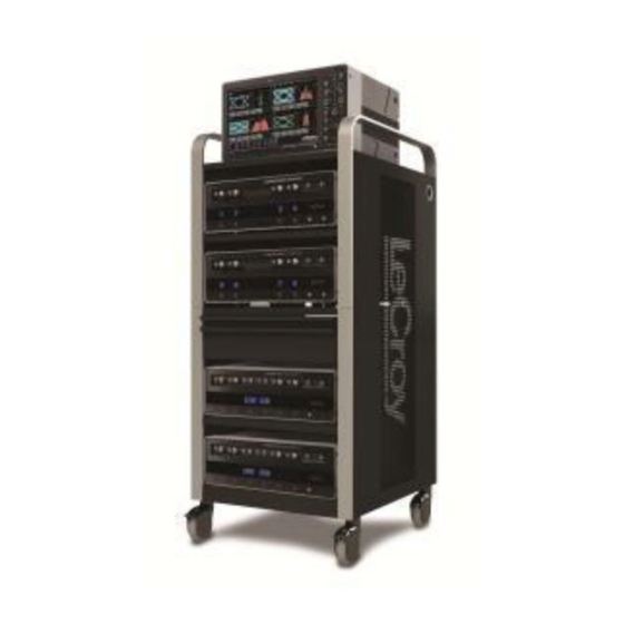
Getting Started Guide LabMaster 10 Zi Hardware Overview LabMaster 10 Zi is a unique modular oscilloscope solution that allows a configuration of more channels at higher bandwidths than conventional four channel oscilloscopes. It is ideally suited for test situations where there are many lanes of serial data to be captured and analyzed simultaneously, crosstalk analysis or for capturing four or more channels at the highest-possible bandwidths for optical coherent modulation... - Page 17 LabMaster 10 Zi Oscilloscopes MCM-ZiMaster Control Module with up to five10-xxZi Acquisition Modules LM10Zi-GSM-E Rev A...
- Page 18 Teledyne LeCroy recommends stacking the modules on top of each other on your bench, inside Teledyne LeCroy's available OC910, or inside of your own rack (modules must be specifically ordered for rack mounting from the Teledyne LeCroy factory).
-
Page 19: Front Of Mcm-Zi Master Control Module
LabMaster 10 Zi Oscilloscopes Front of MCM-Zi Master Control Module The MCM-Zi Master Control Module includes Controls, Display, CPU, and ChannelSync Clock Architecture. All acquisition capability is contained in separate Acquisition Modules. Number and Description Power Host USB Ports 5. Front Panel Control Button Release Switch Detachable Front Panel... -
Page 20: Back Of Mcm-Zi Master Control Module
Getting Started Guide Back of MCM-Zi Master Control Module Number and Description ChannelSync Outputs - 3. 10 MHz Reference The I/O Panel SMA 10 GHz Clock and Clock Input DVI-D Video PCIe 1 Lane Control (Grounded EMI Output Connections (for Shield required when PCIe 4 Lane Data corresponding... - Page 21 Teledyne LeCroy External Display (Zi-EXTDISP-15). However, option cards must be specified when ordering and installed at the Teledyne LeCroy factory into any number of the same five slots used for the Acquisition Modules.. The slot between the DVI-D Video Output connector and the PCIe 4 Lane Data Connection for Channels 1-4 is unavailable.
-
Page 22: Front Of 10-Xxzi Acquisition Module
Teledyne LeCroy recommends stacking the modules on top of each other on your bench, inside Teledyne LeCroy's available OC910 oscilloscope cart or inside of your own rack (modules must be specifically ordered for rack mounting from the Teledyne LeCroy factory). -
Page 23: Back Of 10-Xxzi Acquisition Module
LabMaster 10 Zi Oscilloscopes Back of 10-xxZi Acquisition Module Number and Description ChannelSync 3. PCIe 4 Lane 4. AC Power Inlet SMA 10 GHz Data Output Clock Input ChannelSync PCIe 1 Lane Control Input NOTE: Only Back of MCM-Zi Master Control Module (on page 13)has 10 MHz Reference Clock Input/Output connections. -
Page 24: Front Of Channelsync Mainframe Hub
Getting Started Guide Front of ChannelSync Mainframe Hub Back of ChannelSync Mainframe Hub Number and Description 10 GHz REF Out 4. DATA LINK In 7. SYNC In SYNC Out 5. 10 MHz REF In DATA LINK Out 6. AC Power Inlet LM10Zi-GSM-E Rev A... -
Page 25: The I/O Panel
LabMaster 10 Zi Oscilloscopes The I/O Panel The available connections on I/O panels are the same for all LabMaster 10 Zi configurations. I/O panels are located on the back of the Master Control Module. See Back of MCM-Zi Master Control Module (on page 13) for more information. -
Page 26: Front Panel Controls
Getting Started Guide Front Panel Controls Many Front Panel controls directly correspond with Screen Layout Controls. For example, the Print front panel button is associated with one of the Hardcopy function at Utilities → Utilities Setup → Hardcopy. LM10Zi-GSM-E Rev A... -
Page 27: Touch-Screen Displays
You may operate the instrument using the internal touch-screen display, or attach an external monitor for display. A properly configured LeCroy Zi-EXTDISP-15 integrated second touch screen display will take on all the touch-screen capabilities of the internal display. You can also configure an external display using the optional DVI-D video output connector to drive an external monitor in addition to the internal touch-screen. -
Page 28: Labmaster Setup
Getting Started Guide LabMaster Setup Connecting LabMaster Components LabMaster components are connected by PCIe 1 and 4 Lane, SMA 72", and Power Cables. Use the following procedures to properly connect all parts of your LabMaster. PCIe 1 Lane Cable SYNC Connection(s) Connect each PCIe 1 Lane Control Input on the back of your 10-xxZi Acquisition Modules to a PCIe 1 Lane Output on the MCM-Zi Master Control Module using the PCIe 1 Lane cable(s) provided. - Page 29 LabMaster 10 Zi Oscilloscopes Now, connect the other end of the 1 Lane cable into the SYNC socket on the back of the Acquisition Module. Repeat the previous steps for every additional Acquisition Module in your system. PLEASE NOTE THE FOLLOWING: ...
- Page 30 Getting Started Guide Acquisition Module is connected from the CHANNEL 1-4 output, second from the CHANNEL 5-8 output, third from the CHANNEL 9-12 output, etc. If you are connecting less than 5 of the Acquisition Modules, the PCIe 1 Lane Channel Sync Outputs on the back of the Master Control Module may not be skipped and must be connected in consecutive order into the PCIe 1 Lane Channel Sync Inputs on the back of the corresponding acquisition modules.
-
Page 31: Pcie 4 Lane Datalink Connection(S)
LabMaster 10 Zi Oscilloscopes PCIe 4 Lane DATALINK Connection(s) Continue making the PCI Express connections by cabling the PCIe 4 Lane Data Output on the back of each 10-xxZi Acquisition Module to the PCIe 4 Lane Data Inputs on the back of your MCM-Zi Master Control Module using PCIe 4 Lane cable(s) provided. - Page 32 Getting Started Guide Now, on the back of the Master Control Module, connect the other end of the same PCIe 4 Lane cable into the corresponding PCIe 4 Lane Data Input (labeled DATALINK CHANNEL). LM10Zi-GSM-E Rev A...
- Page 33 LabMaster 10 Zi Oscilloscopes Repeat the previous steps for every additional Acquisition Module in your system. PLEASE NOTE THE FOLLOWING: PCIe 4 Lane Cable plugs are keyed with a single groove along one wide side of the plug. The plug must be inserted into the socket with the groove aligned properly.
-
Page 34: Sma 72" Cables - Channelsync Clock
Getting Started Guide If you are connecting less than 5 of the Slave Acquisition Modules, the PCIe 4 Lane Data Inputs on the back of the Master Control Modulemay not be skipped and must be connected in consecutive order from the PCIe 4 Lane Data Outputs on the back of the corresponding slaves. - Page 35 LabMaster 10 Zi Oscilloscopes SMA 72" Male to Male Cable On the back of the Master Control Module, connect one end of an SMA 72" cable from a SMA 10 GHz Clock Output (labeled REF, unscrew the chain-linked 50 Ω termination, if necessary) . Now, on the back of the Acquisition Module, connect the other end of the same SMA 72"...
- Page 36 Getting Started Guide Repeat the previous steps for every additional Acquisition Module in your system. Cap off unused SMA 10 GHz Clock Outputs on the back of your Master Control Module using the chain-linked 50 Ω terminations provided. LM10Zi-GSM-E Rev A...
-
Page 37: Channelsync Mainframe Hub
LabMaster 10 Zi Oscilloscopes ChannelSync Mainframe Hub The CMH-20 ChannelSync Mainframe Hub provides a simple and effective means to expand a LabMaster system beyond 20 channels (5 Acquisition Modules). This is accomplished without any degradation of the timing accuracy specifications. The Mainframe Hub is populated with cards for each acquisition module (the back panel of the CMH-20 shown below is populated with 20 cards for use with 20 Acquisition Modules, or 80 total channels). -
Page 38: Power Cable And Main Power Switch
Getting Started Guide Power Cable and Main Power Switch Teledyne LeCroy advises that you note the power ratings of the individual modules and connect them to suitably rated circuits. MCM-Zi Control Module comes with an IEC60320 Type C13 power inlet connector. -
Page 39: External Display Setup
LabMaster 10 Zi Oscilloscopes External Display Setup Setting up the Zi-EXTDISP-15External Display involves making DVI-D and USB connections and some touch screen selections. The USB connection is a "hot swap," so there's no need to restart the instrument once you've connected. With your system powered down, attach the Zi-EXTDISP-15 power cord from the power port of the PCIe card on the back of the Zi-EXTDISP-15 monitor to an AC socket. -
Page 40: Removing And Attaching The Front Panel
Getting Started Guide Removing and Attaching the Front Panel Detach the Front Panel Control from the oscilloscope by sliding the detachment lever to the left and pulling at the right. LM10Zi-GSM-E Rev A... - Page 41 USB - A to USB - Mini B cable provided. NOTE: While a standard front panel comes with your Zi oscilloscope, Teledyne LeCroy offers additional standard front panels or a 4 channel version to better suit the way you work. LM10Zi-GSM-E Rev A...
-
Page 42: Labmaster Calibration
Getting Started Guide LabMaster Calibration The ChannelSync™ architecture in LabMaster modular oscilloscope systems utilizes a single 10 GHz distributed clock for all acquisition modules. This provides precise timing alignment and timing accuracy between all channels in all acquisition modules as found in a single, conventional oscilloscope package. - Page 43 LabMaster 10 Zi Oscilloscopes There are two different calibrations that can be performed. Both permit quick and easy deskew of all of the channels in all LabMaster acquisition modules by automatically deskewing all channels to a user-designated reference channel, with the common deskewed reference plane being the input channel connectors on the acquisition module.
- Page 44 Getting Started Guide Touch the SystemSkew Cal button. The System Channel/Trigger Skew Calibration Wizard opens. Connect the Fast Edge output on the front of the Master Control Module to Channel 1, then on the Wizard touch Next. When prompted, connected the Fast Edge output (using the same cable as used to connect to Channel 1) to Channel 5, then touch Next again.
- Page 45 LabMaster 10 Zi Oscilloscopes ChannelSync Calibration This calibration method is most common and is used to eliminate minor static skew (<2 ps) differences between channels, or to account for the addition of cables or probes between the signal and oscilloscope input channel.
- Page 46 Getting Started Guide NOTE: Use the Ref Channel control to select the specific channel you wish to use as a reference when measuring against other channels during your calibration. Select the inputs you want to measure (for example, Input A or Input B).
- Page 47 LabMaster 10 Zi Oscilloscopes When you have finished all channels, a message indicates all measurements have been performed. Touch the Finish button. The ChannelSync™ Calibration dialog shows details about all performed measurements and the deskew values applied. LM10Zi-GSM-E Rev A...
-
Page 48: Probe And Signal Connection Interfaces
Probe and Signal Connection Interfaces Probe Interfaces Teledyne LeCroy oscilloscopes are equipped with a variety of probe interfaces to allow you to connect cables directly to the oscilloscope channels, or to connect probes to the oscilloscope, reducing the need to use costly adapters that may be easily lost or misplaced. -
Page 49: Probes
LabMaster 10 Zi Oscilloscopes Probes Teledyne LeCroy offers a variety probes for use with your oscillocope. The types compatible with the LabMaster 10 Zi are listed below. Visit teledynelecroy.com for specifications and ordering information. Single-Ended - A single-ended, active probe is associated with measuring voltages at high frequencies. -
Page 50: Connecting To 2.92 Mm Probe Interfaces
Connecting to 2.92 mm Probe Interfaces Teledyne LeCroy's LabMaster 10 Zi oscilloscopes utilize a 2.92 mm probe interface for inputs up to 36 GHz. This interface consists of a precision connector and a LEMO power and communication connector. -
Page 51: Probe Dialog
The following figure shows a typical channel setup dialog on a Teledyne LeCroy oscilloscope containing both ProLink (Input A, Upper) and ProBus (Input B, Lower) interfaces. The input selection is on the left- hand side of the dialog box. In this case the A input, the ProLink interface, is selected. - Page 52 Getting Started Guide This additional tab contains specific information on the connected probe. Default values for the probes coupling and attenuation are automatically downloaded from the probe, and these settings along with other attributes are shown on the dialog. The probe dialog showing the connected probe's control attributes. LM10Zi-GSM-E Rev A...
-
Page 53: Basic Controls
Basic Controls Front Panel Control Groupings Miscellaneous Controls / WaveStream Indicator Help - Opens the Teledyne LeCroy Online Assistant. If the second monitor is installed, the online help opens on the second monitor. Default Setup - Resets the oscilloscope's settings to the default configuration. - Page 54 Getting Started Guide WaveStream - Indicates when WaveStream mode is ON. Intensity - Toggles between WaveStream OFF and ON for Analog Persistence and WaveStream ON for Color Persistence. When you turn the knob, if WaveStream is ON, the WaveStream display intensity changes.
-
Page 55: Lm10Zi-Gsm-E Rev A
LabMaster 10 Zi Oscilloscopes Trigger Front Panel Controls Level – Sets the trigger level to 50%. Turn the knob to change the trigger threshold level. The threshold level is indicated on the Trigger label. READY and TRIG'D Indicators - The READY indicator is lit when the trigger is armed. -
Page 56: Horizontal Front Panel Controls
Getting Started Guide Horizontal Front Panel Controls Note: Horizontal front panel controls correspond with screen menu selection: Timebase → Horizontal Setup.. Delay - Toggles between a zero horizontal delay value and the previous horizontal delay value. Turn to change the horizontal delay value. -
Page 57: Vertical Front Panel Controls
LabMaster 10 Zi Oscilloscopes Vertical Front Panel Controls NOTE: You can turn channels on and off using the software as explained in Vertical Overview (on page 85) or from the front of the LabMaster Acquisition Module. Channels – Control channel ON/OFF and which channel is active for the Vertical Offset and Volts/Div knobs controls. -
Page 58: Zoom And Math Front Panel Controls
Getting Started Guide Zoom and Math Front Panel Controls Note: Zoom and Math front panel controls correspond with screen menu selection: Math → Zoom Setup.. Horizontal Position - Resets the horizontal zoom position to zero. Turn to change the horizontal position of the selected math or zoom trace. -
Page 59: Display Dashboard
LabMaster 10 Zi Oscilloscopes Display Dashboard Screen Layout, Groupings, and Controls The instrument's screen is divided into the following main sections: Menu Bar Signal Display Grid Descriptor Labels Dialog(s) The Message Bar NOTE: Many front panel controls directly correspond with screen layout controls. - Page 60 Getting Started Guide Specific Menu Bar functions are referenced using arrow-separated path descriptions. For example, the Save Setup function is referenced as File → Save Setup..NOTE: For common oscilloscope operations, you don't need to use the top menu bar (since you can access most dialogs from the Front Panel or from the Descriptor Labels).
- Page 61 LabMaster 10 Zi Oscilloscopes Trigger Setup - Press to open the Trigger Setup... dialog. Corresponds with screen menu selection: Trigger → Trigger Setup..UICK CCESS ROCESSING UNCTIONS The Processing section allows you to suspend your system from processing data. You can stop data processing, make adjustments, and then resume data processing with the touch of two on-screen buttons.
-
Page 62: The Signal Display Grid
Getting Started Guide The Signal Display Grid The grid area is divided into 8 vertical divisions and 10 horizontal divisions just like any other oscilloscope. Set up the signal display area by touching Display → Display Setup... from the menu bar. The Display dialog offers a choice of grid combinations and can also set the grid intensity. - Page 63 LabMaster 10 Zi Oscilloscopes have it stay fixed as the timebase changes, go to Utilities → Preference Setup... and select the Acquisition dialog to make the setting. Post-trigger Delay - This is indicated by a left-pointing arrow to the lower-left of the grid. Pre-trigger delay is indicated by a right- pointing arrow to the lower-right of the grid.
-
Page 64: Trace Descriptor Labels
Getting Started Guide IGNAL ISPLAY On the Signal Display Grid, the Pop-up menu provides assistance while using the oscilloscope. Clicking on a waveform opens a pop-up menu. From this pop-up menu, you can perform the following functions: Open the Setup dialog for the trace ... - Page 65 LabMaster 10 Zi Oscilloscopes The long and short forms of trace descriptor indicators. Besides channel traces, math and parameter measurement labels are also displayed. Labels are displayed only for traces that are turned on. Vertical and horizontal trace descriptor (labels) are displayed below the grid.
- Page 66 Getting Started Guide CTIONS FOR RACE HORTCUT UTTONS You can access the same functions as the ones produced when using the Signal Display Grid Pop-Up menu just by clicking a trace-descriptor label, which shows its corresponding dialog. From the respective dialog, you're able to access the same functions as Actions for Trace X buttons.
- Page 67 LabMaster 10 Zi Oscilloscopes to create the label. The first time creating a waveform label, Label1 is provided as default text when the Add label button is touched. From this pop-up you can edit existing annotations, change the label placement on the waveform, add labels, remove labels, and toggle the visibility.
-
Page 68: Dialog Area
Getting Started Guide Add another label by touching the Add label button. Delete a label by selecting the label from the list, and then touching the Remove label button. Make labels visible by touching the View labels checkbox. Dialog Area The lower portion of your oscilloscope screen is where information is shown, selections are made, and data is input. - Page 69 LabMaster 10 Zi Oscilloscopes Pop-Up Selector Control for values with varied types. NTRY ONTROLS Most controls can be touched once and you can then provide a value using an attached (or double-touch/click to use the Virtual, on-screen) keyboard. Text entry field for LabNotebook using the Virtual Keyboard. LM10Zi-GSM-E Rev A...
- Page 70 Getting Started Guide OLDER ROWSING ONTROLS These controls allow for navigation to or from folders (on the hard drive or memory device) for retrieving or storing items such as waveforms, LabNotebook entries, to name a few. Folder/File Browsing recall waveform controls. NOTE: The instrument's hard disk is partitioned into C: and D: drives.
- Page 71 LabMaster 10 Zi Oscilloscopes LYOUT ONTROLS Flyout Menus provides a variety of solutions for a particular main area of functionality. It does this by providing a set of buttons subdividing the control into more specific functions on the right-side of the display. An example of Flyout Menu Controls is seen in the Setup front panel button.
- Page 72 Getting Started Guide RECISION NTRY ONTROLS Certain fields requiring precise value entry assist you by having precision entry means. When these controls are selected, you can provide values as follows: Keyboard Touch inside a text entry control and you can manually type the value in using an attached (or double-touch/click to use the Virtual, on-screen) keyboard.
- Page 73 LabMaster 10 Zi Oscilloscopes NOTE: The Slider Bar only appears on 7, 8, 9, and 10 Zi models and only when a physical keyboard is not connected to the instrument via USB. Pop-Up Keypad Some models provide a pop-up Keypad when you touch twice in the same control.
- Page 74 Getting Started Guide Shortcut Buttons Several dialogs contain a row of buttons at the bottom of the dialog. These provide a shortcut to common functions without having to leave the underlying set up dialog. For example, at the bottom of the Channel Setup dialog, these buttons perform the following functions: ...
-
Page 75: Message Bar
LabMaster 10 Zi Oscilloscopes Label - Enables you to attach identifying labels to your waveforms. The labels are preserved when the waveform is saved as a LabNotebook entry and when saved to file. Probe Cal - Cable Deskew - Opens the Probes Cal. dialog where various Gain, Offset, Skew, Source, and Advanced controls are available for probe signal calibration. -
Page 76: Turning On Channels And Traces
Getting Started Guide Turning on Channels and Traces Press the front panel Channel buttons (1-4). You can also press the channel buttons on the front of your Acquisition Modules to turn channels on/off. From menu bar, choose Vertical > Channel <#>. A trace descriptor box appears on the display for each open channel trace. -
Page 77: Timebase
LabMaster 10 Zi Oscilloscopes Timebase Timebase Dialog You can access Timebase settings by: Using the front panel Horizontal controls, Choosing Timebase → Horizontal Setup... from the menu bar Touching the Timebase trace descriptor label. The main Timebase dialog contains sections for choosing Sampling Mode, Timebase Mode, and Real Time Memory. - Page 78 Getting Started Guide Choose TimeBase → Horizontal Setup... to access the Timebase dialog. Touch the DBI tab to show the DBI dialog. Select a pair of inputs to combine by touching the corresponding input button, one from each channel within a single Acquisition Module.
- Page 79 LabMaster 10 Zi Oscilloscopes LM10Zi-GSM-E Rev A...
-
Page 80: Timebase Setup And Control
Getting Started Guide Timebase Setup and Control On the Timebase dialog, touch inside Time/Division and provide a value using your preferred input method. Additional information on using the touch screen controls can be found in the Dialog Area. Touch inside Delay and provide a value. LM10Zi-GSM-E Rev A... -
Page 81: Sampling Modes
LabMaster 10 Zi Oscilloscopes Sampling Modes Sampling Modes Overview Depending on your timebase, you can choose: Single-shot Sampling Mode (on page 75) - Also known as Real Time mode, a series of digitized voltage values sampled on the input signal at a uniform rate. -
Page 82: Single-Shot Sampling Mode
Getting Started Guide Single-shot Sampling Mode A single-shot acquisition is a series of digitized voltage values sampled on the input signal at a uniform rate. It is also a series of measured data values associated with a single trigger event. The acquisition is typically stopped a defined number of samples after this event occurs: a number determined by the selected trigger delay and measured by the timebase. -
Page 83: Sequence Sampling Mode - Working With Segments
LabMaster 10 Zi Oscilloscopes Sequence Sampling Mode – Working with Segments Using Sequence Mode, thousands of trigger events can be stored as segments into the oscilloscope's memory (the exact number depends on oscilloscope model and memory options). This is ideal when capturing many fast pulses in quick succession or when capturing few events separated by long time periods. -
Page 84: Sequence Display Modes
Getting Started Guide How the instrument captures segments Sequence Display Modes The instrument gives you a choice of five ways to display your segments: Adjacent Waterfall (cascaded) LM10Zi-GSM-E Rev A... -
Page 85: Sequence Mode Setup
LabMaster 10 Zi Oscilloscopes Mosaic (tiled) Overlay Perspective NOTE: some display modes have limitations on the number of segments that can be shown at one time. Sequence Mode Setup When setting up Sequence Mode, you define the number of fixed-size segments acquired in single-shot mode (see the instrument specifications for the limits). - Page 86 Getting Started Guide Setting up Sequence Mode (Adjacent) Touch Timebase → Horizontal Setup... on the menu bar. Click the Sequence tab. Under Acquisition Settings, touch inside the Num Segments data entry control and provide a value using your preferred input control method.
- Page 87 LabMaster 10 Zi Oscilloscopes instances when a Num Segments miscount occurs for some reason and the oscilloscope waits indefinitely for an unforthcoming segment. During that time, no oscilloscope functions are accessible. By means of a timeout value, however, the acquisition will be completed, the waveform displayed, and control of the oscilloscope returned to the user after the timeout has elapsed.
-
Page 88: Zooming Segments In Sequence Mode
Getting Started Guide Zooming Segments in Sequence Mode You can zoom individual segments easily using the Zoom front panel button. When you zoom, the zoom traces default to Segment 1. Channel descriptors indicate the total number of segments acquired. Zoom descriptors indicate [Seg #] and #Segments in the Zoom. -
Page 89: Displaying An Individual Segment
LabMaster 10 Zi Oscilloscopes If you want to increase or decrease your horizontal or vertical zoom in small increments, touch the Var. checkbox to enable variable zooming. Now with each touch of the zoom control buttons, the degree of magnification changes by small increments. -
Page 90: Viewing Time Stamps
Getting Started Guide Touch inside the First Selected data entry control and select the first segment you want to display. Use the same method to provide a value in the Number of Selected data entry control. NOTE: In Persistence mode, the segments are automatically overlaid one on top of the other in the display. -
Page 91: Ris Sampling Mode - For Higher Sampling Rates
LabMaster 10 Zi Oscilloscopes RIS Sampling Mode - For Higher Sampling Rates RIS (Random Interleaved Sampling) is an acquisition technique that allows effective sampling rates higher than the maximum single-shot sampling rate. It is used on repetitive waveforms with a stable trigger. The maximum effective RIS sampling rate is achieved by making multiple single-shot acquisitions at maximum real-time sample rate. -
Page 92: Vertical
Getting Started Guide Vertical Vertical Overview You can access Vertical settings using the front panel Vertical controls, by selecting Vertical→ Channel Setup... on the menu bar, or by touching the Channel trace descriptor label. The following screen-shot shows the C1 dialog on a LabMaster. For each open channel trace, a corresponding Cx dialog opens with setup controls. - Page 93 Bandwidth - Bandwidth filters are available at a variety of fixed bandwidth settings. The exact settings vary by model. Probe - Teledyne LeCroy's 1.85 mm and 2.92 mm probe inputs automatically senses probes and sets their attenuation for you. For each channel, the probe attenuation can also be set manually.
-
Page 94: Pre-Processing Controls
Getting Started Guide Pre-Processing Controls Pre-Processing means “before Math processing.” Pre-Processing controls provide the following functions for your respective channel: Averaging - Specifically performs continuous averaging or the repeated addition, with unequal weight, of successive source waveforms. It is particularly useful for reducing noise on signals drifting very slowly in time or amplitude. - Page 95 NOTE: The Cable De-Embedding checkbox is only available if you have the option. To learn more about this software option, Contact Teledyne LeCroy for Support. Interpolation - Linear interpolation, which inserts a straight line between sample points, is best used to reconstruct straight- edged signals such as square waves.
-
Page 96: Response Optimization Modes
When zero group delay is provided at all frequencies, preshoot and overshoot is equalized. Teledyne LeCroy provides three choices for Response Optimization Mode selection. These choices combine a frequency and group delay response to optimize the oscilloscope for particular applications. - Page 97 LabMaster 10 Zi Oscilloscopes Eye Diagram - Flat group delay compensation resulting in equalized preshoot and overshoot. This selection improves the symmetry of serial eye diagrams. In addition, a fourth-order Bessel frequency response is implemented. Flatness - Flat group delay compensation with a brick-wall frequency response.
-
Page 98: Labmaster Channel Setup
Getting Started Guide LabMaster Channel Setup You can adjust the sensitivity and the positioning of the waveforms and set the color of the trace for up to 80 channels on the Channel Setup dialog. The example shown below illustrates Channel Setup with a 20 channel LabMaster. -
Page 99: Labmaster Calibration
LabMaster 10 Zi Oscilloscopes LabMaster Calibration The ChannelSync™ architecture in LabMaster modular oscilloscope systems utilizes a single 10 GHz distributed clock for all acquisition modules. This provides precise timing alignment and timing accuracy between all channels in all acquisition modules as found in a single, conventional oscilloscope package. - Page 100 Getting Started Guide modules by automatically deskewing all channels to a user-designated reference channel, with the common deskewed reference plane being the input channel connectors on the acquisition module. A very high level of accuracy is maintained by using a fast reference signal and averaging for precision.
- Page 101 LabMaster 10 Zi Oscilloscopes Connect the Fast Edge output on the front of the Master Control Module to Channel 1, then on the Wizard touch Next. When prompted, connected the Fast Edge output (using the same cable as used to connect to Channel 1) to Channel 5, then touch Next again.
- Page 102 Getting Started Guide ChannelSync Calibration This calibration method is most common and is used to eliminate minor static skew (<2 ps) differences between channels, or to account for the addition of cables or probes between the signal and oscilloscope input channel.
- Page 103 LabMaster 10 Zi Oscilloscopes Place a checkmark next to the module(s) you want to calibrate and touch the ChannelSync Cal button. The ChannelSync Calibration Wizard opens. NOTE: Use the Ref Channel control to select the specific channel you wish to use as a reference when measuring against other channels during your calibration.
- Page 104 Getting Started Guide The ChannelSync™ Calibration dialog shows details about all performed measurements and the deskew values applied. LM10Zi-GSM-E Rev A...
-
Page 105: Trigger
LabMaster 10 Zi Oscilloscopes Trigger Trigger Overview NOTE: Trigger capabilities on channel 1-4 (i.e., the first acquisition module) are more complete than on channels 5 or higher. Full Edge trigger bandwidth is available on all channels, but SMART triggers are not available on Channel 5 or higher. -
Page 106: Trigger Types
Getting Started Guide MultiStage Triggers - varied forms of triggers including Cascaded, QualFirst, and Qualified allowing varied combinations of triggers and trigger stages. Serial Triggers - provide serial data protocol specific triggering for a wide variety of standards. Trigger Types A set of standard trigger types is available for selection. - Page 107 LabMaster 10 Zi Oscilloscopes NOR), and you can stipulate the high or low voltage logic level for each input independently. Smart These are a specific set of sophisticated trigger types. Smart trigger types are used to set conditions on signals with rare features, like the glitches and others as follows: INDOW A smart trigger occurs when a signal enters or exits a window...
- Page 108 Getting Started Guide The Runt trigger occurs when a pulse crosses a first threshold line, but fails to cross a second threshold line before re- crossing the first. Other defining conditions for this trigger are the edge (triggers on the slope opposite to that selected) and runt width.
-
Page 109: Serial Trigger
LabMaster 10 Zi Oscilloscopes IRST In single trigger mode, QualFirst arms the oscilloscope on the A event, and then triggers on all subsequent B events. NOTE: This button is enabled when using the sequence sampling mode. It is commonly used in sequence mode for disk drive applications with the index pulse defined as the A qualifier signal and the servo gate signal as the B triggering events. -
Page 110: Trigger Settings
Channel 4 would still be the input channel for the serial trigger signal. Complete information on the operation of this trigger can be obtained in the Teledyne LeCroy Serial Data Debug Solutions manual posted on the Teledyne LeCroy website. Trigger Settings... -
Page 111: Trigger Setup
LabMaster 10 Zi Oscilloscopes Turn this knob to adjust the level of the trigger source or the highlighted trace. Level defines the source voltage at which the trigger will generate an event: a change in the input signal that satisfies the trigger conditions. - Page 112 Getting Started Guide With DC coupling, all of the signal's frequency components are coupled to the trigger circuit for high-frequency bursts. Touch inside the trigger Slope control and choose the direction of the trigger voltage transition used for generating a particular trigger event.
-
Page 113: Optimize For Hf
LabMaster 10 Zi Oscilloscopes information on using the touch screen controls can be found in the Dialog Area. Provide a voltage level (in millivolts). NOTE: Once specified, Trigger Level and Coupling are the only parameters remaining unchanged as you switch from trigger mode to trigger mode for each trigger source. -
Page 114: Holdoff By Time Or Events
Getting Started Guide In Range and Out of Range conditions can be further specified by choosing to set: Limits and assigning Upper and Lower Values to the range. Delta and assigning Nominal width and Delta. NOTE: Width Condition settings are summarized on the far right of the dialog. - Page 115 LabMaster 10 Zi Oscilloscopes FF BY Sometimes you can achieve a stable display of complex, repetitive waveforms by placing a condition on the time between each successive trigger event. This time would otherwise be limited only by the input signal, the coupling, and the instrument's bandwidth. Select a positive or negative slope, and a minimum time between triggers.
-
Page 116: Auxiliary Input Trigger
Getting Started Guide Edge Trigger with Holdoff by Events (in this example, two events). The bold edges on the trigger source indicate that a positive slope has been selected. The broken, upward-pointing arrows indicate potential triggers, while the bold ones show where triggers actually occur after the holdoff expires. -
Page 117: Triggerscan
LabMaster 10 Zi Oscilloscopes TriggerScan TriggerScan is a debugging tool (available for any trigger type) that helps you quickly find rare waveform glitches and anomalies. With TriggerScan, you can build a list of trigger setups to look for rare events and automatically sequence through each one. -
Page 118: Training Triggerscan
Getting Started Guide Training TriggerScan The TriggerScan Trainer inspects a currently acquired waveform and automatically builds a list of common trigger setups used to find rare events. NOTE: Run the Trainer if you want to change the trigger types or if you change the channel or signal. -
Page 119: Starting Triggerscan
LabMaster 10 Zi Oscilloscopes Starting TriggerScan After you have run the Trainer, the Trigger List displays a list of smart trigger setups. You can add or remove trigger setups. You can also update the selected smart trigger setup. Once you have made any changes to the Trigger List, you are ready to start scanning. -
Page 120: Saving Triggerscan Setups
Getting Started Guide oscilloscope automatically sequences through all the trigger setups. PLEASE NOTE THE FOLLOWING: You can tune the dwell time that the oscilloscope waits before loading the next trigger setup using the Dwell Time data entry control. If you have Persistence display mode enabled, all trigger events are recorded on the display. -
Page 121: Viewing Waveforms
Channel traces are typically 8-bits of vertical data, whereas Math traces are 16-bits of vertical data. Teledyne LeCroy grids consist of eight vertical divisions. When displaying channel traces on the grid, use of less than full-grid amplitude results in some reduced vertical resolution and accuracy. -
Page 122: Display Setup
Getting Started Guide Display Setup Access and adjust the different display configurations on the oscilloscope using the following steps: NOTE: Not all grid styles are available on all instruments. Grid styles vary based on both oscilloscope model and whether or not you have the SDA III software option loaded on your oscilloscope. - Page 123 LabMaster 10 Zi Oscilloscopes Touch the Axis labels checkbox to permanently display the values of the top and bottom grid lines (calculated from volts/div) and the extreme left and right grid lines (calculated from the timebase). Choose a line style for your trace: solid Line or Points as follows: Touch inside the trace Intensity data entry control if you want to change the value.
-
Page 124: Moving Traces From Grid To Grid
Getting Started Guide Moving Traces from Grid to Grid You can move traces from grid to grid with the touch of a button. Double-touch the trace descriptor label to activate the waveform you want to move and open the setup dialog. Touch the Next Grid shortcut button at the bottom of the setup dialog. -
Page 125: Persistence
LabMaster 10 Zi Oscilloscopes Touch the Dual button on the Display Mode section of the Display dialog. Touch inside the Grid control on the Grid Mode section of the dialog. The Select Grid pop-up is shown. Touch the Dual Display category and choose from Single/Single, Dual/Dual, and Quad/Quad options. - Page 126 Getting Started Guide 4. Touch inside the Saturation data entry control and provide a whole number integer. 5. Touch inside the Persistence time data entry control and make a selection from the pop-up menu. Setup Each Input Channel Individually 1. Touch the Per Trace button. 2.
-
Page 127: Wavestream Display Mode
LabMaster 10 Zi Oscilloscopes WaveStream Display Mode This fast viewing mode provides brightness-graded intensity with a decay time similar to the action of phosphor on an analog screen. WaveStream mode operates at up to 80 GS/s with an update rate of up to several thousand waveforms/second for better capture of higher frequency abnormal events. - Page 128 Getting Started Guide Color Persistence - The button behaves the same way as Analog. However, the grid display shows a color waveform where red indicates most frequent occurrences while blue denotes the less frequent. Instead of using the knob, you can provide values for Intensity (same control on Display and Persistence dialogs) or Saturation controls.
-
Page 129: Zooming Waveforms
LabMaster 10 Zi Oscilloscopes Zooming Waveforms Zooming Waveforms Overview You can magnify a selected region of a waveform using the Zoom function. On Zi model oscilloscopes, you can display up to four Zoom (Z1 - Z4) and eight Math Zoom traces (F1 - F8). You can zoom: ... -
Page 130: Zooming A Single Channel
Getting Started Guide Previewing Zoomed Waveforms When you zoom a waveform, a preview of the zoomed area is shown on the Preview section of the Zx dialog. Zooming a Single Channel The Zoom button appears as a standard button at the bottom of the channel Cx Vertical Adjust setup dialog for you to create a zoom trace of your input waveform. - Page 131 LabMaster 10 Zi Oscilloscopes If you want to zoom in or out in large standard increments with each touch of the zoom control buttons, leave the Var. checkbox unchecked. If you want to set exact horizontal or vertical zoom factors, touch inside the Horizontal Scale/div data entry control and provide a time-per-div value using your preferred input control method.
-
Page 132: Touch-And-Drag Zooming
Getting Started Guide Vertical Position - Press to reset the vertical zoom position to zero. Turn to change the vertical position of the selected math or zoom trace. Vertical Ratio - Press to toggle between fixed and variable vertical zoom ratio adjustment. -
Page 133: Quickly Zooming Waveforms And Multiple Waveforms
LabMaster 10 Zi Oscilloscopes Quickly Zooming Waveforms and Multiple Waveforms Quickly create a Zoom trace by either pressing the front panel Zoom button or touching the Zoom button on the respective channel dialog. Turning Off Zoom Turn off a Zoom by either pressing the front panel Zoom button again. On the corresponding Zoom dialog, touch the Trace On checkbox to remove the check mark and disable the zoom trace. -
Page 134: Cursors
Getting Started Guide Cursors Cursors Overview Cursors are important tools that aid you in measuring signal values. Cursors are markers - lines, cross-hairs, or arrows - that you can move around the grid or the waveform itself. Use cursors to make fast, accurate measurements and eliminate guesswork. -
Page 135: The Cursors Dialog
LabMaster 10 Zi Oscilloscopes PLEASE NOTE THE FOLLOWING: The bottom cursor knob adjusts relative cursors. It does not work with absolute cursor types. Previously setup cursor positions are preserved for subsequent displays. Changing cursor positions or measurement modes are always available using touch screen or front panel control methods as previously mentioned. - Page 136 Getting Started Guide Vertical Abs - Provides a single, dashed, horizontal line and cross- hair marking for the specific cursor location. None of the Show controls are provided; however, the Position 1 control is enabled on the right of the dialog. ...
-
Page 137: Cursors On Math Functions
LabMaster 10 Zi Oscilloscopes Cursors on Math Functions You can place cursors on a math function whose X-axis has a dimension other than time (FFT, for example). With a Math trace setup for either an FFT or a Histogram, if you then access the Standard Cursors dialog (Measure →... -
Page 138: Measurements
Getting Started Guide Measurements Measurement Parameters Overview Parameters are measurement tools that determine a wide range of waveform properties. Use them to automatically calculate many attributes of your waveform, like rise-time, rms voltage, and peak-to- peak voltage, for example. There are parameter modes for the amplitude and time domains, custom parameter groups, and parameters for pass and fail testing. -
Page 139: Parameter Setup
LabMaster 10 Zi Oscilloscopes Touch any of the measurements on the table display (under the grid display area) to show its corresponding Measure dialog. Parameter Setup Touch the parameter tab (Px) of an unused location or one that you want to change. Under Type, select a measurement type: Measure On Waveforms applies measurements directly on the waveform as indicated on the Source1 control. - Page 140 Getting Started Guide Advanced Web Edit uses Teledyne LeCroy's Processing Web for measurement setup. This feature, available with the XWEB option, allows you to chain practically unlimited math functions together for operation on your waveform measurements. Touch inside the Source1 field and select a channel, math trace, memory trace, or other waveform to be measured.
-
Page 141: Measure Modes
LabMaster 10 Zi Oscilloscopes In the mini-dialog to the right of the main setup dialog, touch the Gate tab to narrow the span of measurement. Touch the Accept tab to define parameter values to be used in the measurement. Measure Modes The selections for Measure Mode allow you to quickly apply parameters for standard vertical and standard horizontal setups, and custom setups. -
Page 142: Help Markers
Getting Started Guide Selecting Measure Modes Touch Measure → Measure Setup... on the menu bar. Under Measure Mode, select the Std Vertical or Std Horizontal buttons. NOTE: You can customize parameters by touching My Measure. Learn more in Customizing a Parameter (on page 1). Touch inside the Source data entry control and choose a source for which the measurements should apply. - Page 143 LabMaster 10 Zi Oscilloscopes Standard Horizontal Parameter Help Markers Standard Vertical Parameter Help Markers LM10Zi-GSM-E Rev A...
- Page 144 Getting Started Guide Turning On Markers Touch Measure → Measure Setup... on the menu bar. Select mode Std Vertical, Std Horizontal, or My Measure. Touch the Show All button (as follows) to display Help Markers for every parameter being measured on the displayed waveform (C2 in the previous examples).
-
Page 145: Math
LabMaster 10 Zi Oscilloscopes Math Teledyne LeCroy offers a deep toolset of math functions always growing and changing to provide superior functionality. Math functions can be applied to waveforms displayed on any channel Cx, memories Mx, other math traces Fx (to sequence functions), or parametersPx. - Page 146 Getting Started Guide Math functions are categorized into Basic and Special. Optionally, make any other settings on the Function (Fx) dialog you wish: Change the source waveform on which math is performed in Source 1. Touch the dual function button to chain functions. LM10Zi-GSM-E Rev A...
- Page 147 LabMaster 10 Zi Oscilloscopes To view the output in a graphical format (e.g., Histogram, Track, or Trend), touch the graph button, then touch Graph with to select a mode. Use the web edit button to access the Processing Web and create highly detailed math functions.
-
Page 148: Math And Measurement Analysis
Getting Started Guide Math and Measurement Analysis Most Teledyne LeCroy oscilloscopes calculate measurements for all instances in the acquisition, enabling a variety of unique capabilities for advanced waveform analysis. This includes the ability to rapidly and thoroughly analyze a long memory acquisition and calculate thousands or millions of parameter values, or find anomalous measurements, or apply a variety of mathematical functions to an acquisition. -
Page 149: Track Vs. Trend
LabMaster 10 Zi Oscilloscopes Track vs. Trend Both Track and Trend are tools that can be used to plot measurement data and observe variations with respect to time. Differences between Track and Trend are summarized in the following table: Characteristic Track Trend Representation... -
Page 150: Viewing Histograms
Getting Started Guide Viewing Histograms Histograms are graphical representations of data which divide it into intervals or bins. These intervals/bins are plotted on a bar chart such that the bar height relates to the number of data points inside each interval/bin. - Page 151 LabMaster 10 Zi Oscilloscopes Choose the math trace (F1-F12) in which to display the histogram. Touch the new Fx descriptor box to display the Function dialog, then touch the Histogram tab at the right to display the Histogram right-hand dialog. Touch #Values and enter the number of parameter values that will be contained in the histogram.
- Page 152 Getting Started Guide If you do not see a resulting histogram (i.e., you see a track or trend), touch Graph with: and choose Histogram from the pop-up menu. Touch the Histogram tab at the right to display the Histogram right-hand dialog. Touch #Values and enter the number of parameter values that will be contained in the histogram.
-
Page 153: Persistence Histogram
LabMaster 10 Zi Oscilloscopes Select Show Histicons. NOTE: For measurements set up in My Measure, you can quickly display an enlarged histogram of a thumbnail histogram by touching the Histicon you want to enlarge. The enlarged histogram appears superimposed on the trace it describes. This does not apply to Std Vertical or Std Horizontal measurements. -
Page 154: Viewing Trends
Getting Started Guide ERSISTENCE IGMA Using this math operator, you can enter a scale, measured in standard deviations, by which to create a new waveform. Viewing Trends This procedure explains how to view the Trend of a math function or measurement parameter applied to a waveform. -
Page 155: Viewing A Track
LabMaster 10 Zi Oscilloscopes the lower-right side of the screen). NOTE: Turning off a trace for which trend data is being collected resets the trend. If it is necessary to continue data collection for the trend, first create a zoom trace of the channel trace (before turning off the channel trace). -
Page 156: Pass/Fail Parameter Testing
Getting Started Guide The Track is then shown along with its respective trace descriptor label for the selected math function. Touch the newly displayed Track math function trace label if you want to change any settings in the Track dialog: Pass/Fail Parameter Testing Pass/Fail Parameter Testing Overview Access the main Pass/Fail dialog by selecting Analysis →... - Page 157 LabMaster 10 Zi Oscilloscopes When you have each of the Qx dialogs configured and enabled as desired, you can then begin your testing and turn them all on or off using the Testing checkbox on the main Pass/Fail dialog. You can also specify Actions for all or some of your conditions using the Actions dialog.
- Page 158 Getting Started Guide Your test data is shown on the Table display area shown in the previous screen-shot. Pass/Fail Setup on Qx Dialogs The Qx dialog contains several controls for specifying your Pass/Fail conditions. IALOG ONTROLS Use the Source1 control to specify the waveform you'll use for your Condition.
-
Page 159: Comparing A Single Parameter
LabMaster 10 Zi Oscilloscopes Select the desired condition. NOTE: Right-hand dialogs on the Qx dialog vary based on the Pass/Fail condition selected. ONDITION ASED IGHT IALOGS Boolean Identity This condition simply passes through the input values as the desired result. Param and Dual Param Compare Using the Param Compare conditions, each Pass/Fail input (Qx) can compare a different parameter measurement to a user-defined limit (or... -
Page 160: Comparing Dual Parameters
Getting Started Guide By selecting All, the test are true only if every waveform falls within the set limit. Selecting Any makes the test true if just one waveform falls within the limit. Touch inside the Condition field on the ParamCompare part of the dialog and select a math operator from the pop-up menu. - Page 161 LabMaster 10 Zi Oscilloscopes Touch inside the Condition field in the main dialog and select DualParamCompare. Touch inside the Source1 and Source2 fields and select a source from the pop-up menu. Touch inside the ParamCompare mini-dialog field and select a source from the pop-up menu.
- Page 162 Getting Started Guide Actions Dialog Various configurations can be made to all or some of your Pass/Fail conditions using the Actions dialog. By touching the Stop Test checkbox in the Actions dialog, you can set up the test to end after a predetermined number of sweeps that you decide.
-
Page 163: Initial Setup
LabMaster 10 Zi Oscilloscopes Pass/Fail Boolean Conditions All True All False Any True Any False All Q1 to Q4 Or All Q5 to Q8 Any Q1 to Q4 And Any Q5 to Q8 ESTING ETUP Initial Setup Touch Analysis → Pass/Fail Setup... on the menu bar. Touch the Actions tab. - Page 164 Getting Started Guide want to have the results printed (and your oscilloscope is not equipped with a printer) make sure your instrument is connected See Print Setup Dialog in the to a local or network printer. online Help. If you want to save your waveform automatically, touch the Save Setup...
-
Page 165: Mask Testing
LabMaster 10 Zi Oscilloscopes Mask Testing Users may load or create a pixel-based mask on the display grid using a variety of methods. Test conditions can be set, and a pass/fail result returned based on whether the condition was found to be true or false. The source of the mask is always a trace (Channel, Zoom, Math waveform). - Page 166 Getting Started Guide For more detailed information about these right-hand dialogs, refer to Pass/Fail Testing (on page 149). Quick Access to Pass/Fail Setup Dialogs You can quickly gain access to the 1) Pass/Fail dialog, 2) Qx setup dialog, or the 3) Actions dialog by touching one of the sections below the grid display.
-
Page 167: Removing A Mask From The Display
LabMaster 10 Zi Oscilloscopes Removing a Mask from the Display Quickly remove a mask by accessing the Qx dialog. On the Load Mask right-hand dialog, click the Delete button. Mask testing can be done using an existing mask, or by using a mask created from your actual waveform, with vertical and horizontal tolerances that you define. - Page 168 Getting Started Guide Right-Hand Dialogs Select a truth condition from the Test is True when buttons. From the Show Markers section of the dialog, choose whether or not to display mask violations by touching either Off or On. To load a pre-existing mask, use the Load Mask right-hand dialog.
-
Page 169: Wavescan Overview
LabMaster 10 Zi Oscilloscopes WaveScan Overview WaveScan enables you to search for unusual events in a single capture, or to scan for an event in many acquisitions over a long period of time. You can select from more than 20 search modes (frequency, rise time, runt, duty cycle, etc.), apply a search condition (slope, level, threshold, hysteresis), and begin scanning in a post-acquisition environment. -
Page 170: Signal Views
Getting Started Guide Signal Views WaveScan provides distinct views of your signal: Source View highlights all occurrences of edges that meet your criteria. Scan Overlay places all captured edges one on top of the other in a separate grid. You can apply monochromatic persistence in this view. -
Page 171: Customization Overview
LabMaster 10 Zi Oscilloscopes Measurement Mode – Searches from 2 to 64 bits; ideal for bursted patterns where a PLL cannot lock. Bus Pattern Mode – Searches from 2 to 64 bits; enhances MSO search capabilities. Parameter Measurements Besides parameter measurements made during acquisition, post- acquisition measurements can also be made. - Page 172 Getting Started Guide calculating parameters, or performing math functions on the waveform—in exactly the same way as for a captured waveform. You can program the oscilloscope yourself. The instrument does not just exchange data with other programs; it provides true interaction with these other programs, which allows you to write the parameter, function, or program you need to do the exact job you want to do and make it part of the oscillosocpe interface.
-
Page 173: Documenting Work With Labnotebook
Documenting Work with LabNotebook LabNotebook Overview Teledyne LeCroy's LabNotebook feature extends the documentation capabilities of your oscilloscope. It allows you to create an annotated notebook entry containing all displayed waveforms, the setup of the DSO, and user-supplied annotations. The notebook entry can then be converted to hardcopy format - .pdf, .rtf, or .html - and printed or e-... -
Page 174: Using Labnotebook
Getting Started Guide Using LabNotebook Choose File → LabNotebook from the menu bar to display the LabNotebook dialog. This dialog is where you can store and create LabNotebook entries. You also can view, create, E-mail, and select an output format for your reports. - Page 175 LabMaster 10 Zi Oscilloscopes Touch inside the Title control and provide a value using your preferred input control method. If desired, touch inside the Description field, provide information and touch Save. The My Notebook Entries list shows the entries you've already stored on your instrument.
-
Page 176: Flashback Recall
Getting Started Guide Flashback Recall With a stored entry selected on the My Notebook Entries section of the dialog, touch the Flashback (Recall) button to return your instrument to the state it was in when the Notebook Entry was saved. Exit Flashback by touching the Undo Flashback button in the top-right corner of the screen, or the Auto Trigger front panel control. - Page 177 LabMaster 10 Zi Oscilloscopes Find Notebook Entries You can use the Up and Down arrows to move through your My Notebook Entries list one row at a time. To filter a large amount of entries: Touch the Filter button. The Filter Entries pop-up is shown. To filter by date, check Show only records created on this date, and enter a Day, Month, and Year.
- Page 178 Getting Started Guide View Notebook Entries With a notebook entry selected, touch the View button to display a preview of the entry in report format. Exit the preview by touching the Close button at the right of the dialog. Create Reports from Notebook Entries Select a report from the My Notebook Entries list.
- Page 179 LabMaster 10 Zi Oscilloscopes NOTE: Personalize your LabNotebook reports using the Advanced dialog. Choose Output Format You can select an output Format of HTML, RTF, or PDF. Delete Notebook Entry The Delete button removes the specific row selected on the My Notebook Entries list while the Delete All button removes every entry on the list.
-
Page 180: Save/Recall
Getting Started Guide Save/Recall Save/Recall Overview The Save/Recall section allows for storage and retrieval of Waveforms, Table Data, and Instrument Setups. It even provides Disk Utilities for arranging the file/folder structure on your instrument's hard drive. Access each Save/Recall function (Waveform, Table, Setups) from the File menu on the menu bar. - Page 181 LabMaster 10 Zi Oscilloscopes Your setup file is then saved to the D:\Internal Setups location on your instrument and the current date/time is shown above the SetupX data entry control. ETUP IRECTLY TO A Touch the File button on the Save To section on the dialog. Touch inside the Save files in directory control and provide a path to the destination folder.
-
Page 182: Saving And Recalling Waveforms
Getting Started Guide Restoring Default Settings To reset the settings to the default configuration, press the front panel Default Setup button or the Recall Setup dialog Recall Default button. Following are some of the default settings for your oscilloscope: Channels 1 and 2 are turned on at 50 mV/div, 0V offset, linear interpolation ... - Page 183 If you are saving to a file, touch the Data Format control and select a format type. Binary - saves the file to Teledyne LeCroy's binary file format. This format is documented in various Remote Control Manuals for Teledyne LeCroy Oscilloscopes.
- Page 184 Getting Started Guide ASCII -Text output file (.txt extension). MATLAB - Text output file compatible with MATLAB (.dat extension). Excel - Text output file compatible with Excel (.csv extension). MathCad - Text output file compatible with Excel (.prn extension).
- Page 185 LabMaster 10 Zi Oscilloscopes PLEASE NOTE THE FOLLOWING: Select Audio to save your waveforms into the .wav format. The WaveML format, which enables XML output, is used for persistence traces. Vector Signal Analysis (VSA) Support Users with the VSA Support Software option can choose With Header from the SubFormat control.
-
Page 186: Recalling Waveforms
Getting Started Guide saved. The file name is assigned automatically and is shown under the control. 4. Touch the Save Now! button. Recalling Waveforms NOTE: Only .trc files saved in binary format can be recalled into the oscilloscope. Access the Recall Waveform dialog by either selecting File → Recall Waveform from the menu bar or clicking the Recall Waveform button on the main Save/Recall dialog. - Page 187 LabMaster 10 Zi Oscilloscopes When saving a File, touch inside the Show only files control and select an area to limit the search (channels, math functions, or memory). Touch inside the Recall files from directory data entry control and provide the path. You can also touch the Browse button and navigate to the file.
-
Page 188: Utilities
Getting Started Guide Utilities The Utilities menu gives access to: Utilities Setup - Settings to control... Disk Utilities - Tools for... Preference Setup - Settings to control the general functioning of the display, print, e-mail and other features. Utilities Setup Utilities Dialog Selecting Utilities →... -
Page 189: Adding Software Options
10 seconds. Service button launches a section of the application reserved for qualified Teledyne LeCroy personnel. An access code is required to enter this section. Status The Status dialog displays information about your instrument, including model number, serial number, firmware version. - Page 190 GPIB is an option that either requires a GPIB card to be installed in an open card slot on your oscilloscope or the use of an external USB to GPIB Teledyne LeCroy accessory. Your particular oscilloscope may support both, or only one of the options/accessories.
- Page 191 LabMaster 10 Zi Oscilloscopes reconfigure the oscilloscope's connection if it is already connected to the network or make a new connection. NOTE: Your instrument allows you to restrict remote control access to certain clients. To restrict access, under Security, touch the Yes button and enter the IP addresses or domain name server names you want to restrict separated by a comma.
-
Page 192: Printing And Hardcopy Functions
Getting Started Guide Printing and Hardcopy Functions The Print functions are accessed on most instruments by: Choosing File → Print Setup... or Print from the menu bar, or Pressing the front panel Print button and using the corresponding Flyout Menu. Selecting Print Setup... - Page 193 LabMaster 10 Zi Oscilloscopes On the Utilities Hardcopy dialog, touch the Printer icon. Touch the Add Printer button. A Microsoft Windows® Devices and Printers window opens where you can add a printer. You can also assign a default printer from this same Devices and Printers window.
- Page 194 Getting Started Guide Touch the Hardcopy Area control to choose which part of the screen you want to print from the pop-up menu. Choose Grid Area Only if you do not need to print the dialog area and you only want to show the waveforms and grids.
- Page 195 LabMaster 10 Zi Oscilloscopes functionality, like printing to the clipboard or to a file, or e-mailing your screen images. You can also choose to print the waveform and grids only, the waveform and grids with the dialog, or the entire screen . RINT TO The File selection on the Hardcopy tab saves the screen image as a file to storage media such as a USB drive or hard drive.
- Page 196 Getting Started Guide Touch inside the File Name data entry control and provide a name for the display image using your preferred input control method. Additional information on using the touch screen controls can be found in the Dialog Area. Touch inside the Directory data entry control and provide the folder path for the resulting printout, or touch the Browse button and navigate to the folder.
- Page 197 LabMaster 10 Zi Oscilloscopes Hardcopy Dialog Method Touch Utilities → Utilities Setup... and click the Hardcopy tab. On the Hardcopy dialog, touch the Clipboard button. Touch the Colors control and choose Standard to print the screen as it appears, Print to print the waveforms on a white background, or Black &...
- Page 198 Getting Started Guide Hardcopy Dialog Method Touch Utilities → Utilities Setup... and click the Hardcopy tab. On the Hardcopy dialog, touch the E-Mail button. Touch inside the File Format data entry control and select a graphic file format from the pop-up menu. Touch the Colors control and choose Standard to print the screen as it appears, Print to print the waveforms on a white background, or Black &...
-
Page 199: Aux Output
LabMaster 10 Zi Oscilloscopes Aux Output The Aux Output dialog allows you to specify Auxiliary and Calibration Output details. If you want a specialized output, touch one of the following buttons under Use Auxiliary Output For: Square Wave, Trigger Enabled, Trigger Out, Pass/Fail, or Off. NOTE: If Pass/Fail is selected on this Use Auxiliary Output For section of the dialog, a Pulse Duration data entry control is made available. - Page 200 Getting Started Guide Use the Auxiliary Output to send the following signals to other instruments: Trigger Enabled - This function can be used as a gating function to trigger another instrument when the oscilloscope is ready. Trigger Out - This function can be used to trigger an external oscilloscope.
- Page 201 LabMaster 10 Zi Oscilloscopes Date/Time From the Date and Time tab on the Utilities dialog, you can set the oscilloscope date. time, time zones, and daylight savings time. ANUAL ETHOD Enter the Hour, Minute, Second, Day, Month, and Year. After providing values, touch the Validate Changes button.
-
Page 202: Disk Utilities
Getting Started Guide Options The Options dialog is used to add or remove software options. To learn about available options, Contact LeCroy for Support (on page 210), or visit our website at www.teledynelecroy.com/options. This dialog also displays the ScopeID and Serial #. -
Page 203: Preferences Setup
LabMaster 10 Zi Oscilloscopes Delete All Files in a Folder Touch inside the Current folder field and enter the path to the folder containing the files to be deleted. Touch the Browse button and navigate to the folder. With the folder selected, touch the Empty Folder button. Create a Folder Touch the Create button. -
Page 204: Preferences Dialog
Getting Started Guide Preferences Dialog Choose Utilities → Preference Setup... to access the main Preferences dialog. The following settings are made from this dialog: Audible Feedback - To have audible confirmation each time you touch a screen or front panel control, check the Enable box in the Audible Feedback section of the dialog. - Page 205 LabMaster 10 Zi Oscilloscopes Acquisition Click the Acquisition tab of the Preferences dialog to access Acquisition settings. This allows you to make more fine-grained adjustments to how the instrument performs acquisition than is available using the pre-set selections on the Preferences dialog. You can view a summary of your Acquisition (and other) settings by accessing Status dialogs from the menu bar: ...
- Page 206 Getting Started Guide Delay Setting constant in - allows you to specify how Horizontal scale changes are displayed. Choose either: Time - As the timebase changes, keep the horizontal offset indicator stationary. With this selection, the trigger point could move off the grid.
- Page 207 LabMaster 10 Zi Oscilloscopes E-Mail Use the Utilities E-mail dialog to set up e-mail on the oscilloscope. E-Mail Server- Choose a server protocol from the following options: MAPI (Messaging Application Programming Interface) is the Microsoft interface specification that allows different messaging and workgroup applications (including e-mail, voice mail, and fax) to work through a single client, such as the Exchange client.
- Page 208 Getting Started Guide Color Use this dialog to customize the colors used for Channels, Math, and Memory traces when shown on your instrument and when used in print output. NOTE: These color settings match a waveform on the grid display (both on-screen and printed) and show consistently on corresponding dialogs, tables, and trace descriptor labels.
- Page 209 Other Preferences are set on the Miscellaneous dialog. ARDCOPY UTPUT Add the Teledyne LeCroy Logo to hardcopies of your grid displays by checking Print Teledyne LeCroy Logo When Printing Grid Area Only in the Hardcopy section of the dialog. Use the grid area below the checkbox to select where to place the logo.
-
Page 210: System Recovery
Severe cases may require a reloading of the base operating system and oscilloscope application. Teledyne LeCroy provides you with the Acronis recovery application and a backup image in a partition (drive D: ) of the instrument's hard drive. -
Page 211: Reference
The oscilloscope is warranted for normal use and operation, within specifications, for a period of three years from shipment. Teledyne LeCroy will either repair or, at our option, replace any product returned to one of our authorized service centers within this period. However, in... -
Page 212: Specifications
Getting Started Guide Specifications NOTE: Specifications are subject to change without notice. Detailed specifications are maintained on the product Datasheet available at www.teledynelecroy.com. Always check the website for the most up to date specifications. Certifications This section contains the instrument’s Electromagnetic Compatibility (EMC), Safety and Environmental certifications. - Page 213 Performance Criteria "C" applied for 70%/25 cycle voltage dips and for 0%/250 cycle voltage interruption test levels per EN61000-4-11. European Contact: Teledyne LeCroy Europe GmbH Waldhofer Str 104 D-69123 Heidelberg Germany Tel: (49) 6221 82700 &...
-
Page 214: Safety Compliance
Getting Started Guide Australia / New Zealand Contacts: Vicom Australia Ltd. Vicom New Zealand Ltd. 1064 Centre Road 60 Grafton Road Oakleigh, South Victoria 3167 Auckland Australia New Zealand Safety Compliance EC D –L ECLARATION OF CONFORMITY OLTAGE The oscilloscope meets intent of EC Directive 2006/95/EC for Product Safety. -
Page 215: Environmental Compliance
LabMaster 10 Zi Oscilloscopes Protection Class I: grounded equipment, in which protection against electric shock is achieved by Basic Insulation and by means of a connection to the protective ground conductor in the building wiring. U.S. N ATIONALLY ECOGNIZED GENCY ERTIFICATION The oscilloscope has been certified by Underwriters Laboratories (UL) to... -
Page 216: Iso Certification
Getting Started Guide of your Teledyne LeCroy product, please visit teledynelecroy.com/recycle. ESTRICTION OF AZARDOUS UBSTANCES This instrument has been classified as Monitoring and Control Equipment, and is outside the scope of the 2011/65/EU RoHS Directive. ISO Certification Manufactured under an ISO 9000 Registered Quality Management System. -
Page 217: Contact Teledyne Lecroy
Ph: 800-909-7112 / 408-653-1260 customersupport@teledynelecroy.com psgsupport@teledynelecroy.com European Headquarters Singapore, Oscillosocpes Teledyne LeCroy SA Teledyne LeCroy Singapore Pte Ltd. 4, Rue Moïse Marcinhes Blk 750C Chai Chee Road #02-08 Case postale 341 Technopark @ Chai Chee 1217 Meyrin 1 Singapore 469003... -
Page 218: End-User License Agreement For Teledyne Lecroy ® X-Stream Software
CONVENTION DE MÊME QUE TOUS LES DOCUMENTS Y COMPRIS TOUT AVIS QUI S'Y RATTACHÉ, SOIENT REDIGÉS EN LANGUE ANGLAISE. GRANT OF LICENSE. 1.1. License Grant. Subject to the terms and conditions of this EULA and payment of all applicable fees, Teledyne LeCroy grants LM10Zi-GSM-E Rev A... - Page 219 (other than Instruments and Your Software) without the express prior written consent of Teledyne LeCroy. The Software Product is licensed as a single product. Its component parts may not be separated for use by more than one user.
- Page 220 Software Product unless you are properly licensed to use a product identified by Teledyne LeCroy as being eligible for the upgrade ("Underlying Product"). A Software Product labeled as an "upgrade" replaces and/or supplements the Underlying Product.
- Page 221 Permitted Objective; (C) the information to be gained thereby has not already been made readily available to you or has not been provided by Teledyne LeCroy within a reasonable time after a written request by you to Teledyne LeCroy to provide such information;...
- Page 222 At Teledyne LeCroy's sole discretion, from time to time, Teledyne LeCroy may provide Updates to the Software Product. Teledyne LeCroy shall have no obligation to revise or update the Software Product or to support any version of the Software Product. At...
- Page 223 LabMaster 10 Zi Oscilloscopes such Content outside of the proper exercise of the license granted hereunder, and Teledyne LeCroy will not be responsible or liable therefor. 3.2. Intellectual Property Protection. You may not alter or remove any printed or on-screen copyright, trade secret, proprietary or other legal notices contained on or in copies of the Software Product or Documentation.
- Page 224 Software Product, all benchmark and performance test results and all Documentation) and other proprietary information of Teledyne LeCroy; and any business, marketing or technical information disclosed by Teledyne LeCroy, or its representatives, or you in relation to this EULA, and either...
- Page 225 Department of Defense use, limited by the terms of this EULA, pursuant to DFARS §227.7202. The use of the Software Product or Documentation by the Government constitutes acknowledgment of Teledyne LeCroy's proprietary rights in the Software Product and Documentation. Manufacturer is Teledyne LeCroy Corporation, 700 Chestnut Ridge Road, Chestnut Ridge, NY 10977 USA.
- Page 226 It is your responsibility to comply with the latest United States export regulations, and you will defend and indemnify Teledyne LeCroy from and against any damages, fines, penalties, assessments, liabilities, costs and expenses (including reasonable attorneys' fees and court costs) arising out of any...
- Page 227 LabMaster 10 Zi Oscilloscopes YOU ACKNOWLEDGE THAT NO WARRANTIES HAVE BEEN MADE TO YOU BY OR ON BEHALF OF LECROY OR OTHERWISE FORM THE BASIS FOR THE BARGAIN BETWEEN THE PARTIES. 7.2. Limitation of Liability. LECROY'S LIABILITY FOR DAMAGES FOR ANY CAUSE WHATSOEVER, REGARDLESS OF THE FORM OF...
- Page 228 EULA will be deemed to have been waived by any act, delay, omission or acquiescence by Teledyne LeCroy, its agents, or employees, but only by an instrument in writing signed by an authorized officer of Teledyne LeCroy. No...
-
Page 229: Windows License Agreement
8.6. Notices. All notices or other communications between Teledyne LeCroy and you under this EULA will be in writing and delivered personally, sent by confirmed fax, by confirmed e-mail, by certified mail, postage prepaid and return receipt requested, or by a nationally recognized express delivery service. -
Page 230: Index
Getting Started Guide Index hub, 17, 30 cleaning, 7 AC power rating, 5 clipboard, 189 Acquisition Module, 15, 16 color, 201 annotating traces, 59 connecting components, 21 auxiliary output, 192 controls front panel, 19 cooling, 4 calibration, 7 cursors, 127 ChannelSync, 38, 92, 95 on math functions, 130 output signals, 193... - Page 231 LabMaster 10 Zi Oscilloscopes cursors, 127 dialogs, 61 files external, 20, 32 deleting, 195 grid, 55, 57 front panel grid intensity, 115 controls, 46 grid selection, 115 detaching, 33 layout, 52 front panel controls, 19 masking, 117 menu bar, 52 help markers, 135 message bar, 68 turning on/off, 137...
- Page 232 Getting Started Guide inverting waveforms, 87 help markers, 135 histogram, 143 measure modes, 134 LabNotebook, 166 Pass/Fail testing, 149 create Notebook Entry, 167 setup, 132 drawing toolbar, 167 turning on, 131 Flashback Recall, 169 moving, 7 reports, 171 lifting, 7 Notebook Entry create, 167 mask testing, 158...
- Page 233 LabMaster 10 Zi Oscilloscopes persistence, 118 histogram, 146 Random Interleaved Sampling/RIS, 84 setup, 118 remote power control/communication, 182 consumption, 5 reports, 171 ground, 5 response optimization modes, rating, 5 standby mode, 6 switch, 31 safety, 2 preferences, 196, 197 sampling modes, 74 acquisition, 198 RIS, 84 pre-processing controls, 87...
- Page 234 Getting Started Guide shortcut buttons, 59, 67 creating and viewing, 148 SMA cables, 27 trend, 141 SNTP, 194 creating and viewing, 147 specifications, 205 triggers, 98 status, 182 auxiliary, 109 system recovery, 203 counter, 199 SystemSkew calibration, 93 front panel controls, 48 holdoff, 107 indicators, 55 technical support, 210...
- Page 235 LabMaster 10 Zi Oscilloscopes disk, 195 display, 114, 115 e-mail, 190 save/recall, 175, 179 file, 188 WaveScan, 141, 162 hardcopy setup, 185 parameter measurements, performance optimization, sampling mode, 164 remote communication, 182 search modes, 163 setup, 181 signal views, 163 SNTP, 194 WaveStream, 120 software options, 195...
Need help?
Do you have a question about the LabMaster 10 Zi Series and is the answer not in the manual?
Questions and answers