Table of Contents
Advertisement
Quick Links
Advertisement
Table of Contents

Related Manuals for Teledyne Everywhereyoulook T3DSOH1000


Summary of Contents for Teledyne Everywhereyoulook T3DSOH1000
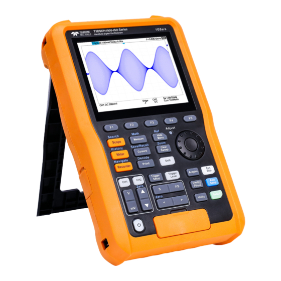
- Page 1 T3DSOH1000 and T3DSOH1000-ISO Handheld Oscilloscope User Manual...
-
Page 2: Copyright Information
Declaration © 2023 Teledyne LeCroy, Inc. All rights reserved. Teledyne Test Tools is a brand and trademark of Teledyne LeCroy, Inc. Other product or brand names are trademarks or requested trademarks of their respective holders. Specifications, prices, availability and delivery subject to change without notice. -
Page 3: Table Of Contents
Contents COPYRIGHT INFORMATION ......................1 GENERAL SAFETY SUMMARY ......................4 SAFETY TERMS AND SYMBOLS ..................... 6 MEASUREMENT CATEGORY DEFINITIONS ................... 6 WORKING ENVIRONMENT ......................11 GENERAL CARE AND CLEANING ....................12 QUICK START ..........................13 INTRODUCTION OF SCOPE PANEL ....................17 INTRODUCTION OF METER PANEL .................... - Page 4 FACTORY SETUP ........................... 192 TROUBLESHOOTING ........................192 COMPLIANCE INFORMATION ...................... 194 T 3 D S O H 1 0 0 0 / I S O U s e r M a n u a l...
-
Page 5: General Safety Summary
General Safety Summary This document contains information and warnings that must be followed by the user to ensure safe operation and to keep the instrument in a safe condition. Use of this equipment in a manner not specified by the manufacturer may impair protection provided by the equipment. - Page 6 If the battery leaks, do not let the liquid contact the skin or eyes. If contact occurs, wash the contact area with plenty of water and seek medical assistance. • Use the power adapter specified by Teledyne Test Tools. • Charge the product in a well-ventilated room. Ensure the product is not covered by objects (such as blankets, towels, clothes) during charging, which will affect the heat dissipation effect and cause a serious fire.
-
Page 7: Safety Terms And Symbols
Safety Terms and Symbols The meaning of symbols symbol meaning symbol meaning Warning Power Switch Equipment meeting double Hazardous Voltage insulation or reinforced insulation Earth Ground Indoor use only EU label for separately Lithium battery failure recycled electrical and electronic equipment Measurement Category Definitions IEC61010-2-030 defines the measurement category to rate the ability of measuring instruments to withstand short-term transient overvoltage outside of the working voltage. - Page 8 T3DSOH1000 Measurement Category T3DSOH1000 can work under the measurement category listed in the table below. Observe all voltage and current ratings of the instrument, the probes, and the accessories. The lowest rated component defines the rating of the complete measurement setup. T3DSOH1000 Max Input Voltage CAT II 300Vrms Between BNC Signal and BNC GND.
- Page 9 Probe Input BNC Input INPUT B INPUT A CAT II 300V CAT II 300V System GND CAT II 30V CAT II 30V Protecting GND Protective Earth Measurement Category for T3DSOH1000 Scope Multimeter Meter Input Input Ω CAT III 300V CAT II 600V CAT III 300V CAT III 300V CAT II 600V...
- Page 10 T3DSOH1000-ISO Measurement Category T3DSOH1000-ISO can work under the measurement category listed in the table below. Observe all voltage and current ratings of the instrument, the probes, and the accessories. The lowest rated component defines the rating of the complete measurement setup. T3DSOH1000-ISO Max Input Voltage CAT III 300Vrms Between BNC Signal and BNC GND.
- Page 11 Probe Input BNC Input INPUT A INPUT B CAT III 600V CAT III 300V /CAT II 1000V GND A GND B CAT III 600V CAT III 600V /CAT II 1000V /CAT II 1000V Protecting GND Protective Earth Measurement Category for T3DSOH1000-ISO Scope Multimeter Input Protective Earth...
-
Page 12: Working Environment
Working Environment General requirement Environment This product is intended for indoor use and should be operated in a clean, dry environment. It can be stored in a waterproof/dustproof environment rated up to IP51. Temperature Operating: 0℃ to +40℃ Not operating:-20℃ to +60℃ Note: Direct sunlight, radiators, and other heat sources should be taken into account when assessing the ambient temperature. -
Page 13: General Care And Cleaning
AC Power Requirement The power adapter operates with a single-phase, 100 to 240 Vrms (+/-10%) AC power at 50/60 Hz (+/-5%). Depending on the type and number of options and accessories (probes, PC port plug- in, charging etc.), When powered by adapter, the product can consume up to 35 W of power. -
Page 14: Quick Start
Quick Start Product Appearance T3DSOH1000 T3DSOH1000-ISO T3DSOH1000/ISO User Manual... - Page 15 Battery Installation To protect the battery from over discharging, the battery may be delivered separately. Please install the battery before use as follows: 1. Remove the three screws on the battery cover with a screwdriver, as shown in Figure 2. Remove the battery cover, as shown in Figure 2. 3.
- Page 16 Measurement Connection The T3DSOH1000 and T3DSOH1000-ISO series handheld oscilloscope measurement accessories include oscilloscope probes, multimeter probes, current adapters. 1. Oscilloscope probe All oscilloscope probes should be properly compensated before their first use with the oscilloscope. The following steps illustrate the proper probe compensation procedure. 1) Connect probe to the CH1 Input Terminal and the Compensation Signal Output Terminal on the right side panel.
- Page 17 2. Multimeter probe Before using the multimeter probe, please select the measuring range of the multimeter first, then plug the red probe and black (grounding terminal) probe into the corresponding input terminals according to the marking prompt of the front panel. When measuring the current, please select the correct accessories according to the current.
-
Page 18: Introduction Of Scope Panel
Introduction of Scope Panel LCD Display Trigger Control Menu Softkey Single function Control Buttons Multifunction Control Buttons Power Button Universal Knob Multimeter Inputs Vertical Control Oscilloscope Analog Inputs Horizontal Control T3DSOH1000/ISO User Manual... - Page 19 Vertical Control Analog channel on/off or channel is selected to change. Push to increase the vertical scale of selected channel Push to decrease. Push to increase the vertical offset of selected channel Push to decrease. When is lit, press to set offset to zero quickly. Horizontal Control Push to increase the timebase Push to decrease...
- Page 20 Introduction of Multi function Menu Button Description Shift Press to illuminate the button light, and then by pressing the multifunction button one can activate the alternate function shown above the function button. When the shift light is off, press these buttons to enter/exit the following functions. Scope Push this button to enter the scope mode.
- Page 21 Math This menu provides various math operation which includes adding, subtracting, multiplying, dividing, FFT, integral, differential and square root. Save/Recall Save and recall function. The storable file types include Setups, Reference Waveforms, Picture, CSV and File Converter tool. Recallable file types include setup and reference waveform files. Decode Supports two serial buses including 1 and 2 for analog signal decoding.
- Page 22 Scope User Interface Channel label/waveform, different channels are marked with different colors, the color of the waveform is consistent with the color of the channel. Measure waveform. Working state, including Arm, Ready, Trig’d, Stop, FStop, Auto and Roll. Horizontal time base, indicating the duration of each grid is 200us. Delay, the time of the screen center position relative to the waveform trigger position.
-
Page 23: Introduction Of Meter Panel
Introduction of Meter Panel Meter Button Universal Knob Hold Button Menu Softkey T3DSOH1000/ISO User Manual... - Page 24 Introduction of Function Menus Button Description Meter Button Press to enter multimeter mode. F1~F5 Press to activate Relative, Auto Range, Manual Range, Measurement logger function. Universal Press to switch measurement ranges in manual mode. Use the knob Knob to quickly switch between ranges and meter functions. Run/Stop Press the Run/Stop button to stop the meter measurement.
-
Page 25: Introduction Of Recorder Panel
Introduction of Recorder Panel Recorder Button Universal Knob Menu Softkey Introduction of Function Menus Button Description Recorder Button Press to enter Recorder mode. F1~F5 Press to activate sample logger or measurement logger. Universal Knob Use the knob to quickly select the recorder interval in measurement logger and sample logger mode. - Page 26 Sample Logger User Interface Channel label/waveform, different channels are marked with different colors, the color of the waveform is consistent with the color of the channel. Waveform of samples. Recorder status. Stop indicates stop recording,Run indicates it is recording. Indicate that each time grid is 16s. Indicates how long it took to record data.
- Page 27 Measure Logger User Interface Trend chart display area: Four parameters can be recorded at the same time. The current status of the recorder: Stop means stop recording, and Run means recording. Indicates that the length of each grid is 10s. The length of time the starting point is relative to the reference position.
-
Page 28: Interface Glance
Interface Glance The Right Side Panel USB Device: Connects with a PC for remote control USB Host Port Probe Compensation / Ground Terminal Hand strap installation slot The Left Side Panel Hand strap installation slot Charging Interface T3DSOH1000/ISO User Manual... -
Page 29: Vertical System
Vertical System Introductory on how to set the vertical system of the handheld oscilloscope. Enable the Channel The T3DSOH1000/T3DSOH1000-ISO provides 2 analog input channels and each channel shares the same vertical control system. Since the vertical system setting methods of each channel is the same, this chapter uses CH1 as an example to introduce the setting method of the vertical system. - Page 30 desired mode. Press the Vertical Scale button to adjust the vertical scale (V to increase the scale and mV to reduce). The scale information in the channel information bar at the bottom of the screen will change accordingly during the adjustment process. The adjustable range of the vertical scale is related to the probing ratio currently set.
- Page 31 Universal Knob to select the desired coupling mode. The default setup is DC. The current coupling mode is displayed in the channel information bar at the bottom of the screen. You can also press the Coupling softkey continuously to switch the coupling mode.
- Page 32 The table shows the probe attenuation factor: Menu Attenuation Factor 0.1X 0.1 : 1 0.2X 0.2 : 1 0.5X 0.5 : 1 1 : 1 2 : 1 … … 5000X 5000 : 1 10000X 10000 : 1 Custom 1000000:1~0.000001:1 You can also customize the probe attenuation factor.
- Page 33 Deskew The valid range of each analog channel is ±100ns. Press CH1 button on the front panel to enter the CH1 function menu. Press the Next Page softkey to enter the second page of the CH1 function menu. Press the Deskew softkey. Then turn the Universal Knob to change deskew. Invert When Invert is set to On, the voltage values of the displayed waveform are inverted.
- Page 34 Trace Visible Trace Hidden T3DSOH1000/ISO User Manual...
-
Page 35: Horizontal System
Horizontal System Introductory on how to set the horizontal system of the handheld oscilloscope. Horizontal Scale Press the Horizontal Scale button on the front panel to adjust the horizontal time base. Press the ns to decrease the horizontal time scale and press the s to increase. The time base information at the upper left corner of the screen will change accordingly during the adjustment. - Page 36 Roll Mode Press the Acquire button to enter the acquire menu and press the Roll Mode softkey to enable the roll mode. In Roll mode the waveform moves slowly across the screen from right to left. It only operates on time base settings of 50 ms/div or slower. In Roll mode there is no trigger.
- Page 37 Split Screen Zoom The extended normal window area is outlined with a border, and the rest of the normal window is ghosting. This border area in the normal window is zoomed to the lower half. To change the time base for the Zoom window, press the Horizontal Scale button. The Horizontal Scale button controls the size of the border area.
-
Page 38: Acquisition System
Acquisition System Introductory on how to use the acquisition control and set the sampling system of the handheld oscilloscope. Overview To understand the oscilloscope's sampling and acquisition modes, it is helpful to understand sampling theory, sample rate and oscilloscope bandwidth and sample rate. Sampling Theory The Nyquist sampling theorem states that for a limited bandwidth (band- limited) signal with maximum frequency f... - Page 39 The effect of low sampling rate on the waveform: Waveform Distortion: when the sample rate is too low, some waveform details are lost and the waveform displayed is quite different from the actual signal. Waveform Confusion: when the sample rate is lower than twice the actual signal frequency (Nyquist Frequency), the waveform frequency reconstructed from the sample data is lower than the actual signal frequency.
- Page 40 Bandwidth and Sample Rate An oscilloscope's bandwidth is typically described as the lowest frequency at which the input sinusoidal signal is attenuated by 3 dB (- 30% amplitude error). Under the bandwidth frequency, the required sampling rate is f = 2f according to the sampling theory.
- Page 41 Therefore, the sampling frequency of the oscilloscope should be four or more times the bandwidth frequency: f = 4fBW. In this way, there is less aliasing, and the components in the aliasing area are attenuated a lot. Memory Depth Memory depth refers to the number of waveform points that the oscilloscope can store in a single trigger sample and it reflects the storage ability of the sample memory.
- Page 42 The maximum storage depth in single channel mode is twice that in dual channel mode, as shown in the following table: Single Channel Mode Dual Channel Mode 120k 1.2M 600k The relation of memory depth, sample rate, and waveform length fulfills the equation below: Memory depth = sample rate (Sa/s) ×...
- Page 43 Press the Acquire button on the front panel to enter the ACQUIRE Function menu; then press the Interpolation softkey to select Sinx/x or X. • X: In the adjacent sample points are directly connected on a straight line. This method is only confined to rebuild on the edge of signals, such as a square wave. •...
- Page 44 x Interpolation Sinx/x Interpolation T3DSOH1000/ISO User Manual...
- Page 45 Acquisition Mode The acquisition mode is used to control how to generate waveform points from sample points. The oscilloscope provides the following acquisition mode: Normal, Peak Detect, Average, and ERES. 1. Press the Acquire button on the front panel to enter the ACQUIRE function menu; 2.
- Page 46 Peak Detect In this mode, the oscilloscope acquires the maximum and minimum values of the signal within the sample interval to get the signal's envelope or the narrow pulse of the signal that might be lost. In this mode, signal confusion can be prevented but the noise displayed would be larger.
- Page 47 Pulse With 0.1% Duty, Peak Detect Mode Average In this mode, the oscilloscope averages the waveforms from multiple samples to reduce the random noise of the input signal and improve the vertical resolution. The greater the number of averages is, the lower the noise and the higher the vertical resolution will be. Still, the slower the response of the displayed waveform to the waveform changes will The available range of averages is from 4 to 1024 and the default is 16.
- Page 48 With Random Noise, Normal Mode With Random Noise, Average Mod T3DSOH1000/ISO User Manual...
- Page 49 ERES This mode uses a kind of ultra-sample technique to average the neighboring points of the sample waveform to reduce the random noise on the input signal and generate much smoother waveforms on the screen. ERES mode is generally used when the sample rate of the digital converter is higher than the storage rate of the acquisition memory.
- Page 50 The phase deviation between two signals with the same frequency can be easily measured via Lissajous method. The figure below shows the measurement schematic diagram of the phase deviation. According to sinθ = A/B or C/D (wherein, θ is the phase deviation angle between the two channels and the definitions of A, B, C, and D are as shown in the figure above), the phase deviation angle is obtained, that is: θ...
- Page 51 Sequence Mode Sequence is also a kind of acquisition mode, which does not display waveform during the sampling process. It improves the waveform capture rate, and the maximal capture rate is 400,000 wfs/s. So it can capture the small probability event effectively. The oscilloscope runs and fills a memory segment for each trigger event.
- Page 52 Do the following steps to replay the sequence waveform under history mode: 1. Press the Shift and Meter button to enable HISTORY function. History Function Menu 2. Press the List softkey to turn on the list display. The list records the acquisition time of every frame and shows the frame number that displaying on the screen.
-
Page 53: Trigger
Trigger For trigger, you set certain trigger condition according to the requirement. When a waveform in the waveform stream meets this condition, the oscilloscope captures this waveform and the neighboring part and displays them on the screen. Still, the digital oscilloscope displays waveform continuously no matter whether it is stably triggered, but only stable trigger can ensure stable display. - Page 54 Trigger Source Press the Trigger Setup button on the front panel to enter the TRIGGER function menu; press the Source softkey and then turn the Universal Knob to select the desired trigger source. The current trigger source is displayed at the bottom of the screen. Select channel with signal input as trigger source to obtain stable trigger.
- Page 55 The Auto trigger mode is appropriate when: • Checking DC signals or signals with unknown levels or activity. • When trigger conditions occur often enough that forced triggers are unnecessary. ➢ In the Normal trigger mode, triggers and acquisitions only occur when the specified trigger conditions are found.
- Page 56 Trigger Level Trigger level and slope define the trigger point, You can adjust the trigger level for a selected analog channel by pressing the Trigger Level button and turning the Universal Knob. You can push the Universal Knob to set the level to the waveform's 50% value immediately.
- Page 57 Trigger Coupling Press the Trigger Setup button on the front panel to enter the TRIGGER function menu. Then, press the Coupling softkey and turn the Universal Knob or press the Coupling softkey continually to select the desired coupling mode. The oscilloscope provides 4 kinds of trigger coupling modes: •...
- Page 58 The correct holdoff setting is typically slightly less than one repetition of the waveform. Set the holdoff to this time to generate a unique trigger point for a repetitive waveform. Only edge trigger and serial trigger have holdoff option. The holdoff time of the oscilloscope is adjustable from 80ns to 1.5s.
- Page 59 Noise Rejection Noise Reject adds additional hysteresis to the trigger circuitry. By increasing the trigger hysteresis band, you reduce the possibility of triggering on noise. However, this also decreases the trigger sensitivity so that a slightly larger signal is required to trigger the oscilloscope.
- Page 60 Turn on the Noise Reject If the signal you are probing is noisy, you can set up the oscilloscope to reduce the noise in the trigger path and on the displayed waveform. First, stabilize the displayed waveform by removing the noise from the trigger path. Second, reduce the noise on the displayed waveform.
-
Page 61: Trigger Type
Trigger Type The oscilloscope provides abundant advanced trigger functions, including various serial bus triggers. • Edge trigger • Slope trigger • Pulse trigger • Video trigger • Window trigger • Interval trigger • Dropout trigger • Runt trigger • Pattern trigger T3DSOH1000/ISO User Manual... - Page 62 Edge Trigger Edge trigger distinguishes the trigger points by seeking the specified edge (rising, falling, alternating) and trigger level. 1. Press the Trigger Setup button on the front panel to enter the TRIGGER system function menu. 2. Press the Type softkey; turn the Universal Knob to set select Edge and then push the knob to confirm.
- Page 63 Edge Trigger Holdoff, coupling and noise reject can be set in edge trigger, see the sections “Trigger Holdoff”, "Trigger Coupling" and "Noise Rejection" for details. *Note: Press the Auto Setup button will set the trigger type to Edge and slope to rising. T3DSOH1000/ISO User Manual...
- Page 64 Slope Trigger The slope trigger looks for a rising or falling transition from one level to another level in greater than or less than a certain amount of time. In the oscilloscope, positive slope time is defined as the time difference between the two crossing points of trigger level line A and B with the positive edge as shown in the figure below.
- Page 65 Slope Trigger 1. Press the Limit Range softkey; then turn the Universal Knob to select the desired slope condition, and push down the knob to confirm. • <= (less than a time value): trigger when the input signal's positive or negative slope time is lower than the specified time value. •...
- Page 66 Pulse Trigger Trigger on the positive or negative pulse with a specified width. 1. Press the Trigger Setup button on the front panel to enter the TRIGGER function menu. 2. Press the Type softkey; turn the Universal Knob to select Pulse and then push the knob to confirm.
- Page 67 • [--,--] (within a range of time value):trigger when the input signal's positive or negative pulse time is greater than the specified lower limit of time and lower than the specified upper limit of time value. For example, for a positive pulse, if you set t (pulse real width) ≥100ns and t ≤...
- Page 68 Video Trigger Video triggering can be used to capture the complicated waveforms of most standard analog video signals. The trigger circuitry detects the vertical and horizontal interval of the waveform and produces triggers based on the video trigger settings you have selected.
- Page 69 The table below shows the parameters of the Custom video trigger. Frame Rate 25Hz, 30Hz, 50Hz, 60Hz Of Lines 300~2000 Of Fields 1, 2, 3, 4 Interlace 1:1, 2:1, 4:1, 8:1 Trigger Position Line Field (line value)/1 (line value)/2 (line value)/3 (line value)/4 (line value)/5 (line value)/6...
- Page 70 The following table lists the line numbers per field for each video standard. Standard Field 1 Field 2 NTSC 1 to 262 1 to 263 1 to 312 1 to 313 HDTV 720P/50, HDTV 720P/60 1 to 750 HDTV 1080P/50, HDTV 1080P/60 1 to 1125 HDTV 1080iP/50, HDTV 1080i/60 1 to 562...
- Page 71 Video Trigger To Use Custom Video Trigger Custom video trigger supports frame rate of 25Hz, 30Hz, 50Hz and 60Hz, and the line range is available from 300 to 2000. The steps below show how to set custom trigger. 1. Press the Trigger Setup button on the front panel to enter the TRIGGER function menu.
- Page 72 Window Trigger Windows trigger provides a high trigger level and a low trigger level. The instrument triggers when the input signal passes through the high trigger level or the low trigger level. There are two kinds of window types: Absolute and Relative. They have different trigger level adjustment methods.
- Page 73 The Lower trigger level cannot be greater than the upper trigger level. Absolute Window Trigger To set window trigger via Relative window type: 1. Press the Trigger Setup button on the front panel to enter the TRIGGER system function menu. 2.
- Page 74 Relative Window Trigger Coupling and noise reject can be set in Window trigger, see the sections "Trigger Coupling" and "Noise Rejection" for details. T3DSOH1000/ISO User Manual...
- Page 75 Interval Trigger Trigger when the times difference between the neighboring rising or falling edges meets the time limit (<=, >=, [--,--], --][--). To set interval trigger: 1. Press the Trigger Setup button on the front panel to enter the TRIGGER system function menu.
- Page 76 Interval Trigger Coupling and noise reject can be set in interval trigger, see the sections "Trigger Coupling" and "Noise Rejection" for details. T3DSOH1000/ISO User Manual...
- Page 77 Dropout Trigger Dropout trigger includes two types: edge and state. Edge Trigger when the time interval (△T) from when the rising edge (or falling edge) of the input signal passes through the trigger level to when the neighboring rising edge (or falling edge) passes through the trigger level is greater than the timeout time set, as shown in the figure below.
- Page 78 3. Press the Source softkey; turn the Universal Knob to select CH1 or CH2 as the trigger source. The current trigger source is displayed at the upper right corner of the screen. Select channel with signal input as trigger source to obtain stable trigger. 4.
- Page 79 State Dropout Trigger Coupling and noise reject can be set in dropout trigger, see the sections "Trigger Coupling" and "Noise Rejection" for details. T3DSOH1000/ISO User Manual...
- Page 80 Runt Trigger The Runt trigger looks for pulses that cross one threshold but not another as shown in the picture below. • A positive runt pulse crosses through a lower threshold but not an upper threshold. • A negative runt pulse crosses through an upper threshold but not a lower threshold.
- Page 81 Runt Trigger Coupling and noise reject can be set in runt trigger, see the sections "Trigger Coupling" and "Noise Rejection" for details. T3DSOH1000/ISO User Manual...
- Page 82 Pattern Trigger The Pattern trigger identifies a trigger condition by looking for a specified pattern. The pattern trigger can be expanded to incorporate delays similar to other triggers. Pattern durations are evaluated using a timer. The timer starts on the last edge that makes the pattern “true”.
- Page 83 pressing the Trigger Level button and turning the Universal Knob. Don’t care doesn’t need to set trigger level. 4. Press the Next Page softkey to enter the second page of the pattern trigger menu. 5. Press the Logic softkey and then turn the Universal Knob to select the desired logic combination AND, OR, NAND or NOR.
-
Page 84: Serial Trigger And Decode
Serial Trigger and Decode The oscilloscope provides I2C, SPI, UART, CAN and LIN serial trigger and decode. This chapter introduces the method of triggering and decoding these serial signals in details. • I2C Trigger and Decode • SPI Trigger and Decode •... - Page 85 I2C Trigger and Serial Decode Setup for I2C Signals Setting the I2C (Inter-IC bus) signal includes two steps: connecting the serial data signal (SDA) and serial clock signal (SCK) to oscilloscope, specifying the threshold voltage of each input signal. 1. Press the Shift and Print button to enter the DECODE function menu as the image shown below.
- Page 86 (Tips: SDA should keep stable during the whole high clock cycle, otherwise it will be interpreted as a start or stop condition (data transitioning while the clock is high)) softkey to return previous menu. 7. Press the I2C Trigger This part introduces the nine kinds of trigger conditions (Start, Stop, Restart, No Ack, EEPROM, 7 Addr&Data, 10 Addr&Data and Data Length) and the methods of setting them.
- Page 87 • 7 Address & Data — the oscilloscope will be triggered when the following conditions are satisfied. The address’s length must be 7 bits and the address’s value is the same as set value. If you have set either Data1’s or Data2’s value, and the signal has a data is the same as that value.
- Page 88 The address’s length must be 10 bits and the address’s value is the same as set value. If you have set either Data1’s or Data2’s value, and the signal has a data is the same as that value. If you have set both Data1’s and Data2’s value, the signal should has two consecutive data, the first data’s value is Data1, second data value is Data2.
- Page 89 • If you select the EEPROM condition: Press the Limit Range softkey to set the qualifier (=, < or >). Press the Data1 softkey and set its value by turning the Universal Knob. • If you select 7 Addr & Data or 10 Addr & Data condition: Press the Addr softkey and turn the Universal Knob to select the 7- bit or 10- bit device address.
- Page 90 I2C Serial Decode After completing the setup of I2C signal and trigger, we will decode I2C signals. Operation steps as follows. 1. Press Shift and Print→ Decode. Select one of the options from the Decode1 and Decode2. 2. Press the Display and select On to display the result of decoding. 3.
- Page 91 Interpreting I2C Decode The frames of decoding result: • The address value is displayed at the beginning of a frame. The write address is displayed in green, and read address in yellow. • W/R bit is represented by (W) and (R), following the address value. •...
- Page 92 SPI Trigger and Serial Decode Setup for SPI Signals Setting the SPI (Serial Peripheral Interface) signal includes two steps: connecting the CLK, MISO, MOSI and CS signals to oscilloscope; specifying the parameters of each input signal. 1. Press the Shift and Print button to enter the DECODE function menu. 2.
- Page 93 MISO Menu Set MOSI: a. Press the MOSI softkey to enter the MOSI menu. b. Press the MOSI softkey to select the channel that is connected to the SPI MOSI signal. c. Press the Threshold softkey to set the SPI MOSI signal’s threshold voltage level by Universal Knob.
- Page 94 Example: Connect the data, CLK signals of a SPI bus respectively to C1, C2. Data width = 8-bit, Bit order = MSB, and 12 bytes are transmitted in one frame. In the SPI trigger signal menu, set the source and threshold of CLK, MISO signals. Set the CS type to Clock Timeout, the clock idle time between frames is T3, the clock period is T1, then set the timeout to a value between T1 and T3:...
- Page 95 SPI Trigger This part will provide a brief introduction and description for the operation of the SPI trigger. 1. Press the Trigger Setup button to enter the TRIGGER function menu. 2. Press the Type and select Serial. 3. Press the Protocol and select SPI. 4.
- Page 96 1. Press the Trigger Type softkey to select the trigger condition. Function Settings Explanation MISO Master-In, Slave-Out Trigger Menu Type MOSI Master-Out, Slave-In Menu Explanations of the SPI trigger type 2. Press the Data Length softkey, and turn the Universal Knob to set the length of a data.
- Page 97 SPI Serial Decode After completing the setup of SPI signal and trigger, we will decode SPI signals. Operation steps as follows. 1. Press Shift and Print → Decode. Select one of the options from the Decode1 and Decode2. 2. Press the Configure to set the bit stream format and bits (4-32 bits) 3.
- Page 98 Interpreting SPI Decode The frames of decoding result: • The data values are displayed in frames and are shown in white. Support 4~96 bit data display. • MISO — the decoding result of “Master-In, Slave-Out” line. • MOSI —the decoding result of “Master-Out, Slave-In” line. •...
- Page 99 UART Trigger and Serial Decode Setup for UART Signals 1. Press the Shift and Print button to enter the DECODE function menu. 2. Press the Decode softkey and select the desired slot (Decode1 or Decode2). 3. Press the Protocol softkey and then select UART by turning Universal Knob. 4.
- Page 100 Press the Baud softkey to set baud rate. a. The baud rate can be set as predefined value. b. If the desired baud rate is not listed, press the Baud and select custom option, press the Custom and turn the Universal Knob to set the desired baud rate. Press the Data Length softkey and set byte bits (5-8) by Universal Knob.
- Page 101 UART Trigger This part shows a brief introduction and description for the operation of the UART trigger. 1. Press the Trigger Setup button to enter the TRIGGER function menu. 2. Press the Type and select Serial. 3. Press the Protocol and select UART. 4.
- Page 102 UART Serial Decode After completing the setup of UART signal and trigger, we will decode UART signals. Operation steps as follows. 1. Press Shift and Print → Decode. Select one of the options from the Decode1 and Decode2. 2. Press the Display and select On to display the result of decoding. 3.
- Page 103 Interpreting UART Decode The frames of decoding result: • RX — the decoding result of the data received. • TX — the decoding result of the data transmitted. • Indicates there is not enough space on the display to show the complete content of a frame, and some content is hidden.
- Page 104 CAN Trigger and Serial Decode Setup for CAN Signals 1. Press the Shift and Print button to enter the DECODE function menu. 2. Press the Decode softkey and select the desired slot (Decode1 or Decode2). 3. Press the Protocol softkey and then select CAN by turning Universal Knob. 4.
- Page 105 CAN Trigger This part will provide a brief introduction and description for the operation of the CAN trigger. Trigger Conditions • Start— the oscilloscope will be triggered at the start bit of a frame. • Remote — the oscilloscope will be triggered by a remote frame with specified ID. •...
- Page 106 CAN Serial Decode After completing the setup of can signal and trigger, we will decode CAN signals. Operation steps as follows. 1. Press Shift and Print → Decode. Select one of the options from the Decode1 and Decode2. 2. Press the Display and select On to display the result of decoding. 3.
- Page 107 Interpreting CAN Decode. The frame of decoding result: • Arbitration field is displayed in frame • Control field is displayed in frame • Data field is displayed in frame • CRC field is displayed in frame • Indicates there is not enough space on the display to show complete content of a frame and some content is hidden.
- Page 108 LIN Trigger and Serial Decode Setup for LIN Signals There are two steps of setting the LIN signal, connecting the signal to oscilloscope, and specifying each input signal's parameters. 1. Press the Shift and Print button to enter the DECODE function menu. 2.
- Page 109 LIN Trigger This part will provide a brief introduction and description for the operation of the LIN trigger. Trigger Conditions • Break — the oscilloscope will be triggered at the position of break field’s break delimiter. • ID (Frame ID) — the oscilloscope will be triggered at the position of identifier field’s stop bit, if the value of a frame’s ID is equal to specified value.
- Page 110 Operation Steps Press the Trigger Setup button to enter the TRIGGER function menu. Press the Type and select Serial. Press the Protocol and select I2C. Press the Trigger Setting softkey to enter LIN TRIG SET menu. Press the Condition and select the trigger condition by Universal Knob: •...
- Page 111 Interpreting LIN Decode The frame of decoding result: • Protected Identifier Field is displayed in frame • Data Length is displayed in frame • Data Field is displayed in frame. • Checksum Field is displayed in frame. • Indicates there is not enough space on the display to show complete content of a frame and some content is hidden LIN Decode Bus Display The list of decoding result:...
-
Page 112: Reference Waveform
Reference Waveform The oscilloscope can save the analog channel waveform or math waveform to the reference waveform position in the oscilloscope. Then, a reference waveform can be displayed and compared against other waveforms. All reference waveforms can be displayed at the same time. •... - Page 113 Save REF Waveform to Internal Memory Do the following steps to save the REF waveform to internal memory: 1. Press the Shift and Hide Menu button on the front panel to enter the REF WAVE function menu. Note that when the time horizontal format is in X-Y mode, REF function cannot be enabled.
- Page 114 Adjust REF Waveform 1. Please refer to the “Display REF Waveform” above to display the desired reference waveform. 2. Press the Scale and Position softkey and turn the Universal Knob to adjust the vertical scale and position of the reference waveform. The vertical scale and position information display at the middle of the screen.
-
Page 115: Math
Math The oscilloscope supports many math operations between analog channels including addition (+), subtraction (-), multiplication (*), division (/), FFT, differential (d/dt), integral (∫dt), square root (√). The resulting math waveform is displayed in white and labeled with “M”. You can use cursors to measure it. •... - Page 116 Addition or Subtraction Math operators perform arithmetic operations add or subtract operation on any two analog input channels. When you select addition or subtraction, the Source A and Source B values are added or subtracted point by point, and the result is displayed. 1.
- Page 117 Multiplication and Division Math operators perform arithmetic operations multiplication or division operation on any two analog input channels. When you select multiplication or division, the Source A and Source B values are multiplied or divided point by point and the result is displayed. 1.
- Page 118 FFT Operation FFT is used to compute the fast Fourier transform using analog input channels. FFT takes the digitized time record of the specified source and transforms it to the frequency domain. When the FFT function is selected, the FFT spectrum is plotted on the oscilloscope display as magnitude in dBV versus frequency.
- Page 119 • Press the Window softkey, and then turn the Universal Knob to select an appropriate window. Spectral leakage can be considerably decreased when a window function is used. The oscilloscope provides five windows (Rectangle, Blackman, Hanning, Hamming and Flattop) which have different characteristics and are applicable to measure different waveforms.
- Page 120 • Press the Mode softkey to select Normal, Max-Hold or Average. When you select Average, it is necessary to set the average times. 5. Press the Vertical softkey to enter VERTICAL menu. VERTICAL Menu • Press the Scale softkey, and then turn the Universal Knob to select the desired vertical FFT scale •...
- Page 121 • Press the Show Table softkey to display a table of peak, and press Show Frequency softkey to display the frequency value of the peak. Press the Sort By softkey continuously to set the table sorting by Amplitude or Frequency. •...
- Page 122 • Press the Frequency softkey to set the frequency value of the selected marker. • Press the Next Peak softkey to move the selected mark to the next peak. And press the Next Amplitude softkey to move the selected marker to the next peak with lower amplitude.(Up to 20 peaks are supported) •...
- Page 123 *Note: • Signals with DC components or deviation would cause error or deviation of the FFT waveform components. To reduce the DC components, set the Channel Coupling to AC. • To reduce the random noise and aliasing frequency components of repetitive or single pulse, set the Acquisition of the oscilloscope to Average.
- Page 124 Differentiate d/dt (differentiate) calculates the discrete time derivative of the selected source. Where: • d = differential waveform • y = voltage value of data point • i = data point index • dx = point- to- point time difference The dx option under d/dt math function operation menu indicates data points.
- Page 125 You can use differentiate to measure the instantaneous slope of a waveform. For example, the slew rate of an operational amplifier may be measured using the differentiate function. *Note: Because differentiation is very sensitive to noise, it is helpful to set acquisition mode to Average.
- Page 126 Integral without Offset Integral with Offset T3DSOH1000/ISO User Manual...
- Page 127 Square Root Square root ( ) calculates the square root of the selected source. Where the transform is undefined for a particular input, holes (zero values) appear in the function output. Square Root T3DSOH1000/ISO User Manual...
-
Page 128: Cursors
Cursors Cursors are horizontal and vertical markers that indicate X- axis values and Y- axis values on a selected waveform source. You can use cursors to make custom voltage, time measurements on oscilloscope signals. X Cursors X cursors are vertical dashed lines that adjust horizontally and can be used to measure time (when the source is FFT waveform, X cursors measure frequency). - Page 129 Y2 cursor is the down (default position) horizontal dotted line; it can be moved to any vertical place of the screen. Use the Universal Knob to set the Y1 and Y2 cursor values and the values are displayed in the cursors box in the top left corner of the screen along with the difference between Y1 and Y2 (△Y).
- Page 130 Cursor examples: Use cursors to measure pulse width: Measure Pulse Width T3DSOH1000/ISO User Manual...
-
Page 131: Measure
Measure The oscilloscope provides measurements of 38 waveform parameters and the statistics. It contains voltage, time and delay parameters. Voltage and time parameters are under Type option. The results of the last four selected measurements are displayed at the bottom of screen and above the menu. Delay parameters are under the All Measure submenu. - Page 132 Type of Measurement Voltage Measurements Voltage measurements include 17 kinds of voltage parameter measurements. Voltage Measurements 1. Peak-Peak: Difference between maximum and minimum data values. 2. Maximum: Highest value in input waveform. 3. Minimum: Lowest value in input waveform. 4. Amplitude: Difference between top and base in a bimodal signal, or between max and min in a unimodal signal.
- Page 133 Overshoot 14. Preshoot: Preshoot is distortion that precedes a major edge transition expressed as a percentage of Amplitude. The X cursors show which edge is being measured (edge closest to the trigger reference point). Preshoot 15. Level@X: the voltage value between the trigger point and the vertical position of the channel T3DSOH1000/ISO User Manual...
- Page 134 Time Measurements Time measurements include 11 kinds of time parameter measurements. Time Measurements Period: Period for every cycle in waveform at the 50% level, and positive slope. Frequency: Frequency for every cycle in waveform at the 50% level ,and positive slope + Width: Width measured at 50% level and positive slope.
- Page 135 Delay Measurements Delay measurements measure the time different between arbitrary two channels, including 10 kinds of delay measurements. 1. Phase: Calculate the phase difference between two edges. 2. FRFR: Time between the first rising edges of the two channels. 3. FRFF: Time from the first rising edge of channel A to the first falling edge of channel B.
- Page 136 Add Measurement Perform the steps below and select voltage or time parameters to make automatic measurement. 1. Press the Measure button on the front panel to enter the MEASURE function menu. At the same, the frequency and period are enabled with the current trigger channel, the statistics also was enabled.
- Page 137 Added the Measurement *Note: if the parameter does not match the measure condition, it will display as “****”. Clear Measurement Press the Clear softkey to clear all the measurement parameters that are displaying on the screen. All Measurement All measurement could measure all the voltage and time parameters of the current measurement source and display the results on the screen.
- Page 138 All Parameters Measurement Do the following steps to make all parameters measurement. Press the Measure button on the front panel to enter the MEASURE function menu. Press the All Measure softkey to select On. Press the Source softkey to select the measure source. Gate Measurement The T3DSOH1000/T3DSOH1000-ISO support gate measurement and perform the selected measurement within the upper and lower limits of the gate.
- Page 139 Gate Measurement T3DSOH1000/ISO User Manual...
-
Page 140: Display
Display You can set the display type, color, persistence, grid type, waveform intensity, grid brightness and transparence. • Display Type • Color Grade • Persistence • Clear Display • Grid Type • Intensity • Grid Brightness • Transparence • LCD Light T3DSOH1000/ISO User Manual... - Page 141 Display Type Press the Display/Persist button on the front panel, and then press the Type softkey to select Vectors or Dots display type. • Vectors: the sample points are connected by lines and displayed. Normally, this mode can provide the most vivid waveform to view the steep edge of the waveform (such as square waveform).
- Page 142 Dots Display Color Grade Color temperature adopts the change of waveforms’ color to reflect the change of the waveforms’ appearing probability. The greater the probability that the waveform appears, the warmer the color is; the smaller the waveform appears, the colder the color is. The picture below shows the change of color from cold to warm.
- Page 143 Color Temperature Persistence With persistence, the oscilloscope updates the display with new acquisitions, but does not immediately erase the results of previous acquisitions. All previous acquisitions are displayed with reduced intensity. New acquisitions are shown in their normal color with normal intensity.
- Page 144 Persist Set to Infinite 3. When the Persist is On, press the Clear Persist softkey to erase the results of previous acquisitions from the display. The oscilloscope will start to accumulate acquisitions again. 4. To return to the normal display mode, turn off persist and the previous acquisitions will be clear at once.
- Page 145 Grid Type To select grid type 1. Press the Display/Persist button on the front panel to enter the DISPLAY function menu. 2. Press the Next Page softkey to go to the second page of the Display function menu. 3. Press the Grid softkey; and then turn the Universal Knob to select the desired grid type.
- Page 146 Grid Brightness Do the following steps to adjust the grid brightness: 1. Press the Display/Persist button on the front panel to enter the DISPLAY function menu. 2. Press the Next Page softkey to go to the second page of the Display function menu.
-
Page 147: Save And Recall
Save and Recall Oscilloscope setups, waveforms, pictures, and CSV files can be saved to internal oscilloscope memory or to a USB storage device. The saved setups, waveforms can be recalled later. The oscilloscope provides an USB Host interface on the side panel to connect an USB device for external storage. - Page 148 Save Type The oscilloscope supports setups, waveforms, images and CSV files storage. The default save type is setups. 1. Setups It’s the default storage type of the oscilloscope. It saves the settings of the oscilloscope in internal or external memory in “*.xml” format. The stored settings can be recalled. 2.
- Page 149 7. CSV The oscilloscope saves the waveform data in “*.CSV” format. The stored files contain the waveform data of the displayed analog channels and the main setting information of the oscilloscope. The recall of CSV file is not supported. Set the save type to CSV, and set the Param Save option to On or Off to turn on the parameters storage function.
- Page 150 Save file ➢ Save Type Press Shift and Cursors button on the front panel to enter the SAVE/RECALL function menu. Press the Mode softkey to select “Save”. Then press the Type softkey, and turn the Universal Knob to select save type. Press the File Manager softkey to enter the file manager interface, turn the Universal Knob to select the path, and press the Press to Save softkey to save the file.
- Page 151 ➢ Recall file Recall Type Press Shift and Cursors button on the front panel to enter the SAVE/RECALL function menu. Press the Mode softkey to select “Recall”. Then press the Type softkey, and turn the Universal Knob to select recall type. Press the File Manager softkey to enter the file manager interface, and then turn the Universal Knob to select a file (*.xml or *.ref).
- Page 152 File Manager In addition to save and recall files, the file manager also supports the operations of creating, deleting, renaming, copying, cutting and pasting files. File Manager T3DSOH1000/ISO User Manual...
- Page 153 ➢ Create new file and folder The oscilloscope supports English input method. The file name or folder name can contain letters, numbers, underscores and spaces. Example: create a file or folder named “T3DSOH1000_TEST” Press the File Manager softkey to enter the file manager. Press the New softkey to enter the menu.
- Page 154 ➢ Delete file and folder 1. Press the File Manager softkey to enter the file manager. 2. Turn the Universal Knob to select the file or folder to be deleted, and press the Delete softkey. Then the file or folder will be deleted. ➢...
-
Page 155: System Setting
System Setting This function module supports the oscilloscope’s system-related function, such as system status, language, sound, and other advanced settings, such as do self-cal, update and remote interface configure. • View System Status • Do Self Cal • Quick-Cal • Sound •... - Page 156 View System Status Do the following steps to view the system status: 1. Press the Utility button on the front to enter the UTILITY function menu. 2. Press the System Status softkey to view the system status of the oscilloscope. The system status includes the information below: •...
- Page 157 Do Self Cal The self-calibration program can quickly make the oscilloscope reach the best working state to get the most precise measurement values. You can perform self-calibration at any time, especially when the environment temperature change is up to or more than 5 ℃.
- Page 158 Quick-Cal Quick calibration can correct the measurement deviation caused by temperature to get more accurate measurements. If the ambient temperature of your current operating oscilloscope is unstable, press Utility → Quick-Cal softkey to select On to enable quick calibration Sound When the sound is enabled, you can hear the sound of the beeper when you press a function key or a menu softkey or when the prompt message pops up.
- Page 159 Update Firmware and Configuration The firmware and configuration can be updated directly via USB flash driver. Do the following steps to update the firmware: 1. Insert the USB flash driver which with the firmware and the configure files inside into the USB host interface on the side panel of the oscilloscope. 2.
- Page 160 Do Self-Test Self-tests include screen test, keyboard test, and LED test. Self-tests used to test the screen, buttons, knobs and LED lights whether works well. Screen Test 1. Press the Utility button on the front panel to enter the UTILITY function menu. 2.
- Page 161 Keyboard Test Keyboard test is used to test that if the keys or the knobs work well. Do the following steps to do keyboard test: 1. Press the Utility button on the front panel to enter the UTILITY function menu. 2.
- Page 162 LED Test LED test is used to test that if the button lights work well. 1. Press the Utility button on the front panel to enter the UTILITY function menu. 2. Press the Next Page softkey to go to the third page of the UTILITY function menu. 3.
- Page 163 Screen Saver When the oscilloscope enters the idle state and holds for a certain period of time, the screen saver program will be enabled. Do the following steps to set the screen saver time: 1. Press the Utility button on the front panel to enter the UTILITY function menu. 2.
- Page 164 Date/Time T3DSOH1000/ T3DSOH1000-ISO supports setting date and time. After restarting the oscilloscope, you need to reset the system time. 1. Press Utility → NextPage2/3 → Date/Time to enter the DATE/TIME function menu. 2. Press the Display softkey to select On to display the date and time. Date/Time Function Interface Set Date/Time Press the Date/Time softkey to enter the Data/Time setting menu.
- Page 165 Set Time Zone 1. Press the Time Zone softkey to enter the Time Zone function menu, and pop up time zone page. 2. Rotate the Universal Knob to select the time zone. 3. Press the Confirm softkey to confirm the selection. Time Zone Setting Interface T3DSOH1000/ISO User Manual...
- Page 166 Reference Position The reference position setting determines the physical point that the oscilloscope uses during vertical and horizontal scale changes. In some situations, it is more convenient to use a fixed position on the display. Press the Utility button on the front panel and then press the Reference Pos. softkey to enter the Reference POS menu.
-
Page 167: Search
Search T3DSOH1000/ T3DSOH1000-ISO provides search function. This function can search for the events that users specify in the acquired data, the results are displayed with black triangle symbol. In the YT mode or the Roll mode with the acquisition in stop, the maximum search events number is 600. In the Roll mode with acquisition in run, the maximum search events number is unlimited. - Page 168 Search Mode Setting Menu Description Slope includes Rising, Falling, Either. Edge Slope Slope includes Rising, Falling Limit Range includes four types: <=, >=, [--,--] and --] [--, Users can select the desired type and then input the time value. Pulse Polarity includes Positive and Negative Limit Range includes four types: <=, >=, [--,--] and --] [--, Users can select the desired type and then input the time value.
- Page 169 Results When the acquisition is started, “EVENT NUM: 7” means total events number. Search in Run When the acquisition is stop, “EVENT NUM: 4/7” means current event number/total events number, the current event is the closest event to the middle of the screen. T3DSOH1000/ISO User Manual...
- Page 170 Search in Stop Navigate T3DSOH1000/ T3DSOH1000-ISO provides three navigate type: Search Event, Time, History Frame. Time Navigate Press the Shift and Recorder button on the front panel to enter the NAVIGATE function menu. Press the Type softkey In the NAVIGATE function menu, then select Time. There are two ways to navigate time.
- Page 171 History Frame Navigate You can use the navigation controls to play through the acquired frames when the History function is enabled. 1. Press the Shift and Recorder button on the front panel to enter the NAVIGATE function menu. 2. Press the Type softkey in the Navigate Menu, then select History Frame. 3.
- Page 172 stop state. • Press Shift and Meter button again to turn off History function. 2. Press the List softkey to turn on or off the list display. The list records the timestamp of every frame. It is accurate to microseconds. History 3.
- Page 173 Meter This chapter provides a step-by-step introduction to the multimeter functions of T3DSOH1000/ T3DSOH1000-ISO Handheld Digital Oscilloscope. The introduction gives basic examples to show how to use the menus and perform basic operations. The digital multimeter provides the following measurements: DC voltage, AC voltage, resistance, diode, continuity, capacitance, DC current, and AC current.
- Page 174 DCV/ACV The Multimeter enables to measure voltage according to the measurement catalog. When applied in CATII, the maximum input voltage is 1000VDC/ 750VAC for the T3DSOH1000/ T3DSOH1000-ISO series. When applied in CATIII, the maximum input voltage is 600VDC/ VAC for the T3DSOH1000/ T3DSOH1000-ISO series.
- Page 175 DC and AC Function Menu Option Setting Description Save the current input value as a reference and record again. Real value equals relative value plus measurement value Relative Real value equals measurement value Auto(V/mV) Choose the best measurement scale automatically Mode Manual(V/mV) Choose measurement scale manually...
- Page 176 Resistance The method to test resistance will be introduced in details as the following steps. 1. Press Meter to enter multimeter mode, press the F1 softkey to choose Res. measurement. 2. Insert the red probe to the V.Ω.C banana jack input and the black probe to the COM. Connect the other end of probes to the power or load to be measured.
- Page 177 Diode The method to test Diode will be introduced in details as the following steps. 1. Press Meter to enter multimeter mode, press the F1 softkey to choose Diode measurement. 2. Insert the red probe to the V.Ω.C banana jack input and the black probe to the COM. Connect the other end of probes to the diode to be measured.
- Page 178 Continuity Continuity test uses double leads method to measure the resistance of the measured circuit via about 0.2mA current. When the measured resistance in circuit is lower than the selected one, it is considered being connected with instrument. The method to test continuity will be introduced in details as the following steps. 1.
- Page 179 Capacitance The Multimeter enables to measure Capacitance up to 400μF. The method to measure capacitance will be introduced in details as the following steps. 1. Press Meter to enter multimeter mode, press the F1 softkey to choose Cap. measurement. 2. Insert the red probe to the V.Ω.C banana jack input and the black probe to the COM. Connect the other end of probes to the measured object.
- Page 180 DCI/ACI The Multimeter enables to measure DC/AC Current up to 10A by using the accessory SCD10A. The Multimeter enables to measure DC/AC Current up to 600mA by using the accessory SCD600MA . When using the above two accessories, the voltage of the measured circuit shall not exceed 60VDC/ VAC.
- Page 181 DC Current Measurement AC Current Measurement T3DSOH1000/ISO User Manual...
- Page 182 Recorder T3DSOH1000/ T3DSOH1000-ISO supports Sample logger and Measure logger, which can record waveform data and measurement value. Press the Recorder button to enter the RECORDER function menu. Recorder Menu Sample Logger The Sample logger can record the original waveform points in real time at equal intervals to realize the long-time observation of low-speed signals.
- Page 183 Sample Logger Interface Description Recorded waveform Record status(Run/Stop) Horizontal scale Recorded time Remaining recordable time Storage location Sample rate and recorded points of waveform Start time T3DSOH1000/ISO User Manual...
- Page 184 Record Waveform 1. Press the Record softkey to enter the RECORD function menu. 2. Press the Setting softkey to enter the SETTINGS function menu. Press the Rate softkey to set the sampling rate of the waveform. Press the Record to softkey to set the storage location of the recorded data: •...
- Page 185 5. Press the Stop softkey to stop recording, and the record status in the top information bar is displayed as "Stop", the data is automatically stored in the storage location. 6. Press the Recall softkey to look back and analyze the waveform. *Note: When recording to external, the waveform data will be stored to the external in real time.
- Page 186 "How to Extract Data from the Binary File.docx". Please download from TELEDYNE LECROY website. The oscilloscope provides a tool named file converter to convert the waveform file (*.trc) to CSV format. You can download it from the Save/Recall menu.
- Page 187 Measure Logger The Measure logger can record the measured value of waveform in real time to realize the long-time measurement trend observation of low-speed signal. The measurement data is recorded in the internal, and can be stored to the internal or external storage device after stopping recording. It can support up to 4 traces of data at the same time.
- Page 188 Description Record trace Record status(Run/Stop) [Auto/Manual] Horizontal scale [Auto/Manual] Time value of the first point (centered on horizontal reference position) Horizontal reference position Remaining recordable time, Recording interval, Number of recorded points Used memory Recorded time Start time The current value of measurement items Upper and lower scale of the trace Start/Stop Recording 1.
- Page 189 Start to Record Measurement Data 4. Press the Stop softkey to stop recording, the record status in the top information bar is displayed as "Stop". T3DSOH1000/ISO User Manual...
- Page 190 Display Control 1. Press the Display softkey to enter the DISPLAY settings menu. 2. Press the Vertical Scale softkey and turn the Universal Knob to set the vertical scale of the trace. Users can also adjust the scale through the vertical scale button of the channel (mV or V) on the front panel.
- Page 191 d. Press the Track Mode softkey to select the track mode of T-Cursors. • Normal: Track the data at the time of T-Cursors • Maximum: Track the maximum value of the data within a pixel where T-Cursors are located. • Average: Track the average value of the data within a pixel where T-Cursors are located.
- Page 192 Storage Measurement Record 1. Press the Save/Recall softkey to enter the SAVE/RECALL function menu. Save/Recall of Measure Logger 2. Press the Type softkey to select the data type to be saved. The measurement data can be saved as binary data(*.mlg), CSV data or MATLAB data. 3.
- Page 193 Check if the power switch is faulted. Check whether the fuse is burned out. If the fuse needs to be changed, please contact Teledyne LeCroy as soon as possible, to have it repaired by Teledyne LeCroy authorized service personnel. Restart the instrument after completing inspections above.
- Page 194 Make sure the USB disk being used is of flash type, the instrument does not support USB of hardware type. Restart the instrument and then insert the USB to check it. If it is still in abnormal use, please contact with Teledyne LeCroy. 19 3 T3DSOH 1000 /ISO Us er Manual...
- Page 195 Compliance Information This section lists all the applicable Safety, Electromagnetic Compatibility (EMC), and Environmental standards with which the instrument complies as well as the end-of-life handling requirements for proper disposal of the instrument. This product is intended for use by professionals and trained personnel only; it is not designed for use in households or by children.
- Page 196 Nationally Recognized Testing Laboratory (NRTL) Certification TUV marking is a certification mark that indicates that a sample of the product has been independently tested and certified to meet recognized standards for product safety or performance. The product has been certified by TUV SUD to conform to the following safety standards: The product has been certified by TUV SUD to conform to the following IEC, UL and CSA Standards: •...
- Page 197 AUSTRALIA & NEW ZEALAND DECLARATION OF CONFORMITY – EMC The instrument complies with the EMC provision of the Radio Communications Act per the following standards, in accordance with requirements imposed by Australian Communication and Media Authority (ACMA): AS/NZS CISPR 11:2015 Radiated and Conducted Emissions, Group 1, Class A. Australia / New Zealand Contacts:* RS Components Pty Ltd.
- Page 198 The instrument is subject to disposal and recycling regulations that vary by country and region. Many countries prohibit the disposal of waste electronic equipment in standard waste receptacles. For more information about proper disposal and recycling of your Teledyne LeCroy product, please visit teledynelecroy.com/recycle.
- Page 199 有毒有害物质和元素 部件名称 铅 汞 镉 六价铬 多溴联苯 多溴二苯醚 (Pb) (Hg) (Cd) (Cr6+) (PBB) (PBDE) PCBAs 机械硬件 金属片 塑料部件 电缆组件 显示器 电源 风扇 电池 电源线 外部电源(如有) 探头(如有) 熔丝(如有) 产品外壳(如有) 适配器/模块(如有) 鼠标(如有) O: 表明该有毒有害物质在该部件所有均质材料中的含量均在SJ/T11364-2014标准规定的限量要求之下。 X: 表示该有毒有害物质至少在该部件的某一均质材料中的含量超出SJ/T11364-2014标准规定的限量要求。 EFUP (对环境友好的使用时间): 30年。 使用条件:参阅用户手册“环境条件”部分的规定。 探头EFUP: 10年。 T3DSOH1000/ISO User Manual...
- Page 200 Toxic or Hazardous Substances and Elements Polybromina Lead Mercury Cadmium Polybromina Hexavalent Part Name ted Diphenyl Chromium (Pb) (Hg) (Cd) Biphenyls Ethers (Cr6+) (PBDE) (PBB) PCBAs Mechanical Hardware Sheet Metal Plastic Parts Cable Assemblies Display Power Supply Fans Batteries Power Cord Ext Power Supply (if present) Probes (if present)
- Page 201 © 2021 Teledyne Test Tools is a brand and trademark of Teledyne LeCroyInc. All rights reserved.Specifications,prices,availability and deliverysubject to change without notice. Product brand or brand names are trademarks or requested trademarks of their respective holders. T3 stands for Teledyne Test Tools.
Need help?
Do you have a question about the Everywhereyoulook T3DSOH1000 and is the answer not in the manual?
Questions and answers