
Subscribe to Our Youtube Channel
Related Manuals for Teledyne T3DSO2000 Series


Summary of Contents for Teledyne T3DSO2000 Series
- Page 1 User Manual T3DSO2000 Series Digital Oscilloscope 1.800.561.8187 information@itm.com www. .com...
- Page 2 1.800.561.8187 information@itm.com www. .com...
- Page 3 Declaration Teledyne LeCroy products are protected by patent law. Teledyne LeCroy reserves the right to modify or change parts of or all the specifications or pricing policies at company‘s sole decision. Information in this publication replaces all previously corresponding material.
-
Page 4: Safety Information
Safety Information General Safety Summary Carefully read the following safety precautions to avoid any personal injury or damage to the instrument and any products connected to it. To avoid potential hazards, please use the instrument as specified. Use Proper Power Cord Only the power cord designed for the instrument and authorized by local country should be used. - Page 5 If you suspect damage has occurred to the instrument, have it inspected by qualified service personnel before further operation. Any maintenance, adjustment or replacement especially to circuits or accessories must be performed by Teledyne Test Tools authorized personnel. Do Not Operate in Wet Conditions.
-
Page 6: Safety Terms And Symbols
This electronic product is subject to disposal and recycling regulations that vary by country and region. Many countries prohibit the disposal of waste electronic equipment in standard waste receptacles. For more information about proper disposal and recycling of your Teledyne LeCroy product, Terms and Symbols The following symbols appear on the product or in its documentation: WARNING High Voltage. -
Page 7: Measurement Category
Measurement Category Measurement Categories T3DSO2000 series digital oscilloscope’s measurement terminals are not rated for measurements within measurement categories II, III, or IV WARNING Measuring terminals on this product are not intended to be connected directly to mains. Measurement Category Definitions Measurement category II is for measurements performed on circuits directly connected to low voltage installations. -
Page 8: Working Environment
Working Environment Temperature Operating: 10℃ to +40℃ Non-operation:-20℃ to +60℃ Humidity Operating: 85% RH, 40℃, 24 hours Non-operating: 85% RH, 65℃, 24 hours WARNING To avoid short circuit inside the instrument or electric shock, please do not operate in humid environment. Altitude Operating: less than 3 km Non-operation: less than 15 km... -
Page 9: Ventilation Requirement
Ventilation Requirement This oscilloscope uses fan-forced air cooling. Please make sure that the air intake and exhaust areas are free from obstructions and have adequate ventilation. When using the oscilloscope in a bench-top or rack setting, provide at least 10 cm clearance beside, above and behind the instrument for adequate ventilation. -
Page 10: General Care And Cleaning
General Care and Cleaning Care Do not store or leave the instrument in direct sunshine for long periods of time. WARNING To avoid damage to the instrument or probes, please do not leave them in fog, liquid, or solvents. Cleaning Please perform the following steps to clean the instrument and probe regularly according to its operating conditions. -
Page 11: Document Overview
Document Overview This manual introduces how to use the T3DSO2000 series digital oscilloscope in detail. Provides information about preparations before Quick Start using the instrument and a brief introduction of the key instrument features To Set the Vertical System Introduces the functions of the vertical system of... - Page 12 This manual uses the T3DSO2304 in examples and the descriptions shown list all the functions and performances of other models. T3DSO2000 series includes the following models: Model Analogy Bandwidth channels T3DSO2304 300 MHz T3DSO2204 200 MHz T3DSO2104 100 MHz T3DSO2302...
-
Page 13: Table Of Contents
Table of Contents Copyright and Declaration ......................I Safety Information ..........................II General Safety Summary ......................II Safety Terms and Symbols ...................... IV Measurement Category......................V Working Environment ......................VI Ventilation Requirement......................VII General Care and Cleaning....................VIII Document Overview........................IX Quick Start............................1 General Inspection ........................2 Appearance and Dimensions ....................3 To Prepare the Oscilloscope for Use..................4 To Adjust the Supporting Legs ..................4... - Page 14 Set the Horizontal System ......................29 Adjust the Horizontal Scale.....................30 Adjust Trigger Delay........................31 Set the Roll mode........................32 Use the Zoom Function......................33 To Set the Sample System ......................34 Run Control ..........................35 Overview of Sampling ......................36 Sampling Theory......................36 Sample Rate ........................37 Oscilloscope Bandwidth and Sample Rate..............38 To Specify Memory Depth ......................39 To Select Sampling Mode......................39 To Select Waveform Interpolation Method................40...
- Page 15 Setup for SPI Signals......................87 SPI Triggering........................90 SPI Serial Decode......................92 UART/RS232 Trigger and Serial Decode ..................94 Setup for UART/RS232 Signals..................94 UART/RS232 Triggering....................96 UART/RS232 Serial Decode ....................98 CAN Trigger and Serial Decode....................100 Setup for CAN Signals....................100 CAN Triggering.......................102 CAN Serial Decode......................104 LIN Triggering and Serial Decode ..................106 Setup for LIN Signals......................106 LIN Triggering ........................107 LIN Serial Decode ......................109...
- Page 16 To Make Cursor Measurements....................134 To Make Measurements........................135 Type of Measurement ......................136 Voltage Measurements ....................136 Time Measurements .....................138 Delay Measurements ....................139 To Make Automatic Measurements ..................140 To Clear Measurement Parameters..................142 To Make All Measurement ....................142 Display Setting..........................143 To Set Display Type........................144 To Set Color Display.......................145 To Set and Clear Persistence ....................145 To Clear the Display.......................146...
- Page 17 Screen Test........................172 Keyboard Test .......................173 LED Test.........................174 To Specify the Screen Saver Time..................175 Option Management......................176 To Use the History Function......................178 Arbitrary Waveform Generator ....................180 To Set Wave Type and Parameters..................181 To Output Arbitrary Waveform.....................183 To Set Output Load........................184 Recover the Default Setup of AWG..................184 To Do AWG Self-Cal .......................185 Default Setup ..........................186 Troubleshooting ..........................192...
- Page 18 Content of Figure Figure 1: Front View ........................3 Figure 2: Top View........................3 Figure 3: Adjust the Supporting Legs ..................4 Figure 4: To Connect to Power Supply ..................5 Figure 5: Function Inspection....................8 Figure 6: Front Panel Overview....................10 Figure 7: Rear panel Overview....................11 Figure 8: Help Message ......................19 Figure 9: User Interface......................20 Figure 10: To Use the Security Lock..................22...
- Page 19 Figure 43: MOSI Menu ......................88 Figure 44: SPI TRIG SET Menu ....................90 Figure 45: SPI Trigger.......................91 Figure 46: SPI Decode......................92 Figure 47: UART SIGNAL Menu ....................94 Figure 48: BUS CONFIG Menu ....................95 Figure 49: UART TRIG SET Menu .....................96 Figure 50: UART Trigger......................97 Figure 51: CAN Decode ......................98 Figure 52: CAN SIGNAL Menu ....................100 Figure 53: CAN Trigger......................103...
- Page 20 Figure 87: SAVE/RECALL File System..................153 Figure 88: Select Save Location.....................154 Figure 89: File Name Dialogue ....................154 Figure 90: Input Keyboard.....................157 Figure 91: System Status .......................160 Figure 92: Do Self Cal ......................161 Figure 93: Pass/Fail Test ......................163 Figure 94: LAN Setting Interface....................168 Figure 95: Screen Test ......................172 Figure 96: Keyboard Test.....................173 Figure 97: LED Test ......................174...
-
Page 21: Quick Start
Quick Start This chapter introduces the preparations when using the oscilloscope for the first time, the front panel, rear panel and user interface of the oscilloscope, The contents of this chapter: � General Inspection � Appearance and Dimensions � To Prepare the Oscilloscope for Use �... -
Page 22: General Inspection
The consigner or carrier will be responsible for damages to the instrument resulting from shipment. Teledyne Test Tools does not provide free maintenance or replacement if the instrument has been damaged in shipment. 2. Inspect the instrument. -
Page 23: Appearance And Dimensions
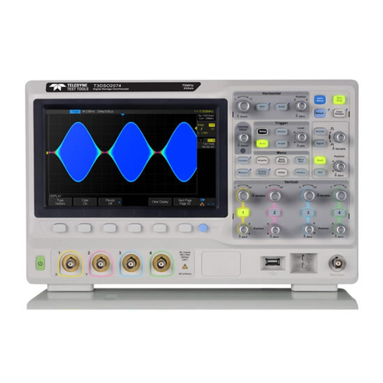
Appearance and Dimensions 352mm Figure 1: Front View Figure 2: Top View 1.800.561.8187 information@itm.com www. .com... -
Page 24: To Prepare The Oscilloscope For Use
To Prepare the Oscilloscope for Use To Adjust the Supporting Legs Adjust the supporting legs properly to use them as stands to tilt the oscilloscope upwards for stable placement of the oscilloscope as well as better operation and observation. Figure 3: Adjust the Supporting Legs 1.800.561.8187 information@itm.com www. -
Page 25: To Connect To Power Supply
To Connect to the Power Supply The oscilloscope will accept a 100~240V, 50/60Hz or 100~120V, 400Hz power supply. Please use the power cord provided with the accessories to connect the instrument to the power source as shown in the figure below. Power socket Figure 4: Connect to the Power Supply... -
Page 26: Power-On Inspection
Power-on Inspection When the oscilloscope is energized, press the power key at the lower-left corner of the front panel to start the oscilloscope. During the start-up process, the oscilloscope performs a series of self-tests and you can hear the sounds of relays switching. After the self-test is finished, the welcome screen is displayed. -
Page 27: To Connect The Probe
To Connect the Probe Teledyne Test Tools provides passive probes for the T3DSO2000 series oscilloscopes. For detailed technical information of the probes, please refer to the corresponding Probe User‘s Guide. Connect the Probe: 1. Connect the BNC terminal of the probe to one of the channel BNC connectors on the front panel. -
Page 28: Functional Inspection
Functional Inspection 1. Press the Default button on the front panel to restore the instrument to its factory default configuration. 2. Connect the ground alligator clip of the probe to the “Ground Terminal” under the probe compensation signal output terminal. Compensation Signal Output Terminal Ground Terminal 3. -
Page 29: Probe Compensation
Probe Compensation All oscilloscope probes should be properly compensated before their first use with the oscilloscope. Non-compensated or inadequate compensated probe may cause measurement inaccuracy or error. The probe compensation procedures are as follows. 1. Set the switch to 10X on the probe. 2. -
Page 30: The Front Panel
The Front Panel Figure 6: Front Panel Overview NO. Description NO. Description Horizontal Control Function Menus Auto Setup WaveGen Control Run/Stop Vertical Control for Analog Channels Default Setup WaveGen Output Probe Compensation/ Ground Clear Sweeps Terminal Universal Knob USB Host Trigger Control Digital Inputs Decode Control... -
Page 31: The Rear Panel
The Rear Panel Figure 7: Rear panel Overview 1. Handle Pull up the handle vertically for easy carrying of the instrument. When you do not need the handle, press it down. 2. LAN The instrument can be connected to a user-network via this interface to perform remote control. -
Page 32: Front Panel Function Overview
Front Panel Function Overview Horizontal Quickly enter the roll mode. The timebase range is from 1ns/div to 50s/div. Press the button to open the Zoom function and press again to close the function. Horizontal Position Knob: Sets the horizontal location of the trigger event on the display. -
Page 33: Vertical
Vertical Analog input channels. The four channels are marked by different colors which are also used to mark both the waveforms on the screen and the channel input connectors. Press channel button to open the corresponding channel and press again to turn it off. Vertical Position Knob: Set the vertical offset of the current waveform. - Page 34 Press the button to open the decode menu. Decode is an optional function. T3DSO2000 supports two serial buses shown as 1 and 2 for analog signal decoding. The protocols include I2C, SPI, UART/RS232, CAN and LIN. Press the button to open the digital channel function menu (Optional function). The T3DSO2000 support 16 digital channels and requires the optional leadset.
-
Page 35: Trigger
Trigger Press the button to open the trigger menu. The oscilloscope provides various trigger types: Edge, Slope, Pulse, Video, Window, Interval, Dropout, Runt, Pattern and Serial Bus (I2C/SPI/UART/RS232/CAN/LIN). Press the button to set to Auto trigger mode. Press the button to set to Normal trigger mode. Press the button to set to Single trigger mode. -
Page 36: Run Control
Run Control Press the button to enable the waveform auto setup function. The oscilloscope will automatically adjust the horizontal time base, vertical scale and trigger mode according to the input signal to provide a triggered stable display. Press the button to set the state of the instrument to “RUN” or “STOP”. In the “RUN”... -
Page 37: Universal Knob
Universal Knob 1. Adjust the waveform intensity When the menus are hidden, you can use the waveform intensity knob to adjust waveform intensity (0% ~ 100%). Turn clockwise to increase the brightness and counterclockwise to reduce. You can also press Display/Persist→Intensity and use the knob to adjust the intensity. -
Page 38: Menu
Menu Press the button to open the cursor function. It provides manual and tracking cursor modes. Press the button to enter the sampling menu. From here the acquisition mode can be set (Normal/Peak-Detect/Average/Eres), interpolation mode (Sinx/x or linear) and memory depth. The XY mode can be selected here as well as the Sequence function. -
Page 39: Help
Help The T3DSO2000 has an on line help function that supplies multi-language help information, that you can recall to help you operate the oscilloscope when you need. Press any button for 2 seconds to enter the online help. All sub-menus of every main menu have help information. -
Page 40: User Interface
User Interface Figure 9: User Interface 1. Settings Information Area Channel settings information items (numbers 3, 4, 5 and 7). 2. Channel Label/Waveform Different channels are marked by different colors and the color of the waveform matches with the color of the channel. 3. - Page 41 6. Trigger Position Label Display the trigger position of the waveform on the screen. 7. Frequency Counter Display the frequency of current waveform as trigger source. 8. Sampling Rate/ Memory Depth Display the current sample rate and memory depth of the oscilloscope. Use the Horizontal scale knob to modify the parameters.
-
Page 42: To Use The Security Lock
13. Menu Display menus of the currently selected function module. Press any menu softkey to select or adjust the corresponding setting. To Use the Security Lock Provisions for a Kensington-style lock are provided on the rear panel of the T3DSO2000 (Lock is not included). -
Page 43: To Set The Vertical System
To Adjust the Vertical System This chapter introduces how to adjust the vertical system of the oscilloscope. The contents of this chapter: � To Enable the Channel � To Adjust the Vertical Scale � To Adjust the Vertical Position � To Specify Channel Coupling �... -
Page 44: To Enable The Channel
To Enable the Channel T3DSO2000 provides 2/4 analog input channels (CH1, CH2, CH3, CH4) and provides independent vertical control system for each channel. As the vertical system setting methods of both channels are the same, this chapter takes CH1 as an example to introduce the configuration method of the vertical system. -
Page 45: To Adjust The Vertical Scale
To Adjust the Vertical Scale The vertical scale can be adjusted in Coarse or Fine mode. � Coarse adjustment (turning counterclockwise as an example): Set the vertical scale in 1-2-5 step namely 1mv/div, 2 mV/div, 5 mV/div, 10 mV/div …10 V/div. �... -
Page 46: To Specify Channel Coupling
To Specify Channel Coupling Set the coupling mode to filter out undesired signals. For this example, we will assume the signal-under-test is a square waveform with DC offset. � When the coupling mode set to DC: The DC and AC components of the signal-under-test can both pass into the T3DSO2000 channel. -
Page 47: To Specify Probe Attenuation Factor
To Specify Probe Attenuation Factor Set the probe attenuation factor to match the type of the probe that you are using to ensure correct vertical readouts. Press the CH1 button on the front panel; then press the Probe softkey and turn the Universal Knob to select the desired value and push the knob to confirm. -
Page 48: To Specify Amplitude Unit
To Specify Amplitude Unit Select the amplitude display unit for the current channel. The available units are V and A. When the unit is changed, the unit displayed in the channel label will change accordingly. 1. Press CH1 button on the front panel to enter the CH1 function menu. 2. -
Page 49: Set The Horizontal System
Adjusting the Horizontal System This chapter introduces how to adjust the horizontal system settings of the oscilloscope. The contents of this chapter: � Adjust the Horizontal Scale � Adjust the Trigger Delay � Set Roll Mode � Use the Zoom Function 1.800.561.8187 information@itm.com www. -
Page 50: Adjust The Horizontal Scale
Adjust the Horizontal Scale Turn the HORIZONTAL Scale Knob on the front panel to adjust the horizontal time base. Turn clockwise to reduce the horizontal time base and turn counterclockwise to increase. The time base information at the upper left corner of the screen will change accordingly during the adjustment. -
Page 51: Adjust Trigger Delay
Adjust Trigger Delay Turn the Position Knob on the front panel to adjust the trigger delay of the waveform. During the modification, waveforms of all the channels will move left or right and the trigger delay message at the upper-right corner of the screen changes accordingly. Press the knob to quickly reset the trigger delay. -
Page 52: Set The Roll Mode
Set the Roll mode Press the Roll button to enter the roll mode. In Roll mode the waveform moves slowly across the screen from right to left. It operates only on time base settings of 50 ms/div and slower. If the current time base setting is faster than the 50 ms/div limit, it will be set to 50 ms/div when Roll mode is entered. -
Page 53: Use The Zoom Function
Use the Zoom Function Zoom is a horizontally expanded version of the normal display. You can use Zoom to locate and horizontally expand part of the normal window for a more detailed horizontal analysis of the signals. Press the HORIZONTAL Scale Knob on the front panel to turn on the zoom function, and press the button again to turn off the function. -
Page 54: To Set The Sample System
To Set the Acquisition Sampling System This chapter introduces how to use the run control and set the sampling system of the oscilloscope. The contents of this chapter: � Run Control � Overview of Sampling � To Specify Memory Depth �... -
Page 55: Run Control
Run Control Press the Run/Stop or Single button on the front panel to run or stop the acquisition system of the scope. � When the Run/Stop is green, the oscilloscope is running, that is, acquiring data when trigger conditions are met. To stop acquiring data, press the Run/Stop button. When stopped, the last acquired waveform is displayed. -
Page 56: Overview Of Sampling
Overview of Sampling To understand the oscilloscope's sampling and acquisition modes, it is helpful to understand sampling theory, sample rate and oscilloscope bandwidth. Sampling Theory The Nyquist sampling theorem states that for a limited bandwidth (band-limited) signal with maximum frequency f , the equally spaced sampling frequency f must be greater than twice the maximum frequency f... -
Page 57: Sample Rate
Sample Rate The maximum sample rate of the T3DSO2000 is 2GSa/s. The actual sample rate of the oscilloscope is determined by the horizontal scale and acquisition depth. Turn the Horizontal Scale Knob to adjust the sample rate. The current sample rate is displayed in the information area at the upper-right corner of the screen. -
Page 58: Oscilloscope Bandwidth And Sample Rate
Oscilloscope Bandwidth and Sample Rate An oscilloscope‘s bandwidth is typically described as the lowest frequency at which input signal sine waves are attenuated by 3 dB (-30% amplitude error). At the oscilloscope bandwidth, sampling theory says the required sample rate is f = 2f However, the theory assumes there are no frequency components above f in this... -
Page 59: To Specify Memory Depth
To Specify Memory Depth Memory depth refers to the number of waveform points that the oscilloscope can store in a single trigger acquisition and it reflects the storage ability of the sample memory. The T3DSO2000 provides up to 140 Mpts memory depth. Press the Acquire button on the front panel;... -
Page 60: To Select Waveform Interpolation Method
To Select Waveform Interpolation Method Under real-time sampling, the oscilloscope acquires the discrete sample values of the waveform being displayed. In general, a waveform comprised of a singular dot per sample point is very difficult to observe. In order to increase the visibility of the signal, the digital oscilloscope usually uses the interpolation method to display a waveform. - Page 61 Figure 12: x Interpolation Interpolation Figure Sinx/x 1.800.561.8187 information@itm.com www. .com...
-
Page 62: To Select Acquisition Mode
To Select Acquisition Mode The acquisition mode is used to control how to generate waveform points from sampled points. The T3DSO2000 provides the following acquisition mode: Normal, Peak Detect, Average and Eres. 1. Press the Acquire button on the front panel to enter the ACQUIRE function menu; 2. -
Page 63: Peak Detect
Peak Detect In this mode, the oscilloscope acquires the maximum and minimum values of the signal within the sample interval to get the envelope of the signal or the narrow pulse of the signal that might be lost. In this mode, signal aliasing can be prevented but the noise displayed would be larger. -
Page 64: Average
Average In this mode, the oscilloscope averages the waveforms from multiple acquisitions to reduce the random (uncorrelated) noise of the input signal and improve the vertical resolution. The greater the number of averages, the lower the noise will be and the higher the vertical resolution will be, but the slower will be the response of the displayed waveform to waveform changes. -
Page 65: Eres (Enhanced Resolution)
Figure 18: With Random Noise, Average Mode Eres (Enhanced Resolution) This mode uses a digital filter to reduce the random noise on the input signal and generate much smoother waveforms on the screen. Eres can be used on both single-shot and repetitive signals and it does not slow down waveform update. -
Page 66: To Change The Horizontal Format
To Change the Horizontal Format Press the Acquire button on the front panel; then press the XY softkey to set the XY (On) or YT (Off) mode. The default setup is YT. It is the normal / default viewing mode for the oscilloscope. It’s a signal (Y axis) amplitude verses time (T, X axis) display. -
Page 67: Use Sequence Mode
Use Sequence Mode The Sequence Mode does not display the waveform during the sampling process. This improves the waveform capture rate by focusing the instrument resources on sampling. This increases the waveform capture rate to about 500,000 wfm/s. The Sequence Mode increases the ability to capture events with small probability effectively. - Page 68 display. 4. Press the softkey to replay the waveform from the current frame to 1. 5. Press the softkey to pause the replay. 6. Press the softkey to replay the waveform from the current frame to the last frame. 1.800.561.8187 information@itm.com www.
-
Page 69: To Trigger The Oscilloscope
Oscilloscope Triggering To observe and measure elements of an input waveform, it is most useful to have a stable and reproducible image of that waveform. To accomplish this, many oscilloscopes feature a trigger model that enables you to specify certain conditions for the input signal (only trigger on the rising edge, for example). - Page 70 The contents of this chapter: � Trigger Source � Trigger Mode � Trigger Level � Trigger Coupling � Trigger Holdoff � Noise Rejection � Trigger Type � Edge Trigger � Slope Trigger � Pulse Trigger � Video Trigger � Window Trigger �...
-
Page 71: Trigger Source
Trigger Source T3DSO2000 trigger sources include analog channels (CH1, CH2, CH3, CH4), as well as external trigger inputs EXT, EXT/5 and AC Line. Press the Setup button on the front panel to enter the TRIGGER function menu; press the Source softkey and then turn the Universal Knob to select the desired trigger source. The current trigger source is displayed at the upper right corner of the screen. -
Page 72: Trigger Mode
Trigger Mode T3DSO2000 trigger modes include Auto, Normal and Single. The trigger mode affects the way in which the oscilloscope searches for the trigger. After the oscilloscope begins to capture data, the oscilloscope operates by first filling the pre-trigger buffer. It starts searching for a trigger after the pre-trigger buffer is filled and continues to flow data through this buffer while it searches for the trigger. -
Page 73: Trigger Level
Trigger Level Trigger level and slope define the trigger point, Positive Slope Negative Slope Trigger Level Trigger Point Trigger Point Input Signal The trigger level can be adjusted for a selected analog channel by turning the Trigger Level Knob. Push the Trigger Level Knob to set the level to the middle of the waveform. If AC coupling is used, pushing the Trigger Level knob sets the trigger level to approximately 0 V. -
Page 74: Trigger Coupling
Trigger Coupling Press the Setup button on the front panel to enter the TRIGGER function menu, and then press the Coupling softkey and turn the Universal Knob or press the Coupling softkey continually to select the desired coupling mode. T3DSO2000 provides 4 trigger coupling modes: �... -
Page 75: Trigger Holdoff
Trigger Holdoff Trigger holdoff can be used to stabilize the triggering of complex waveforms (such as a pulse series). Holdoff time is the amount of time that the oscilloscope waits before re-arming the trigger circuitry. The oscilloscope will not trigger until the holdoff time expires. Use the holdoff to trigger on repetitive waveforms that have multiple edges (or other events) between waveform repetitions. -
Page 76: Noise Rejection
Noise Rejection Noise Reject adds additional hysteresis to the trigger circuitry. By increasing the trigger hysteresis band, you reduce the possibility of triggering on noise. However, this also decreases the trigger sensitivity so that a slightly larger signal is required to trigger the oscilloscope. - Page 77 If the signal you are probing is noisy, you can setup the oscilloscope to reduce the noise in the trigger path and on the displayed waveform. First, stabilize the displayed waveform by removing the noise from the trigger path. Second, reduce the noise on the displayed waveform.
-
Page 78: Trigger Type
Trigger Type T3DSO2000 provides multiple advanced trigger functions, including various serial bus triggers. � Edge trigger � Slope trigger � Pulse trigger � Video trigger � Window trigger � Interval trigger � DropOut trigger � Runt trigger � Pattern trigger 1.800.561.8187 information@itm.com www. -
Page 79: Edge Trigger
Edge Trigger Edge trigger distinguishes the trigger points by seeking the specified edge (rising, falling, rising & falling) and trigger level. Rising Edge Falling Edge Trigger Level Trigger Point Trigger Point 1. Press the Setup button on the front panel to enter the Trigger system function menu. 2. -
Page 80: Slope Trigger
Slope Trigger The slope trigger looks for a rising or falling transition from one level to another level in the specified time range. In T3DSO2000, positive slope time is defined as the time difference between the two crossing points of trigger level line A and B with the positive edge as shown in the figure below. - Page 81 5. Press the Limit Range softkey; then turn the Universal Knob to select the desired slope condition, and push down the knob to confirm. � < (less than a time value): Trigger when the positive or negative slope time of the input signal is lower than the specified time value.
-
Page 82: Pulse Trigger
Pulse Trigger Trigger on the positive or negative pulse with a specified width. Positive Pulse Width Trigger Level Negative Pulse Width 1. Press the Setup button on the front panel to enter the TRIGGER function menu. 2. Press the Type softkey; turn the Universal Knob to select Pulse and then push the knob to confirm. - Page 83 �� [--,--](within a range of time value): Trigger when the positive or negative pulse time of the input signal is greater than the specified lower limit of time and lower than the specified upper limit of time value. For example, for a positive pulse, if you set t (pulse real width) >100ns and t<300ns, the waveform will trigger.
-
Page 84: Video Trigger
Video Trigger Video triggering can be used to capture the complicated waveforms of most standard analog video signals. The trigger circuitry detects the vertical and horizontal interval of the waveform and produces triggers based on the video trigger settings you have selected. The T3DSO2000 supports standard video signals for NTSC (National Television Standards Committee), PAL (Phase Alternating Line) HDTV (High Definition Television) and custom video signal triggers. - Page 85 The table below takes Of Lines as 800 as an example to explain the relation between Of Lines, Of Fields, Interlace, Trigger Line and Trigger Field. Of Lines Of Fields Interlace Trigger Line Trigger Field 1,2,4 or 8 1, 1~2, 1~4, 1~8 1,2,4 or 8 1, 1~2, 1~4, 1~8 1,2,4 or 8...
- Page 86 Figure 27: Video Trigger To Use Custom Video Trigger Custom video trigger supports frame rates of 25Hz, 30Hz, 50Hz and 60Hz, and the line range is available from 300 to 2000. The steps below show how to set custom trigger. 1.
-
Page 87: Window Trigger
Window Trigger The windows trigger provides a high trigger level and a low trigger level. The instrument triggers when the input signal passes through the high trigger level or the low trigger level. There are two kinds of window types; Absolute and Relative. They have different trigger level adjustment methods. - Page 88 Figure 28: Absolute Window Trigger To set window trigger via Relative window type: 1. Press the Setup button on the front panel to enter the TRIGGER system function menu. 2. Press the Type softkey; then use the Universal Knob to select Window and push down the knob to confirm.
- Page 89 Figure 29: Relative Window Trigger 1.800.561.8187 information@itm.com www. .com...
-
Page 90: Interval Trigger
Interval Trigger Trigger when the time difference between the neighboring rising or falling edges meets the time limit condition (<, >, [--,--], --][--). Trigger Trigger To set interval trigger: 1. Press the Setup button on the front panel to enter the TRIGGER system function menu. - Page 91 Figure 30: Interval Trigger 1.800.561.8187 information@itm.com www. .com...
-
Page 92: Dropout Trigger
DropOut Trigger DropOut trigger includes two types: Edge and state. Edge Trigger when the time interval (△T), measured from when the rising edge (or falling edge) of the input signal passes through the trigger level to when the neighboring rising edge (or falling edge) passes through the trigger level, is greater than the timeout time set, as shown in the figure below. - Page 93 Figure 31: Edge DropOut Trigger To set state DropOut trigger: 1. Press the Setup button to enter the TRIGGER system function menu. 2. Press the Type softkey; then turn the Universal Knob to select DropOut and push the knob to confirm. 3.
-
Page 94: Runt Trigger
Runt Trigger The Runt trigger looks for pulses that cross one threshold but not another as shown in the picture below. Positive runt pulse High level Low level Negative runt pulse � A positive runt pulse across through a lower threshold but not an upper threshold. �... - Page 95 Figure 33: Runt Trigger 1.800.561.8187 information@itm.com www. .com...
-
Page 96: Pattern Trigger
Pattern Trigger The Pattern trigger identifies a trigger condition by looking for a specified pattern. The pattern trigger can be expanded to incorporate delays similar to other triggers. Pattern durations are evaluated using a timer. The timer starts on the last edge that makes the pattern ‘true’. - Page 97 � >(Greater Than) – When the pattern is present for greater than a time value. The trigger occurs � [--,--](In Range) – When the pattern is present for a time within a range of values. � --][-- (Out of Range) – When the pattern is present for a time outside of the range of values.
-
Page 98: Serial Trigger And Decode
Serial trigger and decode The oscilloscope provides IIC, SPI, UART/RS232, CAN and LIN serial trigger and decoding capabilities. This chapter introduces the method of triggering and decoding these serial signals in detail. The contents of this chapter: � IIC Trigger and Serial Decode �... -
Page 99: Iic Trigger And Serial Decode
IIC Trigger and Serial Decode The following section describes trigger and decoding for the IIC bus and is organized as follows: ‘Setup for IIC Signals’, ‘IIC Triggering’ and ‘IIC Decode’. Setup for IIC Signals Setting the IIC (Inter-IC bus) signal includes two steps: Connecting the serial data signal (SDA) and serial clock signal (SCK) to oscilloscope, specifying the threshold voltage of each input signal. - Page 100 trigger type is set to serial. (Tip: The SDA should be stable during the whole high clock cycle, otherwise it will be interpreted as a start or stop condition (data transitioning while the clock is high).) 7. Press softkey to return previous menu. 8.
-
Page 101: Iic Triggering
IIC Triggering This part introduces the nine kinds of trigger conditions (Start, Stop, Restart, No Ack, EEPROM, 7 Addr&Data, 10 Addr&Data and Data Length) and the methods of setting them. Introduction to the trigger conditions �� Start Condition— The oscilloscope will be triggered when the SDA signal transitions from high to low while the SCL clock is high. - Page 102 �� 7 Bit Address & Data: The oscilloscope will be triggered when the following conditions are satisfied. �� The address‘s length must be 7 bits and the address‘s value is the same as the trigger value. �� If you have set either Data1‘s or Data2‘s value, and the signal’s data is the same as that value.
- Page 103 �� 10 Bit Address & Data: The oscilloscope will be triggered when the following conditions are satisfied. �� The address‘s length must be 10 bits and the address‘s value is the same as the trigger value. �� If you have set either Data1‘s or Data2‘s value, and the signal has data of the same as value.
- Page 104 Figure 37: IIC TRIGGER Menu Press the Condition softkey and turn the Universal Knob to select the trigger condition: �� If you select the EEPROM condition: Press the Limit Range softkey to set the qualifier (=, < or >). Press Data1 softkey and set its value by turning the Universal Knob. ��...
-
Page 105: Iic Serial Decode
IIC Serial Decode After completing the setup of IIC signal and trigger, we will decode IIC signals. Operation steps as follows. 1. Press Decode→Decode. Select one of the options from the Decode1 and Decode2. Figure 38: IIC Decode Menu 2. Press Display and select On to display the result of decoding. 3. - Page 106 � The address of write frames are dark-green strings that contains ‘W’. � The address of read frames are yellow strings that contains ‘R’. � The data of frames are white strings. The lists of decoding result: � NO — The number of frames in screen. �...
-
Page 107: Spi Triggering And Serial Decode
SPI Triggering and Serial Decode The following section describes trigger and decoding for SPI and is organized as Follows: ‘Setup for SPI Signals’, ‘SPI Triggering’ and ‘SPI Decode’. Setup for SPI Signals Setting the SPI (Serial Peripheral Interface) signal includes two steps: Connecting the CLK, MISO, MOSI and CS signals to oscilloscope;... - Page 108 Set MISO: Press the MISO softkey to enter the MISO menu. Press the MISO softkey to select the channel that is connected to the SPI MISO signal. Press the Threshold softkey to set the SPI MISO signal threshold voltage level by Universal Knob.
- Page 109 High voltage level of CS signal is available If the time between two edges of clock signal is less than (or equal CLK Timeout to) the value of timeout, the signal between the two edges is treated as a frame. The range of clock timeout is 100ns-5ms. Press the Bit Order softkey to select the bit order (LSB or MSB).
-
Page 110: Spi Triggering
SPI Triggering This part will provide a brief introduction and description for the operation of the SPI trigger. 1. Press Setup key to enter the TRIGGER function menu. 2. Press Type and select Serial. 3. Press Protocol and select SPI. 4. - Page 111 8. Press the Next Page softkey. 9. Press the Bit Order softkey to set the bit order(MSB or LSB). Figure 45: SPI Trigger 1.800.561.8187 information@itm.com www. .com...
-
Page 112: Spi Serial Decode
SPI Serial Decode The following describes decoding of SPI signals. Operation steps as follows. 1. Press Decode→Decode. Select one of the options from the Decode1 and Decode2. 2. Press Display and select On to display the result of decoding. 3. Press List to enter the LIST function menu. 4. - Page 113 The lists of decoding result: � NO — the number of frames in screen. � TIME (timestamp) — the horizontal displacement between current frame and trigger position. � MISO - the decoding result of ‘Master-In, Slave-Out’ line. � MOSI - the decoding result of ‘Master-Out, Slave-In’ line. 1.800.561.8187 information@itm.com www.
-
Page 114: Uart/Rs232 Trigger And Serial Decode
UART/RS232 Trigger and Serial Decode The following section describes trigger and decoding for UART/RS232 bus types and is organized as follows: ‘Setup for UART/RS232 Signals”, “UART/RS232 Triggering’ And ‘UART/RS232 Decode’. Setup for UART/RS232 Signals Press the Decode key to enter the DECODE function menu. Press the Decode softkey and select the desired decoder (Decode1 or Decode2). - Page 115 Figure 48: BUS CONFIG Menu 10. Press Baud softkey to set the baud rate. � The baud rate can be set as predefined value. � If the desired baud rate is not listed, press Baud and select custom option, press the Custom and turn the Universal Knob to set the desired baud rate. 11.
-
Page 116: Uart/Rs232 Triggering
UART/RS232 Triggering This part will provide a brief introduction and description for the operation of the UART trigger. 1. Press Setup key to enter the TRIGGER function menu. 2. Press Type and select Serial. 3. Press Protocol and select UART. 4. - Page 117 Figure 50: UART Trigger 1.800.561.8187 information@itm.com www. .com...
-
Page 118: Uart/Rs232 Serial Decode
UART/RS232 Serial Decode After completing the setup of UART signal and trigger, we will decode UART signals. Operation steps as follows. 1. Press Decode→Decode. Select one of the options from the Decode1 and Decode2. 2. Press Display and select On to display the result of decoding. 3. - Page 119 Interpreting UART/RS232 Decode The frames of decoding result: � RX— The decoding result of the data received. � TX— The decoding result of the data transmitted. The lists of decoding result: � NO — The number of frames in screen. �...
-
Page 120: Can Trigger And Serial Decode
CAN Trigger and Serial Decode The following section describes trigger and decoding for the CAN bus and is organized as follows: ‘Setup for CAN Signals’, ‘CAN Triggering’ and ‘CAN Serial Decode’. Setup for CAN Signals Press the Decode key to enter the DECODE function menu. Press the Decode softkey and select the desired slot (Decode1 or Decode2). - Page 121 �� If the desired baud rate is not listed, press Baud and select custom option, press the Custom and turn the Universal Knob to set the desired baud rate. Press Decode Source to select the signal to be decoded. � CAN_H —...
-
Page 122: Can Triggering
CAN Triggering This part will provide a brief introduction and description for the operation of the CAN trigger. To introduce the trigger conditions � Start— The oscilloscope will be triggered at the start bit of a frame. � Remote — The oscilloscope will be triggered by a remote frame with specified ID. �... - Page 123 significant bits can be changed.) �� If you select the ID+DATA condition: a. Press ID bits softkey to select the ID‘s length (11or 29 bits). b. Press Curr ID Byte softkey and use the Universal Knob to select the byte that you want to modify.
-
Page 124: Can Serial Decode
CAN Serial Decode After completing the setup of can signal and trigger, we will decode CAN signals. Operation steps as follows. 1. Press Decode→Decode. Select one of the options from the Decode1 and Decode2. 2. Press Display and select On to display the result of decoding. 3. - Page 125 Interpreting CAN Decode. The frame of decoding result: � Arbitration field is displayed in frame � Control field is displayed in frame � Data field is displayed in frame � CRC field is displayed in frame The list of decoding result: �...
-
Page 126: Lin Triggering And Serial Decode
LIN Triggering and Serial Decode The following section describes trigger and decoding for the LIN bus and is organized as follows: ‘Setup for LIN Signals’, ‘LIN Triggering’ and ‘LIN Decode’. Setup for LIN Signals There are two steps of setting the LIN signal: Connecting the signal to oscilloscope and specifying the parameters of each input signal. -
Page 127: Lin Triggering
LIN Triggering This part will provide a brief introduction and description for the operation of the LIN trigger. To introduce the trigger conditions �� Break— The oscilloscope will be triggered at the position of the break field‘s break delimiter. �� ID (Frame ID) — The oscilloscope will be triggered at the position of identifier field‘s stop bit, if the value of a frames ID is equal to the specified value. - Page 128 5. Press Condition and select the trigger condition by the Universal Knob: �� If you select ID condition: Press ID softkey and set its value by turning the Universal Knob. �� If you select ID+DATA condition: Press ID softkey and set its value by turning the Universal Knob. Press DATA1 softkey and set its value by turning the Universal Knob.
-
Page 129: Lin Serial Decode
LIN Serial Decode After completing the setup of SPI signal and trigger, we will decode SPI signals. Operation steps as follows. 1. Press Decode→Decode. Select one of the options from the Decode1 and Decode2. 2. Press Display and select On to display the result of decoding. 3. - Page 130 � Data Length is displayed in the frame � Data Field is displayed in the frame. � Checksum Field is displayed in the frame. The list of decoding result: � NO — The number of frames in screen. � TIME (timestamp) — The horizontal displacement between the current frame and trigger position.
-
Page 131: Digital Channels
Digital Channels This chapter describes how to use the digital channels of a Mixed-Single Oscilloscope (MSO). The digital channels are enabled on T3DSO2000 series oscilloscopes that have the MSO activation license installed. This chapter contains the following items: � To Connect the Digital Probes to the Device-under-test �... -
Page 132: To Connect The Digital Probes To The Device-Under-Test
To Connect the Digital Probes to the Device-under- test 1. If necessary, turn off the power supply to the device-under-test. �� Turning off the power to the device-under-test prevents damage that might occur if you accidentally short lines together while connecting probes. You can leave the oscilloscope powered on because no voltage appears at the probes. -
Page 133: Acquiring Waveform Using The Digital Channels
Acquiring Waveform Using the Digital Channels Press the Digital button on the front panel to open the digital channels and start acquiring digital channel waveforms. For digital channels, each time the oscilloscope takes a sample it compares the input voltage to the logic threshold. If the voltage is above the threshold, the oscilloscope stores a 1 in the sample memory;... - Page 134 Figure 60: Middle Display Type Figure 61: High Display Type The display type control lets you spread out or compress the digital traces vertically on the display for more convenient viewing. 1.800.561.8187 information@itm.com www. .com...
-
Page 135: To Switch A Single Channel On Or Off
To Switch a Single Channel On or Off 1. Press the Digital button on the front panel to open the DIGITAL function menu. 2. Press the Channel Control softkey, then turn the Universal Knob to select the desired channel such as Dx and push down the knob to confirm. 3. -
Page 136: To Reposition A Digital Channel
� The threshold you set applies to all channels. � Values greater than the set threshold are high (1) and values less than the set threshold are low (0). � If the D0~D7 or D8~D15 softkey is set to Custom, press the Custom softkey, then turn the Universal Knob to select the desired value and push the knob to confirm. - Page 137 line at the bottom of the display. Light blue shows the digital channel is included in the bus while black shows it is excluded in the bus. � Under the DIGITAL function menu, press the System Display softkey to select Binary or Hex to display the bus values.
-
Page 138: To Save Reference Waveform
To Save Reference Waveform T3DSO2000 can save analog channels or math waveforms to one of four reference waveform locations in the oscilloscope internal memory. Then, a reference waveform can be displayed and compared against other waveforms. Four reference waveforms can be displayed at a time. -
Page 139: To Save Ref Waveform To Internal Memory
To Save REF Waveform to Internal Memory Do the following steps to save the REF waveform to internal memory: 1. Press the REF button on the front to enter the REF WAVE function menu. Note that when the time horizontal format is in X-Y mode, REF function cannot be enabled. 2. -
Page 140: To Adjust Ref Waveform Display
To Adjust REF Waveform Display 1. Please refer to the ‘To Display REF Waveform’ above to display the desired reference waveform. 2. Use the Vertical Scale knob and Vertical Position knob for Math/Ref to adjust the vertical scale and position of the reference waveform. The vertical scale and position information displays in the middle of the screen. -
Page 141: To Use The Math Operation
To Use the Math Operation T3DSO2000 supports many math operations between analog channels and reference waveforms, including addition (+), subtraction (-), multiplication (*), division (/), differential (d/dt), integral (∫dt), square root (√). The resulting math waveform is displayed in white and labelled with ‘M’. -
Page 142: Units For Math Waveforms
Units for Math Waveforms Use the channel function menu to set the unit of each channel to ‘V’ or ‘A’. T3DSO2000 math operation includes the units shown below: Math Operation Unit Addition (+)or subtraction (-) V, A ∧ ∧ multiplication (*) 2, A 2 or W (Volt-Amp) division (/) -
Page 143: Math Operators
Math Operators T3DSO2000 supports standard math operations (addition, subtraction, multiplication, division), FFT (Fast Fourier Transform) operation, and complex math functions (differential, integral, square root). Addition or Subtraction Math operators perform arithmetic operations, addition or subtraction, on any two analog input channels. When you select addition or subtraction, the Source A and Source B values are added or subtracted point by point, and the result is displayed. -
Page 144: Multiplication And Division
Multiplication and Division Math operators perform arithmetic operations, multiplication or division operation, on any two analog input channels. When you select multiplication or division, the Source A and Source B values are multiplied or divided point by point and the result is displayed. 1. -
Page 145: Fft Operation
FFT Operation FFT is used to compute the fast Fourier transform using analog input channels or reference waveforms. FFT takes the digitized time record of the specified source and transforms it to the frequency domain. When the FFT function is selected, the FFT spectrum is plotted on the oscilloscope display as magnitude in dBV versus frequency. - Page 146 To display a FFT waveform: 1. Press the Math button on the front panel to open the MATH function menu. 2. Press the Operation softkey and then turn the Universal Knob to select FFT. The resulting math waveform is displayed in white and labeled with ‘M’. 3.
- Page 147 � Split: the source channel and the FFT operation results are displayed separately. The time domain and frequency domain signals are displayed clearly. � Full Screen: the source channel and the FFT operation results are displayed in the same window to view the frequency spectrum more clearly and to perform more precise measurements.
- Page 148 To measure the FFT waveform: To make cursor measurements, press the Cursors button, and then press the Mode softkey to select On to turn the cursors on. Use the X1 and X2 cursors to measure the frequency values and the difference between two frequency values (ΔX). Use the Y1 and Y2 cursors to measure amplitude in dB and difference in amplitude (ΔY).
-
Page 149: Differentiate
Differentiate d/dt (differentiate) calculates the discrete time derivative of the selected source. Where: � d = differential waveform. � y = channel 1, 2, 3, or 4 data points. � i = data point index � Δ t =point-to-point time difference. The dx option under d/dt math function operation menu shows the point-to-point time difference, and it ranges from 0.02div to 0.40div. -
Page 150: Integrate
Integrate dt (integrate) calculates the integral of the selected source. You can use integrate to calculate the energy of a pulse in volt-seconds or measure the area under a waveform. dt plots the integral of the source using the "Trapezoidal Rule". The equation is: �... -
Page 151: Square Root
Figure 71: Integral with Offset Square Root Square root (√) calculates the square root of the selected source. Where the transform is undefined for a particular input, holes (zero values) appear in the function output. Figure 72: Square Root 1.800.561.8187 information@itm.com www. -
Page 152: To Adjust The Math Waveform Scale And Offset
To Adjust the Math Waveform Scale and Offset To Adjust the Math Waveform Horizontal Scale and Offset you can do some horizontal and vertical adjustment to check and analyze parts of a math waveform or to find an event-of-interest. To adjust the math waveform horizontal scale and offset 1. -
Page 153: To Make Cursor Measurements
To Make Cursor Measurements Cursors are horizontal and vertical markers that indicate X-axis values and Y-axis values on a selected waveform source. You can use cursors to make custom voltage and time measurements on input waveforms. X Cursors X cursors are vertical dashed lines that adjust horizontally and can be used to measure time (when the source is FFT waveform, X cursors measure frequency) X1 cursor is the leftmost (default position) vertical dotted line;... -
Page 154: To Make Cursor Measurements
To Make Cursor Measurements 1. Press the Cursors button on the front panel to enter the CURSOR function menu. 2. Press the Mode softkey and set the option to On. 3. Press the Source softkey, and then use the Universal Knob to select the desired source. -
Page 155: To Make Measurements
To Make Measurements T3DSO2000 provides measurements of 36 waveform parameters as well as basic statistics on those measured values. It contains voltage, time and delay parameters. Voltage and time parameters are under the Type option. The results of the last five selected measurements are displayed at the bottom of screen and above the menu. -
Page 156: Type Of Measurement
Type of Measurement Voltage Measurements Voltage measurements include 15 kinds of voltage parameter measurements. Figure 74: Voltage Measurements 1. Pk-Pk: The peak-to-peak value is the difference between Maximum and Minimum values. 2. Vmax: Maximum is the highest value in the waveform display. 3. - Page 157 Figure 75: Overshoot 14. Preshoot: Preshoot is distortion that precedes a major edge transition expressed as a percentage of Amplitude. The X cursors show which edge is being measured (edge closest to the trigger reference point). Figure 76: Preshoot 15. L@T: The voltage value of the trigger point 16.
-
Page 158: Time Measurements
Time Measurements Time measurements include 9 kinds of time parameter measurements. Figure 77: Time Measurements 1. Period: Defined as the time between the middle threshold points of two consecutive, like-polarity edges. 2. Frequency: Defined as the reciprocal of period. 3. + Width: The time difference between the 50% threshold of a rising edge to the 50% threshold of the next falling edge of the pulse. -
Page 159: Delay Measurements
Delay Measurements Delay measurements measure the time-based values between any two channels. 1. Phase: The phase difference between two channels. 2. FRR: The time between the first rising edge of source 1 and the first rising edge of source 2 of 50 voltage level. 3. -
Page 160: To Make Automatic Measurements
To Make Automatic Measurements Perform the steps below and select voltage or time parameters to make automatic measurements. 1. Press the Measure button on the front panel to enter the MEASURE function menu. 2. Press the Source softkey, and then use the Universal Knob to select the desired channel. - Page 161 Figure 79: Add the Measurement Note: If the parameter does not match the measured condition, it will display as ‘****’. 1.800.561.8187 information@itm.com www. .com...
-
Page 162: To Clear Measurement Parameters
To Clear Measurement Parameters Press the Clear softkey to clear all the measurement parameters that are displayed on the screen. To Make ‘All Parameter Measurements’ All measurements can measure all the voltage, time and delay parameters of the current measurement source. The table of results will be displayed on the screen. Figure 80: All Parameters Measurement Do the following steps to activate the All Parameters display: Press the Measure button on the front panel to enter the MEASURE function menu. -
Page 163: Display Setting
Display Setting The display type, color, persistence, grid type, waveform intensity, grid brightness and transparence are all adjustable. The contents of this chapter: � To Set Display Type � To Set Color Display � To Set and Clear Persistence � To Clear the Display �... -
Page 164: To Set Display Type
To Set Display Type Press the Display button on the front panel, and then press the Type softkey to select Vectors or Dots display type. � Vectors: the sample points are connected by lines and displayed. Normally, this mode can provide the most vivid waveform to view the steep edge of the waveform (such as square waveform). -
Page 165: To Set Color Display
To Set Color Display Color temperature mode uses the change of the waveforms‘ color to reflect the change of the waveforms‘ appearing probability. This mode uses a change in color instead of the more common change in intensity. The greater the probability that the waveform appears, the warmer the color is;... -
Page 166: To Clear The Display
Figure 84: Persist Set to Infinite 3. When the Persist is On, to erase the results of previous acquisitions from the display, press the Clear Persist softkey. The oscilloscope will start to accumulate acquisitions again. 4. To return to the normal display mode, turn off persist and the previous acquisitions will be cleared at once. -
Page 167: To Select Grid Type
To Select Grid Type To select grid type 1. Press the Display/Persist button on the front panel to enter the DISPLAY function menu. 2. Press the Next Page softkey to go to the second page of the Display function menu. 3. - Page 168 Figure 85: Intensity Set to 100% Figure 86: Intensity Set to 10% Note: Waveform intensity adjustment affects analog channel waveforms only (not math waveforms, reference waveforms, digital waveforms, etc.). 1.800.561.8187 information@itm.com www. .com...
-
Page 169: To Adjust Grid Brightness
To Adjust Grid Brightness Do the following steps to adjust the grid brightness: 1. Press the Display button on the front panel to enter the DISPLAY function menu. 2. Press the Next Page softkey to go to the second page of the Display function menu. 3. -
Page 170: Save And Recall
Save and Recall Oscilloscope setups, waveforms, pictures, and CSV files can be saved to internal oscilloscope memory or to a USB storage device. The saved setups, waveforms can be recalled later. T3DSO2000 provides an USB Host interface on the front panel to connect an USB device for external storage. -
Page 171: Save Type
Save Type T3DSO2000 supports setups, waveforms, pictures and CSV files storage. The default save type is setups. 1. Setups It‘s the default storage type of T3DSO2000. T3DSO2000 saves the settings of the oscilloscope in internal or external memory in ‘*.SET’ format. At most 20 setting files (from No.1~No.20) can be stored in internal memory. -
Page 172: Internal Save And Recall
Internal Save and Recall Internal save and recall support Setups in Save/Recall. In the following part, the save and recall method and procedures are introduced. �� Save the specified oscilloscope setting in internal memory. 1. Connect the signal to the oscilloscope and obtain stable display. 2. -
Page 173: External Save And Recall
External save and recall Before using external storage and recall, make sure that the USB flash device is connected correctly. External storage supports all available file types. The oscilloscope cannot recall/save Picture or CSV file types. �� Save the specified type of file to the external USB flash device. 1. - Page 174 Figure 88: Select Save Location 6. After the save position is selected, press the New softkey to turn on the interface as shown in the figure below. Refer to the descriptions in “To Create a new file or fold” to create a new file name. Figure 89: File Name Dialogue 7.
- Page 175 �� Load the specified type of file in the external USB storage device. 1. Press the Save/Recall button on the front panel to enter the SAVE/RECALL function menu. 2. Press the Recall softkey to enter the RECALL function menu. 3. Press the Type softkey to select Reference or Setups 4.
-
Page 176: Disk Management
Disk Management Disk management is used in save and recall operations after the oscilloscope is connected to a USB storage device. Before using an external disk, make sure that the USB storage device is connected correctly. Execute the following operations through the disk management menu: �... -
Page 177: To Create A New File Or Folder
To Create a New File or Folder This operation is only valid in external storage. The T3DSO2000 supports English alphabet characters, letters, numbers, underscores and spaces. Let‘s use an example to introduce how to create a file or folder. Example: create a file or folder named ‘DSO2013ab’ 1. -
Page 178: To Delete A File Or Folder
11. Press the Enter softkey to enter the file name. You will see a file or folder named ‘DSO2013ab’. To delete a file or folder This operation is only valid in external storage. 1. Press the Save/Recall button on the front to enter the SAVE/RECALL function menu. 2. -
Page 179: System Function Setting
System Function Setting This function module supports the oscilloscope‘s system-related functions, such as system status, language, sound and other advanced settings. It allows access to self-calibration, firmware update and remote interface configuration. The contents of this chapter: � To View the System Status �... -
Page 180: To View The System Status
To View the System Status Do the following steps to view the system status: 1. Press the Utility button on the front to enter the UTILITY function menu. 2. Press the System Status softkey to view the system status of the oscilloscope. The system status includes the information below: �... -
Page 181: To Do Self-Calibration
To Do Self-Calibration The self-calibration program quickly enables the oscilloscope to utilize the best working state and to provide the most precise measurement values. You can perform self-calibration at any time, especially when there has been a change in the external ambient temperature of 5 ℃or more. -
Page 182: To Enable Or Disable The Sound
To Enable or Disable the Sound When the sound is enabled, the sound of the beeper will be heard when a function key or a menu softkey is pressed or when the prompt message pops up. Press the Utility button on the front panel to enter the UTILITY function menu; then press Sound softkey to select to turn on or off the sound. -
Page 183: To Enable Pass/Fail Test
To Enable Pass/Fail Test One way to verify a waveform's compliance to a particular set of parameters is to use pass/fail testing. A pass/fail defines a region of the oscilloscope's display in which the waveform must remain in order to comply with chosen parameters. Compliance to the mask is verified point-by-point across the display. -
Page 184: To Set And Perform Pass/Fail Test
To Set and Perform Pass/Fail Test Do the following steps to set and perform pass/fail test: 1. Press the Utility button on the front panel to enter the UTILITY function menu. 2. Press the Next Page softkey to go to the second page of the UTILITY function menu. 3. -
Page 185: To Save And Recall Test Mask
To Save and Recall Test Mask Users can save the current test mask to the internal Flash memory or external USB flash device. The file format of the test mask file is ‘*.RGU’. �� Save Test Mask to Internal Memory 1. - Page 186 �� Save Test Mask to External Memory Do the following steps to save the test mask to external memory: 1. Press the Utility button on the front panel to enter the UTILITY function menu. 2. Press the Next Page softkey to go to the second page of the UTILITY function menu. 3.
-
Page 187: I/O Set
I/O Set T3DSO2000 provides abundant I/O interfaces, including: USB Device, LAN and Aux Output. To Set the USB Device Do the following steps to set the oscilloscope to communicate with PC via USB: 1. Install the USBTMC device driver on a PC. The latest compatible version of National Instruments VISA is suggested. -
Page 188: To Set The Lan
To Set the LAN Do the following steps to set the oscilloscope to communicate with a PC via LAN: 1. Connect the oscilloscope to your local area network using the network cable. 2. Press the Utility button on the front panel to enter the UTILITY function menu. 3. -
Page 189: To Set Aux Output
To Set Aux Output Users can set the type of the signal output from the [Trigger Out] connector at the rear panel. 1. Press the Utility button on the front panel to enter the UTILITY function menu. 2. Press the I/O Set softkey to enter the I/O SET function menu. 3. -
Page 190: To Enable Quick-Cal
To Enable Quick-Cal Quick-Cal can automatically calibrate the T3DSO2000 when ambient temperature variations are affecting the measurement accuracy. If the temperature environment that the T3DSO2000 is working in is not stable, perform the following steps: 1. Press the Utility button on the front panel to enter the UTILITY function menu. 2. -
Page 191: To Update Firmware And Configuration
To Update Firmware and Configuration The firmware and configuration can be updated directly via the USB flash drive. Do the following steps to update the firmware: 1. Insert the USB flash drive containing the firmware and the configure files into the USB host interface on the front panel of the oscilloscope. -
Page 192: To Perform A Self-Test
To Perform a Self-Test Self-tests include screen test, keyboard test, control knobs and LED test. Screen Test 1. Press the Utility button on the front panel to enter the UTILITY function menu. 2. Press the Next Page softkey to go to the second page of the UTILITY function menu. 3. -
Page 193: Keyboard Test
Keyboard Test Keyboard test is used to test that the keys or the knobs are working correctly. Do the following steps to do keyboard test: 1. Press the Utility button on the front panel to enter the UTILITY function menu. 2. -
Page 194: Led Test
LED Test LED test is used to test that if the button lights work well. 1. Press the Utility button on the front panel to enter the UTILITY function menu. 2. Press the Next Page softkey to go to the second page of the UTILITY function menu. 3. -
Page 195: To Specify The Screen Saver Time
To Specify the Screen Saver Time When the oscilloscope enters the idle state and holds for a certain period of time, the screen saver program will be enabled. Do the following steps to set the screen saver time: 1. Press the Utility button on the front panel to enter the UTILITY function menu. 2. -
Page 196: Option Management
Option Management The T3DSO2000 provides multiple options to fulfil your measurement requirements. Please contact your sales representative or technical support to order the corresponding options. You can view the options currently installed on the oscilloscope or activate the newly purchased option license codes through this menu. Do the following steps to install the option on the oscilloscope: 1. - Page 197 Figure 101: Option Information 1.800.561.8187 information@itm.com www. .com...
-
Page 198: To Use The History Function
To Use the History Function The history function can record the waveforms of the input channels before pressing the Run/Stop button. In the run state, the oscilloscope records input waveform continually; when the memory becomes full (reaches the maximal frame), the new acquisitions will replace the old acquisitions keeping the latest versions. - Page 199 enough time to wait for the entire acquisition. 4. Press the softkey to replay the waveform from the current frame to 1. 5. Press the softkey to stop replay. 6. Press the softkey to replay the waveform from the current frame to the last frame.
-
Page 200: Arbitrary Waveform Generator
Arbitrary Waveform Generator The T3DSO2000 supports a built-in arbitrary waveform generator. that can be used to source sine, square, ramp, pulse, DC, noise, cardiac, Gauss pulse, exp rise, exp fall and arbitrary waveforms. The contents of this chapter: � To Set Wave Type and Parameters �... -
Page 201: To Set Wave Type And Parameters
Setting the Waveform Type and Parameters 1. Press the WaveGen button on the front panel to open the built-in arbitrary waveform generator function. The first press lights up the backlight of the button, opens the output and enters the WAVEFORM function menu. A second press of the WaveGen button will turn off the backlight and the output. - Page 202 Offset / Offset Fine / Low-Level / Pulse 1uHz~10MHz 4mV~6V ± 3.0V Low-Level-Fine / Width / Width Continued Fine value. Use the Universal Knob to ± 3.0V adjust the Offset value. Use the Universal Knob to Noise adjust the Stdev/ Mean value. Use the Universal Knob to adjust the Frequency / Frequency Fine / Period / Period / Fine /...
-
Page 203: To Output Arbitrary Waveform
To Output Arbitrary Waveform 1. Press the Wave Gen button on the front panel to enable the AWG function and enter the WAVEFORM function menu. 2. Connect the T3DSO2000 to a PC which is running the EasyWave software using a USB cable. 3. -
Page 204: To Set Output Load
To Set Output Load 11. Press the Wave Gen button on the front panel to enter the WAVEFORM function menu. 12. Press the Setting softkey to enter the SETTING function menu. 13. Press the Output Load softkey to select High-Z or 50Ω. Figure 105: SETTING Function Menu The output load of the Wave Gen must match with the oscilloscope, or the amplitude of the signal will be incorrect. -
Page 205: To Do Awg Self-Cal
AWG Self-Cal If the ambient operating temperature changes more than 5°and the instrument runs more than more 30 minutes, run the AWG self cal routine to reduce the environmental thermal change effects 1. Press the Wave Gen button on the front panel to enter the WAVEFORM function menu. -
Page 206: Default Setup
Default Setup Press the Default button on the front panel to set the T3DSO2000 back to the factory default values as shown below: Horizontal T/div 1μs/div Delay Zoom Format Vertical Channel on/off V/div 1 V/div Offset Coupling BW Limit Full Adjust Coarse Probe... - Page 207 Persist Grid Intensity Brightness Transparence Cursor Mode Type Source -3.5 μs 3.5 μs Save/Recall Type Setups Save To Internal Setup NO.1 Utility IO Set USB Device USBTMC Aux Output Trig Out Sound Sound Pass/Fail Enable Test Source Operate Mes Display X Mask Y Mask Location...
- Page 208 Math Operate Source A Source B Invert V/div 1.00 V/div offset Source A Source B Invert V/div 1.00 V/div offset Source A Source B Invert V/div 1.00 V^2/div offset 0 V^2 Source A Source B Invert V/div 1.0/div offset Source Window Hanning Horizontal...
- Page 209 Vertical Scale 1.00 eve/div Vertical Offset √ Source CH1 Vertical Scale 1.00 V /div Vertical Offset Source Location REF A Display Decode Serial 1 Serial Display List Serial 2 Serial Display List Threshold 1.60 V Threshold 1.60 V Address 7bits Threshold 1.60 V Edge Select...
- Page 210 UART/RS232 Threshold 1.60 V Threshold 1.60 V Bound 9600 Parity Check None Stop Bit Idle Level Data Length CAN-H Threshold 1.60 V CAN-L Threshold 1.60 V Bound 100kb/S Decode Source CAN_H Source Threshold 1.60 V Baud 2400 Wave Gen Function O f f Wave Type Sine...
- Page 211 Pulse Frequency 1KHz Amplitude 4Vpp Offset 0Vdc Width 200μs Offset 0.0 mVdc Noise Stdev 448 mV Mean 0 mV Cardiac Frequency 1 KHz Amplitude 4 Vpp Offset 0 Vdc Gauss Pulse Frequency 1 KHz Amplitude 4 Vpp Offset 0 Vdc Exp Rise Frequency 1 KHz...
-
Page 212: Troubleshooting
Teledyne LeCroy support. Restart the instrument after completing the steps listed above. If these steps do not solve the problem, please contact Teledyne LeCroy. After the signal is sampled, there is no corresponding waveform displayed Check to make certain the probe is not faulty. - Page 213 USB of hard disk type. Make sure the system format of used USB disk is FAT32. Restart the instrument and then insert the USB to verify operation. If a problem persists, please contact Teledyne LeCroy support. 1.800.561.8187 information@itm.com www.
- Page 214 .com © 2018 Teledyne Test Tools is a brand and trademark of Teledyne LeCroy Inc. All rights reserved. Specifications,prices,availability and delivery subject to change without notice. Product brand or brand names are trademarks or requested trademarks of their respective holders.
Need help?
Do you have a question about the T3DSO2000 Series and is the answer not in the manual?
Questions and answers