Table of Contents
Advertisement
Quick Links
Download this manual
See also:
Operator's Manual
Advertisement
Table of Contents

Related Manuals for Teledyne LabMaster 10 Zi Series


Summary of Contents for Teledyne LabMaster 10 Zi Series
- Page 1 Getting Started Manual LabMaster 10 Zi Series Oscilloscopes...
- Page 3 LabMaster 10 Zi Series Oscilloscopes Getting Started Manual May, 2013...
- Page 4 However, clients are encouraged to distribute and duplicate Teledyne LeCroy documentation for their own internal educational purposes. Teledyne LeCroy and other product or brand names are trademarks or requested trademarks of their respective holders. Information in this publication supersedes all earlier versions. Specifications are subject to change without notice.
-
Page 5: Table Of Contents
Getting Started Manual Contents Welcome ......................1 Safety Instructions................... 2 Symbols ......................2 Precautions ...................... 2 Operating Environment ................... 3 Cooling ......................3 Cleaning ......................4 Lifting and Moving ................... 4 Calibration ......................4 Power ....................... 5 LabMaster 10 Zi Overview ................7 Front of MCM-Zi Master Control Module ............ - Page 6 LabMaster 10 Zi Oscilloscopes Basic Controls ....................37 Front Panel Control Groups ................37 Display Dashboard ..................42 Turning On Traces ..................55 Timebase ....................... 56 Timebase Dialog ..................... 56 Combining Channels ..................56 Sampling Modes ..................... 58 Vertical ......................67 Channel Dialog ....................
- Page 7 Getting Started Manual Measurements .................... 107 Turning On Measurements ................107 Quick Access to Parameter Setup Dialogs ........... 107 Parameter Setup ..................108 Measure Modes ................... 109 Help Markers....................110 Math ......................112 Math Setup ....................112 Analysis ....................... 114 Track vs.
- Page 8 Reference ....................166 Warranty ...................... 166 Specifications ....................167 Certifications ....................167 Contact Teledyne LeCroy ................171 ® End-User License Agreement for Teledyne LeCroy X-Stream Software ..172 ® Windows License Agreement ..............191 Index ......................192 922561-00 Rev A...
-
Page 9: Welcome
When your product is delivered, verify that all items on the packing list or invoice copy have been shipped to you. Contact your nearest Teledyne LeCroy customer service center at the address listed in this manual or your national distributor if anything is missing or damaged. If you do not contact us immediately, we cannot be responsible for replacement. -
Page 10: Safety Instructions
LabMaster 10 Zi Oscilloscopes Safety Instructions Observe generally accepted safety procedures in addition to the precautions specified here to keep the instrument operating in a correct and safe condition. The overall safety of any system incorporating this instrument is the responsibility of the assembler of the system. Symbols These symbols appear on the instrument's front or rear panels and in documentation to alert you to important safety considerations. -
Page 11: Operating Environment
Getting Started Manual Observe all terminal ratings. Do not apply a voltage to any input (C1, C2, C3, C4 or EXT) that exceeds the maximum rating of that input. Refer to the front of the oscilloscope for maximum input ratings. Use only within operational environment listed. -
Page 12: Cleaning
Schedule an annual factory calibration as part of your regular maintenance. Extended warranty, calibration, and upgrade plans are available for purchase. Contact your Teledyne LeCroy sales representative or customersupport@teledynelecroy.com to purchase a service plan. 922561-00 Rev A... -
Page 13: Power
Getting Started Manual Power AC Power Source 100 to 240 VAC (±10%) at 50/60 Hz (± 10%) Manual voltage selection is not required because the instrument automatically adapts to line voltage. Power Consumption MCM-Z ASTER ONTROL ODULE Max. consumption (all accessories installed): ≤ 450 watts (450 VA) Standby consumption: 5W CQUISITION ODULES... - Page 14 LabMaster 10 Zi Oscilloscopes WARNING. Interrupting the protective conductor inside or outside the oscilloscope, or disconnecting the safety ground terminal, creates a hazardous situation. Intentional interruption is prohibited. CAUTION Do not place the instrument so that it is difficult to reach the power cord inlet to disconnect the instrument.
-
Page 15: Labmaster 10 Zi Overview
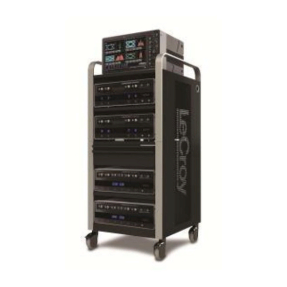
Getting Started Manual LabMaster 10 Zi Overview LabMaster 10 Zi is a unique modular oscilloscope solution that allows a configuration of more channels at higher bandwidths than conventional four channel oscilloscopes. It is ideally suited for test situations where there are many lanes of serial data to be captured and analyzed simultaneously, where crosstalk analysis is performed, or for capturing four or more channels at the highest-possible bandwidths for optical coherent... - Page 16 : If your LabMaster system runs multiple Acquisition Modules, for optimal channel access and convenience, Teledyne LeCroy recommends stacking the modules on top of each other on your bench, inside Teledyne LeCroy's available OC910 or inside a rack (modules must be specifically ordered for rack mounting from the Teledyne LeCroy factory).
-
Page 17: Front Of Mcm-Zi Master Control Module
Getting Started Manual Front of MCM-Zi Master Control Module The MCM-Zi Master Control Module includes Controls, Display, CPU, and ChannelSync Clock Architecture. All acquisition capability is contained in separate Acquisition Modules. Number and Description Power Button 3. Host USB Ports Front Panel Control Release Switch Fast Edge Output... -
Page 18: Back Of Mcm-Zi Master Control Module
LabMaster 10 Zi Oscilloscopes Back of MCM-Zi Master Control Module Number and Description 1. ChannelSync Outputs - 3. 10 MHz Reference 6. The I/O Panel SMA 10 GHz Clock and Clock Input (Grounded 7. DVI-D Video Output PCIe 1 Lane Control EMI Shield required 8. -
Page 19: Front Of 10-Xxzi Acquisition Module
Buttons NOTE: If your system runs multiple Acquisition Modules, for optimal channel access and convenience, Teledyne LeCroy recommends stacking the modules on top of each other on your bench, inside Teledyne LeCroy's available OC910 oscilloscope cart, or inside of your own rack (modules must be specifically ordered for rack mounting from the Teledyne LeCroy factory). -
Page 20: Back Of 10-Xxzi Acquisition Module
LabMaster 10 Zi Oscilloscopes Back of 10-xxZi Acquisition Module Number and Description 1. ChannelSync 3. PCIe 4 Lane 4. AC Power Inlet SMA 10 GHz Data Output Clock Input 2. ChannelSync PCIe 1 Lane Control Input NOTE : Only MCM-Zi Master Control Module has 10 MHz Reference Clock Input/Output connections. -
Page 21: Front Of Channelsync Mainframe Hub
Getting Started Manual Front of ChannelSync Mainframe Hub Back of ChannelSync Mainframe Hub Number and Description ChannelSync 4. PCIe 4 Lane Data Input ChannelSync PCIe 1 SMA 10 GHz (from MCM-Zi) Lane Control Input Clock Output (from MCM-Zi) 5. 10 MHz REF In ChannelSync 6. -
Page 22: Input/Output Panel
LabMaster 10 Zi Oscilloscopes Input/Output Panel The available connections on I/O panels are the same for all LabMaster 10 Zi configurations. I/O panels are located on the back of the Master Control Module. See Back of MCM-Zi Master Control Module (on page 10) for more information. -
Page 23: Standard High Bandwidth Accessories
Getting Started Manual Standard High Bandwidth Accessories The following accessories are delivered in a soft accessory case (SAC-01A) with 50-65 GHz acquisition modules. 10dB Attenuators Used instead of an internally switched attenuator Qty. 2 (V-V) for optimal signal fidelity. Needed when >640mVp- p signals (>80 mV/div) are input to the acquisition module. -
Page 24: Labmaster Setup
LabMaster 10 Zi Oscilloscopes LabMaster Setup PCIe 1 Lane Cable SYNC Connection(s) Connect each PCIe 1 Lane Control Input on the back of your 10-xxZi Acquisition Modules to a PCIe 1 Lane Output on the MCM-Zi Master Control Module using the PCIe 1 Lane cable(s) provided. PCIe 1 Lane Cable On the back of the Master Control Module, plug one end of the PCIe 1 Lane cable into the PCIe 1 Lane Channel Sync Output (labeled SYNC). - Page 25 Getting Started Manual Now, connect the other end of the 1 Lane cable into the SYNC socket on the back of the Acquisition Module. Repeat these steps for every additional Acquisition Module in your system. PLEASE NOTE THE FOLLOWING: PCIe 1 Lane Cable plugs are keyed with a single groove along one wide side of the plug.
-
Page 26: Pcie 4 Lane Datalink Connection(S)
LabMaster 10 Zi Oscilloscopes PCIe 4 Lane DATALINK Connection(s) Continue making PCI Express connections by cabling the PCIe 4 Lane Data Output on the back of each 10-xxZi Acquisition Module to the PCIe 4 Lane Data Inputs on the back of the MCM-Zi Master Control Module using the cable(s) provided. - Page 27 Getting Started Manual On the back of the Acquisition Module, connect a PCIe 4 lane cable to the PCIe 4 Lane Data Output (labeled DATALINK). Now, on the back of the Master Control Module, connect the other end of the same PCIe 4 Lane cable into the corresponding PCIe 4 Lane Data Input (labeled DATALINK CHANNEL).
- Page 28 LabMaster 10 Zi Oscilloscopes Repeat these steps for each Acquisition Module in your system. PLEASE NOTE THE FOLLOWING: PCIe 4 Lane Cable plugs are keyed with a single groove along one wide side of the plug. The plug must be inserted into the socket with the groove aligned properly.
-
Page 29: Sma 72" Cables - Channelsync Clock
Getting Started Manual SMA 72" Cables - ChannelSync Clock Usethe SMA 72" cable(s) provided to connect each SMA 10 GHz Clock Output on the back of your MCM-Zi Master Control Module to the SMA 10 GHz Clock Input on each 10-xxZi Acquisition Module in your system. NOTE : Use an SMA torque wrench to ensure connections are properly tightened. - Page 30 LabMaster 10 Zi Oscilloscopes Now, on the back of the Acquisition Module, connect the other end of the same SMA 72" cable into the corresponding SMA 10 GHz Clock Input (labeled REF). Repeat the previous steps for every additional Acquisition Module in your system.
-
Page 31: Channelsync Mainframe Hub
Getting Started Manual ChannelSync Mainframe Hub The CMH-20 ChannelSync Mainframe Hub provides a simple and effective means to expand a LabMaster system beyond 20 channels (5 Acquisition Modules). This is accomplished without any degradation of the timing accuracy specifications. The Mainframe Hub is populated with cards for each acquisition module (the back panel of the CMH-20 shown below is populated with 20 cards for use with 20 Acquisition Modules, or 80 total channels). -
Page 32: Power Cable And Main Power Switch
LabMaster 10 Zi Oscilloscopes Power Cable and Main Power Switch Teledyne LeCroy advises that you note the power ratings of the individual modules and connect them to suitably rated circuits. MCM-Zi Control Module comes with an IEC60320 Type C13 power inlet connector. -
Page 33: Touch Screen And External Displays
Getting Started Manual Touch Screen and External Displays You may operate the instrument using the built-in touch-screen or attach an external monitor for extended desktop operation. A properly configured external touch-screen monitor will take on all the touch-screen capabilities of the internal display. NOTE: If the external monitor uses a Fujitsu touch screen driver, it will not work as a touch screen but will support extended desktop operation. - Page 34 LabMaster 10 Zi Oscilloscopes Both displays before Dual Display Mode selection. In this example, the top monitor is the external display. 922561-00 Rev A...
- Page 35 Getting Started Manual Grids distributed after Dual Display Mode selection. Trace descriptor boxes move with the trace (note the movement of C1-C4). Other controls remain on the primary display (Display 1, which in this example is the bottom, internal display). 922561-00 Rev A...
-
Page 36: Removing And Attaching The Front Panel
LabMaster 10 Zi Oscilloscopes Removing and Attaching the Front Panel Detach the Front Panel Control from the oscilloscope by sliding the detachment lever to the left and pulling at the right. 922561-00 Rev A... - Page 37 USB - A to USB - Mini B cable provided. NOTE : While a standard front panel comes with your Zi oscilloscope, Teledyne LeCroy offers additional standard front panels or a 4 channel version to better suit the way you work. 922561-00 Rev A...
-
Page 38: Signal Inputs
LabMaster 10 Zi Oscilloscopes Signal Inputs Probes Teledyne LeCroy offers a variety probes for use with your oscilloscope. The types compatible with the LabMaster 10 Zi are listed below. Visit teledynelecroy.com for specifications and ordering information. Single-Ended - A single-ended, active probe is associated with measuring voltages at high frequencies. -
Page 39: Probus Interface
Getting Started Manual Most active probes match probe to oscilloscope response automatically using probe response data stored in an on-board EEPROM. This ensures the best possible combined probe plus oscilloscope channel frequency response without the need to perform any de-embedding procedure. Interfaces differ in bandwidth capabilities, so the interfaces contained on your oscilloscope—and their exact location—depend on the bandwidth rating of the oscilloscope model you purchased. - Page 40 LabMaster 10 Zi Oscilloscopes The 2.92 mm high-bandwidth electrical paths are comprised of two connector halves/subassemblies which have a common mating interface: The first connector half is mounted onto the oscilloscope connector panel. The outer end of this connector has a combination of grooves, external threads and a coaxial interface with a 2.92 mm airline geometry.
- Page 41 Getting Started Manual To attach the female-female barrel adapter: 1. Remove the white cap from the V-male connector on the high bandwidth input of the 10-xxZi acquisition module. Turn it counterclockwise to loosen it. 2. Insert the female-female barrel adapter into the V-male connector. 922561-00 Rev A...
- Page 42 LabMaster 10 Zi Oscilloscopes 3. Gently turn the V-male connector in the counterclockwise direction until it is finger tight. 4. Insert the hand wrench over the flat portion of the barrel adapter. This will hold the barrel adapter still while the V-male connector is tightened around it.
-
Page 43: Probe Dialog
Dialog displays probe attenuation and other information, and allows you to make tip select and other probe settings from the oscilloscope touchscreen. The following figure shows a typical channel dialog on a Teledyne LeCroy oscilloscope containing both 2.92 mm (Input A) and 1.85 mm (Input B) interfaces. - Page 44 LabMaster 10 Zi Oscilloscopes When the probe is not connected, there is only a C1 tab selection for vertical channel setup and the user has the ability to select input coupling and probe attenuation. Channel dialog showing Input A's interface controls setup before connection. After a probe is connected, it is recognized and an additional tab with the probe model name is displayed to the right of the C1 tab.
-
Page 45: Basic Controls
Getting Started Manual Basic Controls Front Panel Control Groups Many Front Panel controls directly correspond with Screen Layout Controls. For example, the Print front panel button is associated with one of the Hardcopy function at Utilities → Utilities Setup → Hardcopy. 922561-00 Rev A... - Page 46 LabMaster 10 Zi Oscilloscopes Miscellaneous Controls / WaveStream Indicator Help - Opens the Teledyne LeCroy Online Assistant. If the second monitor is installed, the online help opens on the second monitor. Default Setup - Resets the oscilloscope's settings to the default configuration.
-
Page 47: Trigger Front Panel Controls
Getting Started Manual Trigger Front Panel Controls Level – Sets the trigger level to 50%. Turn the knob to change the trigger threshold level. The threshold level is indicated on the Trigger label. READY and TRIG'D Indicators - The READY indicator is lit when the trigger is armed. -
Page 48: Horizontal Front Panel Controls
LabMaster 10 Zi Oscilloscopes Horizontal Front Panel Controls Note : Horizontal front panel controls correspond with screen menu selection: Timebase → Horizontal Setup.. Delay - Toggles between a zero horizontal delay value and the previous horizontal delay value. Turn to change the horizontal delay value. -
Page 49: Zoom And Math Front Panel Controls
Getting Started Manual Channels – Control channel ON/OFF and which channel is active for the Vertical Offset and Volts/Div knobs controls. If a channel is OFF, pressing that channel button turns it on and makes it active. If a channel button is ON, pressing that channel button makes it active, and then pressing it a second time turns it OFF. -
Page 50: Display Dashboard
LabMaster 10 Zi Oscilloscopes Quick Zoom - Automatically displays magnified views of up to four signal inputs on multiple grids. With four input signals, the signals are displayed along with four zoom traces, each on its own grid. Pressing this button also turns off all other traces. -
Page 51: Menu Bar
Getting Started Manual Menu Bar The top of the screen contains a menu bar of commonly used functions. Whenever you touch one of these buttons and make a selection from its drop-down menu, the dialog area at the bottom of the screen displays the corresponding dialog. - Page 52 LabMaster 10 Zi Oscilloscopes Stop - Press to prevent the oscilloscope from triggering on a signal. If you boot up the instrument with the trigger in Stop mode, the message "no trace available" is shown. Trigger Setup - Press to open the Trigger Setup... dialog. Corresponds with screen menu selection: Trigger →...
-
Page 53: The Signal Display Grid
Getting Started Manual The Signal Display Grid The grid area is divided into 8 vertical divisions and 10 horizontal divisions just like any other oscilloscope. Set up the signal display area by touching Display → Display Setup... from the menu bar. The Display dialog offers a choice of grid combinations and can also set the grid intensity. -
Page 54: Trace Descriptor Labels
LabMaster 10 Zi Oscilloscopes where the new level ends up when triggering resumes. Push the LEVEL knob to reset the level to 50%. Zero Volts Level - This indicator is located at the left edge of the grid. Change the zero volts level by turning the vertical OFFSET knob. - Page 55 Getting Started Manual (DSQ), coupling (DC/GND), bandwidth limiting (BWL), and averaging (AVG). These indicators have a long and short form, respectively. The long and short forms of trace descriptor indicators. Besides channel traces, math and parameter measurement labels are also displayed.
- Page 56 LabMaster 10 Zi Oscilloscopes HORTCUT UTTONS You can access the same functions as available from the Signal Display Grid Pop-Up menu by touching a trace-descriptor label to open the setup dialog. From the setup dialog, shortcut buttons enable you to: ...
- Page 57 Getting Started Manual From this pop-up you can edit existing annotations, change the label placement on the waveform, add labels, remove labels, and toggle the visibility. If you are modifying an existing label, under Labels touch the label you want to change. NOTE : If the Channel dialog for the trace you want to annotate is currently displayed, touch the Label button at the bottom to display the Trace...
-
Page 58: Dialog Area
LabMaster 10 Zi Oscilloscopes Dialog Area The lower portion of your oscilloscope screen is where information is shown, selections are made, and data is input. These screens are organized into tabular displays, subtabs, or pop-up dialogs. The dialog area is controlled by Touch Screen Controls and Front Panel Controls. - Page 59 Getting Started Manual NTRY ONTROLS For most entry fields, touch once then enter a value using an attached keyboard (or double-touch/click to use the Virtual keyboard). OLDER ROWSING ONTROLS These controls allow for navigation to or from folders (on the hard drive or memory device) for retrieving or storing items such as waveforms, LabNotebook entries, to name a few.
- Page 60 LabMaster 10 Zi Oscilloscopes NOTE : The instrument's hard disk is partitioned into drives. Drive C: contains the Windows operating system and the instrument application software. Drive D: is intended for data files. LYOUT ONTROLS Flyout Menus provide additional options for a particular font panel control. A set of touch screen buttons appear at the right-side of the display.
- Page 61 Getting Started Manual Pop-Up Keypad Some models provide a pop-up Keypad when you touch twice in the same control. For many controls, the Front Panel Controls (on page 16) can be used to adjust the value in the pop-up. The Pop-Up contains Up and Down arrow buttons, Set to Max, Default, and Min buttons, and the Keypad itself for providing your value.
- Page 62 LabMaster 10 Zi Oscilloscopes Measure - Opens the Measure menu. You can then select a parameter from this menu without leaving the Channel Setup dialog. The parameter automatically appears below the grid. Zoom - Creates a zoom trace of the channel trace whose dialog is currently displayed.
-
Page 63: Turning On Traces
Getting Started Manual Message Bar At the bottom of the oscilloscope display is a narrow message bar. The current date and time are displayed at the far right. Status, error, or other messages are also shown in this area. Turning On Traces To turn on a trace, do one of the following: ... -
Page 64: Timebase
LabMaster 10 Zi Oscilloscopes Timebase Timebase Dialog You can access Timebase settings by: Using the front panel Horizontal controls, Choosing Timebase → Horizontal Setup... from the menu bar Touching the Timebase trace descriptor label. The main Timebase dialog contains sections for choosing Sampling Mode, Timebase Mode, and Real Time Memory. - Page 65 Getting Started Manual Choose TimeBase → Horizontal Setup... to access the Timebase dialog. If you have more than one Acquisition module, touch the DBI tab to show the DBI dialog. Otherwise, use the Digital Bandwidth Interleave area to the far right of the Timebase dialog. Select the inputs to combine by touching the corresponding higher bandwidth button beneath the pair (in the image below, 36 GHz C1 and C2 are combined into one 65 GHz C2).
-
Page 66: Sampling Modes
LabMaster 10 Zi Oscilloscopes Sampling Modes Depending on your timebase, you can choose: Real Time Sampling Mode (below) - Also known as single-shot sampling mode, a series of digitized voltage values sampled on the input signal at a uniform rate. Sequence Sampling Mode (on page 59) - Many trigger events stored as segments into the oscilloscope's memory. - Page 67 Getting Started Manual the other hand, allows you to sample the waveform starting at the equivalent of 10,000 divisions after the event occurred. On fast timebase settings, the maximum single-shot sampling rate is used. But for slower timebases, the sampling rate is decreased and the number of data samples maintained.
- Page 68 LabMaster 10 Zi Oscilloscopes You can use Sequence mode in remote operation to take full advantage of the instrument's high data-transfer capability. In Sequence mode, the complete waveform consists of a number of fixed- size segments acquired in single-shot mode (see the instrument specifications for the limits).
- Page 69 Getting Started Manual EQUENCE ISPLAY ODES The instrument gives you a choice of five ways to display your segments: Adjacent Waterfall (cascaded) Mosaic (tiled) Overlay Perspective NOTE : some display modes have limitations on the number of segments that can be shown at one time.
- Page 70 LabMaster 10 Zi Oscilloscopes EQUENCE ETUP When setting up Sequence Mode, you define the number of fixed-size segments acquired in single-shot mode (see the instrument specifications for the limits). The oscilloscope uses the sequence timebase setting to determine the capture duration of each segment. Along with this setting, the oscilloscope uses the number of segments, maximum segment length, and total available memory to determine the actual number of samples or segments, and time or points.
- Page 71 Getting Started Manual Touch the Enable Timeout checkbox. Touch the Timeout data entry control and provide a timeout value. NOTE : Use the sequence mode timeout to automatically interrupt the sequence acquisition if the timeout value is exceeded without a valid trigger. Num Segments The timeout period accounts for instances when a miscount occurs for some reason and the oscilloscope waits indefinitely for...
- Page 72 LabMaster 10 Zi Oscilloscopes OOMING EGMENTS IN EQUENCE You can zoom individual segments easily using the Zoom front panel button. When you zoom, the zoom traces default to Segment 1. Channel descriptors indicate the total number of segments acquired. Zoom descriptors indicate [Seg #] and #Segments in the Zoom.
- Page 73 Getting Started Manual If you want to increase or decrease your horizontal or vertical zoom in small increments, touch the Var. checkbox to enable variable zooming. Now with each touch of the zoom control buttons, the degree of magnification changes by small increments.
- Page 74 LabMaster 10 Zi Oscilloscopes IEWING TAMPS You can view time stamps for each segment. View Segment Time Stamps Touch Timebase → Acquisition Status on the menu bar. Touch Vertical → Channel Status on the menu bar. Touch the Trigger Time tab. Under Show Status For, touch the Time button.
-
Page 75: Vertical
Getting Started Manual Vertical You can access Vertical settings using the front panel Vertical controls, by selecting Vertical→ Channel Setup... on the menu bar, or by touching the Channel trace descriptor label. The following screen-shot shows the C1 dialog on a LabMaster. For each open channel trace, a corresponding Cx dialog opens with setup controls. - Page 76 The exact settings vary by model. Probe - Teledyne LeCroy's 1.85 mm and 2.92 mm probe inputs automatically senses probes and sets their attenuation for you. For each channel, the probe attenuation can also be set manually.
- Page 77 Getting Started Manual the continuous average gradually tends to zero (following an exponential rule) at a rate that decreases as the weight increases. Deskew - Adjusts the horizontal time offset by the amount entered. The valid range is dependent on the current timebase setting. Pre- processing deskew and the Math deskew function perform the same activity.
-
Page 78: Response Optimization Modes
When zero group delay is provided at all frequencies, preshoot and overshoot is equalized. Teledyne LeCroy provides three choices for response optimization. Each combines a frequency and group delay response to optimize the oscilloscope for particular applications. -
Page 79: Labmaster Channel Setup
Getting Started Manual LabMaster Channel Setup You can adjust the sensitivity and the positioning of the waveforms and set the color of the trace for up to 80 channels on the Channel Setup dialog. The example shown below illustrates Channel Setup with a 20 channel LabMaster. -
Page 80: Labmaster Deskew Calibration
LabMaster 10 Zi Oscilloscopes LabMaster Deskew Calibration The ChannelSync™ architecture in LabMaster modular oscilloscope systems utilizes a single 10 GHz distributed clock for all acquisition modules. This provides precise timing alignment and timing accuracy between all channels in all acquisition modules as found in a single, conventional oscilloscope package. - Page 81 Getting Started Manual There are two different deskew calibrations that can be performed. Both permit quick and easy deskew of all of the channels in all LabMaster acquisition modules by automatically deskewing all channels to a user- designated reference channel, with the common deskewed reference plane being the input channel connectors on the acquisition module.
- Page 82 LabMaster 10 Zi Oscilloscopes Touch the SystemSkew Cal button. The System Channel/Trigger Skew Calibration Wizard opens. Connect the Fast Edge output on the front of the Master Control Module to Channel 1, then on the Wizard touch Next. The Fast Edge output will be displayed on Channel 1 during the operation.
- Page 83 Getting Started Manual When the previous operation is complete, you will be prompted to use the same cable as used to connect to Channel 1 to connect the Fast Edge output to Channel 5. After connecting, touch Next again. Continue following on-screen prompts for as many additional modules there are.
- Page 84 LabMaster 10 Zi Oscilloscopes If you perform ChannelSync Cal on multiple gain settings, perform it first on the 100 mV/div setting, then perform it on other gain settings (with “Reference Correction” values entered as appropriate for those other gain settings.) ...
- Page 85 Getting Started Manual From the menu bar, choose Vertical > Channel <#> Setup. Touch the ChannelSync Cal tab to the right of the C<#> tab. Place a checkmark next to the module(s) you want to calibrate and touch the ChannelSync Cal button. The ChannelSync Calibration Wizard opens.
- Page 86 LabMaster 10 Zi Oscilloscopes As with System Skew calibration, you will see the Fast Edge output signal appear on the display and delay (skew) measurements will be made. Connect the Fast Edge calibration signal to the next input (in this example, C2), then touch the Next button.
-
Page 87: Trigger
Getting Started Manual Trigger Trigger Overview NOTE : Trigger capabilities on channel 1-4 (i.e., the first acquisition module) are more complete than on channels 5 or higher. Full Edge trigger bandwidth is available on all channels, but SMART triggers are not available on Channel 5 or higher. -
Page 88: Trigger Types
LabMaster 10 Zi Oscilloscopes Trigger Types A set of standard trigger types is available for selection. These triggers are basic waveform features or conditions such as a positive or negative slope and are available on all oscilloscopes, along with tools like Software Assisted Trigger and Trigger Scan. - Page 89 Getting Started Manual Smart This trigger group sets conditions on signals with rare features. INDOW A trigger occurs when a signal enters or exits a window defined by adjustable thresholds. NTERVAL While Glitch trigger performs over the width of a pulse, Interval trigger performs over the width of an interval: the signal duration (the period) separating two consecutive edges of the same polarity, positive to positive or negative to negative.
- Page 90 LabMaster 10 Zi Oscilloscopes Measurement This trigger type allows you to leverage parameter measurements as waveform trigger conditions. A measurement trigger is either the only trigger or the final trigger in a chain of trigger events including hardware triggers. MultiStage This is a set of trigger types where the trigger event depends on a series of earlier conditions being met.
-
Page 91: Trigger Settings
Channel 4 would still be the input channel for the serial trigger signal. Complete information on the operation of this trigger can be obtained in the Teledyne LeCroy Serial Data Debug Solutions manual posted on the Teledyne LeCroy website. Trigger Settings... -
Page 92: Trigger Setup
LabMaster 10 Zi Oscilloscopes The time value is given in the title line of the Timebase label at the lower-right of the grid. Vertical Turn the L knob in the TRIGGER control group to adjust the trigger's EVEL vertical threshold. Turn this knob to adjust the level of the trigger source or the highlighted trace. - Page 93 Getting Started Manual Touch inside the trigger Source control for your first Setup configuration and select a source on which to trigger. Touch inside the Coupling control and select a coupling mode. Coupling refers to the type of signal coupling at the input of the trigger circuit.
-
Page 94: Optimize For Hf
LabMaster 10 Zi Oscilloscopes The Amplitude and Range of the trigger level have limits as detailed in the datasheet specifications regularly maintained at www.teledynelecroy.com. Touch inside the Level data entry control and provide a value using your preferred input control method. Additional information on using the touch screen controls can be found in the Dialog Area. -
Page 95: Holdoff By Time Or Events
Getting Started Manual In Range and Out of Range conditions can be further specified by setting: Limits and assigning Upper and Lower Values to the range. Delta and assigning Nominal width and Delta. NOTE : Width Condition settings are summarized on the far right of the dialog. Holdoff by Time or Events Holdoff is an additional condition of Edge and Pattern triggers. - Page 96 LabMaster 10 Zi Oscilloscopes Edge Trigger with Holdoff by Time. The broken upward-pointing arrows indicate potential triggers, which would occur if other conditions are met. The bold arrows indicate where the triggers actually occur when the holdoff time has been exceeded. FF BY VENTS Select a positive or negative slope and a number of events.
-
Page 97: Auxiliary Input Trigger
Getting Started Manual Auxiliary Input Trigger Some instrument models provide auxiliary input trigger capability. It's done as a pattern trigger, on the Ext dialog. Select X1, or ÷10. You can also select from DC50Ω, Gnd, and DC1MΩ Impedance values. 922561-00 Rev A... -
Page 98: Triggerscan
LabMaster 10 Zi Oscilloscopes TriggerScan TriggerScan is a debugging tool (available for any trigger type) that helps you quickly find rare waveform glitches and anomalies. With TriggerScan, you can build a list of trigger setups to look for rare events and automatically sequence through each one. -
Page 99: Training Triggerscan
Getting Started Manual Training TriggerScan The TriggerScan Trainer inspects a currently acquired waveform and automatically builds a list of common trigger setups used to find rare events. NOTE : Run the Trainer if you want to change the trigger types or if you change the channel or signal. -
Page 100: Starting Triggerscan
LabMaster 10 Zi Oscilloscopes Starting TriggerScan After you have run the Trainer, the Trigger List displays a list of smart trigger setups. You can add or remove trigger setups. You can also update the selected smart trigger setup. Once you have made any changes to the Trigger List, you are ready to start scanning. -
Page 101: Saving Triggerscan Setups
Getting Started Manual PLEASE NOTE THE FOLLOWING: You can tune the dwell time that the oscilloscope waits before loading the next trigger setup using the Dwell Time data entry control. If you have Persistence display mode enabled, all trigger events are recorded on the display. -
Page 102: Viewing Waveforms
In order to accomplish this while still providing the ability to view many signals at one time on the oscilloscope display Teledyne LeCroy provides multi-grid capability. This creates multiple oscilloscope grids, each with 8-bit vertical resolution, and allows many full-resolution grids (but vertically smaller in grid height) for concurrent display without affecting the vertical resolution. -
Page 103: Display Setup
Getting Started Manual Display Setup To adjust the appearance of the oscilloscope display: From the menu bar, touch Display → Display Setup..Touch Grid and select one of the display type buttons. The image on each button indicates its corresponding grid configuration. Auto Grid automatically adds or deletes grids as you select more or fewer waveforms to display. -
Page 104: Moving Traces From Grid To Grid
LabMaster 10 Zi Oscilloscopes Moving Traces from Grid to Grid You can move traces from grid to grid with the touch of a button. Double-touch the trace descriptor label to activate the waveform you want to move and open the setup dialog. Touch the Next Grid shortcut button at the bottom of the setup dialog. -
Page 105: Persistence
Getting Started Manual Dual Display Grid Selection Make a dual grid display selection for showing on an external display (once properly connected to the I/O panel) by selecting Display → Display Setup..Numbered labels on this image correspond with the following steps. - Page 106 LabMaster 10 Zi Oscilloscopes Setup All Input Channels at Once 1. Touch the All Locked button. 2. Touch one of the Mode buttons. 3. Touch the Show last trace checkbox if you want the last trace displayed. 4. Touch inside the Saturation data entry control and provide a whole number integer.
-
Page 107: Wavestream Display Mode
Getting Started Manual WaveStream Display Mode This fast viewing mode provides brightness-graded intensity with a decay time similar to the action of phosphor on an analog screen. WaveStream mode operates at up to 80 GS/s with an update rate of up to several thousand waveforms/second for better capture of higher frequency abnormal events. -
Page 108: Zooming Waveforms
LabMaster 10 Zi Oscilloscopes Zooming Waveforms You can magnify a selected region of a waveform using the Zoom function. On Zi model oscilloscopes, you can display up to four Zoom (Z1 - Z4) and eight Math Zoom traces (F1 - F8). You can zoom: ... -
Page 109: Zooming A Single Channel
Getting Started Manual Zooming a Single Channel The Zoom button appears as a standard button at the bottom of the channel Cx Vertical Adjust setup dialog for you to create a zoom trace of your input waveform. On the menu bar, touch Vertical → Channel X Setup..Touch the channel trace descriptor label for a displayed channel. -
Page 110: Touch-And-Drag Zooming
LabMaster 10 Zi Oscilloscopes Horizontal Position - Press to reset the horizontal zoom position to zero. Turn to change the horizontal position of the selected math or zoom trace. Horizontal Ratio - Press to toggle between fixed and variable horizontal zoom ratio adjustment. -
Page 111: Quick Zoom
Getting Started Manual Quick Zoom Quickly create a Zoom trace by either pressing the front panel Zoom button or touching the Zoom button on the respective channel dialog. Turning Off Zoom Turn off a Zoom by either pressing the front panel Zoom button again. On the corresponding Zoom dialog, touch the Trace On checkbox to remove the check mark and disable the zoom trace. -
Page 112: Cursors
LabMaster 10 Zi Oscilloscopes Cursors Cursors are important tools that aid you in measuring signal values. Cursors are markers - lines, cross-hairs, or arrows - that you can move around the grid or the waveform itself. Use cursors to make fast, accurate measurements and eliminate guesswork. -
Page 113: Cursor Setup
Getting Started Manual Cursor Setup After using one of the above methods to access cursors, the Cursors dialog is displayed. Cursor Types Horizontal Abs - Provides a single, dashed, vertical line and cross-hair marking for the specific cursor location. None of the Show controls are provided;... -
Page 114: Cursors On Math Functions
LabMaster 10 Zi Oscilloscopes mark the Track checkbox which allows you to move your Position 1 cursor (using the touch-screen display or front panel control) and have both cursors then move together and maintaining their relative distance from their originally specified positions. The Show controls display cursor value results on the signal's corresponding Trace Descriptor label as follows: ... -
Page 115: Measurements
Getting Started Manual Measurements Parameters are measurement tools that determine a wide range of waveform properties. Use them to automatically calculate many attributes of your waveform, like rise-time, rms voltage, and peak-to-peak voltage. There are parameter modes for the amplitude and time domains, custom parameter groups, and parameters for pass and fail testing. -
Page 116: Parameter Setup
Math On Parameters performs math (addition, subtraction, multiplication, division) on parameters indicated on the Source1 and Source2 controls. Advanced Web Edit uses Teledyne LeCroy's Processing Web for measurement setup. This feature, available with the XWEB option, allows you to chain practically unlimited math functions together for operation on your waveform measurements. -
Page 117: Measure Modes
Getting Started Manual If you selected Math On Parameters, touch inside the Math Operator data entry field and select a math function from the pop-up menu. In the mini-dialog to the right of the main setup dialog, touch the Gate tab to narrow the span of measurement. Touch the Accept tab to define parameter values to be used in the measurement. -
Page 118: Help Markers
LabMaster 10 Zi Oscilloscopes To select a Measure Mode: Touch Measure → Measure Setup... on the menu bar. Under Measure Mode, select the Std Vertical or Std Horizontal buttons. NOTE : You can customize parameters by touching My Measure. Learn more in Customizing a Parameter (on page 1). - Page 119 Getting Started Manual Standard Vertical Parameter Help Markers Turning On Markers Touch Measure → Measure Setup... on the menu bar. Select mode Std Vertical, Std Horizontal, or My Measure. Touch the Show All button (as follows) to display Help Markers for every parameter being measured on the displayed waveform (C2 in the previous examples).
-
Page 120: Math
When you close this dialog, the Help Markers for this parameter are no longer shown. Math Teledyne LeCroy offers a deep toolset of math functions always growing and changing to provide superior functionality. Math functions can be applied to waveforms displayed on any channel Cx, memories Mx, other math traces Fx (to sequence functions), or parametersPx. - Page 121 Getting Started Manual Math functions are categorized into Basic and Special. Optionally, make any other settings on the Function (Fx) dialog you wish: Change the source waveform in Source 1. Touch the dual function button to chain functions. To view the output in a graphical format (e.g., Histogram, Track, or Trend), touch the graph button, then touch Graph with to select a mode.
-
Page 122: Analysis
LabMaster 10 Zi Oscilloscopes Analysis Most Teledyne LeCroy oscilloscopes calculate measurements for all instances in the acquisition, enabling a variety of unique capabilities for advanced waveform analysis. This includes the ability to rapidly and thoroughly analyze a long memory acquisition and calculate thousands or millions of parameter values, or find anomalous measurements, or apply a variety of mathematical functions to an acquisition. -
Page 123: Track Vs. Trend
Getting Started Manual Track vs. Trend Both Track and Trend are tools that can be used to plot measurement data and observe variations with respect to time. Differences between Track and Trend are summarized in the following table: Characteristic Track Trend Representation Parameter value vs. -
Page 124: Viewing Histograms
LabMaster 10 Zi Oscilloscopes Viewing Histograms Histograms are graphical representations of data which divide it into intervals or bins. These intervals/bins are plotted on a bar chart such that the bar height relates to the number of data points inside each interval/bin. You can set up histograms to visualize the results of measurement parameters or math functions on the corresponding Measure or Math dialogs. - Page 125 Getting Started Manual Touch #Values and enter the number of parameter values that will be contained in the histogram. Touch #Bins and enter the number of bins that comprise the histogram. This determines how many bars appear in the histogram. To let the oscilloscope position the histogram, check Enable Auto Find, then touch the Find Center and Width button.
-
Page 126: Persistence Histogram
LabMaster 10 Zi Oscilloscopes Touch #Values and enter the number of parameter values that will be contained in the histogram. Touch #Bins and enter the number of bins that comprise the histogram. This determines how many bars appear in the histogram. To let the oscilloscope position the histogram, check Enable Auto Find, then touch the Find Center and Width button. -
Page 127: Viewing Trends
Getting Started Manual Touch the Fx tab to open the Function dialog, then touch Source1 and select a source trace from the pop-up. Touch the Phistogram tab at the right to open the Phistogram dialog. Touch Slice Direction and select Horizontal or Vertical slice from the pop-up menu. -
Page 128: Viewing A Track
LabMaster 10 Zi Oscilloscopes then shown along with its respective trace descriptor label for the selected math function. Touch the newly displayed Trend math function trace label to change settings on the Trend dialog (located on the Trend tab at the lower- right side of the screen). -
Page 129: Pass/Fail Testing
Getting Started Manual Touch the Track button at the bottom of the dialog and select a math function location (Fx) on which to store the Track display. The Track is then shown along with its respective trace descriptor label for the selected math function. - Page 130 LabMaster 10 Zi Oscilloscopes Enabling Pass/Fail Conditions Beside each Qx button on the main Pass/Fail dialog is an On checkbox. Use this or the On checkbox on each respective Qx dialog to enable the specific condition for use. When each Qx dialogs is configured and enabled as desired, you can turn on/off all conditions using the Testing checkbox on the Pass/Fail dialog.
- Page 131 Getting Started Manual Pass/Fail Condition Setup on Qx Dialogs The Qx dialog contains several controls for specifying your Pass/Fail conditions. IALOG ONTROLS Use the Source1 control to specify the waveform you'll use for your Condition. Set your Pass/Fail condition by touching the Condition control on the corresponding Qx dialog.
- Page 132 LabMaster 10 Zi Oscilloscopes Using the Param Compare conditions, each Pass/Fail input (Qx) can compare a different parameter measurement to a user-defined limit (or statistical range) under a different condition. Comparing a Single Parameter With the ParamCompare condition selected on a Qx dialog, touch inside the Compare Values field and select All or Any from the pop- up menu.
- Page 133 Getting Started Manual Touch Analysis → Pass/Fail Setup... from the menu bar. Touch one of the Qx tabs and a setup dialog for the position is shown. Touch Condition and select DualParamCompare. Touch inside the Source1 and Source2 fields and select a source from the pop-up menu.
- Page 134 LabMaster 10 Zi Oscilloscopes Actions Dialog Various configurations can be made to all or some of your Pass/Fail conditions using the Actions dialog. By touching the Stop Test checkbox in the Actions dialog, you can set up the test to end after a predetermined number of sweeps that you decide. You can also decide the actions to occur upon your waveforms' passing or failing, by selecting one or all of the following: ...
- Page 135 Getting Started Manual Running Pass/Fail Test Initial Setup Touch Analysis → Pass/Fail Setup... on the menu bar. Touch the Actions tab. Touch the Enable Actions checkbox. This causes selected actions to occur on your waveform's passing or failing a test. Touch the Summary View checkbox to enable a line of text (as follows) showing a concise status of the last waveform and keeping a running count of how many sweeps have passed.
-
Page 136: Mask Testing
LabMaster 10 Zi Oscilloscopes Mask Testing Users may load or create a pixel-based mask on the display grid using a variety of methods. Test conditions can be set, and a pass/fail result returned based on whether the condition was found to be true or false. The source of the mask is always a trace (Channel, Zoom, Math waveform). -
Page 137: Removing A Mask From The Display
Getting Started Manual Quick Access to Pass/Fail Setup Dialogs You can quickly gain access to the 1) Pass/Fail dialog, 2) Qx setup dialog, or the 3) Actions dialog by touching one of the sections below the grid display. Removing a Mask from the Display Quickly remove a mask by accessing the Qx dialog. - Page 138 LabMaster 10 Zi Oscilloscopes Right-Hand Dialogs Select a truth condition from the Test is True when buttons. From the Show Markers section of the dialog, choose whether or not to display mask violations by touching either Off or On. To load a pre-existing mask, use the Load Mask right-hand dialog.
-
Page 139: Wavescan Overview
Getting Started Manual WaveScan Overview WaveScan enables you to search for unusual events in a single capture, or to scan for an event in many acquisitions over a long period of time. You can select from more than 20 search modes (frequency, rise time, runt, duty cycle, etc.), apply a search condition (slope, level, threshold, hysteresis), and begin scanning in a post-acquisition environment. -
Page 140: Signal Views
LabMaster 10 Zi Oscilloscopes Signal Views WaveScan provides distinct views of your signal: Source View highlights all occurrences of edges that meet your criteria. Scan Overlay places all captured edges one on top of the other in a separate grid. -
Page 141: Customization Overview
Getting Started Manual Parameter Measurements Besides parameter measurements made during acquisition, post-acquisition measurements can also be made. The number of parameters available depends on the options loaded on your instrument. Measurements are made only on the events defined by your filter (search criteria). A Filter Wizard is provided to quickly establish statistical criteria such as ±1, 3, or 5 sigma. -
Page 142: Documenting Work With Labnotebook
LabMaster 10 Zi Oscilloscopes Documenting Work with LabNotebook LabNotebook Overview Teledyne LeCroy's LabNotebook feature extends the documentation capabilities of your oscilloscope. It allows you to create an annotated notebook entry containing all displayed waveforms, the setup of the DSO, and user-supplied annotations. The notebook entry can then be converted to hardcopy format - .pdf, .rtf, or .html - and printed or e-mailed. -
Page 143: Using Labnotebook
Getting Started Manual Using LabNotebook Choose File → LabNotebook from the menu bar to display the LabNotebook dialog. This dialog is where you can store and create LabNotebook entries. You also can view, create, E-mail, and select an output format for your reports. NOTE : Before creating a new Notebook Entry, you should first configure corresponding settings in Preferences. -
Page 144: Flashback Recall
LabMaster 10 Zi Oscilloscopes Touch inside the Title control and provide a value using your preferred input control method. If desired, touch inside the Description field, provide information and touch Save. The My Notebook Entries list shows the entries you've already stored on your instrument. - Page 145 Getting Started Manual (other than being embedded in the hardcopy image). This means that when flashback is used, the measurements are recomputed using the recalled waveform data. Normally, doesn't pose a problem; however, if cumulative measurements were on when the entry was stored and the cumulative measurements accumulated data from multiple acquired waveforms, they lose their history and show instead only the results from the stored waveforms.
- Page 146 LabMaster 10 Zi Oscilloscopes View Notebook Entries With a notebook entry selected, touch the View button to display a preview of the entry in report format. Exit the preview by touching the Close button at the right of the dialog. Create Reports from Notebook Entries Select a report from the My Notebook Entries list.
-
Page 147: Save/Recall
Getting Started Manual Delete Notebook Entry The Delete button removes the specific row selected on the My Notebook Entries list while the Delete All button removes every entry on the list. Manage Multiple Entries Check Multi Selection to display the Select All, Clear All, Select, Clear, and Print buttons. -
Page 148: Saving And Recalling Setups
LabMaster 10 Zi Oscilloscopes Saving and Recalling Setups The Save/Recall Setup dialogs allow for quick saving and recalling of up to six oscilloscope panel settings internally on your instrument. If desired, you can also save and recall your oscilloscope panel settings as an .lss file to a specific hard disk location, a network location, or USB drive. - Page 149 Getting Started Manual Recalling Oscilloscope Setup(s) Access the Recall Setup... dialog by either selecting File → Recall Setup... from the menu bar or clicking the Recall Instrument Setup button on the main Save/Recall dialog. Use one of the following two methods to save setup(s).
-
Page 150: Saving And Recalling Waveforms
LabMaster 10 Zi Oscilloscopes Saving and Recalling Waveforms Saving Waveforms The Save Waveform dialog is used to save displayed waveforms to either a memory trace or to text or binary file formats. Access the Save Waveform dialog by either selecting File → Save Waveform from the menu bar or clicking the Save Waveform button on the main Save/Recall dialog. - Page 151 If you are saving to a file, touch the Data Format control and select a format type. Binary - saves the file to Teledyne LeCroy's binary file format. This format is documented in various Remote Control Manuals for Teledyne LeCroy Oscilloscopes. Selecting Binary results in the smallest possible file size, and is recommended when recalling waveforms to Teledyne LeCroy instruments.
-
Page 152: Recalling Waveforms
LabMaster 10 Zi Oscilloscopes Amplitude only - Specifies the output file include amplitude data for each sample, but not sample time information. Time and Amplitude - Specifies the output file include both time and amplitude data for each sample. ... - Page 153 Getting Started Manual Select either Memory or File by touching either respective button on the Recall From portion of the dialog. NOTE Memory Source Destination Show : When is selected, only , and on recall File controls are shown on the Recall Waveform dialog. When selected, many more controls are available.
-
Page 154: Utilities
The calibration procedure times out if no cross is touched for 10 seconds. Service button launches a section of the application reserved for qualified Teledyne LeCroy personnel. An access code is required to enter this section. 922561-00 Rev A... -
Page 155: Status
GPIB is an option that either requires a GPIB card to be installed in an open card slot on your oscilloscope or the use of an external USB to GPIB Teledyne LeCroy accessory. Your particular oscilloscope may support both, or only one of the options/accessories. For more... - Page 156 LabMaster 10 Zi Oscilloscopes address if your network supports DHCP. If it does not, you can assign a static address in the standard Windows network setup menu. The Remote Control Assistant monitors communication between your PC and oscilloscope when you are operating the instrument remotely. You can log all events or errors only.
-
Page 157: Configuring The Remote Control Assistant Event Log
Getting Started Manual Configuring the Remote Control Assistant Event Log Under Remote Control Assistant, touch inside the Log Mode data entry control. Select Off, Errors Only, or Full Dialog from the pop-up menu. Export the contents of the event log to an ASCII text file by touching the Show Remote Control Log button. -
Page 158: Print (Hardcopy) Functions
LabMaster 10 Zi Oscilloscopes Print (Hardcopy) Functions The Print functions are accessed on most instruments by: Choosing File → Print Setup... or Print from the menu bar, or Pressing the front panel Print button and using the corresponding Flyout Menu. - Page 159 Getting Started Manual Touch the icon for the layout Orientation you want: portrait or landscape. Touch the Hardcopy Area control to choose which part of the screen you want to print from the pop-up menu. Choose Grid Area Only if you do not need to print the dialog area and you only want to show the waveforms and grids.
- Page 160 LabMaster 10 Zi Oscilloscopes Press the Print front panel button. Then, touch the Save Screen To File button from the Print flyout menu. ARDCOPY IALOG ETHOD Touch Utilities → Utilities Setup... and click the Hardcopy tab. On the Hardcopy dialog, touch the File button. Touch inside the File Format data entry control and select a graphic file format from the pop-up menu.
- Page 161 Getting Started Manual Print to Clipboard The Clipboard selection on the Hardcopy tab saves the screen image on the Windows clipboard so you can paste a file into another application (like Microsoft Word). RONT ANEL ETHOD NOTE : To use this method, first configure Clipboard settings on the Hardcopy dialog (using the procedure below.
- Page 162 LabMaster 10 Zi Oscilloscopes Print to E-mail The E-mail selection on the Hardcopy tab gives you the option to e-mail your screen images, using either the MAPI or SMTP protocols. Before you can send e-mail from the Utilities dialog, you must first set up the e-mail server and recipient address in Preference Setup..
-
Page 163: Aux Output
Getting Started Manual Aux Output The Aux Output dialog allows you to specify Auxiliary and Calibration Output details. If you want a specialized output, touch one of the following buttons under Use Auxiliary Output For: Square Wave, Trigger Enabled, Trigger Out, Pass/Fail, or Off. NOTE Pass/Fail Use Auxiliary Output For... -
Page 164: Auxiliary Output Signals
LabMaster 10 Zi Oscilloscopes Auxiliary Output Signals Calibration and other signals can be output through the connector labeled AUX OUT. Use the Auxiliary Output to send the following signals to other instruments: Trigger Enabled - This function can be used as a gating function to trigger another instrument when the oscilloscope is ready. -
Page 165: Date/Time
Options The Options dialog is used to add or remove software options. To learn about available options, Contact LeCroy for Support (on page 171), or visit our website at www.teledynelecroy.com/options. This dialog also displays the ScopeID and Serial #. -
Page 166: Disk Utilities
LabMaster 10 Zi Oscilloscopes Disk Utilities Use Disk Utilities to create, move, or delete files/folders on your instrument's hard drive. These same functions can also be accomplished using the standard Microsoft Windows® file management tools. Access the Disk Utilities dialog by selecting Utilities → Disk Utilities from the menu bar. -
Page 167: Preferences Setup
Getting Started Manual Create a Folder Touch the Create button. Touch inside the Current folder field and enter the full path to the new folder. Be sure to include the new folder name. Touch the Create Folder button. Preferences Setup A variety of customizable preferences can be set on your instrument. -
Page 168: Acquisition
LabMaster 10 Zi Oscilloscopes NOTE : If you do not enable this option, the oscilloscope re-calibrates only at startup and whenever you make a change to certain operating conditions. Performance - If this option is available on your oscilloscope, you can set up the oscilloscope to optimize for either Analysis (acquisition and calculation speed) or Display (update rate/speed). - Page 169 Getting Started Manual Absolute Volts - Have the vertical offset level indicator move with the actual voltage level. With this selection, the waveform could move off the grid. NOTE Volts Offset : Regardless of whether you select , the shown in the Channel Setup dialog always indicates volts.
-
Page 170: E-Mail
LabMaster 10 Zi Oscilloscopes E-Mail Use the Utilities E-mail dialog to set up e-mail on the oscilloscope. E-Mail Server- Choose a server protocol from the following options: MAPI (Messaging Application Programming Interface) is the Microsoft interface specification that allows different messaging and workgroup applications (including e-mail, voice mail, and fax) to work through a single client, such as the Exchange client. -
Page 171: Color
Getting Started Manual Color Use this dialog to customize the colors used for Channels, Math, and Memory traces when shown on your instrument and when used in print output. NOTE : These color settings match a waveform on the grid display (both on-screen dialogs tables trace... -
Page 172: Miscellaneous
Miscellaneous Other Preferences are set on the Miscellaneous dialog. Add the Teledyne LeCroy Logo to hardcopies of your grid displays by checking Print Teledyne LeCroy Logo When Printing Grid Area Only in the Hardcopy section of the dialog. Use the grid area below the checkbox to select where to place the logo. -
Page 173: System Recovery
Windows applications can cause problems in the stability of the operating system. Severe cases may require a reloading of the base operating system and oscilloscope application. Teledyne LeCroy provides you with the Acronis recovery application and a backup image in a partition (drive D: ) of the instrument's hard drive. -
Page 174: Reference
Teledyne LeCroy supplies. Furthermore, Teledyne LeCroy shall not be obligated to service a product that has been modified or integrated where the modification or integration increases the task duration or difficulty of servicing the oscilloscope. -
Page 175: Specifications
Getting Started Manual Specifications NOTE : Specifications are subject to change without notice. Detailed specifications are maintained on the product Datasheet available at www.teledynelecroy.com. Always check the website for the most up to date specifications. Certifications This section certifies the instrument’s Electromagnetic Compatibility (EMC), Safety and Environmental compliances. - Page 176 Performance Criteria "C" applied for 70%/25 cycle voltage dips and for 0%/250 cycle voltage interruption test levels per EN61000-4-11. European Contact: Teledyne LeCroy Europe GmbH Waldhofer Str 104 D-69123 Heidelberg Germany Tel: (49) 6221 82700 –...
-
Page 177: Safety Compliance
Getting Started Manual Safety Compliance –L EC D ECLARATION OF CONFORMITY OLTAGE The oscilloscope meets intent of EC Directive 2006/95/EC for Product Safety. Compliance was demonstrated to the following specifications as listed in the Official Journal of the European Communities: EN 61010-1:2010 Safety requirements for electrical equipment for measurement, control, and laboratory use –... -
Page 178: Environmental Compliance
The instrument is subject to disposal and recycling regulations that vary by country and region. Many countries prohibit the disposal of waste electronic equipment in standard waste receptacles. For more information about proper disposal and recycling of your Teledyne LeCroy product, please visit teledynelecroy.com/recycle. ESTRICTION OF AZARDOUS UBSTANCES... -
Page 179: Contact Teledyne Lecroy
Ph: 800-909-7112 / 408-653-1260 customersupport@teledynelecroy.com psgsupport@teledynelecroy.com European Headquarters Singapore, Oscillosocpes Teledyne LeCroy SA Teledyne LeCroy Singapore Pte Ltd. 4, Rue Moïse Marcinhes Blk 750C Chai Chee Road #02-08 Case postale 341 Technopark @ Chai Chee 1217 Meyrin 1 Singapore 469003... -
Page 180: End-User License Agreement For Teledyne Lecroy X-Stream Software
GRANT OF LICENSE. 1.1. License Grant. Subject to the terms and conditions of this EULA and payment of all applicable fees, Teledyne LeCroy grants to you a nonexclusive, nontransferable license (the “License”) to: (a) operate the Software Product as provided or installed, in object code form,... - Page 181 License will not take effect, and you will have no right to use or access the Software Product unless you are properly licensed to use a product identified by Teledyne LeCroy as being eligible for the upgrade ("Underlying Product"). A Software...
- Page 182 LabMaster 10 Zi Oscilloscopes Product labeled as an "upgrade" replaces and/or supplements the Underlying Product. You may use the resulting upgraded product only in accordance with the terms of this EULA. If the Software Product is an upgrade of a component of a package of software programs that you licensed as a single product, the Software Product may be used and transferred only as part of that single product package and may not be separated for use on more than one...
- Page 183 Permitted Objective; (C) the information to be gained thereby has not already been made readily available to you or has not been provided by Teledyne LeCroy within a reasonable time after a written request by you to Teledyne LeCroy to provide such information;...
- Page 184 "applets" embodied in or incorporated into the Software Product, collectively, "Content"), and all Derivatives, and any copies thereof are owned by Teledyne LeCroy and/or its licensors or third-party suppliers, and is protected by applicable copyright or other intellectual property laws and treaties. You will not take any action inconsistent with such title and ownership.
- Page 185 Teledyne LeCroy products, trade secrets (including without limitation all internal header information contained in or created by the Software Product, all benchmark and performance test results and all Documentation) and other proprietary information of Teledyne LeCroy; and any business, 922561-00 Rev A...
- Page 186 LabMaster 10 Zi Oscilloscopes marketing or technical information disclosed by Teledyne LeCroy, or its representatives, or you in relation to this EULA, and either (i) disclosed in writing and marked as confidential at the time of disclosure or (ii) disclosed in any other manner such that a reasonable person would understand the nature and confidentiality of the information.
- Page 187 Software Product or Documentation by the Government constitutes acknowledgment of Teledyne LeCroy's proprietary rights in the Software Product and Documentation. Manufacturer is Teledyne LeCroy Corporation, 700 Chestnut Ridge Road, Chestnut Ridge, NY 10977 USA. EXPORT RESTRICTIONS You agree that you will not export or re-export the Software Product,...
- Page 188 ALL WARRANTIES IMPLIED FROM ANY COURSE OF DEALING OR USAGE OF TRADE. YOU ACKNOWLEDGE THAT NO WARRANTIES HAVE BEEN MADE TO YOU BY OR ON BEHALF OF LECROY OR OTHERWISE FORM THE BASIS FOR THE BARGAIN BETWEEN THE PARTIES. 7.2. Limitation of Liability. LECROY'S LIABILITY FOR DAMAGES FOR...
- Page 189 Teledyne LeCroy, its agents, or employees, but only by an instrument in writing signed by an authorized officer of Teledyne LeCroy. No waiver by Teledyne LeCroy of any breach or default of any provision of this EULA by you will be...
-
Page 190: Windows License Agreement
8.6. Notices. All notices or other communications between Teledyne LeCroy and you under this EULA will be in writing and delivered personally, sent by confirmed fax, by confirmed e-mail, by certified mail, postage prepaid and return receipt requested, or by a nationally recognized express delivery service. -
Page 191: Index
Getting Started Manual Index clipboard, 153 color, 163 AC power rating, 5 controls Acquisition Module, 11, 12 front panel, 16 annotating traces, 48 cursors auxiliary output, 155 on math functions, 106 customization, 133 calibration ChannelSync, 75 DATALINK connections, 18 output signals, 156 date/time, 157 SystemSkew, 73 DBI mode, 56... - Page 192 LabMaster 10 Zi Oscilloscopes layout, 42 masking, 96 help markers, 110 menu bar, 43 turning on/off, 111 message bar, 55 histicons, 118 persistence, 97 histogram, 114 quick access toolbar, 43 creating and viewing, 116 timebase, 47 persistence, 118 trace descriptors, 46 holdoff, 87 waveforms, 94 horizontal...
- Page 193 Getting Started Manual Flashback Recall, 136 reports, 138 Notebook Entry lifting, 4 create, 135 find, 137 view, 138 mask testing, 128 removing a mask, 129 right-hand dialogs, 130 operational states, 6 Master Control Module, 9, 10 optimization, 70, 86, 160 math, 112 analysis tools, 114 Pass/Fail testing, 114...
- Page 194 LabMaster 10 Zi Oscilloscopes switch, 24 single-shot, 58 preferences, 159 save/recall, 139 acquisition, 160 data formats, 143 pre-processing controls, 68 default setup, 141 print setup, 150 setups, 140 printing, 151 waveforms, 142, 144 probe interfaces, 30 segments 1.85 mm, 32 displaying, 65 probes, 35 sequence sampling mode...
- Page 195 Getting Started Manual annotating, 48 starting, 92 color, 163 training, 91 display, 94, 95 intensity, 99 utilities, 146 moving, 96 acquisition status, 160 turning on, 55 audio feedback, 159 trace descriptor labels, 46 autocalibration, 159 track, 114 clipboard, 153 creating and viewing, 120 disk, 158 trend, 114 e-mail, 154...
- Page 196 LabMaster 10 Zi Oscilloscopes front panel controls, 40 signal views, 132 WaveStream, 99 indicator, 38 waveforms display, 94, 95 save/recall, 142, 144 zoom WaveScan, 114, 131 front panel controls, 41 parameter measurements, in sequence mode, 64 quick zoom, 103 sampling mode, 133 touch-and-drag, 102 search modes, 132 922561-00 Rev A...
Need help?
Do you have a question about the LabMaster 10 Zi Series and is the answer not in the manual?
Questions and answers