Table of Contents
Advertisement
Quick Links
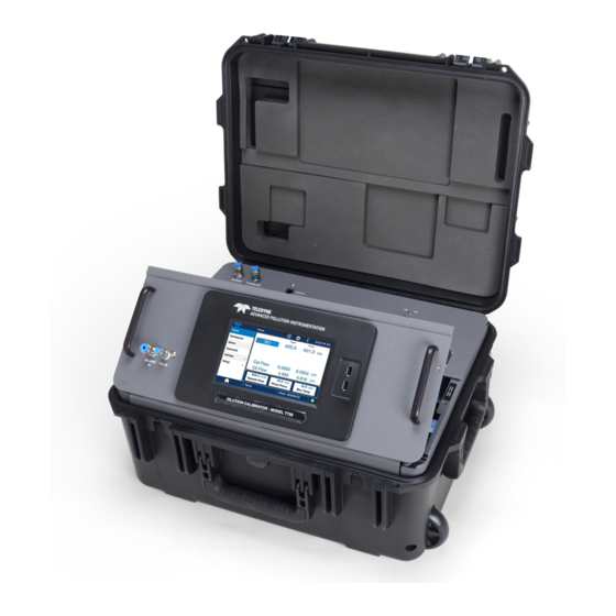
Models T750 and T750U
Copyright 2020-2022
Teledyne API (TAPI)
User Manual
Portable Calibrators
with NumaView™ Software
TELEDYNE API (TAPI)
9970 CARROLL CANYON ROAD
SAN DIEGO, CALIFORNIA 92131-1106
USA
Toll-free Phone:
Phone:
Fax:
Email:
Website:
800-324-5190
858-657-9800
858-657-9816
api-sales@teledyne.com
http://www.teledyne-api.com/
083730750B DCN8606
09 November 2022
Advertisement
Table of Contents
Troubleshooting

Related Manuals for Teledyne T750


Summary of Contents for Teledyne T750
- Page 1 User Manual Models T750 and T750U Portable Calibrators with NumaView™ Software TELEDYNE API (TAPI) 9970 CARROLL CANYON ROAD SAN DIEGO, CALIFORNIA 92131-1106 Toll-free Phone: 800-324-5190 Phone: 858-657-9800 Fax: 858-657-9816 Email: api-sales@teledyne.com Website: http://www.teledyne-api.com/ Copyright 2020-2022 083730750B DCN8606 Teledyne API (TAPI)
- Page 3 NOTICE OF COPYRIGHT © 2020-2022 Teledyne API (TAPI). All rights reserved. TRADEMARKS All trademarks, registered trademarks, brand names or product names appearing in this document are the property of their respective owners and are used herein for identification purposes only.
- Page 4 SAFETY MESSAGES Important safety messages are provided throughout this manual for the purpose of avoiding personal injury or instrument damage. Please read these messages carefully. Each safety message is associated with a safety alert symbol, any of which may be found throughout this manual and inside the instrument. The symbols with messages are defined as follows: WARNING: Electrical Shock Hazard HAZARD: Strong oxidizer...
- Page 5 Note that the safety of a system that may incorporate this product is the end user’s responsibility. Technical Assistance regarding the use and maintenance of this instrument or any other Teledyne API product is available by contacting Teledyne API’s Technical Support Department: Telephone: 800-324-5190 Email: sda_techsupport@teledyne.com...
- Page 6 CONSIGNES DE SÉCURITÉ Des consignes de sécurité importantes sont fournies tout au long du présent manuel dans le but d’éviter des blessures corporelles ou d’endommager les instruments. Veuillez lire attentivement ces consignes. Chaque consigne de sécurité est représentée par un pictogramme d’alerte de sécurité; ces pictogrammes se retrouvent dans ce manuel et à...
- Page 7 MISE EN GARDE Ce produit ne doit être installé, mis en service et utilisé qu’aux fins et de la manière décrites dans le présent manuel. Si vous installez, mettez en service ou utilisez cet instrument de manière incorrecte autre que celle indiquée dans ce manuel ou sous la direction de notre équipe de soutien technique, un comportement imprévisible pourrait entraîner des conséquences potentiellement dangereuses.
- Page 8 PRODUCT RETURN All units or components returned to Teledyne API should be properly packed for handling and returned freight prepaid to the nearest designated Service Center. After the repair, the equipment will be returned, freight prepaid.
-
Page 9: Table Of Contents
TABLE OF CONTENTS INTRODUCTION ....................... 15 1.1. T750 Specifications ........................16 1.2. T750U Specifications ........................17 1.3. Compliance and Certifications ......................18 GETTING STARTED ....................19 2.1. Unpacking ............................19 2.2. Ventilation and Clearance ......................20 2.3. Instrument Layout ........................... 20 Input and Control Panel ...................... - Page 10 Setup>Vars (Variables) ......................69 Setup>Homescreen ........................69 Setup>Digital Outputs (Status) ....................70 Setup>Sequences ........................70 Setting up Control Inputs for a Sequence ................. 73 Setting up Control Outputs for a Sequence ..............74 Activating, Editing, Deleting Sequences ................74 Setup>Levels ..........................75 Editing/Deleting Levels .....................
- Page 11 Setup and Calibration of O Photometer ................107 Photometer Zero Calibration ................... 110 Photometer Span Calibration ..................110 Photometer (Option in T750) Gas Flow Calibration ............111 Photometer Backpressure Compensation Calibration ............112 6.3. Calibrating the O Generator (Option in T750) ................113 6.4.
- Page 12 CPU ............................147 RS-232 Communications, General Troubleshooting ............148 Temperature Problems ......................148 Box / Chassis Temperature ..................148 Photometer Sample Chamber Temperature ..............148 UV Lamp Temperature ....................148 Ozone Generator Temperature ..................149 8.5. Troubleshooting the O Photometer ..................... 149 Dynamic Problems with the O Photometer ................
- Page 13 Figure 2-10. Jumper and Cables for Multidrop Mode ................. 32 Figure 2-11. RS-232-Multidrop PCA Host/Calibrator Interconnect Diagram ..........33 Figure 2-12. Set up for T750 – Connecting the Basic T750 to a Sample Manifold ........36 Figure 2-13. Connections to a Sample Gas Manifold ................. 37 Figure 2-14.
- Page 14 Generator Calibration Setup .................... 113 Figure 6-11. Pressure Monitor Points, T750 Basic Unit ................115 Figure 6-12. Pressure Monitor Points, T750 with O3 Options and Multiple Cal MFCs Installed ....115 Figure 6-13. PSIG Pressure Ca ........................ 116 Figure 6-14. In-Hg Pressure Cal for O Photometer Option ..............
- Page 15 Table 2-3. Status Output Pin Assignments ....................26 Table 2-4. Control Input Pin Assignments ....................26 Table 2-5. Control Output Pin Assignments ....................28 Table 2-6. Valve States for T750 Calibrator with Optional O Generator........... 42 Table 2-7. Valve States with Optional O Generator and Photometer (Options in T750) ......
- Page 16 Table 8-11. Control Outputs Pin Assignments and Corresponding Functions Check ......147 Table 9-1. Power Distribution Board Status LEDs ..................166 Table 9-2. Photometer Measurement / Reference Cycle ................. 175 APPENDIX APPENDIX – INTERCONNECT DIAGRAM 083730750B DCN8606...
-
Page 17: Introduction
The standard T750U has all these features and is designed for producing stable ozone concentrations not only in a high range mode similar to the T750, but also in a low range or fractional mode for producing much lower levels of ozone down to 3 ppb. -
Page 18: T750 Specifications
T750 S 1.1. PECIFICATIONS Specifications are based on constant conditions. Specifications are subject to change without notice. Table 1-1. T750 System Specifications PARAMETER SPECIFICATION Flow Measurement Accuracy ± 1.0% of Full Scale Repeatability of Flow Control ± 0.2% of Full Scale Linearity of Flow Measurement ±... -
Page 19: T750U Specifications
Table 1-2. T750 Options Specifications PARAMETER SPECIFICATION T750 Ozone Generator Option Maximum Output 5.5 ppm SLPM Minimum Output 100 ppb SLPM Response Time: 180 seconds to 98% T750 O Photometer Option Full Scale Range 0 - 100 ppb to 0 - 10 ppm (user selectable) Precision 1.0 ppb... -
Page 20: Compliance And Certifications
PARAMETER SPECIFICATION Installation Category (Over Voltage Category ) II Pollution Degree 2 Environmental Conditions Intended for Indoor Use Only at Altitudes ≤ 2000m Dimensions (H x W x D) 9” x 17” x 21” (229 mm x 432 mm x 533 mm) 46.6 lbs (21.14 kg) 3-MFC Weight 45.1 lbs (20.46 kg) 2-MFC... -
Page 21: Getting Started
Warranty page in this manual, page vi. 1. Before opening, inspect the received package(s) for external shipping damage. If damaged, please advise the shipper first, then Teledyne API. 2. Remove the calibrator from its shipping carton. -
Page 22: Ventilation And Clearance
Figure 2-2 shows the display screen, the orientation to which is described in Section 3.2.1, Figure 3-1. (The Communications and Output panel is presented in Section 2.3.2). Figure 2-1. Control/Display and Input Panel (shown with Model T750 label) 083730750B DCN8606... -
Page 23: Figure 2-2. Display Screen And Touch Control
Figure 2-2. Display Screen and Touch Control The Input and Control Panel liquid crystal display (LCD) screen includes touch control. Upon calibrator start-up, the LCD shows a splash screen and other initialization indicators before the main display appears. CAUTION – AVOID DAMAGING TOUCHSCREEN Do not use hard-surfaced instruments such as pens to operate the touch screen 083730750B DCN8606... -
Page 24: Communications And Output Panel
OMMUNICATIONS AND UTPUT ANEL Figure 2-3. Communications and Output Panel Table 2-1. Communications and Output Panel Description COMPONENT FUNCTION Exhaust gas from ozone generator (and from photometer option if installed) – EXHAUST must be vented out of area. CAL GAS OUT Outlet for calibration gas For cooling: pulls ambient air through chassis from side vents;... -
Page 25: Internal Layout
NTERNAL AYOUT Figure 2-4 shows the internal layout of the calibrator. Figure 2-4. Internal Layout (components labeled “option” are standard in T750U) 083730750B DCN8606... -
Page 26: Connections And Startup
2.4. ONNECTIONS AND TARTUP This section presents the electrical (Section 2.4.1) and pneumatic (Section 2.4.2) connections for setting up and preparing the instrument for initial startup, which is presented in Section 2.5). LECTRICAL ONNECTIONS To maintain compliance with EMC standards, it is required that Note the power cord length be no greater than 3 meters. -
Page 27: Connecting The Analog Output Channel
Connecting the Analog Output Channel The analog output channel must be set by the user who can map it to any one of several functions, such as concentration value, temperatures, pressures, etc. The output signals range between 0 and 5 VDC. To access these signals attach a strip chart recorder and/or data-logger to the analog output connector on the communications and output panel of the calibrator. -
Page 28: Connecting The Control Inputs (Digital Inputs)
Table 2-2. Status Output Pin Assignments OUTPUT # STATUS DEFINITION CONDITION User-selected Emitter Bus The emitters of the transistors on pins 1 to 8 are bussed together. (blank) No connection DC POWER + 5 VDC Digital Ground The ground level from the calibrator’s internal DC power supplies. Connecting the Control Inputs (Digital Inputs) The calibrator is equipped with 12 digital control inputs that can be used to initiate various user programmable calibration sequences and can be turned ON or OFF in the... -
Page 29: Figure 2-7. Digital Control Input Connectors
Example of Local Power Connections Example of External Power Connections 11 12 11 12 5 VDC Power Supply Figure 2-7. Digital Control Input Connectors 083730750B DCN8606... -
Page 30: Connecting The Control Outputs (Digital Outputs)
Connecting the Control Outputs (Digital Outputs) The calibrator is equipped with 12 opto-isolated, digital control outputs, which may be used to interface with devices that accept logic-level digital inputs, such as programmable logic controllers (PLCs), data loggers, or digital relays/valve drivers. These outputs are accessed via a 14-pin connector on the calibrator’s communications and output panel and can be activated in any of three places in the Setup>Sequence menu (see Section 4.2.7.4 for instructions on assigning the control outputs to specific calibration... -
Page 31: Figure 2-9. Connector Pin-Outs For Rs-232 Mode
DCE devices receive data on pin 3 and transmit data on pin 2. Figure 2-9. Connector Pin-Outs for RS-232 Mode Teledyne API offers two mating cables, one of which should be applicable for your use: P/N WR000077, a DB-9 female to DB-9 female cable, 6 feet long. Allows connection of the serial ports of most personal computers. - Page 32 Check cables acquired from sources other than Teledyne API for pin assignments before using. To assist in properly connecting the serial ports to either a computer or a modem, there are activity indicators just below the RS-232 port.
- Page 33 For information on preventing ESD damage, see Fundamentals of ESD manual, PN 04786, available on our website at http://www.teledyne-api.com under Help Center>Product Manuals in the Special Manuals section. In each instrument with the Multidrop option there is a shunt jumpering two pins on the serial Multidrop and LVDS printed circuit assembly (PCA), as shown in Figure 2-10.
-
Page 34: Figure 2-10. Jumper And Cables For Multidrop Mode
Figure 2-10. Jumper and Cables for Multidrop Mode If you are adding an instrument to the end of a previously Note configured chain, remove the shunt between Pins 21 – 22 of JP2 on the Multidrop/LVDS PCA in the instrument that was previously the last instrument in the chain.). -
Page 35: Figure 2-11. Rs-232-Multidrop Pca Host/Calibrator Interconnect Diagram
Note instrument at a time, each by its unique ID (see step 7 above). Teledyne API recommends setting up the first link, between the Host and the first calibrator, and testing it before setting up the rest of the chain. -
Page 36: Pneumatic Connections
If the calibrator is also equipped with an internal photometer, the zero air source • supply gas must be capable of a continuous rate of flow of at least 1.1 SLPM. Zero Air can be purchased in pressurized canisters or created using a Teledyne API’s Model 701 Zero Air Generator. About Calibration Gas Calibration gas is a gas specifically mixed to match the chemical composition of the type of gas being measured at near full scale of the desired measurement range. -
Page 37: Connecting Diluent Gas To The Calibrator
4 SLPM x 1.5 = 6 SLPM = Total Gas Flow Rate If the T750 calibrator is configured so that the cal gas flow rate is 2 SLPM (therefore the Diluent Flow Rate would need to be set at 4 SLPM) the Calibration Gas ratio would 6 SLPM ÷... -
Page 38: Connecting Gas Outputs From The Calibrator
Teledyne API Gas Analyzer Figure 2-12. Set up for T750 – Connecting the Basic T750 to a Sample Manifold To determine if the gas flow on the vent line is ≥ 5 SLPM, subtract the gas flow for each instrument connected to the outlets of the T750 from the TOTAL FLOW setting for the calibrator (see Section 2.5.5). -
Page 39: Figure 2-13. Connections To A Sample Gas Manifold
ALIBRATOR TO A AMPLE ANIFOLD Use this setup when connecting the T750 calibrator to an analyzer network using a sample manifold. In this case, the sampling cane and the manifold itself act as the vent for the T750. SAMPLING CANE... -
Page 40: Figure 2-14. Connections To Calibration Manifold
If Gas flow on this line is ≥ 5 SLPM MANIFOLD the minimum O.D. must be 3/8 inch T750 output flow rate must be greater than 5 SLPM. Minimum O.D. must be 3/8 inch Figure 2-14. Connections to Calibration Manifold •... -
Page 41: Figure 2-15. Connections To A Dual Span Gas / Zero Air Manifold
Note single calibration manifold described previously with the following two exceptions: • The T750 total gas flow rate (Cal Gas Flow Rate + Diluent Flow Rate) out should be greater than the Total Flow requirements of the entire system. • The manifolds as shown in the above drawing are oriented to simplify the drawing. -
Page 42: Pneumatic Flow Diagrams
Mass Flow Controller Figure 2-16. T750 Pneumatic Diagram – Base Unit The standard T750 Portable Calibrator is equipped with one calibration gas mass flow controller (flow rate 0 – 100 cm /min) and one diluent gas mass flow controller (flow rate 0-10 SLPM). -
Page 43: Flow Diagrams With Other Pneumatic Connections
Additionally, a glass mixture volume, designed to meet US EPA guidelines for Gas Phase Titration (GPT), is included with this option. This chamber, in combination with the O generator, allows the T750 to use the GPT technique to more precisely create NO calibration mixtures. -
Page 44: Table 2-6. Valve States For T750 Calibrator With Optional O Generator
ENERATOR WITH HOTOMETER PTION The photometer option increases the accuracy of the T750 calibrator’s optional O generator by directly measuring O content of the gas output by the generator. The photometer’s operation is based on the principle that ozone molecules absorb UV light of a certain wavelength. -
Page 45: Figure 2-18. Flow With O
In BENCH mode the intensity of the O generator’s UV lamp is controlled (and therefore the concentration of the O created) by the T750’s CPU based on the actual O concentration measurements made by the photometer. The O photometer option requires that the O generator also be installed. -
Page 46: Table 2-7. Valve States With Optional O Generator And Photometer (Options In T750)
In an instrument with multiple MFCs the CPU chooses which MFC to use depending on the target gas flow requested. When generating O or in GPT Pre-Set mode, the photometer pump is the primary creator of gas flow through the T750. Flow rates are controlled by critical flow orifice(s) located in the gas stream... -
Page 47: Figure 2-19. Basic T750 With Multiple Calibration Gas Mfcs
An optional third mass flow controller can be added on the calibration gas stream. When this option is installed, the T750 has both calibration gas MFCs on the same gas stream, installed in parallel (see Figure 2-19 and Figure 2-20). The calibrator turns on the MFC with the lowest flow rate that can accommodate the requested flow and can therefore supply the most accurate flow control. -
Page 48: Figure 2-20. Flow With Multiple Cal Gas Mfcs And O Generator And Photometer (Options In T750)
OUTLET CAL GAS INLET Valve On Output Panel GAS INPUT MANIFOLD EXHAUST Cal Gas Mass Flow Controller 2 CAL GAS Volume OUTPUT Figure 2-20. Flow with Multiple Cal Gas MFCs and O Generator and Photometer (options in T750) 083730750B DCN8606... -
Page 49: Startup, Functional Checks, And Initial Calibration
2.5. TARTUP UNCTIONAL HECKS NITIAL ALIBRATION Ensure that you are familiar with the principles of operation by reading Section 9. After making all of the electrical and pneumatic connections, turn on the instrument. The exhaust fan (and pump if photometer options is installed) should start immediately. A sequence of status screens (Figure 2-21) appear on the display, followed by the Home page (Figure 2-22) with the calibrator in STANDBY mode after completing the boot-up sequence. -
Page 50: Alerts: Warnings And Other Messages
LERTS ARNINGS AND THER ESSAGES The Alerts page (Figure 2-23) shows the status of any active warning conditions or user- configured Events. (Section 3.2.3 provides more detailed information about Alerts, and Section 3.3.2 addresses Events). Alerts can be viewed and cleared via either the Alerts menu or the Alerts shortcut (Caution symbol, bottom right corner of the screen). -
Page 51: Calibration Gas Setup
Alternatively, both bottles can be assigned user defined names; e.g. CO2A and CO2B User defined gas names are added to the T750’s gas library and will appear as choices during the various calibrator operations along with the default gas names listed in the interface. -
Page 52: Selecting An Operating Mode For The O Generator
ETUP The default total gas flow rate for the T750 Portable Calibrator is 2 SLPM. The calibrator uses this flow rate, along with the concentrations programmed into the calibrator for the component gas cylinders during set up, to compute individual flow rates for both diluent gas and calibration source gases in order to produce calibration mixtures that match the desired output concentrations. -
Page 53: Start Generating
TART ENERATING Once startup is initiated and functions are checked and working properly, the portable calibrator is ready to generate ozone at the default flow as set up at the factory: Figure 2-24. Basic Generate Initiation If the calibrator’s application requires a different output flow, follow the procedures set forth in Section 2.5.5. - Page 54 This page intentionally left blank. 083730750B DCN8606...
-
Page 55: Configuration
CONFIGURATION This section first provides an overview of the menu (hierarchy with brief descriptions, Section 3.1), followed by an orientation to the main menu pages (Section 3.2), then configuration guidance in the Setup submenus (Section 3.3). 3.1. VERVIEW Table 3-1 describes the menus and provides cross-references for expanded details. Table 3-1. - Page 56 MENU DESCRIPTION LOCATION Diagnostics Provides access to various pages that facilitate troubleshooting. (various) This page shows voltage signals of several analog input parameters, including those from Analog Inputs Section 8.1.3 other instrumentation when the External Analog Inputs Option is installed. Shows voltage signals for one parameter Analog Outputs (configured through Setup>Analog Outputs,...
- Page 57 MENU DESCRIPTION LOCATION Configure a variety of features and functions through these submenus for Section 3.3 Setup customized operation. Track and record concentration and calibration data and Section 3.3.1 selectable diagnostic parameters, the reports for which can be viewed in the Utilities>Datalog View menu and downloaded to a Datalogging flash drive via the Utilities>USB Utilities menu (Section 3.2.5.3).
-
Page 58: Main Menu
3.2. AGES This section describes the pages of the main menu: Home, Dashboard, Alerts, Generate, and Utilities, and drills into further descriptions of the Utilities submenus. The Setup menu warrants a section of its own (Section 3.3) with instructions for configuring the various features and functions of the calibrator. -
Page 59: Dashboard
ASHBOARD The dashboard displays an array of user-selected parameters and their values (Figure 3-2). If there is a graphing icon in the upper right corner of a parameter, pressing that parameter displays a live plot of its readings, as in Figure 3-3. Depending on the number of available parameters selected, the Dashboard can have more than one page. -
Page 60: Alerts
LERTS Alerts are notifications triggered by specific criteria having been met by either factory- defined conditions (standard and not editable) or user-defined Events (Section 3.3.2). The Active Alerts page shows the status of any active warning conditions or Events that have been triggered. -
Page 61: Generate
When all Alerts are cleared, the Alerts menu tab no longer shows the caution symbol, and a green LED replaces the caution symbol in the bottom right corner of the interface (Figure 3-5). However, Alerts can reappear if the conditions causing them are not resolved. For troubleshooting guidance, refer to the instrument’s user manual. -
Page 62: Alerts Log
Alerts Log The Alerts Log holds a history of alerts that were triggered by factory-defined and user- defined Events, such as warnings and alarms. USB Utilities (Downloads and Updates) The USB Utility page serves multiple purposes using a flash drive connected to the instrument’s front panel USB port: •... -
Page 63: Figure 3-8. Das Download Page
Figure 3-8. Das Download Page 2. To copy the data to the flash drive, press the Start button next to “Download DAS Data from Instrument.” (The Cancel button will be enabled). 3. When complete, as indicated in the Status field, the Cancel button becomes the Done button: press Done and then remove the flash drive. -
Page 64: Diagnostics
6. Insert a flash drive into either of the two front panel USB ports. 7. When the Status field indicates that the USB drive has been detected, press the “Upload Configuration to Instrument” Start button. 8. When the Status field indicates that the upload is complete, remove the flash drive. -
Page 65: Setup>Data Logging
>D ETUP OGGING Set up the Data Logger to track and report instrument data based on user-configurable periodic timers or conditional triggers (presented next in this section) or Event-based triggers (Section 3.3.2). In the Setup>Data Logging menu (Figure 3-10), press the ADD button to create a new log (Figure 3-11), or select an existing log from the Data Logging list and press the EDIT or DELETE button to make the desired changes). -
Page 66: Creating A User-Defined Data Log
Creating a User-Defined Data Log Figure 3-12. Datalog Configuration 083730750B DCN8606... -
Page 67: Configuring Trigger Types For The Datalogger
Configuring Trigger Types for the Datalogger ERIODIC RIGGER The Periodic trigger is a timer-based trigger that is used to log data at a specific time interval. Periodic Trigger requires an interval that is set to number of minutes and a start time that is set to date and time. -
Page 68: Setup>Events
>E ETUP VENTS Events are occurrences that relate to any operating function, and are used to define the conditions that will trigger Alerts (Section 3.2.3). Events can provide diagnostic information about the instrument, typically referred to as “Warnings”, or they can provide additional instrument functionality, such as concentration alarms. -
Page 69: Creating User-Defined Events
Creating User-defined Events In the Setup>Events menu (Figure 3-15) press ADD to create a new Event. Figure 3-16 depicts the steps for creating an Event. In the center of the display, the Enabled box allows the choice of whether to track and record the Event. The Visible box allows the choice of whether or not to display the Event in the Alerts tab when it is triggered, although it will still be recorded. -
Page 70: Setup>Dashboard
>D ETUP ASHBOARD The Dashboard can be configured to display an array of parameters and can extend to more than one Dashboard page. To add a parameter for display in the Dashboard, select from the • “Available Tags” column and press the right-pointing button To remove a parameter from the Dashboard, select a tag from the •... -
Page 71: Setup>Vars (Variables)
>V ETUP ARIABLES The calibrator has several user-adjustable software variables, which define certain operational parameters. Select a Var to see a description of its purpose in the pane to the right; press the Edit button to change its setting(s). Figure 3-20. Vars Configuration Page >H ETUP OMESCREEN... -
Page 72: Setup>Digital Outputs (Status)
>D ETUP IGITAL UTPUTS TATUS Specify the function of each Digital Output for status and map it to any of a wide variety of “Signals” present in the instrument. The Digital Outputs 1 thru 8 correspond to pins 1 thru 8 on the rear panel STATUS connector. (MB Relay 1 thru 4 do not apply in the calibrator). -
Page 73: Figure 3-23. Example List Of Configured Sequences
Figure 3-23. Example List of Configured Sequences Figure 3-24. Configuring a Sequence 083730750B DCN8606... -
Page 74: Table 3-2. Automatic Calibration Sequence Set Up Attributes
Table 3-2. Automatic Calibration Sequence Set Up Attributes ATTRIBUTE DESCRIPTION Name Allows the user to create a text string of up to 10 characters identifying the sequence. Timer Enable Check the Enable box to activate an internal automatic timer to initiate sequences using the calibrator’s built in clock. -
Page 75: Setting Up Control Inputs For A Sequence
ATTRIBUTE DESCRIPTION Enable1 is for Status Block 1, which corresponds to the physical CONTROL OUTPUT connector. To configure, press the respective Enable box and check the desired box(es) whose numbers correspond to the Pin numbers. SET STATUS BLOCK Enable 2 is for Status Block 2, which does not correspond to any physical output but is used to communicate status over the serial data port. -
Page 76: Setting Up Control Outputs For A Sequence
Setting up Control Outputs for a Sequence The calibrator’s control outputs allow setting up the calibrator to control devices that accept logic-level digital inputs, such as programmable logic controllers (PLCs), data loggers, or digital relays/valve drivers. They can be used as: 12 separate ON/OFF switches assigned to separate calibration •... -
Page 77: Setup>Levels
>L ETUP EVELS When the calibrator is equipped with a version of firmware that includes support for LEADS, there are a few parameters that can be programmed to carry out a single-step operation called a Level, starting with assigning a number (ID) to identify it. Unlike Sequences, Levels are not time based and do not include characteristics such as start time or duration;... -
Page 78: Editing/Deleting Levels
Figure 3-27. Levels Programming and Editing Editing/Deleting Levels To edit an existing Level, navigate to the Setup>Levels menu, select a Level and start with Step 3 above. To delete an existing Level, navigate to the Setup>Levels menu, select a Level and press the Delete button. -
Page 79: Setup>Analog Outputs
>A ETUP NALOG UTPUTS The Setup>Analog Outputs menu provides the ability to configure and calibrate the analog output that was connected per Section 2.4.1.2. It can set by the user to carry the signal level of any one of the parameters listed in the Setup>Analog Outputs>Analog Output Cfg menu and will output an analog VDC signal that rises and falls in relationship to the value of that parameter. -
Page 80: Analog Output Voltage Range Configuration
Analog Output Voltage Range Configuration In its standard configuration, the analog outputs are set to output 0 – 5 VDC signals. Several other output ranges are available (see Table 3-3). Each range is usable from -5% to + 5% of the rated span. Table 3-3. -
Page 81: Figure 3-30. Setup For Manually Calibrating The Analog Output
MANUAL For highest accuracy, the voltages of the analog outputs can be manually calibrated with a voltmeter connected across the output terminals (see Figure 3-30) and by changing the actual output signal level using the Manual Adjust buttons in 100, 10 or 1 count increments (Figure 3-31). -
Page 82: Setup>Instrument
>I ETUP NSTRUMENT The Instrument page shows product information and configurable instrument settings. Figure 3-32. Setup>Instrument Menu >C ETUP OMMUNICATIONS This menu is for specifying the various communications configurations. COM1/COM2 Configure the instrument’s COM1 or COM2 ports to operate in modes listed and described in Table 3-5. -
Page 83: Tcp Port1
MODE DESCRIPTION Enable/disable multidrop mode for multi-instrument configuration on a single Multidrop communications channel. Multidrop requires a unique ID for each instrument in the chain (Setup>Vars>Instrument ID). Select odd, or even, or no parity (typically set in conjunction with Data Bits and Parity Stop Bits). -
Page 84: Setup>Gas
Figure 3-33. Communications Configuration, Network Settings Table 3-6. LAN/Ethernet Configuration Properties PROPERTY DESCRIPTION A string of four packets of 1 to 3 numbers each (e.g. 192.168.76.55.) is IP address the internet protocol address of the instrument itself. A string of four packets of 1 to 3 numbers each (e.g. 255.255.252.0) number that masks an IP address, and divides the IP address into network address and host address and identifies the LAN to which the Subnet Mask... -
Page 85: Operation
The last step of any calibration sequences (Section 3.3.7) • should always be the STANDY instruction. Table 4-1 shows the status of the T750’s various pneumatic components when the calibrator is in STANDBY mode. Figure 4-1 shows the pneumatic flow path during Standby mode, including options. -
Page 86: Generate Mode
The Generate menu is used to generate the desired calibration gas mixtures based on the source gas concentration entered during initial setup (Section 3.3.12, Setup>Gas). With the O generator (if option installed in T750), various concentrations of O can be generated, and the Gas Phase Titration feature becomes available. -
Page 87: Figure 4-3. Gas Flow Through Basic T750 In Generate Mode
Mass Flow Controller Figure 4-3. Gas Flow through Basic T750 in GENERATE Mode Table 4-2 shows the status of the T750’s various pneumatic components when the calibrator is in GENERATE mode: Table 4-2. Status of Internal Pneumatics During GENERATE Mode... -
Page 88: Figure 4-4. Gas Flow Through T750 With O
On Output Panel GAS INPUT MANIFOLD EXHAUST Cal Gas Mass Flow Controller 1 CAL GAS Volume OUTPUT Figure 4-4. Gas Flow through T750 with O Options when Generating Non-O Source Gas Instrument Chassis Flow Control PHOTOMETER BENCH (1.0 LPM) Pressure... -
Page 89: Generate>Auto
This allows control of the mixing ratio and total calibration gas flow rate. In addition, if the T750 calibrator is equipped with the optional O generator, and O is to be included in the calibration mixture (e.g. -
Page 90: Determining The Source Gas Flow Rate
The minimum total flow should equal 150% of the flow Note requirements of all of the instruments to which the T750 will be supplying calibration gas. Example: If the T750 will supply calibration gas mixtures simultaneously to a system of three analyzers, each requiring 2 SLPM, the Total Flow output should be set at: (2 + 2 + 2) x 1.5 = 9.000... -
Page 91: Generate>Gptz, Gptps, Gpt: Understanding Gas Phase Titration (Gpt)
10% of the lowest rated MFC to 100% of the combined full-scale ratings for both mass flow controllers. The T750 will automatically select the MFC with the lowest flow rate that can accommodate the requested flow, thereby affording the most precise flow control. -
Page 92: Gpt Theory
SLPM) and the GPT chamber’s volume is known, once the TOTAL GAS FLOW requirements, the source concentration of NO, and the target concentration for the O generator are entered into the calibrator’s software. The T750 adjusts the NO flow rate and diluent (zero air) flow rate to create the appropriate NO concentration at the output. -
Page 93: Determining The Total Flow For Gpt Calibration Mixtures
T750 will be supplying calibration gas. Example: If the T750 will be expected to supply calibration gas mixtures simultaneously to a system composed of three analyzers, each requiring 2 SLPM, the proper Total Flow output should be set at: (2 + 2 + 2) x 1.5 = 9.000 SLPM It is not recommended to set any flow rate to <10% or >100%... -
Page 94: Figure 4-8. Gas Flow Through T750 With O
Mass Flow Controller 1 CAL GAS Volume OUTPUT Figure 4-8. Gas Flow through T750 with O Options when in GPTZ Mode In the Generate page, press the GPTZ button and configure the parameters according to: NO source gas concentration •... -
Page 95: Generate>Gptps: Performing A Gpt Pre-Set (To Be Run After Gptz And Prior To Gpt)
NO gas that would normally be used. The following table and figures show the status of the T750’s internal pneumatic components and internal gas flow when the instrument is in GPTPS generating mode. -
Page 96: Figure 4-10. Gas Flow Through T750 With O
Mass Flow Controller 1 CAL GAS Volume OUTPUT Figure 4-10. Gas Flow through T750 with O Options when in GPTPS Mode In the Generate page, press the GPTPS button and configure the parameters according to: • NO source gas concentration •... -
Page 97: Generate>Gpt: Performing A Gas Phase Titration Calibration
It is required that a GPT Pre-Set (GPTPS, Section 4.2.5) be performed before initiating any GPT gas generation. The following table and Figure show the status of the T750’s internal pneumatic components and internal gas flow when the instrument is in GPT generating mode. -
Page 98: Generate>Sequence: Automatic Operation Using Sequences
In the Generate page, press the GPT button and configure the parameters according to: NO source gas concentration and units • Target O3 concentration (equal to the target NO concentration to be • generated) and units Total Flow in SLPM for the mixture output •... -
Page 99: Activating A Sequence With The External Digital Control Inputs
Because LEADS was originally developed for use with TNRCC using Dasibi 5008 calibrators, the LEADS version of the T750/T750U includes support for Dasibi “Dot” serial data commands and operational “LEVELs”. (For more information on the LEADS system, please go to http://www.meteostar.com/). -
Page 100: Activating Levels
EXAMPLE: ^A.xxx!nn A T750/T750U equipped with LEADS software can be simultaneously operated over the same COM port using standard Teledyne API’s serial data commands. Activating Levels Levels are individually started and stopped either by an operator locally by using the touchscreen menu or remotely through a serial data operation over the RS-232 or Ethernet ports. -
Page 101: Communications And Remote Operation
COMMUNICATIONS AND REMOTE OPERATION This instrument’s output and communications panel connections include an Ethernet port and serial communications ports. This section provides pertinent information regarding communication equipment, the communications ports, and communications protocol. Data acquisition is set up through the Datalogger (Section 3.3.1). 5.1. -
Page 102: Serial Communication: Rs-232
A code-activated switch (CAS), can also be used on either port to connect typically between 2 and 16 send/receive instruments (host computer(s) printers, data loggers, analyzers, monitors, calibrators, etc.) into one communications hub. Contact Teledyne API Sales (front cover, this manual) for more information on CAS systems. -
Page 103: Modbus Protocol And Com Port Configuration
The following set of instructions assumes that the user is familiar with MODBUS communications, and provides minimal information to get started. For additional instruction, please refer to the Teledyne API MODBUS manual, PN 06276. Also refer to www.modbus.org for MODBUS communication protocols. - Page 104 This page intentionally left blank. 083730750B DCN8606...
-
Page 105: Calibration And Verification
CALIBRATION AND VERIFICATION Basic electronic calibration of the Calibrator is performed at the factory. Normally there is no need to perform this factory calibration in the field however, the performance of several of the instrument’s key subsystems should be verified periodically and if necessary adjusted. -
Page 106: Setup For Verifying And Calibrating The Mfcs
Table 6-1. Examples of MFC Calibration Points MFC FULL SCALE DRIVE 1.0 SLPM 3.0 SLPM 5.0 SLPM 10.0 SLPM POINT VOLTAGE MFC TARGET OUTPUT 000 mV 0.000 0.000 0.000 0.000 250 mV 0.050 0.150 0.250 0.500 500 mV 0.100 0.300 0.500 1.000 750 mV... -
Page 107: Verifying And Calibrating The O Photometer (Option In T750)
Setup illustration and instructions for verification are presented in Section 6.2.1. Setup for calibration differs and instructions are presented in Section 6.2.2. In either case, an external source of zero air (such as a Teledyne API’s Model 701 Zero Air Generator) is required. 083730750B DCN8606... -
Page 108: Setup And Verification Of O Photometer Performance
Connect to same PHOTOMETER zero air source as Zero Port the T750 Figure 6-3. Set up for Verifying O Photometer To verify the performance of the internal photometer, place the calibrator in Standby mode (in Generate menu), and perform the following steps (refer to Figure 6-4): 1. -
Page 109: Setup And Calibration Of O Photometer
Figure 6-4. O Photometer Performance Verification ETUP AND ALIBRATION OF HOTOMETER This procedure requires external sources for zero air and O Note as well as an external reference photometer. Calibrating the internal photometer requires a different setup than that for verification. There are two ways to make the connections between the instruments for calibration: either with direct connections or with calibration manifolds. -
Page 110: Figure 6-5. External Photometer Calibration Setup With Direct Connections
External Zero Air Source REFERENCE PHOTOMETER External O Source PHOTO IN PHOTO OUTLET (internal) Capped PHOTO ZERO IN PHOTO ZERO OUT (internal) Capped Vent line EXHAUST Max Length=3 meters ( or 10 feet) CYL IN Calibration Vent CALGAS Source Gas connections were presented in the Pneumatic Connections If the gas flow on this... -
Page 111: Figure 6-6. External Photometer Calibration Setup With Calibration Manifolds
External Zero Air External O Source Source REFERENCE PHOTOMETER To other calibrators or instruments PHOTOMETER INLET Capped PHOTOMETER OUTLET Max Length=3 meters ( or 10 feet) PHOTOMETER ZERO IN Vent line PHOTOMETER ZERO OUT Capped Max Length=3 meters ( or 10 feet) EXHAUST Calibration Source Gas connections... -
Page 112: Photometer Zero Calibration
Figure 6-7. O Photometer Bench Cal Page Photometer Zero Calibration To set the zero point offset for the portable calibrator’s photometer: 1. Ensure that the calibrator is in Standby mode (Generate menu). 2. Navigate to the Utilities>Diagnostics>Bench Cal menu. 3. Press either the Zero button if using the internal O generator or the XZero button if using an external O generator. -
Page 113: O 3 Photometer (Option In T750) Gas Flow Calibration
T750) G HOTOMETER PTION IN ALIBRATION The photometer sample gas flow rate is measured directly by a flow sensor located on the pressure / flow sensor PCA. A slope factor, stored in the calibrator’s memory the last time a Photo Flow calibration was performed, is applied to the reading from that sensor. -
Page 114: O 3 Photometer Backpressure Compensation Calibration
HOTOMETER ACKPRESSURE OMPENSATION ALIBRATION Any time there is a pneumatic configuration change, there is risk of impacting the internal measure/reference pressure. To compensate for this, a backpressure compensation calibration is required after each change. Set the calibrator to generate ozone in the Generate menu at the flow rate intended for operation. -
Page 115: Calibrating The O
An external reference photometer is required for this procedure. Figure 6-10 shows the setup connections. REFERENCE PHOTOMETER PHOTOMETER INLET Capped Operator must vent T750 CALGAS OUT gas line to PHOTOMETER OUTLET outside of room, with at least PHOTOMETER ZERO IN Capped 3 ft of 1/4 inch tubing. -
Page 116: Calibrating Gas Pressure Sensors
6.4. ALIBRATING RESSURE ENSORS Note The calibration procedures presented in this section require an independent, calibrated pressure meter/monitor. The portable calibrator has several sensors that monitor the pressure of the gases flowing through the instrument. The data collected by these sensors are used to compensate the final concentration calculations for changes in atmospheric pressure and are stored in the CPU’s memory. -
Page 117: Figure 6-11. Pressure Monitor Points, T750 Basic Unit
PRESSURE SENSOR PHOTOMETER OUTLET Valve On Output Panel GAS INPUT MANIFOLD EXHAUST Cal Gas Mass Flow Controller 2 Pressure Monitor CAL GAS Volume OUTPUT Figure 6-12. Pressure Monitor Points, T750 with O3 Options and Multiple Cal MFCs Installed 083730750B DCN8606... -
Page 118: Calibrating The Diluent, Cal Gas, And O Generator Option Pressure Sensors
ALIBRATING THE ILUENT ENERATOR PTION RESSURE ENSORS The procedures for setting up the O Photometer option for its Note pressure sensor calibration differ slightly and are presented in Section 6.4.3. (It does still require the independent, calibrated pressure meter/monitor). 1. Turn off the calibrator and open its panels. 2. -
Page 119: Analog Inputs Calibration
5. Navigate to the Utilities>Diagnostics>Pressure Cal menu and select Photo Press Cal. Figure 6-14. In-Hg Pressure Cal for O Photometer Option 6. In the Actual Pressure field input the value obtained in Step 3. 7. Once entered, press the Calibrate button and confirm in the next window to proceed with the pressure calibration. - Page 120 This page intentionally left blank. 083730750B DCN8606...
-
Page 121: Maintenance And Service
MAINTENANCE AND SERVICE Predictive diagnostic functions including failure warnings and alarms built into the calibrator’s firmware allow the user to determine when repairs are necessary without performing painstaking preventative maintenance procedures. For the most part, the calibrator is maintenance free; there are, however, a minimal number of simple procedures that when performed regularly will ensure that the photometer continues to operate accurately and reliably over its lifetime. - Page 122 This page intentionally left blank. 083730750B DCN8606...
-
Page 123: Table 7-1. Maintenance Schedule
As Needed Tube cleaning Clean Zero Air (Diluent Gas is used with the calibrator Annually or any Perform Verify Flow time the T750’s Flow Check of MFCs internal DAC is recalibrated Annually or after Perform Verify Leak any Maintenance Leak Check... - Page 124 This page intentionally left blank. 083730750B DCN8606...
-
Page 125: Operational Health Checks
The report is generated every 24 hours to the Internet (the “cloud”) where it is available for viewing by Teledyne API technical support personnel. To download the report for your own viewing on a computer or to send to others, insert a flash drive into a front panel USB port and press the Download button, which is enabled when the instrument detects the flash drive. -
Page 126: Manual Reload/Update Procedures
HECK QUIPMENT AND ALIBRATOR ETUP Make sure to have ready: One 1/4” pneumatic cap for the CAL GAS OUT fitting on T750 basic • configuration, Or, for T750 models with the O generator with photometer installed: Two (2) 1/4" Pneumatic caps (for EXHAUST and CAL GAS OUT ports) •... -
Page 127: Figure 7-4. Clamping The Photometer Sensor Input And Pump Output
Refer to Figure 7-4 and Figure 7-5 for the setup instructions, and to Figure 7-6 and Figure 7-7 for illustrations of pneumatic flow in the basic model and with the optional photometer, respectively): 1. Power off the instrument. 2. Use the 1/4" caps to cover the EXHAUST and CALGAS OUT ports on the communications and output panel (Figure 2-3). -
Page 128: Figure 7-5. Internal Vent Location
Mass Flow Controller CAL GAS INLET On Output Panel CAL GAS PRESSURE SENSOR EXHAUST CAL GAS OUTPUT GAS INPUT MANIFOLD Cal Gas Mass Flow Controller Figure 7-6. Gas Flow for Auto-Leak Check Procedure of Base Model T750 (no Photometer) 083730750B DCN8606... -
Page 129: Returning The Calibrator To Service After Auto Leak Check
Instrument Chassis Clamp points for leak check Flow Control PHOTOMETER BENCH (1.0 LPM) Pressure GAS INPUT Regulator PRESSURE SENSOR DILUENT INLET PHOTOMETER PRESSURE SENSOR DILUENT Photometer Loop GEN / PHOTOMETER Valve PRESSURE / FLOW SENSOR PCA PHOTOMETER INLET Flow Control (800 cm REF/MEAS Valve... -
Page 130: Cleaning Or Replacing The Absorption Tube
7.5. LEANING OR EPLACING THE BSORPTION Although this procedure should never be needed as long as Note the user is careful only to supply the photometer with clean, dry and particulate free zero air, it is included here for those rare occasions when cleaning or replacing the absorption tube may be required. -
Page 131: Adjusting The Photometer Option's Uv Source Lamp
’ UV S 7.6. DJUSTING THE HOTOMETER PTION OURCE This procedure details the steps for adjustment of the UV source lamp in the optical bench assembly. This procedure should be done whenever the PHOTO REFERENCE value drops below 3000 mV. 1. -
Page 132: Replacing The Photometer Option Suv Source Lamp
’ UV S 7.7. EPLACING THE HOTOMETER PTION OURCE This procedure details the steps for replacement of the UV source lamp in the optical bench assembly. This procedure should be done whenever the lamp can no longer be adjusted as described in Section 7.6. -
Page 133: Adjusting Or Replacing The Ozone Generator Uv Lamp
UV L 7.8. DJUSTING OR EPLACING THE ZONE ENERATOR This procedure details the steps for replacement and initial adjustment of the ozone generator lamp. If you are adjusting an existing lamp, skip to Step 8. 1. Turn off the calibrator. 2. - Page 134 This page intentionally left blank 083730750B DCN8606...
-
Page 135: General Troubleshooting & Service
GENERAL TROUBLESHOOTING & SERVICE This section contains a variety of methods for identifying and solving performance problems with the calibrator. CAUTION – TECHNICIAN REQUIRED The operations outlined in this chapter are to be performed by qualified maintenance personnel only. WARNING – ELECTRICAL SHOCK HAZARD •... -
Page 136: Fault Diagnosis With Messages In The Alerts Page
MFC Pressure Warning pressure is - Leak or blockage exists in the T750’s internal pneumatics <15 PSIG or >36 PSIG - Failed CAL GAS or DILUENT pressure sensor - No IZS option installed, instrument improperly configured... -
Page 137: Fault Diagnosis With Dashboard Functions
Regulator Pressure - Incorrectly adjusted O zero air pressure regulator Warning <15 PSIG or >25 PSIG - Leak or blockage exists in the T750’s internal pneumatics - Failed O Generator Input pressure sensor C Bus failure The CPU cannot communicate... -
Page 138: Using The Diagnostic Analog Inputs Function
FUNCTION DIAGNOSTIC RELEVANCE AND CAUSES OF FAULT CONDITIONS. If the Box Temperature is out of range (Box Temperature typically runs ~7°C warmer than ambient temperature), make sure that: Box Temp - The Exhaust-Fan is running. - There is sufficient open space to the side and rear of instrument to allow adequate ventilation. -
Page 139: Using The Signal Outputs For Diagnostics
8.2. SING THE IGNAL UTPUTS FOR IAGNOSTICS The signals available for output over the Analog Output channel can also be used as diagnostic tools. See Section 3.3.9 for instruction on activating the analog output and selecting a function. Table 8-3. Signal Outputs as Diagnostic Tools FULL CAUSES OF EXTREMELY FUNCTION... -
Page 140: Using The Internal Electronic Status Leds
8.3. SING THE NTERNAL LECTRONIC TATUS Several LEDs are located inside the instrument to assist in determining if the calibrators CPU, I C bus and Power distribution board are functioning properly. CPU S TATUS NDICATOR DS5, a red LED, that is located on upper portion of the motherboard, just to the right of the CPU board, flashes when the CPU is running the main program loop. -
Page 141: Troubleshooting With Power Distribution Board Status Leds
Troubleshooting with Power Distribution Board Status LEDs Figure 8-2. Power Distribution Board Status LEDs Used for Troubleshooting Table 8-5. Power Distribution Board Status LED Failure Indications ACTIVATED BY INDICATES DIAGNOSTIC TECHNIQUE DIGITAL OUTPUT GPT Valve Status GPT_VALVE Valve should audibly change states. If not: •... -
Page 142: Subsystem Checkout
8.4. UBSYSTEM HECKOUT The preceding sections of this manual discussed a variety of methods for identifying possible sources of failures or performance problems within the calibrator. In most cases, this includes a list of possible components or subsystems that might be the source of the problem. -
Page 143: Figure 8-3. Location Of Dc Power Test Points On Power Distribution Board
Figure 8-3. Location of DC Power Test Points on Power distribution board Table 8-6. DC Power Test Point and Wiring Color Codes NAME TEST POINT# TP AND WIRE COLOR Dgnd Black Agnd Green +15V Blue -15V Yellow +12R Purple +12V Orange A voltmeter should be used to verify that the DC voltages are correct per the values in the table below, and an oscilloscope, in AC mode, with band limiting turned on, can be used... -
Page 144: I 2 C Bus
Table 8-7. DC Power Supply Acceptable Levels CHECK POWER DISTRIBUTION BOARD POWER TEST POINTS SUPPLY MIN V MAX V VOLTAGE FROM TEST POINT TO TEST POINT ASSY NAME NAME Dgnd 5.25 Agnd 13.5 Agnd -15V -14V -16V Agnd Agnd Dgnd -0.05 0.05 Chassis... -
Page 145: Power Distribution Board
OWER ISTRIBUTION OARD The Power distribution board can be most easily checked by observing the condition of the status LEDs located along its upper edge (see Section 8.3.2 and Figure 8-2), and observing the Utilities>Diagnostics>Analog Inputs menu (see Section 8.1.3) while toggling each LED ON or OFF. -
Page 146: Photometer O 3 Generator Pressure /Flow Sensor Assembly
HOTOMETER ENERATOR RESSURE ENSOR SSEMBLY This assembly is present in calibrators with the O generator and/or photometer installed. The pressure sensor/flow sensor PCA, located on the inside of the outputs panel next to the Motherboard, can be checked with a voltmeter. The following procedure assumes that the wiring is intact and that the motherboard and the power supplies are operating properly: ASIC OPERATION... -
Page 147: Motherboard
OTHERBOARD A/D Functions The simplest method to check the operation of the A-to-D converter on the motherboard is to use the Analog Inputs page in the Utilities>Diagnostics menu to check the two A/D reference voltages and input signals that can be easily measured with a voltmeter. 1. -
Page 148: Status Outputs (Digital Output Pins 1 - 8)
Table 8-9. Analog Output Test Function - Nominal Values Voltage Outputs FULL SCALE OUTPUT OF VOLTAGE RANGE 100MV SIGNAL NOMINAL OUTPUT VOLTAGE 20 mV 40 mV 60 mV 80 mV 100 mV If one or more of the readings fails to be within range, it is likely that there has been a failure of the either or both of the DACs and their associated circuitry on the motherboard. -
Page 149: Control Outputs (Digital Output Pins 1 - 12)
The control input bits can be tested by applying a trigger voltage to an input and watching changes in the status of the associated function under the Utilities>Diagnostics menu: EXAMPLE: to test the “1” control input: 1. Under the Utilities>Diagnostics menu scroll to the input for CONTROL_IN_1. 2. -
Page 150: Communications, General Troubleshooting
ENERAL ROUBLESHOOTING Teledyne API calibrators use the RS-232 communications protocol to allow the instrument to be connected to a variety of computer-based equipment. RS-232 has been used for many years and as equipment has become more advanced, connections between various types of hardware have become increasingly difficult. -
Page 151: Ozone Generator Temperature
• Assuming that the I C bus is working and that there is no other failure with the Power distribution board, the FET Driver on the Power distribution board may have failed. Using the PHOTO_LAMP HEATER parameter in the Utilities>Diagnostics •... -
Page 152: Noisy Or Unstable O Readings At Zero
Noisy or Unstable O Readings at Zero Check for leaks in the pneumatic system as described in Section 7.2 • Confirm that the Zero gas is free of Ozone. • Confirm that the Source Lamp is fully inserted and that the lamp hold-down •... -
Page 153: Cannot Span
Cannot Span Check for leaks in the pneumatic systems as described in Section 7.2. • Check for proper operation of the meas/ref switching valve as described in • Section 8.5.2. Check for dirty absorption cell and clean or replace as necessary as •... -
Page 154: Troubleshooting The O Generator
8.6. ROUBLESHOOTING THE ENERATOR WARNING – ELECTRICAL SHOCK HAZARD Hazardous voltage present - use caution. The only significant components of the O generator that might reasonable malfunction is the power supply assembly for the UV source lamp and the lamp itself. 1. -
Page 155: Technical Assistance
9970 Carroll Canyon Road San Diego, California 92131-1106 Toll-free Phone: +1 800-324-5190 Phone: +1 858-657-9800 Fax: +1 858-657-9816 Email: api-techsupport@teledyne.com Website: http://www.teledyne-api.com/ Before contacting Technical Support, please complete the problem report available online for electronic submission at http://www.teledyne-api.com/forms/. 083730750B DCN8606... - Page 156 This page intentionally left blank. 083730750B DCN8606...
-
Page 157: Principles Of Operation
MFCn flow rate This dilution process is dynamic. The T750’s CPU not only keeps track of the temperature and pressure of the various gases, but also receives data on actual flow rates of the various MFCs in real time so the flow rate control can be constantly adjusted to maintain a stable output concentration. -
Page 158: Gas Phase Titration Mixtures For Oand No
The GPT chamber’s volume is known, The source concentration of NO is a fixed value, • Once the TOTALFLOW is determined and entered into the T750’s memory and target concentration for the O generator are entered into the calibrator’s software, the T750 adjusts the NO flow rate and diluent (zero air) flow rate to precisely create the appropriate concentration at the output. -
Page 159: Pneumatic Operation
MFCs. ONTROL The precision of gas flow through the T750 Portable Calibrator is centrally critical to its ability to mix calibration gases accurately. This control is established in several ways. -
Page 160: Flow Control Assemblies For O Components
5.00 VDC. A separate 0 to 5 VDC command voltage is also generated that is proportional to the target flow rate requested by the calibrator’s CPU. The 0-5VDC command signal is electronically subtracted from the 0-5VDC flow signal. The amount and direction of the movement is dependent upon the value and the sign of the differential signal. -
Page 161: Internal Gas Pressure Sensors
NTERNAL RESSURE ENSORS The T750 portable calibrator includes a single pressure regulator. Depending upon how many and which options are installed, there are between two and four pressure sensors installed as well. In the basic unit a printed circuit, assembly located near the front of the calibrator near the MFCs includes sensors that measure the pressure of the diluent gas and the source gas currently selected to flow into the calibrator. -
Page 162: Electronic Operation
Teledyne API. It communicates with the user as well as receives data from and issues commands to a variety of peripheral devices via a separate printed circuit assembly called the motherboard. - Page 163 CPU and the calibrator’s other major components. Data are generated by the various subcomponents of the T750 (e.g. flow data from the MFCs, O concentration from the optional photometer). Analog signals are converted into digital data by a unipolar, analog-to-digital converter, located on the motherboard.
-
Page 164: Central Processing Unit (Cpu)
Disk On Module (DOM) The DOM is a 44-pin IDE flash chip with a storage capacity up to 256 MB. It is used to store the computer’s operating system, the Teledyne API firmware, and most of the operational data. Flash Chip This non-volatile, embedded flash chip includes 2MB of storage for calibration data as well as a backup of the calibrator’s configuration. -
Page 165: Power Distribution Board (Relay Pca)
PCA) OWER ISTRIBUTION OARD ELAY The power distribution board (Relay PCA), Figure 9-3, is one of the central switching and power distribution units of the calibrator (see Figure 9-4 for its location). It contains power relays, valve drivers and status LEDs for all heated zones and valves, as well as thermocouple amplifiers, power distribution connectors and the two switching power supplies of the calibrator. -
Page 166: Valve Control
Figure 9-4. Relay PCA Location WARNING – ELECTRICAL SHOCK HAZARD Never remove the AC Cage, which is a safety shield, while the instrument is plugged in and turned on. The contacts of the AC relay sockets beneath the shield carry high AC voltages even when no relays are present. -
Page 167: Heater Control
Heater Control The power distribution board controls the DC heaters related to the O generator and photometer. MOTHER BOARD Converter Thermistor(s) (V/F) e.g. photometer sample gas temp.; photometer UV lamp temp.; O generator lamp temp.; ect.) RELAY PCA Control Logic Generator PHOTOMETER Lamp Heater... -
Page 168: Watchdog Indicator (D1)
When lit, the O generator UV lamp Generator Heater Status heater is on On T750, only applies when photometer option installed. On T750, only applies when O generator option installed. Watchdog Indicator (D1) The most important of the status LEDs on the power distribution board/Relay board is the red I C Bus watchdog LED. -
Page 169: Power Supply And Circuit Breaker
OWER UPPLY AND IRCUIT REAKER The calibrator operates in two main AC power ranges as presented in the specifications table. A 5-ampere circuit breaker is built into the ON/OFF switch. In case of a wiring fault or incorrect supply power, the circuit breaker will automatically turn off the calibrator. The calibrator is equipped with a universal power supply that Note allows it to accept any AC power configuration, within the limits... -
Page 170: Input And Control Panel Touchscreen/Display Interface
9.5. NPUT AND ONTROL ANEL OUCHSCREEN ISPLAY NTERFACE The most commonly used method for communicating with the T753U Portable Calibrator is via the instrument’s Input and Control Panel LCD touchscreen display. The LCD display is controlled directly by the CPU board. The touchscreen is interfaced to the CPU by means of a touchscreen controller that connects to the CPU via the internal USB bus and emulates a computer mouse. -
Page 171: Software Operation
PERATION The calibrator’s core module is a high performance, Vortex 86SX-based microcomputer running Windows CE. Inside Windows CE, special software developed by Teledyne API interprets user commands from the various interfaces, performs procedures and tasks, stores data in the CPU’s various memory devices, and calculates the concentration of the gas being sampled. -
Page 172: O 3 Generator Operation
9.7. ENERATOR PERATION RINCIPLE OF HOTOLYTIC ENERATION Ozone is a naturally occurring substance made up of three atoms of oxygen (O ). Because of its relatively short half-life, ozone cannot be bottled and stored for later use and therefore must always be generated on-site by an ozone generator. The two main principles of ozone generation are Ultraviolet (UV) light and corona discharge. -
Page 173: O 3 Generator Pneumatic Operation
The zero air source must be capable of maintaining a continuous flow rate of at least 100 cm /min unless the photometer (opti0n in the T750) is also installed, in which case the minimum continuous flow rate must be at least 1.1 SLPM. -
Page 174: O 3 Generator Electronic Operation
ENERATOR LECTRONIC PERATION Electronically the O generator and its subcomponents act as peripheral devices operated by the CPU via the motherboard. Sensor signals, such as from the UV lamp thermistor, are routed to the motherboard where they are digitized. Digital data are sent by the motherboard to the calibrator’s CPU and, where required, are stored in either flash memory or on the CPU’s Disk-on-Module. -
Page 175: O 3 Generator Temperature Control
Generator Temperature Control In order to operate at peak efficiency the UV lamp of the O generator is maintained at a constant 48ºC. If the lamp temperature falls below 43ºC or rises above 53ºC, an Alert is issued by the CPU. This temperature is controlled as described in section 9.4.3.2. -
Page 176: Measurement Method
EASUREMENT ETHOD Calculating O Concentration The basic principle by which photometer works is called Beer’s Law (also referred to as the Beer-Lambert equation). It defines the how light of a specific wavelength is absorbed by a particular gas molecule over a certain distance at a given temperature and pressure. The mathematical relationship between these three parameters for gasses at Standard Temperature and Pressure (STP) is: Equation 9-5... -
Page 177: The Measurement / Reference Cycle
Finally, to convert the result into Parts per Billion (PPB), the following change is made: Equation 9-8 Τ inHg × × × α Ρ Κ In summary, the photometer: Measures each of the above variables: ambient temperature; ambient gas • pressure;... -
Page 178: Figure 9-15. O 3 Photometer Gas Flow - Measure Cycle
Instrument Chassis PHOTOMETER BENCH Flow Control (1.0 LPM) Pressure GAS INPUT Regulator PRESSURE SENSOR DILUENT INLET PHOTOMETER Photometer Loop PRESSURE SENSOR DILUENT Valve GEN / PHOTOMETER PHOTOMETER PRESSURE / FLOW SENSOR PCA INLET Flow Control REF/MEAS (800 cm Valve PHOTOMETER PUMP DILUENT Diluent... -
Page 179: The Absorption Path
The Absorption Path In the most basic terms, the photometer uses a high energy, mercury vapor lamp to generate a beam of UV light. This beam passes through a window of material specifically chosen to be both non-reactive to O and transparent to UV radiation at 254nm and into an absorption tube filled with sample gas. -
Page 180: Photometer Layout
HOTOMETER AYOUT The Photometer is where the absorption of UV light by ozone is measured and converted into a voltage. It consists of several sub-assemblies: A mercury-vapor UV lamp. This lamp is coated in a material that optically • screens the UV radiation output to remove the O producing 185nm radiation. -
Page 181: Photometer Electronic Operation
flow control assembly containing a critical flow orifice directly upstream of the pump but downstream from the absorption tube. The critical flow orifice installed in the pump supply line is tuned to create a gas flow of 800 cm /min. A pressure sensor and a flow sensor, located on the O generator / photometer pressure flow sensor PCA, monitor the pressure and flow rate of the gas passing through the photometers absorption tube. -
Page 182: O 3 Photometer Temperature Control
Photometer Temperature Control In order to operate at peak efficiency, the UV lamp of the O photometer is maintained at a constant 58ºC. This is intentionally set at a temperature higher than the ambient temperature of the operating environment to make sure that local changes in temperature do not affect the UV Lamp. - Page 183 GLOSSARY Some terms in this glossary may not occur elsewhere in this manual. TERM DESCRIPTION/DEFINITION an Ethernet standard that uses twisted (“T”) pairs of copper wires to transmit at 10 10BaseT megabits per second (Mbps) 100BaseT same as 10BaseT except ten times faster (100 Mbps) ASSY Assembly Code-Activated Switch...
- Page 184 TERM DESCRIPTION/DEFINITION Disk On Module, a 44-pin IDE flash drive with up to 128MB storage capacity for instrument’s firmware, configuration settings and data Disk Operating System DRAM Dynamic Random Access Memory DR-DOS Digital Research DOS Data Terminal Equipment Electrically Erasable Programmable Read-Only Memory also referred to as a FLASH chip EEPROM or drive Electro-Static Discharge...
- Page 185 TERM DESCRIPTION/DEFINITION Programmable Logic Device Phase Lock Loop Photo Multiplier Tube, a vacuum tube of electrodes that multiply electrons collected and charged to create a detectable current signal P/N (or PN) Part Number Prevention of Significant Deterioration Poly-Tetra-Fluoro-Ethylene, a very inert polymer material used to handle gases that may PTFE react on other surfaces;...
- Page 186 PRINTED DOCUMENTS ARE UNCONTROLLED accompanying document 081700100. A Teledyne Technologies Company Multidrop and USB I/O are options in the T750 and T750U. Unless otherwise indicated, all other items in boxes are options in the T750 but are standard in the T750U. 083730750B DCN8606...
Need help?
Do you have a question about the T750 and is the answer not in the manual?
Questions and answers