Table of Contents
Advertisement
Quick Links
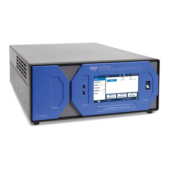
MODELS T703 and T703U
PHOTOMETRIC O
Copyright 2010-2016
Teledyne API
USER MANUAL
© TELEDYNE API (TAPI)
9970 CARROLL CANYON ROAD
SAN DIEGO, CALIFORNIA 92131-1106
USA
Toll-free Phone:
800-324-5190
Phone:
+1 858-657-9800
Fax:
+1 858-657-9816
Email:
api-sales@teledyne.com
Website:
http://www.teledyne-api.com/
CALIBRATOR
3
07223E DCN7334
03 August 2016
Advertisement
Table of Contents
Troubleshooting

Related Manuals for Teledyne T703


Summary of Contents for Teledyne T703
- Page 1 USER MANUAL MODELS T703 and T703U PHOTOMETRIC O CALIBRATOR © TELEDYNE API (TAPI) 9970 CARROLL CANYON ROAD SAN DIEGO, CALIFORNIA 92131-1106 Toll-free Phone: 800-324-5190 Phone: +1 858-657-9800 Fax: +1 858-657-9816 Email: api-sales@teledyne.com Website: http://www.teledyne-api.com/ Copyright 2010-2016 07223E DCN7334 Teledyne API...
- Page 3 NOTICE OF COPYRIGHT © 2010-2016 Teledyne API. All rights reserved. TRADEMARKS All trademarks, registered trademarks, brand names or product names appearing in this document are the property of their respective owners and are used herein for identification purposes only. 07223E DCN7334...
- Page 4 NEVER use a gas analyzer to sample any combustible gas(es)! Note Technical Assistance regarding the use and maintenance of this instrument or any other Teledyne API product can be obtained by contacting Teledyne API’s Technical Support Department: Telephone: 800-324-5190 Email: sda_techsupport@teledyne.com...
- Page 5 CONSIGNES DE SÉCURITÉ Des consignes de sécurité importantes sont fournies tout au long du présent manuel dans le but d’éviter des blessures corporelles ou d’endommager les instruments. Veuillez lire attentivement ces consignes. Chaque consigne de sécurité est représentée par un pictogramme d’alerte de sécurité; ces pictogrammes se retrouvent dans ce manuel et à...
- Page 6 PRODUCT RETURN All units or components returned to Teledyne API should be properly packed for handling and returned freight prepaid to the nearest designated Service Center. After the repair, the equipment will be returned, freight prepaid.
-
Page 7: About This Manual
(Revision History), how the content is organized (Organization), and the conventions used to present the information in this manual (Conventions Used). STRUCTURE This T703/T703U manual, PN 07223, is comprised of multiple documents, assembled in PDF format, as listed below. Part No. -
Page 8: Table Of Contents
4.5. Automatic Calibration Sequences ....................... 45 4.5.1. SETUP > SEQ: Programming Calibration Sequences ................46 4.5.1.1. Activating a Sequence from the T703/T703U Front Panel ............47 4.5.1.2. Naming a Sequence ........................48 4.5.1.3. Setting the Repeat Count for a Sequence ..................49 4.5.1.4. - Page 9 4.5.1.5. Setting Up Control Inputs for a Sequence ..................53 4.5.1.6. Setting Up Control Outputs for a Sequence .................. 54 4.5.1.7. Setting the Progress Reporting Mode for the Sequences ............. 55 4.5.2. Adding Sequence Steps ........................56 4.5.2.1. The GENERATE Step ........................57 4.5.2.2.
- Page 10 5.3. Multidrop RS-232 Set Up........................... 106 5.4. RS-485 Configuration of COM2......................... 108 5.5. Remote Access via the USB Port (Option) ....................108 5.6. Remote Access via the Ethernet ....................... 110 5.6.1. Configuring the Ethernet Interface using DHCP ................. 111 5.6.1.1. Manually Configuring the Network IP Addresses ................
- Page 11 Checking Measure / Reference Valve ....................174 8.6. Trouble Shooting the O Generator ......................174 8.6.1. Troubleshooting the O Generator in the T703 ................... 175 8.6.2. Troubleshooting the O Generator in the T703U ................175 8.7. Repair Procedures ............................. 176 8.7.1.
- Page 12 9.2.4.2. Sensor Inputs ..........................187 9.2.4.3. Thermistor Interface ........................187 9.2.4.4. Analog Outputs ..........................187 9.2.4.5. External Digital I/O ........................188 9.2.4.6. C Data Bus ..........................188 9.2.4.7. Power-up Circuit........................... 188 9.2.5. Power Supply and Circuit Breaker ...................... 188 9.2.6. AC Power Configuration ........................
- Page 13 Pressure Calibration Monitor Point – T703 ..................131 Figure 6-4: Pressure Calibration Monitor Points – T703U ................. 132 Figure 6-5: Pressure Regulator Monitor Connection Point (T703 and T703U) ..........132 Figure 6-6: Regulator Pressure Monitor Point (T703U only) ................ 133 Figure 6-7: Output Flow Calibration Monitor Point –...
- Page 14 Analog Output Test Function - Nominal Values Voltage Outputs ........... 168 Table 8-10: Status Outputs Check ........................168 Table 8-11: T703 Control Input Pin Assignments and Corresponding Signal I/O Functions ......169 Table 8-12: Control Outputs Pin Assignments and Corresponding Signal I/O Functions Check ...... 169 Table 9-1: Relay Board Status LEDs........................
- Page 15 LIST OF APPENDICES APPENDIX A - SOFTWARE DOCUMENTATION APPENDIX B - SPARE PARTS LIST APPENDIX C - WARRANTY REPAIR QUESTIONNAIRE APPENDIX D – INTERCONNECT DIAGRAM xiii 07223E DCN7334...
- Page 16 This page intentionally left blank. 07223E DCN7334...
-
Page 17: Introduction
As many as 50 independent calibration sequences may be programmed into the T703/T703U, covering time periods of up to one year. The setup of sequences is simple and intuitive. These sequences may be actuated manually, automatically, or by a remote signal. The sequences may be uploaded remotely, including remote editing. -
Page 18: Options
Calibration as a Transfer Standard (6x6) The Model T703 can be used as a Primary Ozone Standard. For this application the performance of the T703 Photometric Calibrator is calibrated to Standard Reference Photometer (SRP) Calibrators ordered with this option are verified and validated in accordance with the procedures prescribed by the U.S. -
Page 19: Specifications And Approvals
8 opto-isolated digital status outputs 1 USB com port Optional I/O 1 RS485 Multidrop RS232 Table 2-2: T703/T703U Specifications for Ozone Generator T703 T703U Flow Rate 1 to 5 LPM adjustable w/internal zero air source: 1 to 5 LPM adjustable... -
Page 20: Approvals And Certifications
Flow Rate +/- 10% 800 cc/min 2.2. APPROVALS AND CERTIFICATIONS The Teledyne API Models T703 and T703U Photometric O Calibrators were tested and certified for Safety and Electromagnetic Compatibility (EMC). This section presents the compliance statements for those requirements and directives. -
Page 21: Getting Started
GETTING STARTED 3.1. UNPACKING AND INITIAL SETUP CAUTION The T703 weighs about 16.1 kg (35.5 pounds) without options installed. To avoid personal injury, we recommend USING two persons to lift and carry the calibrator. CAUTION – Avoid Warranty Invalidation Printed circuit assemblies (PCAs) are sensitive to electro-static discharges too small to be felt by the human nervous system. -
Page 22: Front, Rear, And Internal Calibrator Description
Getting Started Teledyne API T703/T703U Calibrator Operation Manual • Remove the 2 screws fastening the top cover to the unit (one per side towards the rear). • Slide the cover backwards until it clears the calibrator’s front bezel. • Lift the cover straight up. -
Page 23: Figure 3-2: Display Screen And Touch Control
Teledyne API T703/T703U Calibrator Operation Manual Getting Started Figure 3-2: Display Screen and Touch Control The front panel liquid crystal display (LCD) screen includes touch control. Upon calibrator start-up, the LCD shows a splash screen and other initialization indicators before the main display appears. -
Page 24: Figure 3-3: Display/Touch Control Screen Mapped To Menu Charts
Getting Started Teledyne API T703/T703U Calibrator Operation Manual Figure 3-3: Display/Touch Control Screen Mapped to Menu Charts 07223E DCN7334... -
Page 25: Figure 3-4: Rear Panel Layout
Teledyne API T703/T703U Calibrator Operation Manual Getting Started Figure 3-4: Rear Panel Layout Table 3-2. Rear Panel Description Component Function Fan For cooling: pulls ambient air through chassis from side vents; exhausts through rear. Connector for three-prong cord to apply AC power to the instrument AC Power CAUTION! The cord’s power specifications (specs) MUST comply with the... -
Page 26: Figure 3-5: T703 Internal Layout - Top View
Getting Started Teledyne API T703/T703U Calibrator Operation Manual Figure 3-5: T703 Internal Layout – Top View 07223E DCN7334... -
Page 27: Figure 3-6: T703 Pneumatic Diagram
Teledyne API T703/T703U Calibrator Operation Manual Getting Started Figure 3-6: T703 Pneumatic Diagram 07223E DCN7334... -
Page 28: Figure 3-7: T703U Internal Layout - Top View
Getting Started Teledyne API T703/T703U Calibrator Operation Manual Pressure Figure 3-7: T703U Internal Layout - Top View 07223E DCN7334... -
Page 29: Figure 3-8: T703U Pneumatic Diagram
Teledyne API T703/T703U Calibrator Operation Manual Getting Started Figure 3-8: T703U Pneumatic Diagram 07223E DCN7334... -
Page 30: Electrical Connections
3.2.2. ANALOG OUTPUT TEST CHANNEL CONNECTIONS The T703 is equipped with an analog output channel accessible through a connector on the back panel of the instrument. The standard configuration for this output is 0-5 VDC. It can be set by the user to output one of a variety of diagnostic test functions (see Section 4.9.) -
Page 31: Connecting The Status Outputs
Teledyne API T703/T703U Calibrator Operation Manual Getting Started 3.2.3. CONNECTING THE STATUS OUTPUTS The status outputs report calibrator conditions via optically isolated NPN transistors, which sink up to 50 mA of DC current. These outputs can be used interface with devices that accept logic-level digital inputs, such as programmable logic controllers (PLCs). -
Page 32: Connecting The Control Inputs
Getting Started Teledyne API T703/T703U Calibrator Operation Manual 3.2.4. CONNECTING THE CONTROL INPUTS The calibrator is equipped with 12 digital control inputs that can be used to Initiate various user programmable calibration sequences (see Section 4.5.1.5 for instructions on assigning the control inputs to specific calibration sequences). -
Page 33: Figure 3-11: Digital Control Input Connectors
Teledyne API T703/T703U Calibrator Operation Manual Getting Started There are two methods for energizing the control inputs. The internal +5V available from the pin labeled “+” is the most convenient method. However, if full isolation is required, an external 5 VDC power supply should be used. -
Page 34: Connecting The Control Outputs
Getting Started Teledyne API T703/T703U Calibrator Operation Manual 3.2.5. CONNECTING THE CONTROL OUTPUTS The calibrator is equipped with 12 opto-isolated, digital control outputs. These outputs are activated by the user-programmable, calibration sequences (see Section 4.5.1.6 for instructions on assigning the control outputs to specific... -
Page 35: Communication Connections
Section 5.1.1 of this manual for instructions on configuration and usage. For RS- 485 communication, contact the factory. 3.2.6.4. Multidrop Network Connection If your unit has a Teledyne API RS-232 multidrop card (Option 62), see Section 5.3 for instructions on setting it up. 07223E DCN7334... -
Page 36: Pnenumatic Connections
20 °C or less. The pressure of the zero air should be regulated to 20-35 psig. NOTE When connecting an external source of zero air to an T703 with an internal zero air pump installed, the zero air pump should be disabled. -
Page 37: Output Manifold
3.3.3. OUTPUT MANIFOLD A four-port output manifold is supplied on the rear panel of the T703/T703U enabling simultaneous testing of up to two external instruments. Sample lines for ozone instruments to be calibrated can be connected directly to this manifold. -
Page 38: Warning Messages
Getting Started Teledyne API T703/T703U Calibrator Operation Manual 3.4.3. WARNING MESSAGES Because internal temperatures and other conditions may be outside be specified limits during the calibrator’s warm-up period, the software will suppress most warning conditions for 30 minutes after power up. If warning messages persist after the 30 minutes warm up period is over, investigate their cause using the troubleshooting guidelines in Section 8 of this manual. -
Page 39: Table 3-6: Possible Warning Messages At Start-Up
Teledyne API T703/T703U Calibrator Operation Manual Getting Started Table 3-6: Possible Warning Messages at Start-Up MESSAGE MEANING The calibrator’s A/D converter or at least one D/A ANALOG CAL WARNING channel has not been calibrated. Stored Configuration information has been reset to the CONFIG INITIALIZED factory settings or has been erased. -
Page 40: Functional Check
Getting Started Teledyne API T703/T703U Calibrator Operation Manual 3.4.4. FUNCTIONAL CHECK 1. After the calibrator’s components have warmed up for at least 30 minutes, verify that the software properly supports any hardware options that are installed. 2. Check to make sure that the calibrator is functioning within allowable operating parameters. -
Page 41: Operating Modes For The O
THIS IS THE DEFAULT AND MOST COMMON MODE OF OPERATION. This setting will be the default mode of the T703 calibrator and will be mused whenever the calibrator is using the GENERATE > AUTO command or the GENERATE sequence step to create a calibration mixture. When either the GENERATE >... -
Page 42: Setting The Output Flow Rate
Calculating Output Flow Rate First, add the sum of the flow requirements of all of the instruments to which the T703/T703U will be supplying calibration gas plus 1 LPM excess flow. For example, if the T703 is expected to supply calibration gas mixtures simultaneously to two analyzers, each requiring 0.8 LPM , the minimum Total... -
Page 43: Operating The Calibrator
OPERATING THE CALIBRATOR The T703/T703U calibrator is a computer-controlled calibrator with a dynamic menu interface for easy, yet powerful and flexible operation. All major operations are controlled from the front panel touch screen control. To assist in navigating the system’s software, a series of menu trees can be found in Appendix A of this manual. -
Page 44: Test Functions
Operating the Calibrator Teledyne API T703/T703U Calibrator Operation Manual 4.1. TEST FUNCTIONS A variety of TEST FUNCTIONS are available for viewing at the front panel whenever the calibrator is at the MAIN MENU. These measurements provide information about the present operating status of the calibrator and are useful during troubleshooting (see Section 8). -
Page 45: Overview Of Operating Modes
Operating the Calibrator 4.2. OVERVIEW OF OPERATING MODES The T703 calibrator software has a variety of operating modes. Most commonly, the calibrator will be operating in STANDBY mode. In this mode, the calibrator and all of its subsystems are inactive although TEST functions and WARNING messages are still updated and can be examined via the front panel display. -
Page 46: Standby Mode
(e.g. ANALOG OUTPUT STEP TEST) automatically place the calibrator into STANDBY mode when activated NOTE The T703/T703U calibrator should always be placed in STANDBY mode when not needed to produce calibration gas. STBY This can be done manually by pressing the button that appears when the calibrator’s... -
Page 47: General Information About The Generate Mode
Operating the Calibrator 4.4. GENERAL INFORMATION ABOUT THE GENERATE MODE The GENERATE mode is the mode of operation where the T703/T703U is actively producing calibration gas, either zero or some specified concentration of ozone. In the GENERATE mode the Zero Air Pump (if enabled) and Photometer Pump are turned on. -
Page 48: Setup > Seq: Programming Calibration Sequences
Operating the Calibrator Teledyne API T703/T703U Calibrator Operation Manual 4.5.1. SETUP > SEQ: PROGRAMMING CALIBRATION SEQUENCES A sequence is a database of single or multiple steps where each single step is an instruction that causes the instrument to perform an operation. These steps are grouped under a user-defined SEQUENCE NAME. -
Page 49: Activating A Sequence From The T703/T703U Front Panel
Teledyne API T703/T703U Calibrator Operation Manual Operating the Calibrator 4.5.1.1. Activating a Sequence from the T703/T703U Front Panel To activate an already programmed sequence from the front panel, press: STANDBY ACT =STANDBY Make sure that the calibrator is in <TST TST>... -
Page 50: Naming A Sequence
Operating the Calibrator Teledyne API T703/T703U Calibrator Operation Manual 4.5.1.2. Naming a Sequence The first step of creating a calibration sequence is to assign it a name. The name can be up to 10 characters and can be comprised of any alpha character (A to Z), and numeral (0 to 9) or the underscore character (“_“). -
Page 51: Setting The Repeat Count For A Sequence
Teledyne API T703/T703U Calibrator Operation Manual Operating the Calibrator 4.5.1.3. Setting the Repeat Count for a Sequence The sequence can be set to repeat a certain number of times, from 1 to 100. It can also be set to repeat indefinitely by inputting a zero (0) into the REPEAT COUNTER. -
Page 52: Using The Internal Clock To Trigger Sequences
Operating the Calibrator Teledyne API T703/T703U Calibrator Operation Manual 4.5.1.4. Using the Internal Clock to Trigger Sequences Sequences can be set to trigger based on the internal clock. The sequence can be set up to start at a predetermined date and time. It can also be set to repeat after a predetermined delay time. - Page 53 Teledyne API T703/T703U Calibrator Operation Manual Operating the Calibrator To specify a starting time for the sequence, press: STANDBY ACT =STANDBY Make sure that the calibrator is in standby <TST TST> GEN STBY SEQ SETUP mode. SETUP X.X PRIMARY SETUP MENU...
- Page 54 Operating the Calibrator Teledyne API T703/T703U Calibrator Operation Manual To set the delta timer, press: STANDBY ACT =STANDBY Make sure that the calibrator is in standby <TST TST> GEN STBY SEQ SETUP mode. SETUP X.X PRIMARY SETUP MENU CLK PASS...
-
Page 55: Setting Up Control Inputs For A Sequence
Teledyne API T703/T703U Calibrator Operation Manual Operating the Calibrator 4.5.1.5. Setting Up Control Inputs for a Sequence The calibrator’s control inputs allow the entire sequence to be triggered from an external source. This feature allows the calibrator to operate in a slave mode so that external control sources, such as a data logger can initiate the calibration sequences. -
Page 56: Setting Up Control Outputs For A Sequence
Operating the Calibrator Teledyne API T703/T703U Calibrator Operation Manual 4.5.1.6. Setting Up Control Outputs for a Sequence The calibrator’s control outputs allow the entire sequence to be triggered from an external source. This feature allows the calibrator to control devices that accept logic-level digital inputs, such as programmable logic controllers (PLCs), dataloggers, or digital relays/valve drivers. -
Page 57: Setting The Progress Reporting Mode For The Sequences
Teledyne API T703/T703U Calibrator Operation Manual Operating the Calibrator 4.5.1.7. Setting the Progress Reporting Mode for the Sequences As sequences run, the calibrator reports progress by displaying a message in the MODE field of the front panel display (See Figure 3-1). There are several types... -
Page 58: Adding Sequence Steps
Operating the Calibrator Teledyne API T703/T703U Calibrator Operation Manual 4.5.2. ADDING SEQUENCE STEPS To insert an instruction step into a sequence, navigate to the INSERT STEP submenu by pressing: STANDBY ACT =STANDBY Make sure that the calibrator is in standby <TST... -
Page 59: The Generate Step
The GENERATE Step This step operates and is programmed similarly to the GENERATE > AUTO. At the end of the programming sequence, the T703/T703U firmware will automatically insert a DURATION step that needs to be defined. To insert a GENERATE step into a sequence, press:... -
Page 60: The Standby Step
EXIT 4.5.2.3. The DURATION Step The duration step causes the T703/T703U to continue performing whatever action was called for by the preceding step of the sequence. • If that step put the instrument into STANDBY mode, the calibrator stays in STANDBY mode for the period specified by the DURATION step, •... -
Page 61: The Execseq Step
Teledyne API T703/T703U Calibrator Operation Manual Operating the Calibrator 4.5.2.4. The EXECSEQ Step The EXECSEQ step allows the sequence to call another, already programmed sequence. This is a very powerful tool in that it allows the user to create a “toolbox”... -
Page 62: The Cc Output Step
Operating the Calibrator Teledyne API T703/T703U Calibrator Operation Manual 4.5.2.5. The CC OUTPUT Step This instruction causes the sequence to set or reset the calibrator’s digital control outputs. It is very useful in situations where the control outputs are being used to trigger other devices that need to be turned off and on in synch with the operation of the calibrator as it progress through the sequence. -
Page 63: Deleting Or Editing An Individual Step In A Sequence
Teledyne API T703/T703U Calibrator Operation Manual Operating the Calibrator 4.5.2.6. Deleting or Editing an Individual Step in a Sequence To delete or edit an individual step in an existing Sequence, press: STANDBY ACT =STANDBY Make sure that the calibrator is in <TST... -
Page 64: Deleting A Sequence
Operating the Calibrator Teledyne API T703/T703U Calibrator Operation Manual 4.5.3. DELETING A SEQUENCE To delete a sequence from the calibrator’s memory, press: STANDBY ACT =STANDBY Make sure that the calibrator is in standby <TST TST> GEN STBY SEQ SETUP mode. -
Page 65: Setup > Cfg
Teledyne API T703/T703U Calibrator Operation Manual Operating the Calibrator 4.6. SETUP > CFG Pressing the CFG button displays the instrument’s configuration information. This display lists the calibrator model, serial number, firmware revision, software library revision, CPU type and other information. -
Page 66: Setup > Clk
4.7.1. SETTING THE INTERNAL CLOCK’S TIME AND DAY The T703/T703U has a time of day clock that supports the DURATION step of the calibration sequence feature, time of day TEST function, and time stamps on most COM port messages. To set the clock’s time and day, press:... -
Page 67: Adjusting The Internal Clock's Speed
Teledyne API T703/T703U Calibrator Operation Manual Operating the Calibrator 4.7.2. ADJUSTING THE INTERNAL CLOCK’S SPEED In order to compensate for CPU clocks which run faster or slower, you can adjust a variable called CLOCK_ADJ to speed up or slow down the clock by a fixed amount every day. -
Page 68: Setup > Pass
Operating the Calibrator Teledyne API T703/T703U Calibrator Operation Manual 4.8. SETUP > PASS The menu system provides password protection of the calibration and setup functions to prevent unauthorized adjustments. When the passwords have been enabled in the PASS menu item, the system will prompt the user for a password anytime a password-protected function (e.g., SETUP) is selected. - Page 69 Teledyne API T703/T703U Calibrator Operation Manual Operating the Calibrator Example: If all passwords are enabled, the following menu button sequence would be required to enter the VARS or DIAG submenus: STANDBY ACT =STANDBY <TST TST> GEN STBY SEQ SETUP SETUP X.X...
-
Page 70: Setup > Diag > Test Chan Output: Using The Test Channel Analog Output
Operating the Calibrator Teledyne API T703/T703U Calibrator Operation Manual 4.9. SETUP > DIAG > TEST CHAN OUTPUT: USING THE TEST CHANNEL ANALOG OUTPUT The calibrator comes equipped with one analog output. It can be set by the user to carry the current signal level of any one of the parameters listed in Table 4-8 and will output an analog VDC signal that rises and falls in relationship with the value of the parameter. - Page 71 Teledyne API T703/T703U Calibrator Operation Manual Operating the Calibrator To access the analog I/O configuration sub menu, press: STANDBY ACT =STANDBY Make sure that <TST TST> GEN STBY SEQ SETUP the calibrator is in standby mode. SETUP X.X PRIMARY SETUP MENU...
-
Page 72: Selecting A Test Channel Function To Output
Operating the Calibrator Teledyne API T703/T703U Calibrator Operation Manual 4.9.1.2. Selecting a TEST Channel Function to Output The Test Functions available to be reported are: Table 4-8: Test Channels Functions Available on the Analog Output TEST CHANNEL DESCRIPTION ZERO FULL SCALE... - Page 73 Teledyne API T703/T703U Calibrator Operation Manual Operating the Calibrator To activate the TEST Channel and select a function press: STANDBY ACT =STANDBY Make sure that the calibrator is <TST TST> GEN STBY SEQ SETUP in standby mode. SETUP X.X PRIMARY SETUP MENU...
-
Page 74: Test Channel Voltage Range Configuration
Operating the Calibrator Teledyne API T703/T703U Calibrator Operation Manual 4.9.1.3. TEST Channel Voltage Range Configuration In its standard configuration the analog outputs is set to output a 0 – 5 VDC signals. Several other output ranges are available (see Table 7-5). Each range has is usable from -5% to + 5% of the rated span. -
Page 75: Turning The Test Channel Over-Range Feature On/Off
Teledyne API T703/T703U Calibrator Operation Manual Operating the Calibrator 4.9.1.4. Turning the TEST Channel Over-Range Feature ON/OFF In its default configuration a ± 5% over-range is available on each of the TEST CHANNEL output. This over-range can be disabled if your recording device is sensitive to excess voltage or current. -
Page 76: Adding A Recorder Offset To The Test Channel
Operating the Calibrator Teledyne API T703/T703U Calibrator Operation Manual 4.9.1.5. Adding a Recorder Offset to the TEST Channel Some analog signal recorders require that the zero signal be significantly different from the baseline of the recorder in order to record slightly negative readings from noise around the zero point. -
Page 77: Test Channel Calibration
Teledyne API T703/T703U Calibrator Operation Manual Operating the Calibrator 4.9.2. TEST CHANNEL CALIBRATION TEST CHANNEL calibration needs to be carried out on first startup of the instrument (performed in the factory as part of the configuration process) or whenever re-calibration is required. -
Page 78: Enabling Or Disabling The Test Channel Auto-Cal Feature
Operating the Calibrator Teledyne API T703/T703U Calibrator Operation Manual 4.9.2.1. Enabling or Disabling the TEST CHANNEL Auto-Cal Feature To enable or disable the Auto-Cal feature for the TEST CHANNEL, press. From the AIO CONFIGURATION SUBMENU DIAG ANALOG I/O CONFIGURATION PREV NEXT... -
Page 79: Automatic Test Channel Calibration
Teledyne API T703/T703U Calibrator Operation Manual Operating the Calibrator 4.9.2.2. Automatic TEST Channel Calibration calibrate outputs group with AOUTS CALIBRATION command, press: NOTE Before performing this procedure, make sure that the AUTO CAL feature is turned OFF for CONC_OUT_1 and CONC_OUT_2, Make sure that the AUTO CAL feature is turned ON for the TEST CHANNEL (See Section 4.9.2.1) - Page 80 Operating the Calibrator Teledyne API T703/T703U Calibrator Operation Manual From the AIO CONFIGURATION SUBMENU DIAG ANALOG I/O CONFIGURATION PREV NEXT ENTR EXIT DIAG AIO AOUTS CALIBRATED: NO SET> EXIT Continue pressing SET> until you reach the output to be configured...
-
Page 81: Manual Calibration Of The Test Channel Configured For Voltage Ranges
Teledyne API T703/T703U Calibrator Operation Manual Operating the Calibrator 4.9.2.3. Manual Calibration of the TEST Channel Configured for Voltage Ranges For highest accuracy, the voltages of the analog outputs can be manually calibrated. NOTE: The menu for manually adjusting the analog output signal level will only appear if the AUTO-CAL feature is turned off for the channel being adjusted (see Section 4.9.2.1) - Page 82 Operating the Calibrator Teledyne API T703/T703U Calibrator Operation Manual To adjust the signal levels of an analog output channel manually, press: From the AIO CONFIGURATION SUBMENU DIAG ANALOG I/O CONFIGURATION PREV NEXT ENTR EXIT DIAG AIO AOUTS CALIBRATED: NO SET>...
-
Page 83: Ain Calibration
Teledyne API T703/T703U Calibrator Operation Manual Operating the Calibrator 4.9.3. AIN CALIBRATION This is the sub-menu to calibrate the instrument’s A-to-D conversion circuitry. This calibration should only be necessary after major repair such as a replacement of CPU, motherboard or power supplies. -
Page 84: Setup > More > Vars: Internal Variables (Vars)
Operating the Calibrator Teledyne API T703/T703U Calibrator Operation Manual 4.10. SETUP > MORE > VARS: INTERNAL VARIABLES (VARS) The T703/T703U has several user-adjustable software variables, which define certain operational parameters. The default values can be manually redefined using the VARS menu. - Page 85 Teledyne API T703/T703U Calibrator Operation Manual Operating the Calibrator To access and navigate the VARS menu, use the following menu button sequence: Make sure that the STANDBY ACT =STANDBY calibrator is in standby <TST TST> GEN STBY SEQ SETUP mode.
-
Page 86: Operating The Calibrator As An O
Operating the Calibrator Teledyne API T703/T703U Calibrator Operation Manual 4.11. OPERATING THE CALIBRATOR AS AN O PHOTOMETER The T703/T703U can easily be configured to measure an external source of ozone. 4.11.1. SET UP FOR OPERATION AS AN O PHOTOMETER To convert the T703/T703U from an O... - Page 87 Teledyne API T703/T703U Calibrator Operation Manual Operating the Calibrator To use the T703/T703U as a photometer, press: Make sure that the ACT test function is displayed in the message field Make sure that the STANDBY ACT =STANDBY calibrator is in STANDBY mode.
-
Page 88: Setup > Lvl: Setting Up And Using Leads (Dasibi) Operating Levels
4.12.1. GENERAL INFORMATION ABOUT LEADS LEVELS The T703 calibrator can be equipped with a version of firmware that includes support for LEADS, a data collection and analysis system specifically designed for handling meteorological and environmental data, particularly when there is a need to integrate data and control instrumentation from several different manufacturers. -
Page 89: Levels
Configuration for one or both of two status output blocks. Up to twenty levels can be defined and used with the T703 using a range of ID numbers from 0-98. Level 99 is reserved for standby. Are not time based and do not include characteristics such as start time or duration, therefore a single LEVEL can not switch between different concentration levels and flow rates. -
Page 90: Programming New Levels
Operating the Calibrator Teledyne API T703/T703U Calibrator Operation Manual 4.12.5. PROGRAMMING NEW LEVELS To begin programming a new LEVEL find the LVL submenu by pressing: Make sure that the STANDBY ACT =STANDBY calibrator is in standby <TST TST> GEN STBY SEQ SETUP mode. -
Page 91: Creating A Generate Level
Teledyne API T703/T703U Calibrator Operation Manual Operating the Calibrator 4.12.5.1. Creating a Generate LEVEL To create a LEVEL using the AUTO generation function, press: Starting at the CHOOSE ACTION Submenu CHOOSE ACTION Submenu SETUP X.X ACTION TO PERFORM:GENERATE PREV NEXT... -
Page 92: Editing Or Deleting A Level
Operating the Calibrator Teledyne API T703/T703U Calibrator Operation Manual 4.12.5.2. Editing or Deleting a LEVEL To edit or delete an existing LEVEL, press: STANDBY ACT =STANDBY Make sure that the calibrator is in standby mode. <TST TST> GEN STBY SEQ SETUP SETUP X.X... -
Page 93: Configuring Level Status Blocks
There are two STATUS BLOCKS associated with LEADS LEVELS. • BLOCK 1: This block corresponds to the physical CONTROL OUTPUT connections located on the back panel of the T703 (see Figure 3-4, Figure 3-12 and Section 3.2.5). • BLOCK 2: The second status block does not correspond to any physical... -
Page 94: Communications
Teledyne API T703/T703U Calibrator Operation Manual COMMUNICATIONS 5.1. USING THE ANALYSER’S COMMUNICATION PORTS The T703 is equipped with two serial communication ports, labeled RS232 (male DB-9 connector) and COM2 (female DB-9 connector), a USB com port and an Ethernet port located on the rear panel. -
Page 95: Serial Com Port Default Settings And Connector Pin Assignments
Teledyne API T703/T703U Calibrator Operation Manual Communications 5.1.2. SERIAL COM PORT DEFAULT SETTINGS AND CONNECTOR PIN ASSIGNMENTS Received from the factory, the calibrator is set up to emulate an RS-232 DCE device. • RS-232 (COM1): RS-232 (fixed), DB-9 male connector. -
Page 96: Figure 5-2: Cpu Com1 & Com2 Connector Pin-Outs For Rs-232 Mode
NOTE Cables that appear to be compatible because of matching connectors may incorporate internal wiring that makes the link inoperable. Check cables acquired from sources other than Teledyne API for pin assignments before using. To assist in properly connecting the serial ports to either a computer or a modem, there are activity indicators just above the RS-232 port. -
Page 97: Com Port Baud Rate
Teledyne API T703/T703U Calibrator Operation Manual Communications If both LEDs are still not illuminated, make sure the cable properly constructed. 5.1.3. COM PORT BAUD RATE To select the baud rate of either one of the COM Ports, press: STANDBY ACT =STANDBY <TST... -
Page 98: Table 5-1: Com Port Communication Modes
Modes are listed in the order in which they appear in the SETUP > MORE > COMM > COM[1 OR 2] > MODE menu The default setting for this feature is ON. Do not disable unless instructed to by Teledyne API’s Technical Support personnel. - Page 99 Teledyne API T703/T703U Calibrator Operation Manual Communications STANDBY ACT =STANDBY <TST TST> GEN STBY SEQ SETUP SETUP X.X PRIMARY SETUP MENU SEQ CFG CLK PASS MORE EXIT SETUP X.X SECONDARY SETUP MENU COMM VARS DIAG EXIT SETUP X.X COMMUNICATIONS MENU...
-
Page 100: Com Port Testing
Communications Teledyne API T703/T703U Calibrator Operation Manual 5.1.5. COM PORT TESTING The serial ports can be tested for correct connection and output in the COM menu. This test sends a string of 256 ‘w’ characters to the selected COM port. -
Page 101: Machine Id
Each model of Teledyne API instruments is initially configured with a default Machine ID code, which is editable; all T703 calibrators have a Machine ID of either 703 or 0. The Machine ID number is only important if more than one... -
Page 102: Terminal Operating Modes
Teledyne API T703/T703U Calibrator Operation Manual 5.1.7. TERMINAL OPERATING MODES The T703 can be remotely configured, calibrated or queried for stored data through the serial ports. As terminals and computers use different communication schemes, the calibrator supports two communicate modes specifically designed to interface with these two types of devices. -
Page 103: Command Syntax
<CR> is a carriage return. All commands must be terminated by a carriage return (usually achieved by pressing the ENTER key on a computer). Table 5-3: Teledyne API Serial I/O Command Types COMMAND COMMAND TYPE Calibration Diagnostic... -
Page 104: Data Types
Communications Teledyne API T703/T703U Calibrator Operation Manual 5.1.7.3. Data Types Data types consist of integers, hexadecimal integers, floating-point numbers, Boolean expressions and text strings. • Integer data are used to indicate integral quantities such as a number of records, a filter length, etc. They consist of an optional plus or minus sign, followed by one or more digits. -
Page 105: General Message Format
5.1.7.6. COM Port Password Security In order to provide security for remote access of the T703, a LOGON feature can be enabled to require a password before the instrument will accept commands. This is done by turning on the SECURITY MODE (Mode 4, Section 5.1.4). -
Page 106: Remote Access By Modem
• The DTE-DCE is in the DCE position. • The T703 COM port is set for a baud rate that is compatible with the modem, • The Modem is designed to operate with an 8-bit word length with one stop bit. - Page 107 Teledyne API T703/T703U Calibrator Operation Manual Communications To Initialize the modem press: STANDBY ACT =STANDBY <TST TST> GEN STBY SEQ SETUP SETUP X.X PRIMARY SETUP MENU SEQ CFG CLK PASS MORE EXIT SETUP X.X SECONDARY SETUP MENU COMM VARS DIAG EXIT SETUP X.X...
-
Page 108: Multidrop Rs-232 Set Up
Communications Teledyne API T703/T703U Calibrator Operation Manual 5.3. MULTIDROP RS-232 SET UP When the RS-232 Multidrop option is installed, connection adjustments and configuration through the menu system are required. This section provides instructions for the internal connection adjustments, then for external connections, and ends with instructions for menu-driven configuration. -
Page 109: Figure 5-3: Jumper And Cables For Multidrop Mode
Teledyne API T703/T703U Calibrator Operation Manual Communications Figure 5-3: Jumper and Cables for Multidrop Mode 4. Close the instrument. 5. Referring to Figure 5-4, use straight-through DB9 male-DB9 female cables to interconnect the host RS232 port to the first instrument’s RS232 port; then from the first instrument’s COM2 port to the second instrument’s RS232 port;... -
Page 110: Configuration Of Com2
NOTE: Teledyne API recommends setting up the first link, between the Host and the first instrument and testing it before setting up the rest of the chain. The (communication) Host instrument can address only one instrument at a time, each by its unique ID (see Step 7 above). - Page 111 Hardware → Device Manager). This is the com port that should be set in the communications software, such as APIcom or Hyperterminal. Refer to the Quick Start (Direct Cable Connection) section of the Teledyne APIcom Manual, PN 07463. 07223E DCN7334...
-
Page 112: Remote Access Via The Ethernet
Communications Teledyne API T703/T703U Calibrator Operation Manual 5. In the instrument’s SETUP>MORE>COMM>COM2 menu, make the following settings: Baud Rate: 115200 COM2 Mode Settings: Quiet Mode Computer Mode MODBUS RTU MODBUS ASCII E,8,1 MODE E,7,1 MODE RS-485 MODE SECURITY MODE MULTIDROP MODE... -
Page 113: Configuring The Ethernet Interface Using Dhcp
5.6.1. CONFIGURING THE ETHERNET INTERFACE USING DHCP The Ethernet feature for your T703 uses Dynamic Host Configuration Protocol (DHCP) to configure its interface with your LAN automatically. This requires your network servers also be running DHCP. The calibrator will do this the first time you turn the instrument on after it has been physically connected to your network. - Page 114 Communications Teledyne API T703/T703U Calibrator Operation Manual To view the above properties listed in Table 7-5, press: STANDBY ACT =STANDBY <TST TST> GEN STBY SEQ SETUP SETUP X.X PRIMARY SETUP MENU SEQ CFG CLK PASS MORE EXIT SETUP X.X SECONDARY SETUP MENU...
-
Page 115: Manually Configuring The Network Ip Addresses
Teledyne API T703/T703U Calibrator Operation Manual Communications 5.6.1.1. Manually Configuring the Network IP Addresses Here are several circumstances when you may need to manually set the Ethernet configuration: • Your LAN is not running a DHCP software package, • The DHCP software is unable to initialize the calibrator’s interface;... - Page 116 Communications Teledyne API T703/T703U Calibrator Operation Manual STEP 2: Configure the INSTRUMENT IP, GATEWAY IP and SUBNET MASK addresses by pressing: Internet Configuration Touchscreen Button Functions From Step 1 above) BUTTON FUNCTION Press to cycle through the range of numerals and available characters (“0 –...
-
Page 117: Changing The Calibrator's Hostname
The HOSTNAME is the name by which the calibrator appears on your network. The default name for all Teledyne API T703 calibrators is T703. To change this name (particularly if you have more than one T703 calibrator on your network), press. -
Page 118: Apicom Remote Control Program
Ethernet. Running APICOM, a user can: • Establish a link from a remote location to the T703 through direct cable connection via RS-232 modem or Ethernet. • View the instrument’s front panel and remotely access all functions that could be accessed when standing in front of the instrument. -
Page 119: Calibration And Verification
The verification procedure can be performed using the instruments internal O generator (see Figure 6-1) or an external source of O (see Figure 6-2). In either case, an external source of zero air (such as a Teledyne API’s Model 701 Zero Air Generator) is required. 6.1.1. -
Page 120: Generator
Calibration and Verification Teledyne API T703/T703U Calibrator Operation Manual PHOTOMETER INLET PHOTOMETER OUTLET PHOTOMETER ZERO IN PHOTOMETER ZERO OUT EXHAUST line: Max Length=3 meters ( or 10 feet) EXHAUST ZERO AIR IN VENT DRY AIR IN Use 3/8" O.D. tubing for VENT line... -
Page 121: Calibration Manifold Exhaust/Vent Line
Teledyne API T703/T703U Calibrator Operation Manual Calibration and Verification External Zero Air External O Source Source REFERENCE PHOTOMETER To other calibrators or instruments Vent line Max Length=3 meters PHOTOMETER INLET ( or 10 feet) PHOTOMETER OUTLET Capped Vent line PHOTOMETER ZERO IN... -
Page 122: Verifying O 3 Photometer Performance
Calibration and Verification Teledyne API T703/T703U Calibrator Operation Manual 6.1.2. VERIFYING O PHOTOMETER PERFORMANCE To verify the performance of the internal photometer perform the following steps: STANDBY ACT=STANDBY Make sure that the calibrator is in <TST TST> STBY SEQ SETUP... -
Page 123: Photometer Zero Calibration
Teledyne API T703/T703U Calibrator Operation Manual Calibration and Verification 6.1.3.1. Photometer Zero Calibration To set the zero point offset for the T703 Photometric Calibrator’s photometer, press: STANDBY ACT =STANDBY <TST TST> GEN STBY SEQ SETUP SETUP X.X PRIMARY SETUP MENU... -
Page 124: Photometer Span Calibration
Calibration and Verification Teledyne API T703/T703U Calibrator Operation Manual 6.1.3.2. Photometer Span Calibration To set the response SLOPE for the T703 Photometric Calibrator’s photometer, press: STANDBY ACT =STANDBY <TST TST> GEN STBY SEQ SETUP SETUP X.X PRIMARY SETUP MENU CLK PASS... -
Page 125: O 3 Photometer Dark Calibration
Teledyne API T703/T703U Calibrator Operation Manual Calibration and Verification 6.1.4. PHOTOMETER DARK CALIBRATION The Dark Calibration Test turns off the Photometer UV Lamp and records any offset signal level of the UV Detector-Preamp-Voltage to Frequency Converter circuitry. This allows the instrument to compensate for any voltage levels... -
Page 126: O 3 Photometer Backpressure Compensation Calibration
EXIT 6.2. CALIBRATING THE O GENERATOR The T703/T703U calibrator’s software includes a routine for automatically calibrating the O generator. A calibration table of drive voltages stored in the calibrator’s memory is the basis for this calibration. This table is used by the T703/T703U to set initial O generator drive settings. -
Page 127: O 3 Generator Calibration Table
The instrument software will interpolate between two values in the table when an intermediate concentration is requested. For each point included in the table used by the T703/T703U to calibrate the O generator the user can set a drive voltage and a dwell time for that point. Each point can also be individually turned off or on. -
Page 128: Viewing Ogenerator Calibration Points
Calibration and Verification Teledyne API T703/T703U Calibrator Operation Manual 6.2.2. VIEWING O GENERATOR CALIBRATION POINTS To view these calibration points, press: STANDBY ACT =STANDBY Make sure that the calibrator is in standby <TST TST> GEN STBY SEQ SETUP mode. SETUP X.X... -
Page 129: Adding Or Editing O
Teledyne API T703/T703U Calibrator Operation Manual Calibration and Verification 6.2.3. ADDING OR EDITING O GENERATOR CALIBRATION POINTS To add a calibration point to the table or edit an existing point, press: Make sure that the STANDBY ACT =STANDBY calibrator is in standby <TST... -
Page 130: Deleting O Generator Calibration Points
Calibration and Verification Teledyne API T703/T703U Calibrator Operation Manual 6.2.4. DELETING O GENERATOR CALIBRATION POINTS To delete an existing calibration point, press: STANDBY ACT =STANDBY Make sure that the calibrator is in standby <TST TST> GEN STBY SEQ SETUP mode. -
Page 131: Turning O Generator Calibration Points On / Off
Teledyne API T703/T703U Calibrator Operation Manual Calibration and Verification 6.2.5. TURNING O GENERATOR CALIBRATION POINTS ON / OFF To enable or disable an existing calibration point, press: Make sure that the STANDBY ACT =STANDBY calibrator is in standby <TST TST>... -
Page 132: Performing An Automatic Calibration Of The Ogenerator
Calibration and Verification Teledyne API T703/T703U Calibrator Operation Manual 6.2.6. PERFORMING AN AUTOMATIC CALIBRATION OF THE O GENERATOR To run the automatic O generator calibration program, press: STANDBY ACT =STANDBY Make sure that the calibrator is in standby <TST TST>... -
Page 133: Calibrating Gas Pressure Sensors
Calibration and Verification 6.3. CALIBRATING GAS PRESSURE SENSORS The T703 Calibrator has two sensors that monitor the pressure of the gases flowing through the instrument: a Regulator pressure sensor and a Photometer Sample Gas pressure sensor. The T703U also has those two sensors plus one more: an O Generator Regulator pressure sensor. -
Page 134: Figure 6-4: Pressure Calibration Monitor Points - T703U
Calibration and Verification Teledyne API T703/T703U Calibrator Operation Manual Figure 6-4: Pressure Calibration Monitor Points – T703U Attach Pressure Monitor Here Pressure Regulator Figure 6-5: Pressure Regulator Monitor Connection Point (T703 and T703U) 07223E DCN7334... -
Page 135: Calibrating The Pressure Sensors
Teledyne API T703/T703U Calibrator Operation Manual Calibration and Verification Figure 6-6: Regulator Pressure Monitor Point (T703U only) 6.3.2. CALIBRATING THE PRESSURE SENSORS The following procedure requires a pump. If your unit does not have the internal pump option, temporarily connect an external pump. -
Page 136: Gas Flow Calibration
6.4. GAS FLOW CALIBRATION The T703/T703U has two gas flow characteristics that affect its performance: the flow of gas through the sample chamber of the instrument’s photometer and the total gas flow being output. While both are stored in the calibrator’s memory and... -
Page 137: Table 6-2: T703/T703U Gas Pressure To Output Flow Conversion Table
O gas input pressure sensor. The output-flow slope value is determined by performing an OUPUT FLOW calibration operation (see Section 6.4.2). Table 6-2: T703/T703U Gas Pressure to Output Flow conversion Table T703 REGULATOR PRESSURE TO OUTPUT FLOW PSIG 0.000 0.676... -
Page 138: Calibrating The Photometer's Sample Gas Flow
NOTE The procedure described in this section requires an independent, calibrated gas flow meter/monitor be connected to the EXHAUST fitting on the back of the T703/T703U. During the PHOTO FLOW calibration, the T703/T703U software automatically turns the DC pump downstream from the photometer ON. PHOTO FLOW calibration is followed by ACTUAL OUTPUT FLOW (output gas flow) calibration (Section 6.4.2). -
Page 139: Calibrating The Output Gas Flow
Output Gas Flow Set Up The procedure described in this section requires an independent, calibrated flow meter/monitor and the following set up: Figure 6-7: Output Flow Calibration Monitor Point – T703 Figure 6-8: Output Flow Calibration Monitor Point – T703U 07223E DCN7334... -
Page 140: Performing An Output Gas Flow Calibration
6.4.2.2. Performing an Output Gas Flow Calibration During the PHOTO FLOW calibration, the T703/T703U software automatically turns the DC pump downstream from the photometer OFF and the AC dry air pump ON. Once the PHOTO FLOW has been calibrated (Section 8.4.1 – menu sequence included here for continuity), the next step is to adjust the “ACTUAL... -
Page 141: Maintenance Schedule & Procedures
For the most part, the T703 calibrator is maintenance free, there are, however, a minimal number of simple procedures that when performed regularly will ensure that the T703 photometer continues to operate accurately and reliably over its the lifetime. - Page 142 Maintenance Schedule & Procedures Teledyne API T703/T703U Calibrator Operation Manual This page intentionally left blank. 07223E DCN7334...
-
Page 143: Table 7-1: T703 Maintenance Schedule
Maintenance Schedule & Procedures Teledyne API T703/T703U Calibrator Operation Manual Table 7-1: T703 Maintenance Schedule Date Performed Manual Item Action Freq Check Section Req’d. Weekly or after Verify Test Record and any Maintenance 3.4.4 Functions analyze or Repair Photometer No Replacement Required. Under Normal Circumstances the Pumps Will Last the Lifetime of the Instrument. - Page 144 Maintenance Schedule & Procedures Teledyne API T703/T703U Calibrator Operation Manual This page intentionally left blank. 07223E DCN7334...
-
Page 145: Performing Leak Checks
PRESSURE LEAK CHECK The following pressure leak check instructions can be used with either a leak checker (similar to the Teledyne API’s part number 01960, which contains a small pump, shut-off valve and pressure gauge) or a tank of pressurized gas, with the two-stage regulator adjusted to ≤... -
Page 146: Figure 7-1: T703 Pneumatic Setup For Performing Pressure Leak Checks
Maintenance Schedule & Procedures Teledyne API T703/T703U Calibrator Operation Manual Figure 7-1: T703 Pneumatic setup for performing Pressure Leak Checks Figure 7-2: T703U Pneumatic Setup for Performing Pressure Leak Checks 07223E DCN7334... -
Page 147: Cleaning Or Replacing The Absorption Tube
Teledyne API T703/T703U Calibrator Operation Manual Maintenance Schedule & Procedures 7.3. CLEANING OR REPLACING THE ABSORPTION TUBE NOTE: Although this procedure should never be needed as long as the user is careful only to supply the photometer with clean, dry and particulate free zero air, it is included here for those rare occasions when cleaning or replacing the absorption tube may be required. -
Page 148: Photometer Uv Source Lamp Adjustment
Maintenance Schedule & Procedures Teledyne API T703/T703U Calibrator Operation Manual 7.5. PHOTOMETER UV SOURCE LAMP ADJUSTMENT This procedure details the steps for adjustment of the UV source lamp in the optical bench assembly. This procedure should be done whenever the PHOTO REFERENCE test function value drops below 3000 mV. - Page 149 Teledyne API T703/T703U Calibrator Operation Manual Maintenance Schedule & Procedures Make sure that the STANDBY ACT =STANDBY instrument is in Standby <TST TST> GEN STBY SEQ SETUP mode. SETUP X.X PRIMARY SETUP MENU CLK PASS MORE EXIT SETUP X.X SECONDARY SETUP MENU...
-
Page 150: Photometer Uv Source Lamp Replacement
Maintenance Schedule & Procedures Teledyne API T703/T703U Calibrator Operation Manual Figure 7-3: Photometer – Location of UV Detector Gain Adjustment & UV Lamp Set Screw 7.6. PHOTOMETER UV SOURCE LAMP REPLACEMENT This procedure details the steps for replacement of the UV source lamp in the optical bench assembly. -
Page 151: Adjustment Or Replacement Of Ozone Generator Uv Lamp
Teledyne API T703/T703U Calibrator Operation Manual Maintenance Schedule & Procedures 12. Once a lamp position is found that corresponds to a maximum observed value for PHOTO_DET, tighten the lamp setscrew at the approximate maximum value observed. • If the value of PHOTO_DET is not within the range of 4400 – 4600 mV, adjust it accordingly. - Page 152 Maintenance Schedule & Procedures Teledyne API T703/T703U Calibrator Operation Manual This page intentionally left blank. 07223E DCN7334...
-
Page 153: General Troubleshooting & Service
• Use common sense when operating inside a running calibrator. 8.1. GENERAL TROUBLESHOOTING The T703 Photometric Calibrator has been designed so that problems can be rapidly detected, evaluated and repaired. During operation, it continuously performs diagnostic tests and provides the ability to evaluate its key operating parameters without disturbing monitoring operations. -
Page 154: Fault Diagnosis With Warning Messages
General Troubleshooting & Service Teledyne API T703/T703U Calibrator Operation Manual 5. Follow the procedures defined in Section 3.4.4 to confirm that the calibrator’s vital functions are working (power supplies, CPU, relay PCA, keyboard, PMT cooler, etc.). • See Figure 3-5 for general layout of components and sub-assemblies in the calibrator. - Page 155 Teledyne API T703/T703U Calibrator Operation Manual General Troubleshooting & Service Top: the CLR button is available to clear the warning message displayed in the Param field. Bottom: the MSG button indicates that at least one warning message has not yet been cleared The calibrator also alerts the user via the Serial I/O COM port(s) and causes the FAULT LED on the front panel to blink.
-
Page 156: Table 8-1: Front Panel Warning Messages
General Troubleshooting & Service Teledyne API T703/T703U Calibrator Operation Manual STANDBY SYSTEM RESET Suppresses the TEST GEN STBY SEQ MSG CLR SETUP warning messages STANDBY SYSTEM RESET MSG returns the active TEST GEN STBY SEQ CLR SETUP warnings to the message field. -
Page 157: Fault Diagnosis With Test Functions
Teledyne API T703/T703U Calibrator Operation Manual General Troubleshooting & Service WARNING FAULT CONDITION POSSIBLE CAUSES Possible failure of: Occurs when Ref is PHOTO REFERENCE - UV Lamp <2500 mVDC WARNING - UV Photo-Detector Preamp or >4950 mVDC. - THIS WARNING only appears on Serial I/O COM Port(s) -
Page 158: Using The Diagnostic Signal I/O Function
General Troubleshooting & Service Teledyne API T703/T703U Calibrator Operation Manual TEST FUNCTION DIAGNOSTIC RELEVANCE AND CAUSES OF FAULT CONDITIONS. - The there is sufficient open space to the side and rear of instrument to allow adequate ventilation. If the value displayed is too high the UV Source has become brighter. Adjust the variable gain potentiometer on the UV Preamp Board in the optical bench. -
Page 159: Figure 8-1: Example Of Signal I/O Function
Teledyne API T703/T703U Calibrator Operation Manual General Troubleshooting & Service • The technician can view the raw, unprocessed signal level of the calibrator’s critical inputs and outputs. • Many of the components and functions that are normally under algorithmic control of the CPU can be manually exercised. -
Page 160: Using The Analog Output Test Channel
General Troubleshooting & Service Teledyne API T703/T703U Calibrator Operation Manual 8.2. USING THE ANALOG OUTPUT TEST CHANNEL The signals available for output over the analog output channel can also be used as diagnostic tools. See Section 4.9 for instruction on activating the analog output and selecting a function. -
Page 161: Using The Internal Electronic Status Leds
Teledyne API T703/T703U Calibrator Operation Manual General Troubleshooting & Service 8.3. USING THE INTERNAL ELECTRONIC STATUS LEDS Several LEDs are located inside the instrument to assist in determining if the calibrators CPU, I C bus and Relay PCA are functioning properly. -
Page 162: Troubleshooting With Relay Board Status Leds
General Troubleshooting & Service Teledyne API T703/T703U Calibrator Operation Manual 8.3.2.2. Troubleshooting with Relay Board Status LEDs Figure 8-3: Relay PCA Status LEDs Used for Troubleshooting Table 8-5: Relay PCA Status LED Failure Indications INDICATES ACTIVATED BY DIAGNOSTIC TECHNIQUE Pump should start /stop. If not: •... -
Page 163: Subsystem Checkout
8.4.1. VERIFY SUBSYSTEM CALIBRATION A good first step when troubleshooting the operation of the T703 calibrator is to verify that its major subsystems are properly calibrated. These are: • Test Channel D > A conversion (see Section 4.9.2). -
Page 164: Figure 8-4: Location Of Dc Power Test Points On Relay Pca
General Troubleshooting & Service Teledyne API T703/T703U Calibrator Operation Manual DGND +5V AGND +15V -15V +12R 12V Figure 8-4: Location of DC Power Test Points on Relay PCA Table 8-6: DC Power Test Point and Wiring Color Codes NAME TEST POINT#... -
Page 165: I 2 C Bus
Teledyne API T703/T703U Calibrator Operation Manual General Troubleshooting & Service Agnd Agnd Dgnd -0.05 0.05 Chassis Dgnd Chassis -0.05 0.05 +12V Ret +12V 11.75 12.5 +12 V ret +12V Ret Dgnd -0.05 0.05 8.4.4. C BUS Operation of the I C bus can be verified by observing the behavior of D1 on the relay PCA &... -
Page 166: Photometer Ogenerator Pressure /Flow Sensor Assembly
The pressure/flow sensor PCA, located at the rear of the instrument between the O generator and the photometer pump (see Figure 3-5 for T703; see Figure 3-7 for T703U) can be checked with a Voltmeter. The following... - Page 167 Teledyne API T703/T703U Calibrator Operation Manual General Troubleshooting & Service PHOTOMETER PRESSURE SENSOR (ABSOLUTE PRESSURE): 1. Measure the pressure on the inlet side of S1 with an external pressure meter. 2. Measure the voltage across TP4 and TP1. • The expected value for this signal should be: Pressure ±...
-
Page 168: Motherboard
General Troubleshooting & Service Teledyne API T703/T703U Calibrator Operation Manual 8.4.9. MOTHERBOARD 8.4.9.1. A/D Functions The simplest method to check the operation of the A-to-D converter on the motherboard is to use the Signal I/O function under the DIAG menu to check the two A/D reference voltages and input signals that can be easily measured with a voltmeter. -
Page 169: Test Channel / Analog Outputs Voltage
Teledyne API T703/T703U Calibrator Operation Manual General Troubleshooting & Service 8.4.9.2. Test Channel / Analog Outputs Voltage To verify that the analog output is working properly, connect a voltmeter to the output in question and perform an analog output step test as follows:... -
Page 170: Status Outputs
General Troubleshooting & Service Teledyne API T703/T703U Calibrator Operation Manual Table 8-9: Analog Output Test Function - Nominal Values Voltage Outputs FULL SCALE OUTPUT OF VOLTAGE RANGE (see Section 4.9.1.3) 100mV STEP NOMINAL OUTPUT VOLTAGE 20 mV 40 mV 60 mV... -
Page 171: Control Inputs
Teledyne API T703/T703U Calibrator Operation Manual General Troubleshooting & Service 8.4.9.4. Control Inputs Table 8-11: T703 Control Input Pin Assignments and Corresponding Signal I/O Functions CONNECTOR INPUT CORRESPONDING I/O SIGNAL CONTROL_IN_1 CONTROL_IN_2 CONTROL_IN_3 CONTROL_IN_4 CONTROL_IN_5 CONTROL_IN_6 Bottom CONTROL_IN_7 Bottom CONTROL_IN_8... -
Page 172: Cpu
RS-232 COMMUNICATIONS 8.4.11.1. General RS-232 Troubleshooting Teledyne API calibrators use the RS-232 communications protocol to allow the instrument to be connected to a variety of computer-based equipment. RS-232 has been used for many years and as equipment has become more advanced, connections between various types of hardware have become increasingly difficult. -
Page 173: Troubleshooting Calibrator/Modem Or Terminal Operation
Check to make sure the set up command is correct (See Section 5.2) • Verify that the Ready to Send (RTS) signal is at logic high. The T703 sets pin 7 (RTS) to greater than 3 volts to enable modem transmission. -
Page 174: Uv Lamp Temperature
General Troubleshooting & Service Teledyne API T703/T703U Calibrator Operation Manual 8.4.12.3. UV Lamp Temperature There are three possible causes for the UV Lamp temperature to have failed. • The UV Lamp heater has failed. Check the resistance between pins 5 and 6 on the six-pin connector adjacent to the UV Lamp on the Optical Bench. -
Page 175: Slow Response To Changes In Concentration
Teledyne API T703/T703U Calibrator Operation Manual General Troubleshooting & Service Since many photometer behaviors that appear to be a dynamic in nature are often a symptom of a seemingly unrelated static problems, it is recommended that dynamic problems not be addressed until all static problems, warning conditions and subsystems have been checked and any problems found are resolved. -
Page 176: Cannot Zero
Zero-gas, then there is a "cross-port" leak in the m/r valve. 7. Press the final Zero button then press “NO” when asked, “ARE YOU SURE”. 8.6. TROUBLE SHOOTING THE O GENERATOR Troubleshooting the O generator differs between the T703 (Section 8.6.1) and the T703U (Section 8.6.2). 07223E DCN7334... -
Page 177: Troubleshooting The Ogenerator In The T703
8.6.2. TROUBLESHOOTING THE O GENERATOR IN THE T703U (See Section 8.6.1 for troubleshooting the T703 O generator). 1. Make sure the calibrator is idling in STANDBY mode. 2. Unplug the cable connector at P1 on the Lamp Power Supply and confirm that +15VDC is present between Pins 1 and 2 on the cable connector. -
Page 178: Repair Procedures
Spare Parts list in Appendix B for part numbers and kits): 1. Turn off power to the calibrator. 2. Locate the assembly to be repaired, see Figure 9-1 (T703) or Figure 9-2 (T703U). 3. Disconnect the pneumatic connection from the flow assembly. -
Page 179: Disk-On-Module Replacement Procedure
Teledyne API T703/T703U Calibrator Operation Manual General Troubleshooting & Service 8.7.2. DISK-ON-MODULE REPLACEMENT PROCEDURE NOTE Printed circuit assemblies (PCAs) are sensitive to electro-static discharges too small to be felt by the human nervous system. Failure to use ESD protection when working with electronic assemblies will void the instrument warranty. -
Page 180: Faq's
General Troubleshooting & Service Teledyne API T703/T703U Calibrator Operation Manual 8.8. FAQ’S The following list is from the TAPI Technical Support Department of the 10 most commonly asked questions relating to the Model T703 Photometric Calibrator. QUESTION ANSWER My ozone ACT =XXXX, why? Look at the Photo Ref/Meas readings from the photometer UV lamp detector are most likely too low and need to be adjusted. -
Page 181: Principles Of Operation
PRINCIPLES OF OPERATION 9.1. PNEUMATIC OPERATION 9.1.1. GAS FLOW CONTROL Gas flow rates are set by various flow control assemblies in the gas stream(s), locations indicated in Figure 9-1Figure 9-2. Figure 9-1. Location of Gas Flow Control Assemblies - T703 07223E DCN7334... -
Page 182: Photometer Critical Flow Orifice
9.1.2. INTERNAL GAS PRESSURE SENSORS There are two pressure sensors in the T703/T703U: one for the regulator and one for the photometer. See Figure 3-5 (T703) or Figure 3-7 (T703U) for the location of the Pressure/Flow Sensor. -
Page 183: Electronic Operation
Teledyne API T703/T703U Calibrator Operation Manual Principles of Operation range sensor. This data is used by the CPU when calculating the O concentration inside the absorption tube. This value is displayed on the front panel as a test measurement called PHOTO SPRESS. Note that this value is converted to units of Inches of Mercury (IN-HG-A) when displayed on the front panel. -
Page 184: Central Processing Unit (Cpu)
CPU and the calibrator’s other major components. Data are generated by the various sub components of the T703 (e.g. flow data from the MFCs, O concentration from the photometer). Analog signals are converted into digital data by a unipolar, analog-to-digital converter, located on the motherboard. -
Page 185: Disk On Module (Dom)
Disk On Module (DOM) The DOM is a 44-pin IDE flash chip with a storage capacity up to 256 MB. It is used to store the computer’s operating system, the Teledyne API firmware, and most of the operational data. 9.2.2.2. -
Page 186: Valve Control
Valve Control The relay board also hosts two valve driver IC's, each of which can drive up four valves. In the T703, the relay PCA controls only those valves associated with the generator and photometer. In the T703U, the relay PCA controls two additional valves: the Divert valve and the O Gen valve. -
Page 187: Heater Control
Teledyne API T703/T703U Calibrator Operation Manual Principles of Operation 9.2.3.2. Heater Control The relay PCA controls the DC heaters for the O generator and photometer lamp housing. MOTHER BOARD Converter Thermistor(s) (V/F) e.g. photometer sample gas temp.; photometer UV lamp temp.; O generator lamp temp.;... -
Page 188: Relay Pca Watchdog Indicator (D1)
Principles of Operation Teledyne API T703/T703U Calibrator Operation Manual Table 9-1: Relay Board Status LEDs COLOR DESCRIPTION FUNCTION/INDICATION Watchdog Circuit; I C bus Blinks when I C bus is operating properly operation. Yellow Zero Air Pump (option) Status When lit the zero air AC pump is running. -
Page 189: Motherboard
Teledyne API T703/T703U Calibrator Operation Manual Principles of Operation 9.2.4. MOTHERBOARD This is the largest electronic assembly in the calibrator and is mounted to the rear panel as the base for the CPU board and all I/O connectors. This printed circuit... -
Page 190: External Digital I/O
Principles of Operation Teledyne API T703/T703U Calibrator Operation Manual 9.2.4.5. External Digital I/O The external digital I/O performs two functions. The STATUS outputs carry logic-level (5V) signals through an optically isolated 8-pin connector on the rear panel of the calibrator. These outputs convey on/off information about certain calibrator conditions such as CONC VALID. - Page 191 Teledyne API T703/T703U Calibrator Operation Manual Principles of Operation SENSOR SUITES Sensor Control ANALOG SENSORS & I/O Logic AC POWER • O Generator Reference detector, DC POWER LOGIC DEVICES Pre-Amplifiers • Photometer UV & Amplifiers Detector (e.g. CPU, I C bus, Motherboard, etc.)
-
Page 192: Ac Power Configuration
Principles of Operation Teledyne API T703/T703U Calibrator Operation Manual SENSOR SUITES Sensor Control ANALOG SENSORS & I/O Logic AC POWER Photometer UV Detector DC POWER LOGIC DEVICES Pre-Amplifiers & Amplifiers (e.g. CPU, I C bus, Motherboard, etc.) POWER IN PS 1... -
Page 193: Ac Configuration - Internal Pump (Jp7)
Connects pump pin 1 to 220 / 240VAC power line 3 to 8 A jumper between pins 5 and 10 may be present on the jumper plug assembly, but is only functional on the T300 and has no function on the Models T700 or T703. 07223E DCN7334... -
Page 194: Front Panel Touchscreen/Display Interface
Pump AC Power Jumpers (JP7) 9.3. FRONT PANEL TOUCHSCREEN/DISPLAY INTERFACE The most commonly used method for communicating with the T703/T703U Dynamic Dilution Calibrator is via the instrument’s front panel LCD touchscreen display. The LCD display is controlled directly by the CPU board. The touchscreen is interfaced to the CPU by means of a touchscreen controller that connects to the CPU via the internal USB bus and emulates a computer mouse. -
Page 195: Front Panel Interface Pca
The calibrator’s core module is a high performance, Vortex 86SX-based microcomputer running Windows CE. Inside Windows CE, special software developed by Teledyne API interprets user commands from the various interfaces, performs procedures and tasks, stores data in the CPU’s various memory devices, and calculates the concentration of the gas being sampled. -
Page 196: Ogenerator Operation
Principles of Operation Teledyne API T703/T703U Calibrator Operation Manual Windows CE API FIRMWARE Calibrator Operations Memory Handling Calibration Procedures PC/104 BUS Configuration Procedures Calibration Data Autonomic Systems System Status Data Diagnostic Routines CALIBRATOR HARDWARE Interface Handling Sensor input Data Touchscreen... -
Page 197: Figure 9-13: O
Teledyne API T703/T703U Calibrator Operation Manual Principles of Operation Inlet from Diluent Source Valve To GPT Chamber + hv = 3O Valve Flow Control To O Assembly Exhaust Figure 9-13: Generator Internal Pneumatics 07223E DCN7334... -
Page 198: Generator Pneumatic Operation
Principles of Operation Teledyne API T703/T703U Calibrator Operation Manual 9.5.2. GENERATOR PNEUMATIC OPERATION The rate of flow through the O generator is controlled by a flow control assembly located on the Regulator Sub-Assembly in the front of the calibrator. Generator... - Page 199 Teledyne API T703/T703U Calibrator Operation Manual Principles of Operation Motherboard PC 104 Generator Input CPU Card Pressure Sensor PC 104 Bus Disk on Generator UV Lamp Module Temperature Generator Reference Lamp Detector C Bus Generator Lamp Supply RELAY PCA Status...
-
Page 200: O 3 Generator Temperature Control
Principles of Operation Teledyne API T703/T703U Calibrator Operation Manual 9.5.3.1. Generator Temperature Control In order to operate at peak efficiency the UV lamp of the O generator is maintained at a constant 48ºC. if the lamp temperature falls below 43ºC or rises above 53ºC a warning is issued by the CPU. - Page 201 In the case of the Model T703, Ozone (O α is the absorption coefficient that tells how well O absorbs light at the specific wavelength of interest.
-
Page 202: The Measurement / Reference Cycle
Principles of Operation Teledyne API T703/T703U Calibrator Operation Manual Τ inHg × × × α Κ Ρ In a nutshell the photometer: •... -
Page 203: Figure 9-18: T703 O
Teledyne API T703/T703U Calibrator Operation Manual Principles of Operation Figure 9-18: T703 O Photometer Gas Flow – Measure Cycle Figure 9-19: T703 O Photometer Gas Flow – Reference Cycle 07223E DCN7334... -
Page 204: The Absorption Path
Principles of Operation Teledyne API T703/T703U Calibrator Operation Manual Figure 9-20: T703U O3 Photometer Gas Flow – Measure Cycle Figure 9-21: T703U O Photometer Gas Flow – Reference Cycle 9.6.1.3. The Absorption Path In the most basic terms, the photometer uses a high energy, mercury vapor lamp to generate a beam of UV light. -
Page 205: Interferent Rejection
Teledyne API T703/T703U Calibrator Operation Manual Principles of Operation through the Absorption Tube. Therefore, no complex mirror system is needed to lengthen the effective path by bouncing the beam back and forth. Finally, the UV passes through a similar window at the other end of the absorption tube and is detected by a specially designed vacuum diode that only detects radiation at or very near a wavelength of 254nm. -
Page 206: Photometer Pneumatic Operation
Principles of Operation Teledyne API T703/T703U Calibrator Operation Manual • A thermistor and DC heater attached to the UV Lamp to maintain the Lamp at an optimum operating temperature. • 42 cm long quartz absorption tube. • A thermistor attached to the quartz tube for measuring sample gas temperature. -
Page 207: Photometer Electronic Operation
Teledyne API T703/T703U Calibrator Operation Manual Principles of Operation 9.6.4. PHOTOMETER ELECTRONIC OPERATION Motherboard PC 104 CPU Card Converter Disk on Module Photometer C Bus Sample Gas Thermistor Interface Pressure Sensor RELAY PCA Photometer M/R Valve Photometer (Located on O... -
Page 208: Pneumatic Sensors For The O Photometer
Principles of Operation Teledyne API T703/T703U Calibrator Operation Manual The following TEST functions report these temperatures and are viewable from the instrument’s front panel: • PHOTO LAMP TEMP - The temperature of the UV Lamp reported in ºC. • PHOTO STEMP - The temperature of the Sample gas in the absorption tube reported in ºC. - Page 209 (Mbps) 100BaseT same as 10BaseT except ten times faster (100 Mbps) APICOM name of a remote control program offered by Teledyne-API to its customers ASSY Assembly Code-Activated Switch Corona Discharge, a frequently luminous discharge, at the surface of a conductor or...
- Page 210 Glossary Teledyne API T703/T703U Calibrator Operation Manual Term Description/Definition Disk On Module, a 44-pin IDE flash drive with up to 128MB storage capacity for instrument’s firmware, configuration settings and data Disk Operating System DRAM Dynamic Random Access Memory DR-DOS Digital Research DOS...
- Page 211 Teledyne API T703/T703U Calibrator Operation Manual Glossary Term Description/Definition Programmable Logic Controller, a device that is used to control instruments based on a logic level signal coming from the instrument Programmable Logic Device Phase Lock Loop Photo Multiplier Tube, a vacuum tube of electrodes that multiply electrons collected and...
- Page 212 Glossary Teledyne API T703/T703U Calibrator Operation Manual This page intentionally left blank. 07223E DCN7334...
- Page 213 APPENDIX A – Software Documentation Teledyne API - Models T703, T703U, 703E MENU TREES (05745F DCN7107) APPENDIX A – Software Documentation APPENDIX A-1: SOFTWARE MENU TREES APPENDIX A-2: SERIAL I/O SETUP VARIABLES APPENDIX A-3: WARNINGS AND TEST FUNCTIONS APPENDIX A-4: SIGNAL I/O DEFINITIONS...
- Page 214 APPENDIX A – Software Documentation Teledyne API - Models T703, T703U, 703E MENU TREES (05745F DCN7107) 07223E DCN7334...
- Page 215 Teledyne API - Models T703, T703U, 703E MENU TREES (05745F DCN7107) APPENDIX A-1: Software Menu Trees APPENDIX A-1: Software Menu Trees MAIN MENU TEST STBY SETUP AUTO <TST TST> Press to PREV NEXT clear an Press to cause calibrator to...
- Page 216 APPENDIX A-1: Software Menu Trees Teledyne API - Models T703, T703U, 703E MENU TREES (05745F DCN7107) MAIN MENU SETUP PASS MORE See PRIMARY SETUP Menu See SECONDARY SEQUENCE Submenu SETUP Menu PREV NEXT TIME DATE MODE PHOT MODEL TYPE AND NUMBER ...
-
Page 217: Main Menu
Teledyne API - Models T703, T703U, 703E MENU TREES (05745F DCN7107) APPENDIX A-1: Software Menu Trees MAIN MENU SETUP EDIT PRNT EXIT PREV NEXT PRNT EXIT EDIT Inserts a new sequence Edits existing sequence Cycles through list of already programmed calibration sequences <SET... - Page 218 APPENDIX A-1: Software Menu Trees Teledyne API - Models T703, T703U, 703E MENU TREES (05745F DCN7107) SETUP MORE MAIN MENU DIAG VARS COMM ENTER PASSWORD: 818 INET COM1 COM2 PREV NEXT JUMP PRNT EDIT ENTER PASSWORD: 818 <SET SET> EDIT...
- Page 219 Teledyne API - Models T703, T703U, 703E MENU TREES (05745F DCN7107) APPENDIX A-1: Software Menu Trees SETUP MORE DIAG MAIN MENU ENTER PASSWORD: 818 PREV NEXT PHOTO FLOW ANALOG ANALOG I/O TEST CHAN O3 GEN PRESSURE SIGNAL I/O SENSOR OUTPUT...
- Page 220 APPENDIX A-1: Software Menu Trees Teledyne API - Models T703, T703U, 703E MENU TREES (05745F DCN7107) SETUP MORE DIAG MAIN MENU ENTER PASSWORD: 818 DIAG menu is inactive when instrument is in GENERATE mode. PREV NEXT O3 GEN FLOW PRESSURE...
- Page 221 Teledyne API - Models T703, T703U, 703E MENU TREES (05745F DCN7107) APPENDIX A-1: Software Menu Trees MAIN MENU SETUP PREV NEXT EDIT PRNT EXIT Inserts a new Level Edits existing Level Only appears when the Cycles through list of optional LEADS already programmed Levels software is installed.
- Page 222 APPENDIX A-1: Software Menu Trees Teledyne API - Models T703, T703U, 703E MENU TREES (05745F DCN7107) This page intentionally left blank. 07223E DCN7334 A-10...
-
Page 223: Figure 9-23: O
Teledyne API - Models T703, T703U, 703E MENU TREES (05745F DCN7107) APPENDIX A-2: Serial I/O Setup Variables APPENDIX A-2: Serial I/O Setup Variables Table A-1: Setup Variables Setup Variable Numeric Default Value Description Units Value Range PHOTO_LAMP ºC 0–100 Photometer lamp temperature set point and warning limits. - Page 224 APPENDIX A-3: Warnings and Test FunctionsTeledyne API - Models T703, T703U, 703E MENU TREES (05745F DCN7107) APPENDIX A-3: Warnings and Test Functions Table A-2: Warning Messages NAME MESSAGE TEXT DESCRIPTION WSYSRES Instrument was power-cycled or the CPU was reset. SYSTEM RESET WDATAINIT Data storage was erased.
- Page 225 Teledyne API - Models T703, T703U, 703E MENU TREES (05745F DCN7107)APPENDIX A-3: Warnings and Test Functions Table A-3: Test Functions TEST FUNCTION NAME MESSAGE TEXT DESCRIPTION ACT=GENERATE 37 PPB O3 Actual concentration being generated, computed from real- ACTCONC time inputs.
- Page 226 APPENDIX A-4: Signal I/O Definitions Teledyne API - Models T703, T703U, 703E MENU TREES (05745F DCN7107) APPENDIX A-4: Signal I/O Definitions Table A-4: Signal I/O Definitions MODELS T703, T703U, 703E I/O Signal List for Latest Revision Signal Name Bit or...
- Page 227 Teledyne API - Models T703, T703U, 703E MENU TREES (05745F DCN7107) APPENDIX A-4: Signal I/O Definitions MODELS T703, T703U, 703E I/O Signal List for Latest Revision Signal Name Bit or Description Channel Number 0 = pump on for zero air...
- Page 228 APPENDIX A-4: Signal I/O Definitions Teledyne API - Models T703, T703U, 703E MENU TREES (05745F DCN7107) MODELS T703, T703U, 703E I/O Signal List for Latest Revision Signal Name Bit or Description Channel Number Rear board temperature MUX analog inputs Internal box temperature...
- Page 229 Teledyne API - Models T703, T703U, 703E MENU TREES (05745F DCN7107)APPENDIX A-5: Terminal Command Designators APPENDIX A-5: Terminal Command Designators Table A-5: Terminal Command Designators COMMAND ADDITIONAL COMMAND SYNTAX DESCRIPTION ? [ID] Display help screen and commands list LOGON [ID]...
- Page 230 APPENDIX A-6: MODBUS Registers Teledyne API - Models T703, T703U, 703E MENU TREES (05745F DCN7107) APPENDIX A-6: MODBUS Registers MODBUS Description Units Register Address (dec., 0-based) MODBUS Floating Point Input Registers (32-bit IEEE 754 format; read in high-word, low-word order; read-only)
- Page 231 Teledyne API - Models T703, T703U, 703E MENU TREES (05745F DCN7107) APPENDIX A-6: MODBUS Registers MODBUS Description Units Register Address (dec., 0-based) MODBUS Coil Registers (single-bit; read/write) 00-99 Trigger execution of sequence whose name begins with ―00‖ - ―99‖. Turning a coil on executes a sequence.
- Page 232 APPENDIX A-6: MODBUS Registers Teledyne API - Models T703, T703U, 703E MENU TREES (05745F DCN7107) This page intentionally left blank. 07223E DCN7334 A-20...
- Page 233 APPENDIX B - Spare Parts Use of replacement parts other than those supplied by Teledyne Advanced Note Pollution Instrumentation (TAPI) may result in non-compliance with European standard EN 61010-1. Due to the dynamic nature of part numbers, please call the factory for more recent updates to part numbers: +1 858-657-9800 or toll free 800-324-5190.
- Page 234 T703 Spare Parts List (reference: 072240000B, DCN7174) Page 1 of 2 Part Nbr Part 000940100 CD, ORIFICE, .003 GREEN (KB) 006120100 ASSY,OZ.GEN LAMP (BIR) (OP5) 022710000 ABSORPTION TUBE, QUARTZ, (PA) 040010000 ASSY, FAN REAR PANEL (B/F) 040300110 ASSY, CONFIG PLUG, 100-115V...
- Page 235 T703 Spare Parts List (reference: 072240000B, DCN7174) Page 2 of 2 Part Nbr Part FM0000004 FLOWMETER (KB) FM0000005 FLOW RESTRICTOR, 5000-1/4-10000CCM NONE FM0000006 FLOW RESTRICTOR, 5000-1/4-5000CCM BLACK HW0000005 FOOT (VMI) HW0000020 SPRING (VMI) HW0000380 HANDLE, CARRYING, 9.25", BLK * HW0000453 SUPPORT, CIRCUIT BD, 3/16"...
- Page 236 PCA, LVDS TRANSMITTER BOARD 069500000 PCA, SERIAL & VIDEO INTERFACE BOARD 072150000 ASSY. TOUCHSCREEN CONTROL MODULE 072230000 MANUAL, OPERATORS, T703/T703U 072250100 DOM, w/SOFTWARE, STD, T703 * 083290100 ASSY, OPTICAL BENCH, W/ SCRUBBER FL0000001 FILTER, SS (PA) FL0000003 FILTER, DFU (PA) 07223E DCN7334...
- Page 237 T703U Spare Parts List (reference: 077470000B, DCN7174) Page 2 of 2 Part Nbr Part FL0000020 CARBON FILTER, DAU, 000 GRADE *(KB) FM0000004 FLOWMETER (KB) FM0000005 FLOW RESTRICTOR, 5000-1/4-10000CCM NONE FM0000006 FLOW RESTRICTOR, 5000-1/4-5000CCM BLACK FM0000007 REGULATOR, PRESSURE, BRASS COLLAR, 0-30PSI(PA) FT0000337 TEE, BRASS, 1/4"...
- Page 238 This page intentionally left blank. 07223E DCN7334...
- Page 239 Appendix C Warranty/Repair Questionnaire T703, T703U, 703E (05747E DCN7107) CUSTOMER: _______________________________ PHONE: _____________________________________ CONTACT NAME: ___________________________ FAX NO. _____________________________________ SITE ADDRESS: ____________________________________________________________________________ MODEL TYPE: _______________ SERIAL NO.: _________________ FIRMWARE REVISION: _____________ Are there any failure messages? ________________________________________________________________ __________________________________________________________________________________________ ___________________________________________________________________________________________ ___________________________________________________________________________________________...
- Page 240 What tests have you done trying to solve the problem? ______________________________________________ ___________________________________________________________________________________________ ___________________________________________________________________________________________ ___________________________________________________________________________________________ ___________________________________________________________________________________________ Thank you for providing this information. Your assistance enables Teledyne Instruments to respond faster to the problem that you are encountering. OTHER NOTES: _____________________________________________________________________________ ___________________________________________________________________________________________ ___________________________________________________________________________________________...
- Page 241 Appendix D - Interconnect Diagram 07223E DCN7334...
Need help?
Do you have a question about the T703 and is the answer not in the manual?
Questions and answers