Endress+Hauser Proline Promass A 100 PROFINET Operating Instructions Manual
Coriolis flowmeter
Hide thumbs
Also See for Proline Promass A 100 PROFINET:
- Operating instructions manual (56 pages) ,
- Operating instructions manual (118 pages) ,
- Operating instructions manual (160 pages)

Related Manuals for Endress+Hauser Proline Promass A 100 PROFINET


Summary of Contents for Endress+Hauser Proline Promass A 100 PROFINET
- Page 1 Products Solutions Services BA01424D/06/EN/02.24-00 71674485 2024-11-01 Valid as of version 01.00.zz (Device firmware) Operating Instructions Proline Promass A 100 PROFINET Coriolis flowmeter...
- Page 2 • The manufacturer reserves the right to modify technical data without prior notice. Your Endress+Hauser sales organization will supply you with current information and updates to this manual. Endress+Hauser...
- Page 3 Proline Promass A 100 PROFINET Table of contents Table of contents 6.2.3 Mounting the measuring device ..25 About this document ....6 6.2.4...
- Page 4 ....13.3 Endress+Hauser services ....123 10.8 Simulation ......78 10.9 Protecting settings from unauthorized access .
- Page 5 Proline Promass A 100 PROFINET Table of contents Technical data ....129 16.1 Application ......129 16.2 Function and system design .
- Page 6 About this document Proline Promass A 100 PROFINET About this document Document function These Operating Instructions contain all the information required in the various life cycle phases of the device: from product identification, incoming acceptance and storage, to installation, connection, operation and commissioning, through to troubleshooting, maintenance and disposal.
- Page 7 For an overview of the scope of the associated Technical Documentation, refer to the following: • Device Viewer (www.endress.com/deviceviewer): Enter the serial number from the nameplate • Endress+Hauser Operations app: Enter serial number from nameplate or scan matrix code on nameplate. Endress+Hauser...
- Page 8 About this document Proline Promass A 100 PROFINET The following documentation may be available depending on the device version ordered: Document type Purpose and content of the document Technical Information (TI) Planning aid for your device The document contains all the technical data on the device and provides an overview of the accessories and other products that can be ordered for the device.
- Page 9 Proline Promass A 100 PROFINET Safety instructions Safety instructions Requirements for the personnel The personnel for installation, commissioning, diagnostics and maintenance must fulfill the following requirements: ‣ Trained, qualified specialists must have a relevant qualification for this specific function and task.
- Page 10 Verification for borderline cases: ‣ For special fluids and fluids for cleaning, Endress+Hauser is glad to provide assistance in verifying the corrosion resistance of fluid-wetted materials, but does not accept any warranty or liability as minute changes in the temperature, concentration or level of contamination in the process can alter the corrosion resistance properties.
- Page 11 Proline Promass A 100 PROFINET Safety instructions IT security Our warranty is valid only if the product is installed and used as described in the Operating Instructions. The product is equipped with security mechanisms to protect it against any inadvertent changes to the settings.
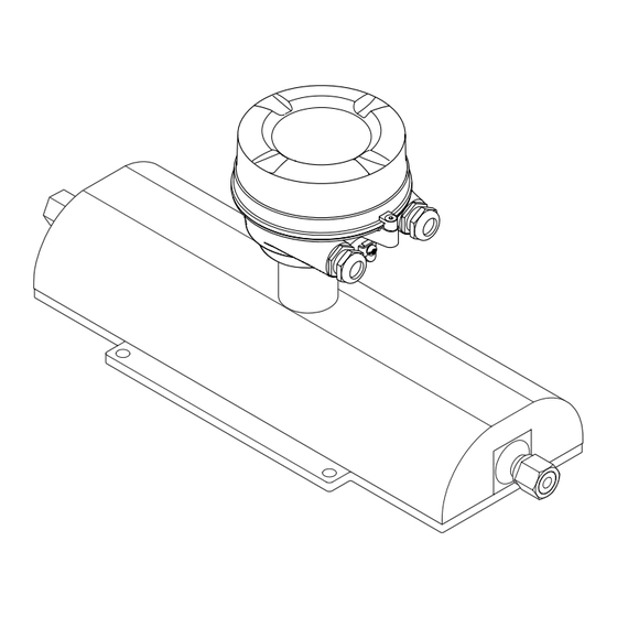
- Page 12 Product description Proline Promass A 100 PROFINET Product description The device consists of a transmitter and a sensor. The device is available as a compact version: The transmitter and sensor form a mechanical unit. Product design 3.1.1 Device version with PROFINET communication protocol A0023153 ...
- Page 13 • Enter the serial numbers from the nameplates in the Device Viewer (www.endress.com/deviceviewer): all the information about the device is displayed. • Enter the serial numbers from the nameplates into the Endress+Hauser Operations app or scan the DataMatrix code on the nameplate with the Endress+Hauser Operations app: all the information about the device is displayed.
- Page 14 Incoming acceptance and product identification Proline Promass A 100 PROFINET 4.2.1 Transmitter nameplate Order code: Ser. no.: Ext. ord. cd.: A0030222 2 Example of a transmitter nameplate Manufacturer address/certificate holder Name of the transmitter Order code Serial number Extended order code Electrical connection data, e.g.
- Page 15 Proline Promass A 100 PROFINET Incoming acceptance and product identification 4.2.2 Sensor nameplate Order code: Ser. no.: Ext. ord. cd.: Date: A0029199 3 Example of a sensor nameplate Name of the sensor Manufacturer address/certificate holder Order code Serial number (Ser. no.) Extended order code (Ext.
- Page 16 Incoming acceptance and product identification Proline Promass A 100 PROFINET 4.2.3 Symbols on the device Symbol Meaning WARNING! This symbol alerts you to a dangerous situation. Failure to avoid this situation can result in serious or fatal injury. Please consult the documentation for the measuring instrument to discover the type of potential danger and measures to avoid it.
- Page 17 Proline Promass A 100 PROFINET Storage and transport Storage and transport Storage conditions Observe the following notes for storage: ‣ Store in the original packaging to ensure protection from shock. ‣ Do not remove protective covers or protective caps installed on process connections.
- Page 18 Storage and transport Proline Promass A 100 PROFINET 5.2.2 Measuring devices with lifting lugs CAUTION Special transportation instructions for devices with lifting lugs ‣ Only use the lifting lugs fitted on the device or flanges to transport the device. ‣...
- Page 19 Proline Promass A 100 PROFINET Installation Installation Installation requirements 6.1.1 Installation position Installation point A0028772 To prevent measuring errors arising from accumulation of gas bubbles in the measuring pipe, avoid the following mounting locations in the piping: • Highest point of a pipeline.
- Page 20 Installation Proline Promass A 100 PROFINET Ø orifice plate, pipe restriction [mm] [in] [mm] [in] ¹⁄₂₄ 0.03 ¹⁄₁₂ 0.06 ¹⁄₈ 0.12 Orientation The direction of the arrow on the sensor nameplate helps you to install the sensor according to the flow direction (direction of medium flow through the piping).
- Page 21 Proline Promass A 100 PROFINET Installation 6.1.2 Environmental and process requirements Ambient temperature range Measuring device • –40 to +60 °C (–40 to +140 °F) • Order code for "Test, certificate", option JM: –50 to +60 °C (–58 to +140 °F) ‣...
- Page 22 Installation Proline Promass A 100 PROFINET Heating NOTICE Electronics can overheat due to elevated ambient temperature! ‣ Observe maximum permitted ambient temperature for the transmitter. ‣ Depending on the medium temperature, take the device orientation requirements into account. NOTICE Danger of overheating when heating ‣...
- Page 23 Proline Promass A 100 PROFINET Installation WARNING Danger from medium escaping! Medium escaping under pressure can cause injury or material damage. ‣ Take precautions to prevent danger to persons and damage if the rupture disk is actuated. ‣ Observe the information on the rupture disk sticker.
- Page 24 Installation Proline Promass A 100 PROFINET Verification and adjustment cannot be carried out if the following process conditions are present: • Gas pockets Ensure that the system has been sufficiently flushed with the medium. Repeat flushing can help to eliminate gas pockets •...
- Page 25 Proline Promass A 100 PROFINET Installation SW 13 SW 10 A0019746 6 Post retainer mounting kit 8 x hexagonal nut M8 × 0.8 4 x threaded bolt M8 × 150 1 x post retaining plate 1 x post securing plate 4 x spring washer for M8 4 x hexagon bolt M6 ×...
- Page 26 Installation Proline Promass A 100 PROFINET 2. Install the measuring device or turn the transmitter housing so that the cable entries do not point upwards. A0029263 6.2.4 Turning the display module The local display is only available with the following device version: Order code for "Display;...
- Page 27 Proline Promass A 100 PROFINET Installation Post-installation check Is the device undamaged (visual inspection)? Does the measuring instrument correspond to the measuring point specifications? For example: • Process temperature → 142 • Pressure (refer to the "Pressure-temperature ratings" section of the "Technical Information"...
- Page 28 Electrical connection Proline Promass A 100 PROFINET Electrical connection WARNING Live parts! Incorrect work performed on the electrical connections can result in an electric shock. ‣ Set up a disconnecting device (switch or power-circuit breaker) to easily disconnect the device from the supply voltage.
- Page 29 Proline Promass A 100 PROFINET Electrical connection 7.2.3 Terminal assignment Transmitter PROFINET connection version Order code for "Output", option R Depending on the housing version, the transmitters can be ordered with terminals or device plugs. Connection methods available Order code...
- Page 30 Electrical connection Proline Promass A 100 PROFINET 7.2.4 Pin assignment, device plug Supply voltage Assignment DC 24 V Not assigned Not assigned DC 24 V Grounding/shielding A0016809 Coding Plug/socket Plug Device plug for signal transmission (device side) Assignment TD + RD + TD –...
- Page 31 Proline Promass A 100 PROFINET Electrical connection 7.3.1 Connecting the transmitter The connection of the transmitter depends on the following order codes: • Housing version: compact or ultra-compact • Connection version: device plug or terminals A0016924 8 Housing versions and connection versions...
- Page 32 Electrical connection Proline Promass A 100 PROFINET For device version with device plug: follow step 6 only. 1. Depending on the housing version, loosen the securing clamp or fixing screw of the housing cover. 2. Push the cable through the cable entry . To ensure tight sealing, do not remove the sealing ring from the cable entry.
- Page 33 Proline Promass A 100 PROFINET Electrical connection Hardware settings 7.6.1 Setting the device name A measuring point can be quickly identified within a plant on the basis of the tag name. The tag name is equivalent to the device name (name of station of the PROFINET specification).
- Page 34 Electrical connection Proline Promass A 100 PROFINET OFF ON - Write protection - Default Ethernet network settings IP 192.168.1.212 A0027332 1. Depending on the housing version, loosen the securing clamp or fixing screw of the housing cover. 2. Depending on the housing version, unscrew or open the housing cover and disconnect the local display from the main electronics module where necessary →...
- Page 35 Proline Promass A 100 PROFINET Electrical connection 5. To ensure that moisture does not enter the cable entry: Route the cable so that it loops down before the cable entry ("water trap"). A0029278 6. The cable glands supplied do not ensure housing protection when not in use. They must therefore be replaced by dummy plugs corresponding to the housing protection.
- Page 36 Operation options Proline Promass A 100 PROFINET Operation options Overview of operation options A0017760 Computer with web browser or with "FieldCare" operating tool Automation system, e.g. Siemens S7-300 or S7-1500 with Step7 or TIA portal and latest GSD file. Endress+Hauser...
- Page 37 Proline Promass A 100 PROFINET Operation options Structure and function of the operating menu 8.2.1 Structure of the operating menu For an overview of the operating menu for experts: see the "Description of Device Parameters" document supplied with the device → 153...
- Page 38 Operation options Proline Promass A 100 PROFINET 8.2.2 Operating philosophy The individual parts of the operating menu are assigned to certain user roles (e.g. operator, maintenance etc.). Each user role contains typical tasks within the device life cycle. Menu/parameter User role and tasks...
- Page 39 Proline Promass A 100 PROFINET Operation options Displaying the measured values via the local display (optionally available) 8.3.1 Operational display The local display is optionally available: Order code for "Display; operation", option B ""4-line, illuminated; via communication". X X X X X X X 1120.50...
- Page 40 Operation options Proline Promass A 100 PROFINET Measurement channel numbers Symbol Meaning Measurement channel 1 to 4 The measurement channel number is displayed only if more than one channel is present for the same measured variable type (e.g. Totalizer 1 to 3).
- Page 41 Proline Promass A 100 PROFINET Operation options Furthermore the device data can be managed and the network parameters can be configured. For additional information on the web server, see the Special Documentation for the device. 8.4.2 Prerequisites Computer hardware Hardware...
- Page 42 Operation options Proline Promass A 100 PROFINET Measuring device: Via CDI-RJ45 service interface Device CDI-RJ45 service interface Measuring device The measuring device has an RJ45 interface. Web server Web server must be enabled; factory setting: ON For information on enabling the Web server → 45 8.4.3...
- Page 43 Proline Promass A 100 PROFINET Operation options 2. Enter the IP address of the web server in the address line of the web browser: 192.168.1.212 The login page appears. 2 3 4 Device name: Device tag: Signal Status: Web server language...
- Page 44 Operation options Proline Promass A 100 PROFINET 8.4.5 User interface A0029418 Function row Local display language Navigation area Header The following information appears in the header: • Device name • Device tag • Device status with status signal → 91 •...
- Page 45 Proline Promass A 100 PROFINET Operation options Working area Depending on the selected function and the related submenus, various actions can be performed in this area: • Configuring parameters • Reading measured values • Calling up help text • Starting an upload/download 8.4.6...
- Page 46 Operation options Proline Promass A 100 PROFINET Access to the operating menu via the operating tool 8.5.1 Connecting the operating tool Via PROFINET network This communication interface is available in device versions with PROFINET. Star topology A0026545 12 Options for remote operation via PROFINET network: star topology Automation system, e.g.
- Page 47 FieldCare Function range FDT-based (Field Device Technology) plant asset management tool from Endress+Hauser. It can configure all smart field units in a system and helps you manage them. By using the status information, it is also a simple but effective way of checking their status and condition.
- Page 48 DeviceCare Function range Tool for connecting and configuring Endress+Hauser field devices. The fastest way to configure Endress+Hauser field devices is with the dedicated "DeviceCare" tool. Together with the device type managers (DTMs) it presents a convenient, comprehensive solution. Innovation brochure IN01047S Source for device description files →...
- Page 49 Proline Promass A 100 PROFINET System integration System integration Overview of device description files 9.1.1 Current version data for the device Firmware version 01.00.zz • On the title page of the manual • On the transmitter nameplate • Firmware version Diagnostics →...
- Page 50 System integration Proline Promass A 100 PROFINET Device master file (GSD) In order to integrate field devices into a bus system, the PROFIBUS system needs a description of the device parameters, such as output data, input data, data format and data volume.
- Page 51 Proline Promass A 100 PROFINET System integration Cyclic data transmission 9.3.1 Overview of the modules The following tables shows which modules are available to the measuring device for cyclic data exchange. Cyclic data exchange is performed with an automation system.
- Page 52 System integration Proline Promass A 100 PROFINET Data structure Input data of Analog Input Byte 1 Byte 2 Byte 3 Byte 4 Byte 5 Measured value: floating point number (IEEE 754) Status Status coding → 59 Application-specific Input module Transmit compensation values from the measuring device to the automation system.
- Page 53 Proline Promass A 100 PROFINET System integration Digital input values are used by the measuring device to transmit the state of device functions to the automation system. Digital Input modules cyclically transmit discrete input values, including the status, from the measuring device to the automation system. The discrete input value is depicted in the first byte.
- Page 54 System integration Proline Promass A 100 PROFINET Coding (hex) Status Function check (C): 0x02 The device is in service mode (e.g. during a simulation). Maintenance required (M): 0x04 Maintenance is required. The measured value is still valid. Out of specification (S): 0x08 The device is being operated outside its technical specification limits (e.g.
- Page 55 Proline Promass A 100 PROFINET System integration Selection: output variable Transmit the control value from the automation system to the measuring device. Slot Sub-slot Value Input variable Reset to "0" Preset value 70 to 71 Stop Totalize Data structure Totalizer Control output data...
- Page 56 System integration Proline Promass A 100 PROFINET Analog Output module Transmit compensation values from the automation system to the measuring device. Analog Output modules cyclically transmit compensation values, along with the status and the associated unit, from the automation system to the measuring device. The compensation value is depicted in the first four bytes in the form of a floating point number as per the IEEE 754 standard.
- Page 57 Proline Promass A 100 PROFINET System integration If the status is GOOD or UNCERTAIN, the compensation values transmitted by the automation system are used. If the status is BAD, the failsafe mode is activated for the use of the compensation values.
- Page 58 System integration Proline Promass A 100 PROFINET discrete input value is depicted in the first byte. The second byte contains status information pertaining to the input value. Only available with the Heartbeat Verification application package. Assigned device functions Slot Device function...
- Page 59 Proline Promass A 100 PROFINET System integration Liquid type Enum code Sucrose in water Glucose in water Fructose in water Invert sugar in water Corn syrup HFCS42 Corn syrup HFCS55 Corn syrup HFCS90 Original wort Ethanol in water Methanol in water...
- Page 60 System integration Proline Promass A 100 PROFINET Status Coding (hex) Meaning GOOD - OK 0x80 No error has been diagnosed. GOOD - Maintenance 0xA8 The measured value is valid. demanded It is strongly recommended to service the device in the near future.
- Page 61 Proline Promass A 100 PROFINET System integration 9.3.5 Startup configuration If startup configuration is enabled, the configuration of the most important device parameters is taken from the automation system and used. The following configurations are taken from the automation system.
- Page 62 Commissioning Proline Promass A 100 PROFINET Commissioning 10.1 Post-mounting and post-connection check Before commissioning the device: ‣ Make sure that the post-installation and post-connection checks have been performed successfully. • Checklist for "Post-installation" check→ 27 • Checklist for "Post-connection" check→ 35 10.2...
- Page 63 Proline Promass A 100 PROFINET Commissioning ‣ Medium selection → 67 ‣ Low flow cut off → 69 ‣ → 70 Partially filled pipe detection ‣ Advanced setup → 71 10.6.1 Defining the tag name A measuring point can be quickly identified within a plant on the basis of the tag name.
- Page 64 Commissioning Proline Promass A 100 PROFINET Density unit → 64 Reference density unit → 64 → 65 Temperature unit Pressure unit → 65 Parameter overview with brief description Parameter Description Selection Factory setting Mass flow unit Select mass flow unit.
- Page 65 Proline Promass A 100 PROFINET Commissioning Parameter Description Selection Factory setting Temperature unit Select temperature unit. Unit choose list Country-specific: • °C Effect • °F The selected unit applies to: • Electronic temperature parameter (6053) • Maximum value parameter (6051) •...
- Page 66 Commissioning Proline Promass A 100 PROFINET Parameter Description User interface Factory setting Subnet mask Displays the subnet mask. 4 octet: 0 to 255 (in the – particular octet) If the DHCP client is switched off and write access is enabled, the Subnet mask can also be entered.
- Page 67 Proline Promass A 100 PROFINET Commissioning 10.6.4 Selecting and setting the medium The Select medium wizard submenu contains parameters that must be configured in order to select and set the medium. Navigation "Setup" menu → Medium selection ‣ Medium selection Select medium →...
- Page 68 Commissioning Proline Promass A 100 PROFINET Parameter Prerequisite Description Selection / User entry Reference sound velocity In the Select gas type parameter, the Enter sound velocity of gas at 0 °C (32 1 to 99 999.9999 m/s Others option is selected. °F).
- Page 69 Proline Promass A 100 PROFINET Commissioning 10.6.5 Configuring the low flow cut off The Low flow cut off submenu contains the parameters that must be set in order to configure the low flow cut off. Navigation "Setup" menu → Low flow cut off ‣...
- Page 70 Commissioning Proline Promass A 100 PROFINET 10.6.6 Configuring partially filled pipe detection The Partially filled pipe detection submenu contains parameters that have to be set for configuring empty pipe detection. Navigation "Setup" menu → Partially filled pipe detection ‣ Partially filled pipe detection Assign process variable →...
- Page 71 Proline Promass A 100 PROFINET Commissioning 10.7 Advanced settings The Advanced setup submenu with its submenus contains parameters for specific settings. The number of submenus can vary depending on the device version, e.g. viscosity is available only with the Promass I.
- Page 72 Commissioning Proline Promass A 100 PROFINET Navigation "Setup" menu → Advanced setup → Calculated values ‣ Calculated values ‣ Corrected volume flow calculation → 72 "Corrected volume flow calculation" submenu Navigation "Setup" menu → Advanced setup → Calculated values → Corrected volume flow calculation ‣...
- Page 73 Proline Promass A 100 PROFINET Commissioning Parameter Prerequisite Description Selection / User Factory setting interface / User entry Reference temperature The Calculated reference Enter reference temperature –273.15 to 99 999 °C Country-specific: density option is selected in for calculating the reference • +20 °C the Corrected volume flow density.
- Page 74 Commissioning Proline Promass A 100 PROFINET Performing density adjustment Note the following before performing the adjustment: • A density adjustment only makes sense if there is little variation in the operating conditions and the density adjustment is performed under the operating conditions.
- Page 75 Proline Promass A 100 PROFINET Commissioning 4. Select the Measure density 1 option and confirm. In the Execute density adjustment parameter the following options are now available: Measure density 2 Restore original 5. Select the Measure density 2 option and confirm.
- Page 76 Commissioning Proline Promass A 100 PROFINET Parameter Prerequisite Description User interface Factory setting Execute density adjustment – • Cancel – • Busy • Ok • Density adjust failure • Measure density 1 • Measure density 2 • Calculate • Restore original Progress –...
- Page 77 Proline Promass A 100 PROFINET Commissioning Navigation "Setup" menu → Advanced setup → Sensor adjustment → Zero point adjustment ‣ Zero point adjustment Zero point adjustment control → 77 Progress → 77 Parameter overview with brief description Parameter Description Selection / User interface...
- Page 78 Commissioning Proline Promass A 100 PROFINET Parameter Prerequisite Description Selection Factory setting Totalizer operation mode In the Assign process variable Select totalizer calculation • Net flow total – parameter, one of the mode. • Forward flow total following options is selected: •...
- Page 79 Proline Promass A 100 PROFINET Commissioning Navigation "Diagnostics" menu → Simulation ‣ Simulation Assign simulation process variable → 79 Process variable value → 79 → 79 Simulation device alarm Diagnostic event simulation → 79 Parameter overview with brief description...
- Page 80 Commissioning Proline Promass A 100 PROFINET Navigation "Setup" menu → Advanced setup → Administration → Define access code ‣ Administration Define access code → 78 Device reset → 78 Defining the access code via the web browser 1. Navigate to the Define access code parameter.
- Page 81 Proline Promass A 100 PROFINET Commissioning OFF ON - Write protection - Default Ethernet network settings IP 192.168.1.212 A0028081 Setting the write protection switch on the main electronics module to the On position enables hardware write protection. Setting the write protection switch on the main electronics module to the Off position (factory setting) disables hardware write protection.
- Page 82 Operation Proline Promass A 100 PROFINET Operation 11.1 Reading the device locking status Device active write protection: Locking status parameter Navigation "Operation" menu → Locking status Function scope of "Locking status" parameter Options Description Hardware locked The write protection switch (DIP switch) for hardware locking is activated on the I/O electronic module.
- Page 83 Proline Promass A 100 PROFINET Operation Navigation "Diagnostics" menu → Measured values → Measured variables ‣ Measured variables Mass flow → 83 Volume flow → 83 → 83 Corrected volume flow Density → 84 Reference density →...
- Page 84 Operation Proline Promass A 100 PROFINET Parameter Prerequisite Description User interface Density – Shows the density currently measured. Signed floating-point number Dependency The unit is taken from the Density unit parameter (→ 64). Reference density – Displays the reference density that is Signed floating-point currently calculated.
- Page 85 Proline Promass A 100 PROFINET Operation Navigation "Diagnostics" menu → Measured values → Totalizer ‣ Totalizer Totalizer value 1 to n → 85 Totalizer overflow 1 to n → 85 Parameter overview with brief description Parameter Prerequisite Description...
- Page 86 Operation Proline Promass A 100 PROFINET Preset value 1 to n → 86 Totalizer value 1 to n → 86 → 86 Reset all totalizers Parameter overview with brief description Parameter Prerequisite Description Selection / User Factory setting entry / User...
- Page 87 Proline Promass A 100 PROFINET Operation 11.6.2 Function range of "Reset all totalizers" parameter Options Description Cancel No action is executed and the user exits the parameter. Reset + totalize Resets all totalizers to 0 and restarts the totaling process. This deletes all the previously aggregated flow values.
- Page 88 Diagnostics and troubleshooting Proline Promass A 100 PROFINET Diagnostics and troubleshooting 12.1 General troubleshooting For local display Error Possible causes Remedial action Local display is dark, but signal output is within The cable of the display module is not plugged in...
- Page 89 Proline Promass A 100 PROFINET Diagnostics and troubleshooting Fault Possible causes Remedial action ‣ The Ethernet interface on the PC is incorrectly Check the properties of the Internet protocol configured. (TCP/IP). ‣ Check the network settings with the IT manager.
- Page 90 Diagnostics and troubleshooting Proline Promass A 100 PROFINET 12.2 Diagnostic information via LEDs 12.2.1 Transmitter Different LEDs in the transmitter provide information on the device status. A0027678 Link/Activity Network status Device status Supply voltage Color Meaning Supply voltage Supply voltage is off or too low...
- Page 91 Proline Promass A 100 PROFINET Diagnostics and troubleshooting A0031056 Status area with status signal Diagnostic information → 91 Remedial measures with service ID In addition, diagnostic events which have occurred can be shown in the Diagnostics menu: • Via parameter → 117 •...
- Page 92 Diagnostics and troubleshooting Proline Promass A 100 PROFINET Diagnostic information Diagnostic code Status signal Diagnostic number Short text ↓ ↓ ↓ Example Process limit A0013958 3-digit number 12.3.2 Calling up remedy information Remedy information is provided for every diagnostic event to ensure that problems can be rectified quickly.
- Page 93 Proline Promass A 100 PROFINET Diagnostics and troubleshooting Diagnostic information The fault can be identified using the diagnostic information. The short text helps you by providing information about the fault. Diagnostic information Diagnostic code Status signal Diagnostic number Short text ↓...
- Page 94 Diagnostics and troubleshooting Proline Promass A 100 PROFINET Displaying the measured value status If modules with input data (e.g. Analog Input module, Discrete Input module, Totalizer module, Heartbeat module) are configured for cyclic data transmission, the measured value status is coded as per PROFINET PA Profile 4 Specification and transmitted along with the measured value to the PROFINET Controller via the status byte.
- Page 95 Proline Promass A 100 PROFINET Diagnostics and troubleshooting The diagnostic information is grouped as follows: • Diagnostic information pertaining to the sensor: diagnostic number 000 to 199 → 95 • Diagnostic information pertaining to the electronics: diagnostic number 200 to 399 →...
- Page 96 Diagnostics and troubleshooting Proline Promass A 100 PROFINET Diagnostic information pertaining to the configuration: diagnostic number 400 to 599 Measured value status (fixed assignment) Diagnostic behavior Device diagnosis Quality Coding Category (configurable) (fixed assignment) Quality Substatus (hex) (NE107) Process Invalid process...
- Page 97 Proline Promass A 100 PROFINET Diagnostics and troubleshooting 12.6.1 Diagnostic of sensor Diagnostic information Remedy instructions Influenced measured variables Short text 022 Sensor temperature 1. Change main electronic module • Carrier mass flow 2. Change sensor • Concentration Measured variable status •...
- Page 98 Diagnostics and troubleshooting Proline Promass A 100 PROFINET Diagnostic information Remedy instructions Influenced measured variables Short text 082 Data storage 1. Check module connections • Carrier mass flow 2. Contact service • Concentration Measured variable status • Density • Dynamic viscosity Quality •...
- Page 99 Proline Promass A 100 PROFINET Diagnostics and troubleshooting Diagnostic information Remedy instructions Influenced measured variables Short text 144 Measuring error too high 1. Check or change sensor • Carrier mass flow 2. Check process conditions • Concentration Measured variable status [from the factory] •...
- Page 100 Diagnostics and troubleshooting Proline Promass A 100 PROFINET Diagnostic information Remedy instructions Influenced measured variables Short text 192 Special event 9 Contact service • Carrier mass flow • Concentration Measured variable status [from the factory] • Density • Dynamic viscosity...
- Page 101 Proline Promass A 100 PROFINET Diagnostics and troubleshooting Diagnostic information Remedy instructions Influenced measured variables Short text 252 Modules incompatible 1. Check electronic modules • Carrier mass flow 2. Change electronic modules • Concentration Measured variable status [from the factory] •...
- Page 102 Diagnostics and troubleshooting Proline Promass A 100 PROFINET Diagnostic information Remedy instructions Influenced measured variables Short text 271 Main electronic failure 1. Restart device • Carrier mass flow 2. Change main electronic module • Concentration Measured variable status • Density •...
- Page 103 Proline Promass A 100 PROFINET Diagnostics and troubleshooting Diagnostic information Remedy instructions Influenced measured variables Short text 274 Main electronic failure Change electronic • Mass flow • Sensor integrity Measured variable status [from the factory] • Corrected volume flow • Volume flow...
- Page 104 Diagnostics and troubleshooting Proline Promass A 100 PROFINET Diagnostic information Remedy instructions Influenced measured variables Short text 311 Electronic failure 1. Do not reset device • Carrier mass flow 2. Contact service • Concentration Measured variable status • Density • Dynamic viscosity Quality •...
- Page 105 Proline Promass A 100 PROFINET Diagnostics and troubleshooting Diagnostic information Remedy instructions Influenced measured variables Short text 390 Special event 2 Contact service • Carrier mass flow • Concentration Measured variable status • Density • Dynamic viscosity Quality • Kinematic viscosity...
- Page 106 Diagnostics and troubleshooting Proline Promass A 100 PROFINET 12.6.3 Diagnostic of configuration Diagnostic information Remedy instructions Influenced measured variables Short text 410 Data transfer 1. Check connection • Carrier mass flow 2. Retry data transfer • Concentration Measured variable status •...
- Page 107 Proline Promass A 100 PROFINET Diagnostics and troubleshooting Diagnostic information Remedy instructions Influenced measured variables Short text 438 Dataset 1. Check data set file • Carrier mass flow 2. Check device configuration • Concentration Measured variable status 3. Up- and download new configuration •...
- Page 108 Diagnostics and troubleshooting Proline Promass A 100 PROFINET Diagnostic information Remedy instructions Influenced measured variables Short text 485 Simulation measured variable Deactivate simulation • Carrier mass flow • Concentration Measured variable status • Density • Dynamic viscosity Quality Good • Kinematic viscosity...
- Page 109 Proline Promass A 100 PROFINET Diagnostics and troubleshooting Diagnostic information Remedy instructions Influenced measured variables Short text 590 Special event 3 Contact service • Carrier mass flow • Concentration Measured variable status • Density • Dynamic viscosity Quality • Kinematic viscosity...
- Page 110 Diagnostics and troubleshooting Proline Promass A 100 PROFINET 12.6.4 Diagnostic of process Diagnostic information Remedy instructions Influenced measured variables Short text 825 Operating temperature 1. Check ambient temperature • Carrier mass flow 2. Check process temperature • Concentration Measured variable status •...
- Page 111 Proline Promass A 100 PROFINET Diagnostics and troubleshooting Diagnostic information Remedy instructions Influenced measured variables Short text 830 Sensor temperature too high Reduce ambient temp. around the sensor • Carrier mass flow housing • Concentration Measured variable status • Density •...
- Page 112 Diagnostics and troubleshooting Proline Promass A 100 PROFINET Diagnostic information Remedy instructions Influenced measured variables Short text 833 Electronic temperature too low Increase ambient temperature • Carrier mass flow • Concentration Measured variable status [from the factory] • Density • Dynamic viscosity...
- Page 113 Proline Promass A 100 PROFINET Diagnostics and troubleshooting Diagnostic information Remedy instructions Influenced measured variables Short text 842 Process limit Low flow cut off active! • Carrier mass flow 1. Check low flow cut off configuration • Concentration Measured variable status •...
- Page 114 Diagnostics and troubleshooting Proline Promass A 100 PROFINET Diagnostic information Remedy instructions Influenced measured variables Short text 882 Input signal 1. Check input configuration • Density 2. Check external device or process • Mass flow Measured variable status conditions • Reference density •...
- Page 115 Proline Promass A 100 PROFINET Diagnostics and troubleshooting Diagnostic information Remedy instructions Influenced measured variables Short text 912 Inhomogeneous 1. Check process cond. • Carrier mass flow 2. Increase system pressure • Concentration Measured variable status [from the factory] • Density •...
- Page 116 Diagnostics and troubleshooting Proline Promass A 100 PROFINET Diagnostic information Remedy instructions Influenced measured variables Short text 948 Tube damping too high Check process conditions • Carrier mass flow • Concentration Measured variable status [from the factory] • Density • Dynamic viscosity...
- Page 117 Proline Promass A 100 PROFINET Diagnostics and troubleshooting Diagnostic information Remedy instructions Influenced measured variables Short text 992 Special event 12 Contact service • Carrier mass flow • Concentration Measured variable status [from the factory] • Density • Dynamic viscosity...
- Page 118 Diagnostics and troubleshooting Proline Promass A 100 PROFINET Parameter overview with brief description Parameter Prerequisite Description User interface Actual diagnostics A diagnostic event has occurred. Shows the current occured diagnostic Symbol for diagnostic event along with its diagnostic behavior, diagnostic code information.
- Page 119 Proline Promass A 100 PROFINET Diagnostics and troubleshooting In addition to the operating time when the event occurred, each event is also assigned a symbol that indicates whether the event has occurred or is finished: • Diagnostics event • : Occurrence of the event •...
- Page 120 Diagnostics and troubleshooting Proline Promass A 100 PROFINET Info number Info name I1256 Display: access status changed I1335 Firmware changed I1361 Web server login failed I1397 Fieldbus: access status changed I1398 CDI: access status changed I1444 Device verification passed I1445...
- Page 121 Proline Promass A 100 PROFINET Diagnostics and troubleshooting 12.11 Device information The Device information submenu contains all parameters that display different information for device identification. Navigation "Diagnostics" menu → Device information ‣ Device information Device tag → 121 Serial number →...
- Page 122 "Manufacturer' s information" document. The manufacturer' s information is available: • In the Download Area of the Endress+Hauser web site: www.endress.com → Downloads • Specify the following details: • Product root, e.g. 8E1B The product root is the first part of the order code: see the nameplate on the device.
- Page 123 • Observe the maximum permitted medium temperature for the measuring device . 13.2 Measuring and test equipment Endress+Hauser offers a variety of measuring and testing equipment, such as Netilion or device tests. Your Endress+Hauser Sales Center can provide detailed information on the services.
- Page 124 • The measuring devices have a modular design. • Spare parts are grouped into logical kits with the associated Installation Instructions. • Repairs are carried out by Endress+Hauser Service or by appropriately trained customers. • Certified devices can only be converted to other certified devices by Endress+Hauser Service or at the factory.
- Page 125 Proline Promass A 100 PROFINET Repair 14.5 Disposal If required by the Directive 2012/19/EU on waste electrical and electronic equipment (WEEE), the product is marked with the depicted symbol in order to minimize the disposal of WEEE as unsorted municipal waste. Do not dispose of products bearing this marking as unsorted municipal waste.
- Page 126 Various accessories, which can be ordered with the device or subsequently from Endress +Hauser, are available for the device. Detailed information on the order code in question is available from your local Endress+Hauser sales center or on the product page of the Endress+Hauser website: www.endress.com.
- Page 127 Via the Internet: https://portal.endress.com/webapp/applicator Netilion lloT ecosystem: Unlock knowledge With the Netilion IIoT ecosystem,Endress+Hauser allows you to optimize your plant performance, digitize workflows, share knowledge, and enhance collaboration. Drawing upon decades of experience in process automation, Endress+Hauser offers the process industry an IIoT ecosystem designed to effortlessly extract insights from data.
- Page 128 Accessories Proline Promass A 100 PROFINET 15.4 System components Accessories Description Memograph M graphic The Memograph M graphic data manager provides information on all the relevant data manager measured variables. Measured values are recorded correctly, limit values are monitored and measuring points analyzed. The data are stored in the 256 MB internal memory and also on a SD card or USB stick.
- Page 129 Proline Promass A 100 PROFINET Technical data Technical data 16.1 Application The measuring device is intended only for the flow measurement of liquids and gases. Depending on the version ordered, the measuring device can also measure potentially explosive, flammable, poisonous and oxidizing media.
- Page 130 Technical data Proline Promass A 100 PROFINET 16.3 Input Measured variable Direct measured variables • Mass flow • Density • Temperature Calculated measured variables • Volume flow • Corrected volume flow • Reference density Measuring range Measuring range for liquids Measuring range full scale values ...
- Page 131 • Operating pressure to increase measurement accuracy (Endress+Hauser recommends the use of a pressure measuring instrument for absolute pressure, e.g. Cerabar M or Cerabar S) •...
- Page 132 Technical data Proline Promass A 100 PROFINET Interface/protocol • Via digital communication: PROFINET • Via service interface CDI-RJ45 service interface Plain text display With information on cause and remedial measures Web browser Plain text display With information on cause and remedial measures...
- Page 133 Proline Promass A 100 PROFINET Technical data Configuration options for • DIP switches on the electronics module, for device name assignment (last measuring instrument part) • Manufacturer-specific software (FieldCare, DeviceCare) • Web browser • Device master file (GSD), can be read out via the integrated web server of...
- Page 134 Technical data Proline Promass A 100 PROFINET Input values Analog Output module (fixed assignment) (from automation system to • External pressure (slot 18) measuring instrument) • External temperature (slot 19) • External reference density (slot 20) Discrete Output module (fixed assignment) •...
- Page 135 Proline Promass A 100 PROFINET Technical data Input/output value Process variable Category Slot Oscillation damping 1 Oscillation frequency 1 Oscillation amplitude 0 Oscillation amplitude 1 Frequency fluctuation 1 Tube damping fluctuation 1 Exciter current 1 Input value External density Process monitoring...
- Page 136 Technical data Proline Promass A 100 PROFINET Startup configuration Startup configuration If startup configuration is enabled, the configuration of the most important (NSU) device parameters is taken from the automation system and used. The following configuration is taken from the automation system: •...
- Page 137 Proline Promass A 100 PROFINET Technical data Power consumption Transmitter Maximum Order code for "Output" Power consumption Option R: PROFINET 3.5 W Current consumption Transmitter Maximum Maximum Order code for "Output" Current consumption switch-on current Option R: PROFINET 145 mA 18 A (<...
- Page 138 Technical data Proline Promass A 100 PROFINET Base accuracy Design fundamentals → 140 Mass flow and volume flow (liquids) ±0.10 % o.r. Mass flow (gases) ±0.50 % o.r. Density (liquids) Under reference conditions Standard density calibration Wide-range 2) 3) Density specification [g/cm³]...
- Page 139 Proline Promass A 100 PROFINET Technical data Accuracy of outputs The output accuracy must be factored into the measurement error if analog outputs are used; but can be ignored for fieldbus outputs (e.g. Modbus RS485, EtherNet/IP). The outputs have the following base accuracy specifications.
- Page 140 Technical data Proline Promass A 100 PROFINET [kg/m ] [°C] [°F] -40 0 40 80 120 160 200 240 280 320 360 400 A0016616 Field density adjustment, for example at +20 °C (+68 °F) Special density calibration Temperature ±0.005 · T °C (± 0.005 · (T – 32) °F)
- Page 141 Proline Promass A 100 PROFINET Technical data Example of maximum measurement error E [%] 100 Q [%] A0024173 Maximum measurement error in % o.r. (example) Flow rate in % of maximum full scale value 16.7 Mounting Mounting requirements → 19 16.8...
- Page 142 Technical data Proline Promass A 100 PROFINET Shock half-sine, according to IEC 60068-2-27 6 ms 30 g Rough handling shocks according to IEC 60068-2-31 Internal cleaning • CIP cleaning • SIP cleaning Options Oil- and grease-free version for wetted parts, without declaration Order code for "Service", option HA...
- Page 143 Proline Promass A 100 PROFINET Technical data If the sensor is to be purged with gas (gas detection), it should be equipped with purge connections. Do not open the purge connections unless the containment can be filled immediately with a dry, inert gas. Use only low pressure to purge.
- Page 144 Technical data Proline Promass A 100 PROFINET • The minimum recommended full scale value is approx. 1/20 of the maximum full scale value • In most applications, 20 to 50 % of the maximum full scale value can be considered ideal •...
- Page 145 Proline Promass A 100 PROFINET Technical data 16.10 Mechanical construction Design, dimensions For the dimensions and installation lengths of the device, see the "Technical Information" document, "Mechanical construction" section Weight All values (weight exclusive of packaging material) refer to devices with EN/DIN PN 40 flanges.
- Page 146 Technical data Proline Promass A 100 PROFINET Cable entries/cable glands A0020640 15 Possible cable entries/cable glands Female thread M20 × 1.5 Cable gland M20 × 1.5 Adapter for cable entry with female thread G ½" or NPT ½" Order code for "Housing", option A "Compact, aluminum, coated"...
- Page 147 Proline Promass A 100 PROFINET Technical data Process connections VCO coupling • Stainless steel, 1.4404 (316/316L) • Alloy C22, 2.4602 (UNS N06022) Tri-clamp Stainless steel, 1.4539 (904L) Adapter, flanges as per EN 1092-1 (DIN 2501), ASME B16.5, JIS B2220 • Stainless steel, 1.4539 (904L) •...
- Page 148 Technical data Proline Promass A 100 PROFINET Surface roughness All data refer to parts in contact with the medium. The following surface roughness categories can be ordered: • Not polished • Ra ≤ 0.76 µm (30 µin) • Ra ≤0.38 µm (15 µin) 16.11 Operability...
- Page 149 Proline Promass A 100 PROFINET Technical data Star topology A0026545 16 Options for remote operation via PROFINET network: star topology Automation system, e.g. Simatic S7 (Siemens) Computer with Web browser (e.g. Internet Explorer) for accessing the integrated Web server or computer with operating tool (e.g.
- Page 150 The device meets the legal requirements of the applicable EU Directives. These are listed in the corresponding EU Declaration of Conformity along with the standards applied. Endress+Hauser confirms successful testing of the device by affixing to it the CE mark. UKCA marking The device meets the legal requirements of the applicable UK regulations (Statutory Instruments).
- Page 151 The application packages can be ordered with the device or subsequently from Endress+Hauser. Detailed information on the order code in question is available from your local Endress+Hauser sales center or on the product page of the Endress+Hauser website: www.endress.com.
- Page 152 Technical data Proline Promass A 100 PROFINET Heartbeat Verification Meets the requirement for traceable verification to DIN ISO 9001:2008 Chapter 7.6 a) "Control of monitoring and measuring equipment". • Functional testing in the installed state without interrupting the process. • Traceable verification results on request, including a report.
- Page 153 For an overview of the scope of the associated Technical Documentation, refer to the following: • Device Viewer (www.endress.com/deviceviewer): Enter the serial number from the nameplate • Endress+Hauser Operations app: Enter serial number from nameplate or scan matrix code on nameplate. Standard documentation Brief Operating instructions...
- Page 154 Technical data Proline Promass A 100 PROFINET Installation instructions Contents Note Installation instructions for spare part sets and • Access the overview of all the available spare part accessories sets via Device Viewer → 124 • Accessories available for order with Installation Instructions →...
- Page 155 Proline Promass A 100 PROFINET Index Index 0 … 9 Operating menu ......37 Design fundamentals 3-A approval .
- Page 156 Index Proline Promass A 100 PROFINET Repair ....... . 124 Intended use .
- Page 157 Proline Promass A 100 PROFINET Index Rupture disk ......22 Potential equalization ......32 Sensor heating .
- Page 158 Index Proline Promass A 100 PROFINET Totalizer ....... 77 Temperature range Totalizer reset .
- Page 160 *71674485* 71674485 www.addresses.endress.com...
Need help?
Do you have a question about the Proline Promass A 100 PROFINET and is the answer not in the manual?
Questions and answers