Table of Contents
Advertisement
Quick Links
Instructions
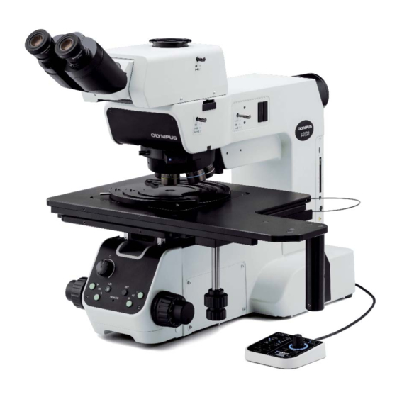
MX63/MX63L
Semiconductor/FPD/Industrial Inspection
Microscopes
Notes
This instruction manual is for the Olympus microscope.
Optical Microscope and Accessory
To ensure safety, obtain optimum performance and to familiarize yourself fully with the use of this
product, we recommend that you study this manual thoroughly before operating this product, and
always keep this manual at hand when operating this product.
Retain this instruction manual in an easily accessible place near the work desk for future reference.
For details of products included in the configuration of this microscope, see page 18.
Advertisement
Table of Contents

Related Manuals for Olympus MX63


Summary of Contents for Olympus MX63
- Page 1 Semiconductor/FPD/Industrial Inspection Microscopes Notes This instruction manual is for the Olympus microscope. Optical Microscope and Accessory To ensure safety, obtain optimum performance and to familiarize yourself fully with the use of this product, we recommend that you study this manual thoroughly before operating this product, and always keep this manual at hand when operating this product.
- Page 2 Refer to your local Olympus distributor in EU for return and/or collection systems available in your country. NOTE: This product has been tested and found to comply with the limits for a Class A digital device, pursuant to Part 15 of the FCC Rules.
-
Page 3: Table Of Contents
MX63/MX63L Contents Introduction ............................... 1 Safety precautions ............................2 1 Nomenclature of units ........................13 2 List of combinable units .........................18 3 Observation procedures ........................ 22 3-1 Reflected light brightfield/darkfield observation procedures ........22 3-2 Main switch ................................24 3-3 Selecting the observation method (BF/DF) ................25 3-4 Selecting between the eyepiece light path and the camera light path ....26... - Page 4 3-9 Adjusting the observation tube ......................35 Adjusting the interpupillary distance ........................35 Adjusting the diopter ................................35 Using the eye shades ................................37 Adjusting the tilt ...................................37 3-10 Adjusting the aperture diaphragm ....................38 3-11 Using the filter for reflected light illumination ............... 39 3-12 Setting the glare prevention ........................
- Page 5 MX63/MX63L 5-6 Reflected light simultaneous observation for BF/DF observation procedures .....57 Inserting the MIX slider for reflected light observation ................58 Turning ON the illumination of the MIX slider for reflected light observation .......58 Adjusting the illumination brightness ........................59 Selecting the illumination pattern ..........................60 5-7 Transmitted light simple polarization observation procedures ......
- Page 6 11 Maintenance parts ........................105 12 Preventive inspection sheet for illumination devices ........106 13 Proper selection of the power supply cord ............107 Appendix: Units attached by Olympus ................109 Transmitted light illumination unit (MX-TILLA/MX-TILLB) ...............109 Setting the OP light path..............................110 Attaching the reflected light filter (26ND0.5) ....................111...
-
Page 7: Introduction
(There are other units usable with the UIS series. Contact Olympus or refer to the latest catalogs.) This instruction manual applies to users of this product and Olympus distributors. However, some part at the end of this instruction manual applies to Olympus distributors only. -
Page 8: Safety Precautions
· Install the product on an desk where the tilt of the top surface of the desk meets following conditions. Otherwise, the stage may move spontaneously. ・ MX63 : 1° or less ・ MX63L : 20′ or less · For safety, do not place a mat, etc. under the device. - Page 9 MX63/MX63L CAUTION - Electric safety - Always use the power cord provided by Olympus. If the proper the power cord and cables are not used, the electric safety and the EMC (Electro-Magnetic Compatibility) performance of the product cannot be assured. If no power cord is provided, please select the proper power cord by referring to the section “Proper selection of the power cord”...
- Page 10 · Since the lamp generates a high heat, perform the inspection according to “12 Preventive inspection sheet for illumination devices" on page 106. If you find the unexpected phenomena, e.g. smoke, etc. during operation, turn OFF the power immediately and contact Olympus.
- Page 11 CAUTION - Prevention of fire - Do not repair, disassemble or remodel. Never repair, disassemble or remodel this product. Otherwise, fire may result. The repair work must not be carried out except those authorized by Olympus. If you need repairs, contact Olympus for assistance.
- Page 12 L42 filter slider (U-25L42) / High temperature Light balancing filter slider (U-25LBD) / Yellow filter slider (U-25Y48) / Empty slider (U-25) / Light balancing amber filter slider (U-25LBA) When caution labels are dirty or peeled off, contact Olympus for replacement or inquiries.
- Page 13 If you need to pack this product for shipping to a distant location, etc., the dedicated transport tools and packaging materials are necessary. Be sure to contact Olympus for assistance. Handling Precautions · This product is a precision instrument. Handle it with care and avoid subjecting it to a sudden or severe NOTE impact.
- Page 14 · The following installation space is set according to the SEMI standard guidelines (SEMI S8-0915). It is recommended to secure the appropriate installation space suitable for your operation referring to the following installation space, appearance of the system, eye point height, etc. MX63 installation space Unit: mm...
- Page 15 MX63/MX63L MX63L installation space Unit: mm...
- Page 16 MX63 appearance, eye-point and center of gravity Unit: mm The center of gravity is an approximate position in the standard combination for transmitted light observation. Note that the position varies depending on the sample weight, stage position and other units to be combined.
- Page 17 MX63/MX63L MX63L appearance, eye-point and center of gravity Unit: mm The center of gravity is an approximate position in the standard combination for transmitted light observation. Note that the position varies depending on the sample weight, stage position and other units to be...
- Page 18 5. Before disposing of this product, be sure to check the regulations and rules of your local government and follow them. Contact Olympus for any questions. 6. If the hour counter of the power supply (U-RFL-T) shows 300 hours, set the main switch to (OFF) for safety purpose, wait 10 minutes or more and replace the lamp.
-
Page 19: Nomenclature Of Units
Light source for reflected light illumination Revolving nosepiece Observation tube Eyepiece Intermediate attachment* Objective series Breath shield Stage Stage Microscope frame Hand switch For other units combinable with the microscope which are not described here, contact Olympus or refer to the latest catalogs. - Page 20 Stage holder for MX63 Rotary wafer holder For 3 or 4 inches (BH2-WHR43) For 4 or 5 inches (BH2-WHR54) For 5 or 6 inches (BH2-WHR65) Rotary wafer holder plate For 6 or 8 inches (MX-WHPR86) Rotary wafer holder plate (BH3-WHP6)
- Page 21 MX63/MX63L Stage holder for MX63L 6-inch mask holder Glass plate Rotary wafer holder for 8-inch and 12-inch (MX-MH6) (MX-SPG1412) (MX-WHPR128) Coarse adjustment grip (page 27) X-axis/Y-axis knobs (page 27) X-axis/Y-axis knobs (page 27) (with a crutch) 14x12-inch stage (MX-SIC1412R2)
- Page 22 Mirror unit Various mirror units are available according to the purposes of observation. Observation Mirror unit names Reflected light brightfield Built-in the arm of microscope frame Reflected light darkfield Reflected light DIC U-MDIC3, U-MDICAF3 Reflected light simple U-MDIC3, U-MDICAF3 polarization U-MWBS3, U-MWGS3, U-MWUS3 Reflected light fluorescence U-MF2 (optional idle mirror unit frame)
- Page 23 MX63/MX63L The transmitted light illumination unit is attached by Olympus. The following illustration shows the view without stage in order to show the condenser without obstacle. Transmitted light illumination unit (MX-TILLB) Condenser height adjustment ring (page 47) Filter insertion slot (page 49)
-
Page 24: List Of Combinable Units
Transmitted light Observation method Brightfield/ Differential Simple Simple Brightfield Darkfield darkfield interference Fluorescence Infrared Brightfield polarization polarization Units simultaneously contrast Microscope frame MX63-F MX63L-F Observation tube U-TR30-2 U-ETR-4 U-TTR-2 U-SWTR-3 U-SWETTR-5 MX-SWETTR U-BI30-2 U-TBI-3 U-TLU U-TR30IR U-TLUIR Intermediate U-CA attachment... - Page 25 MX63/MX63L : Combination available (including units with restrictions) : Combination prohibited : Unnecessary for observation Reflected light Transmitted light Observation method Brightfield/ Differential Simple Simple Brightfield Darkfield darkfield interference Fluorescence Infrared Brightfield polarization polarization Units simultaneously contrast Light sources U-LLG150...
- Page 26 U-HSEXP TH4-HS Breath shield MX-BSH-ESD-2 Eyepiece WHN10X WHN10X-H CROSSWHN10X SWH10X-H CROSS-SWH10X Immersion oil IMMOIL-F30CC Objective See “9 Optical performance list <<UIS2 series>>" on page 84. Olympus classifies MX63-F, MX63L-F as an optical microscope and other units as optical microscope accessories.
- Page 27 MX63/MX63L Memo...
-
Page 28: Observation Procedures
Observation procedures 3-1 Reflected light brightfield/darkfield observation procedures This section describes the operating procedures of the reflected light brightfield/darkfield observations which are the basis of observation methods. The differential interference contrast observation, simple polarization observation, etc. are described in “5 Observation methods" on page 44. When using only the reflected light illumination while the transmitted light illumination unit is installed, set NOTE the aperture diaphragm on the front of the base of microscope frame to the minimum position or insert the... - Page 29 MX63/MX63L Observation light path Light path selection knob (P.26) selection knob (P.25) Diopter adjustment ring (P.35) Filter insertion slot (P.39) Interpupillary distance Interpupillary distance adjustment scale (P.35) adjustment scale (P.35) Light intensity knob (P.32) Analyzer insertion slot (P.51) Analyzer insertion slot (P.51) Stage plate (P.27)
-
Page 30: Main Switch
3-2 Main switch Rotate the light intensity knob a counterclockwise fully and set the main switch b to (ON). In case of emergency, disconnect the power cord from CAUTION the product , and set the main switch to (OFF) to shut down the power supply. -
Page 31: Selecting The Observation Method (Bf/Df)
The 2-level selection (BF DF) is set as factory default. However, if the optional mirror unit is attached (by the Olympus representative), the 3-level selection is available. When the hand switch is combined The lighting of the CUBE indicator b of the hand switch (BX3M-HS) is changed according to the selection of the observation method selection knob. -
Page 32: Selecting Between The Eyepiece Light Path And The Camera Light Path
3-4 Selecting between the eyepiece light path and the camera light path This function is available when the trinocular tube is combined. You can select the light path for observing with the eyepiece or the light path for observing with the display, etc. through the camera. Slide the light path selection knob a of the trinocular tube to select the required light path. -
Page 33: Placing A Sample
MX63/MX63L 3-5 Placing a sample Placing a sample The maximum weight loadable on the stage is described below (including holders). · MX-SIC8R/MX-SIC6R: 2 kg · MX-SIC1412R: 3.5 kg If the sample exceeding the specified weight is placed NOTE on the stage, the feeling of stage movement will be deteriorated or the stage will be worn out. -
Page 34: Selecting The Objective
3-6 Selecting the objective · In order to prevent the sample from colliding with the NOTE objective, be sure to change the objective in order from the low magnification to the high magnification before focusing. · Do not rotate the revolving nosepiece directly with hand. Rotating by hand may damage the gear heads or cause other malfunctions. -
Page 35: Focusing
MX63/MX63L 3-7 Focusing Focusing Rotate the coarse focusing knob a and the fine focusing knob b in the arrow direction to move the stage upward. (The sample approaches the objective.) Adjusting the tension of the coarse focusing knob The tension of the coarse focusing knob is pre-adjusted for easy use, but if you wish, you can change the tension. -
Page 36: Using The Pre-Focusing Lever
Using the pre-focusing lever Using the pre-focusing lever controls the vertical movement of the stage no further than the arbitrary position when rotating the pre-focusing lever. With this function, the approximate focal position can be reproduced or the collision between the stage and the objective can be prevented. Note, even though the pre-focusing lever is used, the vertical movement of the stage is not restricted with the fine focusing knob. -
Page 37: Using The Focus Aid (Mx-Fa)
Using the focus aid (MX-FA) When observing the sample with flat and mirror surface, use the focus aid (MX-FA) to bring the sample into focus easily. Contact Olympus for attaching the focus aid. · The focus aid is available only with the reflected... -
Page 38: Adjusting The Brightness
3-8 Adjusting the brightness When the LED lamp housing is combined Rotate the light intensity knob a clockwise to make the illumination light brighter. When the mercury lamp housing is combined Adjust the collector lens focusing knob a to make the entire field of view brightest evenly. -
Page 39: When The Light Source Is Combined
MX63/MX63L When the light source is combined Rotate the light intensity adjustment dial a of the light source (U-HGLGPS) to adjust the light intensity. The light intensity can be adjusted in 7 levels. The number indicates the percentage (0 to 100%) of each light intensity when the maximum light intensity is 100%. - Page 40 Procedure to replay the brightness Press the LIM switch a to set the "Replay" mode. (LIM switch a is ON.) When you select the desired objective or the observation method, the stored brightness is set automatically. Restoring the stored brightness (LIM function) to the factory default setting Set the main switch of the microscope frame to (OFF).
-
Page 41: Adjusting The Observation Tube
MX63/MX63L 3-9 Adjusting the observation tube Adjusting the interpupillary distance The adjustment of the interpupillary distance is to adjust the distance between two eyepieces to fit to the distance between your two eyes. By doing so, you can see the single microscope image so that the fatigue of your eyes during observation can be reduced. - Page 42 When the eyepiece is equipped with the eyepiece micrometer While looking through the eyepiece equipped with the eyepiece micrometer, rotate the diopter adjustment ring b to adjust so that the scales or lines of the eyepiece micrometer in the field of view are clearly visible.
-
Page 43: Using The Eye Shades
MX63/MX63L Using the eye shades When wearing eyeglasses Use the eye shades in the folded-down position. When not wearing eyeglasses Raising the folded-down eyeshades in the arrow direction prevents the unnecessary light from entering between eyepieces and eyes. Adjusting the tilt This function is available when U-TBI-3, U-TTR-2, MX-SWETTR or U-SWETTR-5 is combined. -
Page 44: Adjusting The Aperture Diaphragm
3-10 Adjusting the aperture diaphragm The aperture diaphragm is used to adjust the numerical aperture of the illumination system. Matching the numerical aperture of the illumination system with that of the objective to be used offers an image with optimum contrast and also increases the focal depth of image. However, this adjustment may decrease the resolution and brightness. -
Page 45: Using The Filter For Reflected Light Illumination
MX63/MX63L 3-11 Using the filter sliders for reflected light illumination Insert the filter slider suitable for the intended observation into the filter insertion slot (2 positions) a to engage in the light path. The first level (position where the clicking sound is heard first) is an empty hole. -
Page 46: Setting The Glare Prevention
3-12 Setting the glare prevention When using the LED illumination, it is designed to turn OFF the LED illumination only when changing objectives in order to prevent the glare during objective change. When using the halogen bulb, you can set the aperture diaphragm to the CLOSE position during objective change to prevent the glare. -
Page 47: Observation Using The Mercury Burner
BF observation light path. In such a case, insert this filter in the BF light path to prevent your eyes from bright light. This filter is provided with the adapter (MX-HGAD). Contact Olympus for attaching the filter. -
Page 48: Using The Oil Immersion Objective
Apply the specified oil (immersion oil) to the tip of the oil immersion objective. Otherwise, the observation image can not be brought into focus. Always use the immersion oil made by Olympus. If you NOTE use the immersion oil other than those made by Olympus, the correct optical performance cannot be exhibited. -
Page 49: Image Acquisition
MX63/MX63L Image acquisition 4-1 Image acquisition diagram Attaching the camera adapter and the microscope digital camera to the trinocular tube allows you to acquire the observed image. The image acquisition range is determined by the size of the image sensor used in the camera and the magnification of the camera adapter. -
Page 50: Observation Methods
Observation methods The dummy slider in the DIC prism insertion slot is effective for preventing flare in observations other than the DIC observation. It is, therefore, recommended to leave it mounted in any observation method. Setting the DF light path prevents the half mirror from entering the transmitted light illumination light path. Therefore, the transmitted light can be used most effectively. - Page 51 MX63/MX63L Use the stage MX-SIC1412R2 or MX-SIC8R that is applicable for transmitted light observation. The transmitted light illumination range of the applicable stage is described below. (MX-TILLA) is used, * When the transmitted light illumination unit it is MX-SIC1412R2 *...
-
Page 52: Notes For Observation
Notes for observation · The objectives should be between 5X and 150X. · The thickness of the observable sample should be between 0 and 9 mm (MX-TILLB) or between 0 and 3 mm (MX-TILLA) including the thickness 6 mm of the glass plate (BH3-SPG6, MX-SPG1412). ·... -
Page 53: Using The Field Diaphragm For Transmitted Light Illumination
MX63/MX63L Using the field diaphragm for transmitted light illumination This function is available only with the transmitted light illumination unit ( MX-TILLB). Adjusting the field diaphragm appropriately offers the observed images with better contrast and few flare. This function is available with objectives between 5X and 150X. -
Page 54: Using The Aperture Diaphragm For Transmitted Light Illumination
Using the aperture diaphragm for transmitted light illumination In general, adjusting the aperture diaphragm to 70% to 80% of the numerical aperture of the objective allows you to obtain an image with good contrast. However, the NA may become insufficient when using the objectives with NA0.6 (MX-TILLB) or NA0.5 (MX-TILLA) or higher. -
Page 55: Using The Filters For Transmitted Light Illumination
MX63/MX63L Using the filters for transmitted light illumination Filters can be inserted to three positions described below. Note, as the filter at the tip of the light guide is a built-in type, it is recommended to attach the constantly-used color temperature conversion filter 25LBD (for converting the illumination light to the daylight color). -
Page 56: Reflected Light Differential Interference Contrast (Dic) Observation Procedures
5-2 Reflected light differential interference contrast (DIC) observation procedures For this observation, the DIC mirror unit (U-MDIC3 or U-MDICAF3) must be attached to the OP position of the observation light path by Olympus. U-MDIC3: The analyzer and the polarizer are built-in. -
Page 57: Setting The Analyzer (When Using U-Mdicaf3)
MX63/MX63L Setting the analyzer (when using U-MDICAF3) When using the mirror unit (U-MDIC3), it is not necessary to set the analyzer or adjust the crossed nicols. If the DIC slider is engaged in the light path, remove it from the light path. -
Page 58: Setting The Dic Slider
Setting the DIC slider Loosen the mounting knob a at the rear right of the revolving nosepiece and pull out the dummy slider b . Insert the DIC slider c for reflected light observation in the slider insertion slot of the revolving nosepiece with the display surface facing up, and stop inserting at the first level (when the clicking sound is heard at first). -
Page 59: Adjusting The Prism Of The Dic Slider
MX63/MX63L Adjusting the prism of the DIC slider Rotate the prism movement knob a of the DIC slider to select the interference color with the highest contrast suitable for the sample. U-DICR, U-DICRHC The interference color of the background changes continuously from the gray sensitive color to the magenta sensitive color (from -100 to 600 nm). -
Page 60: Reflected Light Simple Polarization Observation Procedures
5-3 Reflected light simple polarization observation procedures · The performance of the polarizer may be deteriorated if it is exposed to the light for a long period NOTE (approx. 2000 hours continuously). If this happens, replace the polarizer. · When using the mercury lamp housing, be sure to use the U-25L42 filter to prevent the polarizer from tarnish. -
Page 61: Reflected Light Fluorescence Observation Procedures
To compensate this difference, insert the ND filter (26ND0.5) provided with the adapter (MX-HGAD) in the brightfield observation light path. (For attaching the mirror unit, contact Olympus.) If the observation light is too bright, insert the ND filter to reduce the light. -
Page 62: Reflected Light Ir (Infrared) Observation Procedures
CAUTION To improve the IR observation effect, use as many IR-dedicated units as possible (such as the lamp housing, objective, observation tube, camera adapter, etc.). For IR-dedicated units, contact Olympus. Notes for using the infrared · The infrared light generates the significant heat on the sample surface. Pay a careful attention to the sample which is vulnerable to heat. -
Page 63: Reflected Light Simultaneous Observation For Bf/Df Observation Procedures
MX63/MX63L 5-6 Reflected light simultaneous observation for BF/DF observation procedures Operation part Page Main switch P.24 Set the main switch to (ON). Select BF (reflected light brightfield observation). Observation light path selection knob P.25 [Trinocular tube only] Light path selection knob P.26... -
Page 64: Inserting The Mix Slider For Reflected Light Observation
Inserting the MIX slider for reflected light observation Loosen the mounting knob a at the rear right of the revolving nosepiece and pull out the dummy slider b . Insert the MIX slider for reflected light observation (U-MIXR) c to the slider insertion slot of the revolving nosepiece so that the connector comes to the right side, and push it in the second level (position where the clicking sound is heard). -
Page 65: Adjusting The Illumination Brightness
MX63/MX63L Adjusting the illumination brightness Press the light intensity button a of the hand switch (BX3M-HS) to adjust the brightness of the illumination. Button Operation Function Short press Darken by predetermined quantity. Long press Darken continuously. Short press Brighten by predetermined quantity. -
Page 66: Selecting The Illumination Pattern
Selecting the illumination pattern Press the MODE button a of the hand switch (BX3M-HS) to select the illumination pattern. The indicator b turns ON according to the illumination pattern. State Indicator ( b , c ) Function Turns ON. The illumination turns ON. Turns OFF. -
Page 67: Transmitted Light Simple Polarization Observation Procedures
MX63/MX63L 5-7 Transmitted light simple polarization observation procedures This observation requires the analyzer and the polarizer. However, if the mirror unit (U-MDICT3 or U-MDIC3) is engaged in the (OP) light path, the built-in analyzer can be used. Operation part Page... -
Page 68: Setting The Analyzer And The Polarizer For Transmitted Light Illumination
Setting the analyzer and the polarizer for transmitted light illumination When (OP) is selected for observation light path Insert the polarizer (U-PO3) a in the polarizer insertion slot. Polarizer insertion position Light path First level (pulled out) Empty hole Second level (pressed in) Polarizer When DF is selected for observation light path If the DIC slider is engaged in the light path, remove it from the light path. -
Page 69: Replacement Of Optical Parts
MX63/MX63L Replacement of optical parts 6-1 Removing and attaching the eyepiece Removing the eyepiece Pull out the eyepiece a from the eyepiece sleeve b . Attaching the eyepiece micrometer You can use the eyepiece micrometer to check the size of the observed image or the center position of the observation field of view, etc. - Page 70 Attaching the eyepiece Insert the eyepiece a into the eyepiece sleeve b until it touches the end. · As the binocular tube does not have a positioning groove, NOTE it cannot be used with an eyepiece equipped with a positioning pin. ·...
-
Page 71: Replacing The Objective
MX63/MX63L 6-2 Replacing the objective When replacing the objective, remove the revolving nosepiece from the microscope frame before NOTE replacing the objective. If you attach the objective without removing the revolving nosepiece, the objective will be screwed upward (direction opposite to gravity). So, it will be difficult to screw the objective fully into the revolving nosepiece to secure firmly. - Page 72 Removing and attaching the objective Place the revolving nosepiece on the desk with the objectives facing up. Rotate the objective in the arrow direction to remove the objective from the revolving nosepiece. Attach the objective to the objective mounting screw a from No.1 to 5 or No.
- Page 73 MX63/MX63L Attaching the revolving nosepiece Only U-D5BDREMC, U-D6REMC, U-P5REMC, NOTE U-P5BDREMC and U-D6BDREMC are available with this microscope. Rotate the coarse focusing knob to lower the stage sufficiently. Loosen the revolving nosepiece clamping screw a using the Allen screwdriver provided with microscope frame.
-
Page 74: Replacing The Halogen Bulb
6-3 Replacing the halogen bulb The bulb, lamp housing and areas around the lamp housing are extremely hot during and right after use. CAUTION When replacing the burner during observation, set the main switch to (OFF) and disconnect the power cord. - Page 75 MX63/MX63L While pressing down the bulb fixing lever d , hold the halogen bulb e wrapped with gauze, etc. and insert the terminal f until it touches the pin position g . Place the bulb fixing lever carefully to the original position to secure the bulb.
-
Page 76: Replacing The Mercury Burner
6-4 Replacing the mercury burner Applicable lamp USH-103OL (made by Ushio Co.) Removing the mercury lamp housing Set the main switch of the power supply for mercury burner (U-RFL-T) (OFF) and disconnect the power cord. Remove the connector of the lamp housing from the power supply (U-RFL-T). - Page 77 MX63/MX63L Place the socket part so that the heat radiating fin c faces down. Loosen the burner mounting screws d (2 positions) of the socket part. Hold the mercury burner e attached and remove the lower side from the mount first and then remove the upper side.
- Page 78 * The 26ND0.5 filter must be attached by the Olympus representative. Connect the cable of the mercury lamp housing to the power supply (U-RFL-T). For details, refer to the instruction manual provided with the unit.
- Page 79 MX63/MX63L Centering the mercury lamp housing The mercury burner emits the light by means of discharge produced when a current is supplied across electrodes. Therefore, the electrode positions must be adjusted by replacing the burner, etc. This operation to adjust the electrode positions is called the centering of the mercury burner.
- Page 80 Push the aperture diaphragm open/close button and open the aperture diaphragm. Rotate the collector lens focusing knob a to project the arc image on the U-CST. (Picture A) If the arc image is not projected, rotate the burner centering knobs b . If it is difficult to use the collector lens focusing knob of the mercury lamp housing because it is placed at the back of the microscope, insert the extension handle (U-CLA) c in the...
-
Page 81: Replacing The Filter
MX63/MX63L 6-5 Replacing the filter The filters are very hot immediately after use. Make sure that the filters are cooled down sufficiently CAUTION before replacing the filters. The arbitrary filter with the following size can be inserted to the empty slider (U-25). -
Page 82: Troubleshooting
Troubleshooting If problems occur, please review the following list and take remedial action as needed. If you cannot solve the problem after checking the entire list, please contact Olympus for assistance. Problem Cause Remedy Page 1. Optical systems a) Even though the lamp is ON, The lamp is burned out. - Page 83 MX63/MX63L Problem Cause Remedy Page 2. DIC observation a) The interference color does not The analyzer and the mirror unit Insert the analyzer and the mirror 25, 51 appear. are not in the light path. unit in the light path properly.
- Page 84 ON. the back of the microscope frame. The microscope frame or the LED Contact Olympus. — lamp housing is damaged. f) The brightness cannot be relay The LIM switch is not pressed (LIM Press the LIM switch to set the when the LIM function is set.
- Page 85 MX63/MX63L Problem Cause Remedy Page i) The system cannot be The interface cable is not Connect the interface cable. controlled by PC. connected. Close the application software. The main switch is set to (OFF) Then, set the main switch to (ON)
- Page 86 PC and frame and PC is turn ON again. disconnected. The control board is Contact Olympus. — damaged. “4" blinks b) The blinking starts when The aperture diaphragm Engage the 10X objective 4 times.
- Page 87 Repair request If you cannot solve the problems even though taking actions described in Troubleshooting, please contact Olympus for assistance. At that time, please tell them the following information as well. · Product name and abbreviation (Example: Stage MX-SIC8R) ·...
-
Page 88: Specifications
Equipped with tension adjustment mechanism and upper limit stopper mechanism Rating: 100-120/220-240Vac 0.5/0.3A 50/60Hz Maximum loadable weight (including stage and holders): MX63: 8 kg MX63L: 15 kg External interface: RS-232C (2m external cable is included, D-SUB 9-pin female straight connector) USB2.0 (2m external cable is included) - Page 89 MX63/MX63L Configuration units Product name Specifications Light source LED light LG-LSLED White LED source for for transmitted Average lifetime: Approx. 60,000 hours (Value derived by calculating the light guide LED element alone based on LM80/TM21) light illumination Revolving Motorized U-D6REMC...
-
Page 90: Optical Performance List <
NOTE combination with this product even though For brightfield/darkfield they are not listed here. Contact Olympus for details. Objective field number ** Cover glass thickness - : Use either with or without the cover glass 0 : Use without the cover glass ** “FN”... - Page 91 MX63/MX63L Basic information by objective Eyepiece Optical performance Working Cover glass WHN10X (FN22) SWH10X (FN26.5) Numerical Magnification distance thickness Actual field Actual field aperture Total Total (mm) (mm) of view of view magnification magnification Series name Notation (mm) (mm) UIS2 series...
- Page 92 Eyepiece Optical performance Working Cover glass WHN10X (FN22) SWH10X (FN26.5) Numerical Magnification distance thickness Actual field Actual field aperture Total Total (mm) (mm) of view of view magnification magnification Series name Notation (mm) (mm) UIS2 series SLMPLN SLMPlanN 0.25 25.0 200X 200X 1.33...
- Page 93 MX63/MX63L Abbreviations used for objective (Plan) None: For brightfield BD: For brightfield/darkfield BDP: For brightfield/darkfield, polarization IR: For IR Number: Objective magnification None: UIS objective N: UIS2 objective None: Achromat: Corrects the aberration by 2 wavelengths (blue and red). FL: Semi-apochromat: Corrects the color aberration in the visible range (from blue-violet to red).
-
Page 94: Assembly
10-1 Assembly diagram The numbers in the following diagram represent the order to attach each unit. The units shown in the diagram are typical units. For units which are not described below, contact Olympus or refer to the latest catalogs. -
Page 95: Assembly Procedures
MX63/MX63L 10-2 Assembly procedures This product contains the motorized parts. For safety purpose, connect the power cord plug last. CAUTION Attaching the stage Remove the transport clamping plate a from the back of the stage using the Allen wrench. The removed screws are used to secure the stage when attaching it. -
Page 96: Attaching The Holders
However, if the finer adjustment is required or when using a non-Olympus holder, apply drops of alcohol on screws e to loosen the screw lock. Then, move the screws up and down... -
Page 97: Attaching The Objective
MX63/MX63L Attaching the objective For attaching procedures, see “Removing and attaching the objective" (P.66). Attaching the revolving nosepiece For attaching procedures, see “Attaching the revolving nosepiece" (P.67). Attaching the MIX slider / DIC slider for reflected light observation For attaching procedures, see “Inserting the MIX slider for reflected light observation"... -
Page 98: Attaching The Light Source For Reflected Light Illumination
Attaching the light source for reflected light illumination Attaching the LED illumination Loosen the mounting screw a (2 positions) on the microscope frame using an Allen screwdriver. Be careful, if the mounting screw is loosened too much, it NOTE may be come off. Insert the reflected LED light source or the liquid light guide adapter into the light source mounting hole of the microscope frame until it touches the end. - Page 99 · Attach the double lamp housing adapter (U-DULHA) so that the illuminator a comes to the left side horizontally when facing to the back side of the microscope frame. << Attaching to MX63 >> Double lamp housing adapter U-DULHA...
- Page 100 << Attaching to MX63L >> Adapter MX-HGAD Double lamp housing adapter U-DULHA Darkfield converter U-RCV Reflected LED light source Mercury lamp BX3M-LEDR Light guide adapter housing U-LLGAD U-LH100HG U-LH100HGAPO Halogen lamp housing U-LH100L-3 Layout of the extension cable for reflected LED light source If you want to connect the light source for reflected LED to the microscope frame using the double lamp housing adapter (U-DULHA), the extension cable (MX-LLHECBL) is required.
-
Page 101: Attaching The Breath Shield Mx-Bsh-Esd-2
MX63/MX63L Attaching the breath shield MX-BSH-ESD-2 After the revolving nosepiece attached, attach the breath NOTE shield. Attach the breath shield mounting fixture a on the breath shield b temporarily using the provided screws (shorter ones) with the Allen screwdriver. (2 positions) -
Page 102: Connecting The Cables
Connecting the cables Always use the USB cables and RS-232C cable interface cables provided by Olympus. If you use the CAUTION commercially available USB2.0 cables or hubs, the system operations cannot be ensured. · Before connecting or disconnecting cables, set the main switch to... - Page 103 MX63/MX63L Layout of the cable for MIX slider for reflected light observation Attach the cable holders at 2 positions ( a , b ) on the side surface of the microscope frame. The cable holders (3 pcs.) are provided with the cable for MIX slider (U-MIXRCBL).
-
Page 104: Setting The Dip Switch / As.preset Switch
Setting the DIP switch / AS.PRESET switch Setting the DIP switch Make sure that the connections are correct. Before setting the DIP switch a , set the main switch of the microscope (OFF). The switch settings are read and defined only when the power is turned ON. - Page 105 MX63/MX63L Setting the AS.(aperture diaphragm) PRESET switch Setting the AS (aperture diaphragm) diameter per each objective using the AS PRESET switches b allows you to change the AS diameter to the AS diameter value specified according to the selected objective.
- Page 106 AS interlocking When the brightfield observation or the option mirror unit are selected as the observation light path, pressing the objective selection button on the front panel will change the AS diameter to the setting value when the objective is selected. If the AS switch diameter is set while the main switch is set to (OFF), the AS diameter is changed to the setting value per each objective when the power is turned.
-
Page 107: Connecting The Power Cord
· Set the main switch a to (OFF) and connect the power cord. · Always use the power cord provided by Olympus. Insert the power cord connector b in the connector c . · Connect the power cord to the grounded triplex outlet. -
Page 108: Use Of The Adjuster
Use of the adjuster The center of gravity changes depending on the sample weight, sample position or stage movement, etc. In particular, as MX63L uses a large- size stage, the center of gravity changes significantly. To prevent the microscope from unexpected overturning, adjust the adjuster at the bottom of the microscope to take the overturning prevention actions. -
Page 109: Centering Of The Aperture Diaphragm Of Reflected Light Illumination
MX63/MX63L Centering of the aperture diaphragm of reflected light illumination Set the observation light path selection knob a to the BF position. Press the objective selection button b to engage the 10X objective in the light path and bring the sample into focus approximately. -
Page 110: Connection With Pc
10-3 Connection with PC To control this system from PC, PC must be connected to the microscope frame with the interface cable (USB cable or RS-232C cable). In addition, the application software to control this system must be installed on PC. Connecting the interface cable ·... -
Page 111: Maintenance Parts
Olympus immersion oil IMMOIL-F30CC 11-2 List of chemicals used for maintenance · Olympus immersion oil : IMMOIL-F30CC Obtain the Safety Data Sheet from the Website of Olympus Corporation. · Absolute alcohol* (commercially-available product) · Neutral detergent* (commercially-available product) * Obtain the Safety Data Sheet from the supplier where you purchased this commercially-available product. -
Page 112: Preventive Inspection Sheet For Illumination Devices
· The table below identifies the check items to be observed. Put (X) if not applicable or ( ) if applicable. · If there are any check marks, immediately stop using the product and request inspection to Olympus or replace with new illumination device(s). -
Page 113: Proper Selection Of The Power Supply Cord
If no power supply cord is provided, please select the proper power supply cord for the equipment by referring to “Specifications” and “Certified Cord” below: Caution : In case you use a non-approved power supply cord for Olympus products, Olympus can no longer warrant the electrical safety of the equipment. - Page 114 Table 2 HAR flexible cord Approval organizations and cordage harmonization marking methods Alternative marking utilizing Printed or embossed black-red-yellow thread (Length harmonization marking (May be of color section in mm) Approval organization located on jacket or insulation of internal wiring) Black Yellow Comite Electrotechnique Belge...
-
Page 115: Appendix: Units Attached By Olympus
MX63/MX63L Appendix: Units attached by Olympus assembled and adjusted The units described below must be by Olympus. If these units are assembled or adjusted by the customer, the operations are not ensured. Transmitted light illumination unit (MX-TILLA/MX-TILLB) Units must be attached carefully to prevent them from NOTE leaving fingerprints or scratches. -
Page 116: Setting The Op Light Path
Setting the OP light path If you need to attach the reflected light filter, attach it together with this setting. (See next page.) Loosen the clamping screws on the top cover a using the Allen screwdriver (2 mm) to remove the top cover. Rotate the observation light path selection knob b counterclockwise to remove it. -
Page 117: Attaching The Reflected Light Filter (26Nd0.5)
MX63/MX63L Attaching the reflected light filter (26ND0.5) Loosen the clamping screws on the top cover a using the Allen screwdriver (2 mm) to remove the top cover. Rotate the observation light path selection knob b counterclockwise to remove it. (This selection knob should be retained by the user because it will be reused when restoring the light path switching stroke to the original setting.) -
Page 118: Attaching The Focus Aid (Mx-Fa)
Attaching the focus aid (MX-FA) Loosen the clamping screws on the top cover a using the Allen wrench (2 mm) to remove the top cover. Peel off the sticker b of the focus aid knob insertion slot. Push the focus aid unit in back-left direction (arrow direction d in the picture) facing from the right side of the microscope, and secure it using the clamping screws e (2 positions). - Page 120 Manufactured by Shinjuku Monolith, 2-3-1 Nishi-Shinjuku, Shinjuku-ku, Tokyo 163-0914, Japan Distributed by AX8974 02 Issued in May, 2019...
Need help?
Do you have a question about the MX63 and is the answer not in the manual?
Questions and answers