Table of Contents
Advertisement
ASSEMBLY/SETUP
MANUAL
MX61/MX61 L
200mm/300mm COMPATIBLE SEMICONDUCTOR/FPD
INSPECTION MICROSCOPES
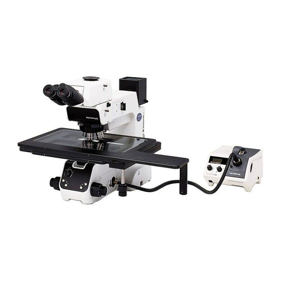
This manual is for assembly and setup of the Olympus MX61/MX61L Semiconductor/FPD
Inspection Microscopes. To ensure the safety, obtain optimum performance and familiarize yourself
fully with the use of this microscope, we recommend that you study this manual thoroughly before
operating the microscope. As this manual will be needed when you replace the lamp or fuses or
modify a setup, retain it in an easily accessible place near the work desk for future reference.
A X 7 5 9 9
Advertisement
Table of Contents

Related Manuals for Olympus MX61


Summary of Contents for Olympus MX61
- Page 1 200mm/300mm COMPATIBLE SEMICONDUCTOR/FPD INSPECTION MICROSCOPES This manual is for assembly and setup of the Olympus MX61/MX61L Semiconductor/FPD Inspection Microscopes. To ensure the safety, obtain optimum performance and familiarize yourself fully with the use of this microscope, we recommend that you study this manual thoroughly before operating the microscope.
- Page 3 8-10 ASSEMBLY 11-24 2-1 Assembly Diagram ................................... 11 2-2 Detailed Assembly Procedures ........................... 12-22 2-3 Modules Installed by Olympus ..........................23-24 Transmitted Light Module (MX-TILLA/TILLB) (Optional) Light Path Setup Reflected Neutral Density Filter (ND 0.5) CENTRATION OF THE MERCURY/XENON BURNER...
- Page 4 UIS2 (UIS) eyepieces, objectives, observation tubes, etc. Less-than-optimal performance may result if inappropriate accessories are used. The MX61L microscope is compatible with a stage stroke of 300 mm (12 inches) and the MX61 microscope is compatible with that of 200 mm (8 inches).
- Page 5 5. The desktop surface on which the microscope system is installed should be almost horizontal with a tilting angle of less than 20’ with the MX61L or less than 1° with the MX61 (to prevent spontaneous displacement of the stage) and rigid.
- Page 6 MX61 installation space Unit: mm MX61 Stage movement range Installation space MX61L external view, eye point and center of gravity Unit: mm Eye point Position of center of gravity (Bottom view of microscope) (Note) The center of gravity is an approximate position when the microscope is equipped with the standard module combination for transmitted light observation.
- Page 7 9. To prevent toppling of the microscope system, keep the total height of the microscope below 1 meter (3.3 ft) when attachments (including Olympus optional modules and the CCD camera prepared by the customer) are mounted. 10. Each microscope has screw holes (M5, depth 10 mm) for prevention of toppling (in the case of an earthquake or microscope imbalance) on the ²...
- Page 8 Safety Symbols The following symbols are found on the microscopes. Study the meaning of the symbols and always use the equipment in the safest possible manner. Symbol Explanation Indicates that the surface becomes hot, and should not be touched with bare hands. Before use, carefully read the instruction manual.
- Page 9 MX61/MX61L Getting Ready 1. Do not use the microscope where it is subjected to direct sunlight, high temperature and humidity, dust or vibrations. (For the operating conditions, refer to chapter 8, “SPECIFICATIONS “ in the Instruction Manual.) 2. A microscope is a precision instrument. Handle it with care and avoid subjecting it to sudden or severe impacts.
- Page 10 These devices have been subjected to the compliance evaluation of the following FCC regulation: · FCC Part 15, Subpart B: Radio Frequency Equipment (Commercial and industrial areas) NOTE: This equipment has been tested and found to comply with the limits for a Class A digital device, pursuant to Part 15 of the FCC Rules.
- Page 11 }The modules shown below are examples of those used in a typical system. Certain modules are usable even when they are not mentioned below. For these modules, refer to the latest catalogues or contact Olympus. For the modules marked *, refer to their instruction manuals.
- Page 12 Stage and Holder System for the MX61 Rotary Wafer Holder BH2-WHR43 (For 3-4 inch wafers) BH2-WHR54 (For 4-5 inch wafers) BH2-WHR65 (For 5-6 inch wafers) Rotary Wafer Holder Plate MX-WHPR86 (For 6-8 inch wafers) 5-Inch Mask Holder BH3-MH5 Rotary Wafer Holder Plate...
- Page 13 MX61/MX61L Stage and Holder System for the MX61L Rotary Wafer Holder for 8-inch 6-Inch Mask Holder Glass Plate and 12-inch wafers MX-MH6 MX-SPG1412 MX-WHPR128 14x12-Inch Stage MX-SIC1412R2...
- Page 14 MX61L Note 2) Exclusive connector for the MX-AFCB control box for use with an MX-SIC1412R2 Olympus active AF unit. To prevent malfunction, do not connect MX61 other modules. MX-SIC8R }The tools used can be stored in the holes on the tool holder provided MX-SIC6R2 with the microscope frame.
- Page 15 MX61/MX61L 2-2 Detailed Assembly Procedures !The system contains motorized parts. Do not plug in the power cord until all of the assembly procedures have completed. Attaching the Stage (Figs. 4 & 5) 1. Using the Allen wrench (3 mm), remove the transport clamping plate @ from the rear edge of the stage.
- Page 16 The levelness of the stage travel (movement) and the top surface of the wafer holder have been adjusted at the factory. If finer adjustment is required or when using a holder from a manufacturer other than Olympus, apply drops of alcohol on screws @ to loosen the screw lock, then adjust the heights of the screws by inserting a flat-bladed screwdriver from below.
- Page 17 MX61/MX61L Attaching the Objectives (Fig. 10) # Never attempt to rotate the motorized revolving nosepiece by hand. Rotating by hand may cause malfunction or damage. Remove the cap from each objective mount hole. 1. Following the order of numbers 1 to 5 or 6 indicated on the objective mount thread @, screw objectives into the objective mount threads by starting with the objective with the lowest power.
- Page 18 Attaching the Eyepieces (Fig. 13) Fit and insert gently an eyepiece into each eyepiece sleeve. # When using the U-BI30-2 binocular observation tube, an eyepiece incorporating the eyepiece micrometer disk cannot be used. # When using a finder eyepiece or an eyepiece with micrometer disk, insert into the right eyepiece sleeve.
- Page 19 MX61/MX61L ³ ² Attaching the Lamp Housing (Fig. 17) 1. Fit the lamp housing @ all the way into the lamp housing mount on the rear of the microscope arm. !Attach the lamp housing so that the heat radiating fins ² face upward.
- Page 20 Resetting the Burner Hour Counter 1. Press the center section @ of the reset switch ² on the front panel to reset the counter reading to “000.0”. }The hour counter shows elapsed time in hours. The service life of a mercury burner is 300 hours.
- Page 21 ³ !Always use the power cord provided by Olympus. If no power cord is provided, please select the power cord by referring to the section “PROPER SELECTION OF THE POWER SUPPLY CORD” at the end of this instruction Fig.
- Page 22 ” (OFF) before connecting cords and cables. (Fig. 27) !Always use the power cord provided by Olympus. If no power cord is provided, please select the power cord by referring to the section “PROPER SELECTION OF THE POWER SUPPLY CORD” at the end of this instruction manual.
- Page 23 MX61/MX61L Setting the DIP Switches and (Fig. 30) PRESET Switches DIP Switch Setting (Fig. 30) # Confirm the correct connections before proceeding. }Set the main switch of the microscope to “ ” (OFF) before setting the DIP switch @. The DIP switch settings are read and entered at the moment the microscope is turned ON.
- Page 24 AS (Aperture Stop) PRESET Switch Setting (Fig. 30) }The AS PRESET switches ² are used to preset the AS (aperture stop) value for each objective so that the opening of the aperture iris diaphragm can be switched in an interlocked operation to the objective switching. In the darkfield observation, the aperture iris diaphragm is fixed automatically at the open position.
- Page 25 MX61/MX61L Centering the Reflected Light (Figs. 31 to 34) Aperture Iris Diaphragm 1. Set the light path selector knob @ to “BF”. (Fig. 31) 2. Press the objective switching button ³ or | (or switch the objective from the hand switch or computer), engage the 10X objective in the light path, and bring the specimen into approximate focus.
- Page 26 The modules described in the following sections are installed and adjusted by Olympus. The user should not install and/or adjust them. # When installing the modules, the personnel of Olympus must take caution not to put fingerprints or scratches on them.
- Page 27 MX61/MX61L (Optional) Light Path Setup }If it is required to mount a reflected light filter, mount it immediately after the following operation. (See next section.) … ƒ † ³ ² 1. Loosen the clamping screws on the top cover @ using the Allen screwdriver (2 mm), and remove the top cover.
- Page 28 CENTRATION OF THE MERCURY/XENON BURNER Turning the Burner On Set the main switch of the power supply unit for mercury burner to “ ” (ON). The arc will stabilize in 3 to 5 minutes after the burner is ignited. # A discharge-type mercury or xenon burner may not turn on by the first try due to the characteristics of the burner. If a burner does not turn on, set the main switch to “...
- Page 29 MX61/MX61L Precise Centering of the Mirror }The position of the mirror has been adjusted and locked before shipment. ³ Only if you want more precise adjustment of the mirror position, proceed to the following steps immediately after the procedure in the previous paragraphs.
- Page 30 MICROSCOPE CONTROL FROM COMPUTER }Connecting the MX61/61L microscope with a host computer using an RS-232C cable makes serial communications available for computer control of the microscope. RS-232C Communication Parameters }The RS-232C communication parameters are fixed as shown below. Transfer rate...
- Page 31 Remote Mode and Local Mode The MX61/61L is always in either the remote or local mode. The MX61/61L is in the local mode immediately after it is turned ON. It is switched to the remote mode when the host transmits request command 1LOG IN to it.
- Page 32 The microscope cannot receive any command in the period after power ON until the completion of initialization. When the MX61/61L is turned ON, CTS (Clear To Send, RS-232C pin 8) is set to OFF, and all commands received from the host while CTS is OFF are ignored.
- Page 33 Command List The following table shows the commands used with the MX61/61L. The commands and responses of the MX61/61L employ ASCII characters. Line feed code <CR><LF> is required after any command is added after any response. * The detailed description on each command will be given on subsequent pages.
- Page 34 Log-in Functions 1. Switches between remote and local modes of the MX61/61L. 2. Checks the current mode (local or remote) of the MX61/61L. Special notes 1. When the microscope is in local mode, it ignores commands except for “1LOG IN” and the query commands.
- Page 35 MX61/MX61L 1OB 1OB? Objective Switching Functions 1. Rotates the objective in the specified revolving nosepiece position (objective) in the optical axis. 2. Checks the current revolving nosepiece position. Special notes 1. If request command 1OB 6 is sent while a 5-position revolving nosepiece is used, an illegal parameter error will occur.
- Page 36 1EAS 1EAS? Aperture Iris Switching Functions 1. Sets the aperture iris diaphragm to the specified position. 2. Checks the current position of the aperture iris diaphragm. Special notes 1. The aperture iris diaphragm positions are referred to as; 0 = minimum; 1550 = intermediate; 3113 = maximum. 2.
- Page 37 MX61/MX61L 1OBA Objective/Aperture Iris Switching Functions 1. Rotates the objective in the specified revolving nosepiece position in the optical axis and also sets the aperture iris diaphragm to the specified position. 2. When this command is sent during brightfield observation, the aperture iris diaphragm is set to the position specified with the AS PRESET switch.
- Page 38 ” represents a space. Line feed command <CR><LF> is required after commands and line feed command <CR><LF> are added after any response. 1UNIT? Unit Presence Functions 1. Checks if units are connected to the MX61/61L. Command descriptions Command Type Description Response...
- Page 39 1. The glare prevention is set or canceled according to the setup of DIP switch No. 4 at the moment the microscope is turned ON. This command is used to change this initial condition. 2. The glare prevention setting of the MX61/61L made using instruction command 1FPV ON is given priority over the DIP switch setting.
- Page 40 Error Code List The following table lists the error codes, their causes and remedies. If the error recurs after applying the remedies described below, contact Olympus. Error Position Phenomenon Cause Remedy Code E01120 Command Parameter error The input string is errone- Check the string used in the ous.
- Page 41 MX61/MX61L EXTERNAL CONTROL OF REVOLVING NOSEPIECE Connector Used HR212-10R-8SDL (HIROSE ELECTRIC) Applicable plug examples Straight type: HR212-10P8PSAT Right-angle type: HR212-10LA8PSAT Pin Layout and Signal Names All of the input/output signals are at the TTL level. The pin layout is shown on each connector.
- Page 42 · HBO103W/2 300 hrs. (OSRAM) · UXL-75XB-A Xenon burner 200 hrs. (USHIO) Halogen bulb for · JCR12V-100WB light guide light (USHIO) 1000 hrs. source Fuses Applicable Fuses : T3.15A(H)250V (LITTELFUSE 2153.15) Immersion oil Olympus immersion oil 8 cc/50 cc/500 cc...
- Page 43 If no power supply cord is provided, please select the proper power supply cord for the equipment by referring to “ Specifications ” and “ Certified Cord ” below: CAUTION: In case you use a non-approved power supply cord for Olympus products, Olympus can no longer warrant the electrical safety of the equipment.
- Page 44 Table 2 HAR Flexible Cord APPROVAL ORGANIZATIONS AND CORDAGE HARMONIZATION MARKING METHODS Alternative Marking Utilizing Printed or Embossed Harmoniza- Black-Red-Yellow Thread (Length tion Marking (May be located on Approval Organization of color section in mm) jacket or insulation of internal wir- ing) Black Yellow...
- Page 45 MEMO...
- Page 46 MEMO...
- Page 48 Shinjuku Monolith, 3-1, Nishi Shinjuku 2-chome, Shinjuku-ku, Tokyo, Japan Postfach 10 49 08, 20034, Hamburg, Germany One Corporate Drive, Orangeburg, NY 10962, U.S.A. 2-8 Honduras Street, London EC1Y OTX, United Kingdom. 31 Gilby Road, Mt. Waverley, VIC 3149, Melbourne, Australia. 6100 Blue Lagoon Drive, Suite 390 Miami, FL 33126-2087, U.S.A.
Need help?
Do you have a question about the MX61 and is the answer not in the manual?
Questions and answers