Table of Contents
Advertisement
Main modules described in this manual
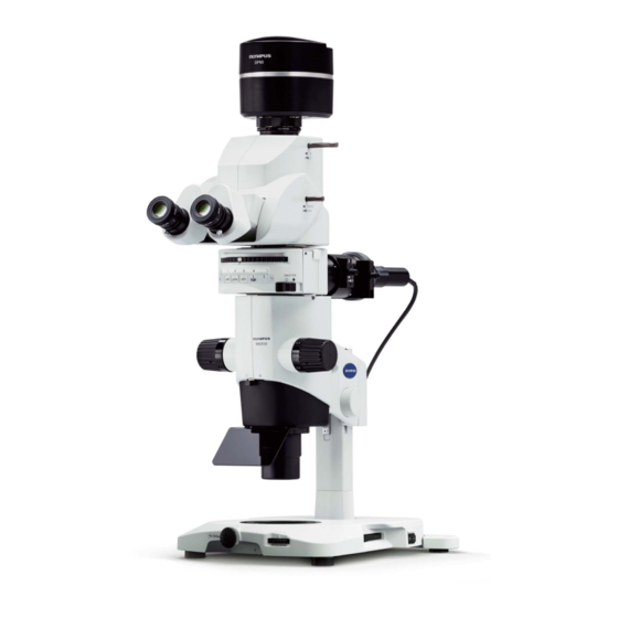
MVX10
MVX-2RE
MVX-CA2X
SZX-STAD1
SZH-STAD1
SZX-STAD2
SZ2-FO
SZH-SG
SZH-SC
This instruction manual is for the Olympus MVX Research Macro Zoom System Microscope. To
ensure the safety, obtain optimum performance and familiarize yourself fully with the use of this
attachment, we recommend you study this manual thoroughly before operating the microscope.
Retain this instruction manual in an easily accessible place near the work desk for future reference.
INSTRUCTIONS
MVX10
RESEARCH MACRO ZOOM
SYSTEM MICROSCOPE
A X 7 4 4 1
Advertisement
Table of Contents

Related Manuals for Olympus MVX10


Summary of Contents for Olympus MVX10
- Page 1 RESEARCH MACRO ZOOM SYSTEM MICROSCOPE This instruction manual is for the Olympus MVX Research Macro Zoom System Microscope. To ensure the safety, obtain optimum performance and familiarize yourself fully with the use of this attachment, we recommend you study this manual thoroughly before operating the microscope.
-
Page 3: Table Of Contents
MVX10 CONTENTS Correct assembly and adjustments are indispensable for the microscope to manifest its full performance. If you want to assemble the microscope by yourself, refer to Chapter 11, “ASSEMBLY” before other chapters. (P. 36 to P. 43) IMPORTANT — Be sure to read this section for safe use of the equipment. —... - Page 4 TRANSMITTED LIGHT OBSERVATION TROUBLESHOOTING GUIDE SPECIFICATIONS OPTICAL CHARACTERISTICS OPERATION OF OTHER MODULES 24-35 10-1 Revolving Nosepiece MVX-2RE........................24,25 10-2 Magnification Changer MVX-CA2X ........................26 10-3 BX Stage Adapter Type 1 SZX-STAD1 ....................27-29 10-4 Stage Adapter Type 1 SZH-STAD1 ........................29 10-5 BX Stage Adapter Type 2 SZX-STAD2 ....................
- Page 5 5. The power supply unit contains high-voltage parts inside. Do not attempt to disassemble it. 6. Always use the power cord provided by Olympus. If no power cord is provided, please select the power cord by referring to the section “PROPER SELECTION OF THE POWER SUPPLY CORD” at the end of this instruction manual. If the proper power cord is not used, Olympus can no longer warrant the electrical safety performance of the equipment.
- Page 6 Caution indications Caution indications are affixed at parts where special precaution is required when handling and using the microscope. Always heed the cautions. · Lamp housing [High temperature caution] Caution indication (U-LH100HG, U-LH10HGAPO) positions · Power supply unit [High voltage caution] Getting Ready }This instruction manual pertains only to the operating procedures of the Research Macro Zoom System.
-
Page 7: Operation
The used mercury burner should be disposed of as an industrial waste. If you cannot dispose of it properly, contact Olympus. 6. When disposing of the microscope. Check the regulations and rules of your local government and be sure to observe them. - Page 8 Caution If the microscope is used in a manner not specified by this manual, the safety of the user may be imperiled. In addition, the microscope may also be damaged. Always use the microscope as outlined in this instruction manual. The following symbols are used to set off text in this instruction manual.
-
Page 9: Base
}The module names listed below are typical ones that can be used with the system, and the illustration shows the system composed of modules marked {. Certain other modules are also usable even when they are not mentioned below. For these modules, refer to the latest catalogues or contact Olympus. For the modules marked *, refer to their instruction manuals. - Page 10 CONTROLS }If the microscope is not yet assembled, go to Chapter 11, “ASSEMBLY” (pages 36 to 45). The following illustration shows the systems with the modules enclosed in . For other ancillary modules, see subsequent pages. Camera Adapter Tilting Trinocular Head MVX-TV 1XC MVX-TTRS Light path selector lever (P.
- Page 11 MVX10 }Up to three fluorescence mirror units can be mounted by placing them in Fluorescence mirror units every other dovetail of the six dovetails of the MVX-RFA. U-MCFPHQ/XL # Each fluorescence mirror unit is composed of the dichroic mirror, U-MGFPHQ/XL...
- Page 12 SUMMARY OF REFLECTED FLUORESCENT LIGHT OBSERVATION PROCEDURE }For the observation procedures of other methods, see page 20. 3-1 Preparation 1. Set the shutter knob to “{” to close the shutter. (Page 14) 2. Mount the fluorescence mirror unit(s) that match the desired observation. (Page 38) 3.
- Page 13 MVX10 … ƒ † ‡ ³ ² ‰ Š }Make a photocopy of this spread and post it near the microscope for quick reference.
-
Page 14: Using The Stage Plate
OPERATION 4-1 Base Using the Stage Plate 1. When performing reflected light observation, place the stage plate with the white or black side up according to the specimen. 2. When performing transmitted light observation, use the transparent stage glass. Placing the Specimen Place the specimen on the approximate center of the stage plate (or stage glass). -
Page 15: Engaging And Disengaging The Zooming Knob Click Stop Position
MVX10 Engaging and Disengaging the (Fig. 4) Zooming Knob Click Stop Position }When the click stop knob is engaged to ON, the click stop function is engaged for each zoom ratio indicated with the zooming knob. When the knob is disengaged to OFF, the zoom magnification can be varied continuously and finely near the click groove. -
Page 16: Coaxial Fluorescence Illuminator
4-3 Coaxial Fluorescence Illuminator Selecting the Fluorescence Mirror Unit }Use the fluorescence mirror unit that is optimum for each purpose of observation. Mirror unit name Dichroic mirror Excitation filter Barrier filter Application U-MCFPHQ/XL DM450HQ BP425-445HQ BA460-510HQ ECFP U-MGFPHQ/XL DM485HQ BP460-480HQ BA495-540HQ EGFP U-MYFPHQ/XL... - Page 17 MVX10 5. IB excitation filter (wide band) U-MGFP/XL 6. IB excitation filter (wide band) U-MGFPA/XL Wavelength nm Wavelength nm...
-
Page 18: Turning The Burner On
Turning the Burner ON # The burner should be centered before the first use after it has been mounted or replaced. (see page 44) When resetting the burner hour counter, press and hold the reset button until the reading becomes “0.0”. -
Page 19: Switching The Filter Slider Knob
MVX10 Switching the Filter Slider Knob (Fig. 9) }Hold the filter slider knob @ of coaxial fluorescence illuminator and move it toward the left or right to select one of the two filter pockets or idle position. The idle position is selected when the knob is pulled to the rightmost stop position. -
Page 20: Adjusting The Interpupillar Distance
Adjusting the Interpupillar Distance (Fig. 11) # Be sure to hold the binocular assembly @ with both hands to make this adjustment. While looking through the eyepieces, hold the left and right of the bin- ocular assembly @ and adjust by opening or closing it for binocular vision until the left and right fields of view coincide completely. -
Page 21: Using The Eye Shades
MVX10 Using the Eye Shades (Fig. 13) When Wearing Eyeglasses Use with eye shades in their normal folded-down position. This will pre- vent eyeglasses from being scratched by the eyepieces. When Not Wearing Eyeglasses Extend the folded eyeshades in the direction of the arrow. This makes observation easier by preventing the inverse incidence of light from be- Fig. -
Page 22: Tv Observation And Photomicrography
TV OBSERVATION AND PHOTOMICROGRAPHY }When TV observation or photomicrography is required, use the MVX-TTRS tilting trinocular head or MVX-TLU tilting lens unit. The MVX-TV1XB/MVX-TV1XC/TV0.63XC exclusive camera adapter can be installed on this microscope. }When the MVX-TV0.63XC camera adapter is used, insufficiency of brightness in the peripheral section may sometimes be noticeable at low to intermediate zoom ratios. -
Page 23: Adjusting The Parfocality Between Observation Image And Monitor Image
MVX10 Adjusting the Parfocality Between Obser- (Figs. 17 to 19) vation Image and Monitor Image ² }The parfocality adjustment makes correction of focusing unnecessary when the observation image is switched to the image monitored with the TV camera. 1. Looking into the eyepieces, select a high zoom ratio and focus on the specimen. - Page 24 TRANSMITTED LIGHT OBSERVATION }When an SZX series transmitted illumination base is used, the microscope can be used in transmitted light brightfield/ darkfield, focal light and simplified transmitted polarized light observations. To perform these observations, rotate the mirror unit turret on the coaxial fluorescence illuminator to select the light path without fluorescence mirror unit (No.
- Page 25 Under certain conditions, performance of this unit may be adversely affected by factors other than defects. If a problem occurs, please review the following list and take remedial action as needed. If you cannot solve the problem after checking the entire list, please contact your local Olympus representative for assistance. Problem...
- Page 26 7. Lamp housing for mercury burner U-LH100HG: Lamp housing for 100 W mercury burner. U-LH100HGAPO: Apo lamp housing for 100 W mercury burner. Mercury burner: USH-103OL (OLYMPUS) or HBO103W/2 (OSRAM) Power Supply Unit: U-RFL-T 8. Operating environment · Indoor use.
- Page 27 MVX10 OPTICAL CHARACTERISTICS · Total magnification = Objective power x Zoom ratio x Eyepiece magnification Total Magnification/Actual Field Eyepiece FN · Actual field area = Objective power x Zoom ratio Eyepieces Objective WHN10X-H (Field number: 22) Total magnification Actual field (mm) MVPLAPO 0.63X...
-
Page 28: Operation Of Other Modules
OPERATION OF OTHER MODULES 10-1 Revolving Nosepiece MVX-2RE }The revolving nosepiece accepts two MVPLAPO series objectives to enable observation using a wider variety of magni- fications. The objectives can be switched quickly by simply rotating the revolving nosepiece horizontally. External View Hand guard Allen wrench (for M3 screws) - Page 29 MVX10 4. Place the nosepiece mount ³ (with its objective mounts | facing ƒ … upward) where the objective has been by aligning the screw holes. Using the Allen wrench (for M3 screws), clamp the nosepiece mount with the provided four clamping screws (M3, 6 mm long) ƒ. (Fig. 21) # As the screw holes may be hidden behind the objective mounts |, clamp the nosepiece mount while rotating it.
-
Page 30: Magnification Changer Mvx-Ca2X
10-2 Magnification Changer MVX-CA2X }When the magnification changer has been installed on the MVX-TTRS tilting trinocular head by the dealer, the observation magnification can be switched between 1X and 2X with a selector lever. Pushed-in position: 1X Pulled-out position: 2X Be sure to push in or pull out the selector lever in a position where it is stopped securely. -
Page 31: Bx Stage Adapter Type 1 Szx-Stad1
MVX10 10-3 BX Stage Adapter Type 1 SZX-STAD1 }This adapter is for installation of a U-SRG or U-SRP rotary stage on the SZX-STL large base or a SZX series illumination base. When the U-SRP rotary stage is used together with the U-FMP mechanical stage, X-Y directional movement becomes possible, which is convenient for framing during photomicrography and TV observation. - Page 32 Assembly Mechanical stage U-FMP Rotary stage Rotary stage U-SRP U-SRG Clamping screws Allen wrench Clamping screw BX stage adapter type 1 SZX-STAD1 Attaching hole Base Mounting threaded hole Mounting the Polarizer (SZX-PO) When simplified transmitted polarized light observation is required, install the polarizer on the SZX-STAD1 BX stage adapter type 1.
-
Page 33: Stage Adapter Type 1 Szh-Stad1
MVX10 Simplified Transmitted Polarized Light Observation }The SZX-AN analyzer is required. ² 1. Loosen the analyzer clamping knob @, fit the analyzer into the front of the objective ² and tighten the clamping knob (by placing it on the right side of the microscope body). -
Page 34: Bx Stage Adapter Type 2 Szx-Stad2
10-5 BX Stage Adapter Type 2 SZX-STAD2 This adapter is for installing the U-SIC4 large stage* on the SZX-STL large base**. When this stage adapter is used, the provided SZH-P400 auxiliary pillar should be used to cover the height of the stage adapter. * The U-SVL or U-SVR BX stage can also be used but the operability is degraded, and the U-SVLB and U-SVRB cannot be used due to the long stage knobs. -
Page 35: Vertical-Movement Stage Sz2-Fo
MVX10 Caution # Do not project the image of the external light source filament on the frosted surface of the frosted filter. Otherwise the frosted filter may deteriorate. # Use neutral detergent to clean the frosted filter. # In transmitted light observation at a total magnification of no more than 10X, the field of view may be obscured in the peripheral sections depending on the stage in use. - Page 36 External View & Specifications Focus adjustment knobs Stroke: Approx. 21 mm Rotation tension adjustable. Clamping screw holes Stage Load capacity: 1 kg Clamping knob Assembly 1. Attach the SZ2-FO vertical-movement stage inside the stage plate mounting hole of an applicable base by using the provided clamping screws and the Allen wrench.
-
Page 37: Gliding Stage Szh-Sg
MVX10 Adjusting the Focus (Fig. 28) Set to the middle of stroke. ² 1. Rotate one of the focus adjustment knobs @ of the SZ2-FO vertical- movement stage to set the stage in the position corresponding to the middle of the focusing stroke. -
Page 38: Cup Stage Szh-Sc
Assembly Note 1) If dirt or metallic powder is attached on the Stage plate gliding surfaces, be sure to clean them. Use the one provided Stage plate mounting with the base. ³ Note 2) When placing the gliding stage parts, be sure hole to avoid bringing the gliding surfaces in con- Gliding stage... - Page 39 MVX10 Assembly # Before assembly, remove dirt and dust from the parts and perform the operation cautiously. Specimen holder @ Fit the cut stage mount into the stage plate mounting hole of an applicable base. Specimen holder mounting hole Stage plate ²...
-
Page 40: Assembly
ASSEMBLY 11-1 Assembly Diagram The diagram below shows how to assemble the various modules. The numbers indicate the order of assembly. # When assembling the microscope, make sure that all parts are free of dust and dirt, and avoid scratching any parts or touching glass surfaces. -
Page 41: Detailed Assembly Procedures
MVX10 11-2 Detailed Assembly Procedures Mounting the Focusing Assembly (Fig. 31) 1. First loosen the focusing assembly clamping knob @ completely and, ² while holding the focusing assembly with both hands, insert the pillar ³ into the mounting hole ² from below. (Fig. 31) # Insert slowly. - Page 42 Attaching the UV Shield Plate ² (Fig. 35) Align the mounting groove ² of the UV shield plate with the two mounting pins @ on the lower part of the zoom microscope body and fit the groove with a strong force. Fig.
- Page 43 However, the barrier filter and dichroic mirror should be the Olympus products. If a commercially available product is used, Olympus cannot guarantee the safety of operation. }The arrow inscribed on the side of an Olympus barrier filter or excitation filter indicates the filter mounting orientation. Dimensional Conditions of the Optical Parts –...
- Page 44 Mounting the Coaxial Fluorescence (Fig. 38) Illuminator 1. Using the Allen screwdriver, loosen the illuminator clamping screw @. 2. Fit the round dovetail ² at the bottom of the illuminator into the mount dovetail ³ on the microscope body, and tighten the clamping screw @. }To prevent the microscope from turning over after the illuminator is ²...
- Page 45 MVX10 Mounting the Tilting Trinocular Head (Fig. 40) ² 1. Using the Allen screwdriver, loosen the clamping screw @ of the coaxial ³ fluorescence illuminator. 2. Fit the round dovetail ² on the bottom of the trinocular head into the mount dovetail ³...
- Page 46 4. Attach the + (positive) pole of a specified mercury burner | to the fixed mount on the upper side, then the - (negative) pole to the mount on the lower side. # Be sure to use the USH-103OL (OLYMPUS) or the HBO103W/2 (OSRAM) mercury burner. Fig. 43 Be careful and avoid leaving fingerprints or contaminants on the mercury burner.
- Page 47 MVX10 Attaching the Lamp Housing 1. Using the Allen screwdriver, loosen the two clamping screws @ on the lamp housing mount hole. 2. Fit the lamp housing all the way as shown in Fig. 44. 3. Tighten the clamping screws @ using the Allen screwdriver.
-
Page 48: Centration Of The Mercury (Xenon) Burner And Field Iris Diaphragm
11-3 Centration of the Mercury (Xenon) Burner and Field Iris Diaphragm }For centering of the xenon burner, use the same procedure as the mercury burner. Centering the Mercury Burner (Figs. 47 & 48) }Set the main switch to “ ” (ON) and wait until the arc image stabilizes (for 5 to 10 minutes after ignition) before proceeding to the centering. - Page 49 MVX10 Precise Centering of the Mirror }The position of the mirror has been adjusted and locked before ship- … ment. Only if you want more precise adjustment of the mirror position, proceed to the following steps immediately after the procedure in the previous paragraphs.
-
Page 50: Proper Selection Of The Power Supply Cord
If no power supply cord is provided, please select the proper power supply cord for the equipment by referring to “ Specifications ” and “ Certified Cord ” below: CAUTION: In case you use a non-approved power supply cord for Olympus products, Olympus can no longer warrant the electrical safety of the equipment. - Page 51 MVX10 Table 2 HAR Flexible Cord APPROVAL ORGANIZATIONS AND CORDAGE HARMONIZATION MARKING METHODS Alternative Marking Utilizing Printed or Embossed Harmoniza- Black-Red-Yellow Thread (Length tion Marking (May be located on Approval Organization of color section in mm) jacket or insulation of internal wir-...
- Page 52 MEMO...
- Page 53 MEMO...
- Page 54 MEMO...
- Page 56 Manufactured by Shinjuku Monolith, 2-3-1 Nishi-Shinjuku, Shinjuku-ku, Tokyo 163-0914, Japan Distributed by 48 Woerd Avenue Waltham, MA 02453, U.S.A. 8F Olympus Tower, 446 Bongeunsa-ro, Gangnam-gu, Seoul, Korea 135-509 AX7441 09...
Need help?
Do you have a question about the MVX10 and is the answer not in the manual?
Questions and answers