Advertisement
Quick Links
Advertisement

Subscribe to Our Youtube Channel
Related Manuals for Olympus MIC-D


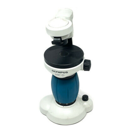
Summary of Contents for Olympus MIC-D
- Page 1 DIGITAL MICROSCOPE MIC-D REPAIR MANUAL OLYMPUS...
- Page 2 CONTENTS I N T R O D U C T I O N A .
- Page 3 INTRODUCTION 1. The purpose for this manual is to provide an outline of the MIC-D product including procedures for troubleshooting, assembly and disassembly, and adjustment. Repairs are to be performed by OLYMPUS authorized service tecnicians who have experience with optical adjustments of stereomicroscopes and who have a fundamental knowledge on the repair techniques for digital products.
-
Page 4: Outline Of Product
A. OUTLINE OF PRODUCT 1.Products (1) MIC-D is a digital microscope. MIC-D is comprized of inverted zoom optical system, with a built in digital image pickup device for CMOS. The image is displayed from the monitor of a personal computer(PC). (2) Service life 5 years 2. -
Page 5: Specifications
4. Specifications Items Specifications 1 Image pickup device 1.Maker and serial number CMOS VGA color digital camera SCIM1020, Manufactured by Olympus 2.The number of effective pixels 640(H) X 480(V) Approx. 0.3 million pixels 3.Pixel pitch 8.4μm(H) X 8.4μm(V) 2 Observation optical system 1.Magnification changer system... - Page 6 MIC-D A. OUTLINE OF PRODUCT 5. Dimensions Unit (mm) A ‑ 3...
-
Page 7: Troubleshooting
MIC-D B. TROUBLESHOOTING 1. Application does not start up. Error message is displayed. Is the error message shows "Lack of Memory? Close the other applications and expand memory. PC that is fulfilled hardware Remove error. requirement is using. Use PC that is fulfilled hardware equipment. - Page 8 MIC-D B. TROUBLESHOOTING 2. MIC-D does not recognize. Capture screen does not start up on the application. USB camera is not mounted in imaging device of system. PC is connected directly. (without HUB ) Quit HUB connection PC that is checked hardware requirement is using.
- Page 9 MIC-D B. TROUBLESHOOTING 3. Photography is not available. PC is connected directly. (without HUB) Quit HUB connection. PC that is checked hardware requirement is using. (Refer to the list) Use recommended PC. Resume function is OFF. OFF the resume function.
- Page 10 MIC-D B. TROUBLESHOOTING 4. The Light emitting Diode (LED) does not light up. Brightness adjustment knob is ON. Turn on the brightness adjustment knob. LED in D3 of CMOS board ass’y is lighting up. Refer to “Camera does not recognize” in troubleshooting.
- Page 11 MIC-D B. TROUBLESHOOTING 5. The brightness adjustment knob does not operate. LED lights up. Refer to “Illuminator LED does not light up” in troubleshooting. Zoom is the minimum. The illuminator should be the maximum already. The illuminator is the maximum (fixed).
- Page 12 MIC-D MIC-D B. TROUBLESHOOTING B. TROUBLESHOOTING 6. The light intensity adjustment does not interlock at the zooming. 6. The light intensity adjustment does not interlock at the zooming. The light intensity adjustment is possible by brightness adjustment knob. Refer to “Illuminator LED does not light up”...
-
Page 13: Connection Diagram
: You can control brightness of lighting. 2. Assembly and disassembly procedure The assembly and disassembly procedures of MIC-D will be covered in two parts as shown below. The mark(*) indicates that there are additional adjustments necessary during assembly. Head part Base part C ‑... - Page 14 MIC-D C. ASSEMBLY AND DISASSEMBLY PROCEDURES 2-1. HEAD Part (1) -1- Assemble the lens and ring to the lens frame. -2- Apply grease (Los72515) on the notch of lens frame. -3- Apply grease (Los72515) on the salient of plate. -4- Assemble the lens frame ass’y and ND filter ass’y to the head ass’y.
- Page 15 MIC-D C. ASSEMBLY AND DISASSEMBLY PROCEDURES (3) -1- Assemble shaft, cover and LED unit in the head ass’y. -2- Fix the shaft by screws (ANU3X4SA : 2 pcs and AWU3X4SA : 2 pcs). -3- Fix the LED unit by screws (3PUK2X4SA : 2 pcs) and washers.
- Page 16 MIC-D C. ASSEMBLY AND DISASSEMBLY PROCEDURES (5) -1- Apply grease(ST-1) on the shaft of head ass’y and washers. -2- Assemble lens frame, spring washer(1pc), washers and arm ass’y to head ass’y . -3- Assemble spring washers (2pcs) on the shaft.
- Page 17 MIC-D C. ASSEMBLY AND DISASSEMBLY PROCEDURES (6) -1- Fix the stage mount ass’y by screws (3PUTB2X6SA : 2 pcs). -2- Fix the cable unit by tape. -3- Apply grease (Los72515) on the lens ass’y. -4- Assemble lens ass’y on the stage mount ass’y.
- Page 18 MIC-D C. ASSEMBLY AND DISASSEMBLY PROCEDURES 2-2. Base part (1) -1- Apply grease (Los72515) on the washers. -2- Assemble washers and spring washer to the handle. Spring Washer Handle Washers(3pcs) (2) -1- Apply grease (Los72515) on the washer. -2- Assemble shaft, washer and handle ass’y on the stage mount ass’y.
- Page 19 MIC-D C. ASSEMBLY AND DISASSEMBLY PROCEDURES (3) -1- Apply grease (Los72515) on the gear. -2- Cut out a piece of polyslider by cutter. -3- Assemble gear and polyslider in the base. -4- Stick the name plate on the base. Gear...
- Page 20 MIC-D C. ASSEMBLY AND DISASSEMBLY PROCEDURES (5) -1- Apply grease (Los3340) to the side of shaft ass’y. -2- Assemble shafts in the base ass’y. -3- Fix the shaft ass’y by screws (AB3X6SA : 3 pcs). -4- Apply adhesive (TB1401C) on the screws (AB3X6SA : 3 pcs).
- Page 21 MIC-D MIC-D C. ASSEMBLY AND DISASSEMBLY PROCEDURES C. ASSEMBLY AND DISASSEMBLY PROCEDURES -4-Assemble Lens frame ass’y 1 and Lens frame ass’y 2 to base ass’y. -4-Assemble Lens frame ass’y 1 and Lens frame ass’y 2 to base ass’y. Lens frame...
- Page 22 MIC-D C. ASSEMBLY AND DISASSEMBLY PROCEDURES (7) -1- Assemble ball and spring in the base ass’y. -2- Fix the spring by screw (AHU4X4SA : 1 pc). -3- Apply adhesive (SE9176) on the screw (AHU4X4SA : 1 pc). -4- Stick cover in the base ass’y.
- Page 23 MIC-D C. ASSEMBLY AND DISASSEMBLY PROCEDURES (9) -1- Stick cover in the base ass’y. -2- Assemble lens frame and lens in the base ass’y. -3- Assemble C-MOS ass’y in the base ass’y. -4- Fix the C-MOS ass’y by screws (CUKSK3X6SA : 4 pcs) temporally.
- Page 24 MIC-D C. ASSEMBLY AND DISASSEMBLY PROCEDURES (11) -1- Remove C-MOS ass’y from base ass’y. Screws (CUKSK3X6SA : 4 pcs) -2- Assemble dustproof rubber and mildewproof in the base ass’y. -3- Fix the dustproof rubber piece by screws (ACU3X4SA : 2 pcs).
- Page 25 MIC-D C. ASSEMBLY AND DISASSEMBLY PROCEDURES (13) -1- Apply grease(ST-1) on the mounting surface of stage ass’y. -2- Assemble pins to the base ass’y. -3- Assemble cover to the base ass’y -4- Apply adhesive (SE9176) on the cover. Cover Stage ass’y Base ass’y...
- Page 26 MIC-D D.ADJUSTMENT PROCEDURE 1.Rotating force adjustment of ARM and HEAD (1)Tools -1-Tension gauge (2)Adjustment -1-Measure the rotating force of arm and head by tension gauge. -2-Check that the amount of each rotating force are in a standard. [STANDARD] ARM : 4.5-6N HEAD: 1-2N -3-In besides a standard, adjust by bolting of frame or shaft.
- Page 27 -2-USB cable -3-M01-BSW Ver.01.04 (3)Preparation -1-Install the M01-BSW to PC. -2-Connect the MIC-D with PC by USB cable. -3-Install the driver for MIC-D. -4-Chose the [Program Files]-|[OlympusMicro]-|[MIC-D]-|[EXE] folder by explorer. -5-Start the Extra.EXE(execution file for adjustment) or MIC-D.EXE in [EXE] folder.
- Page 28 -4-Focus the cross-specimen by focusing knob. -4-Focus the cross-specimen by focusing knob. -5-Set the zoom of MIC-D to lowest magnification position and Check the parfocality. -5-Set the zoom of MIC-D to lowest magnification position and Check the parfocality. highest magnification position...
- Page 29 MIC-D D.ADJUSTMENT PROCEDURE ‑9‑Fix the C‑MOS Y(CUKSK3X6SA:4pcs.) and Lightintensity adjustment board (CUKSK3X6SA:2pcs.) by screws. ‑10‑Remove the scale seal, lose the screws.(ACU3X4SA:2pcs.) scale s eal ACU3X4SA(2pcs) ‑11‑Set up the cross specimen on stage. ‑12‑Conect the USB cable with PC. ‑13‑Set up the zoom to highest magnification position.
- Page 30 (2)Tools -1-Voltage meter (3) Adjustment -1- Connect MIC-D and PC by USB cable. -2- Check that the illumination LED of MIC-D is light up. -3- Turn the volume switch clockwise until the maximum. USB cable Clockwise -4-Connect red (+) probe to the check pin 1 in the light intensity adjustment board.
- Page 31 -5-Start the Extra.EXE(execution file for adjustment) in [EXE] folder. -5-Start the Extra.EXE(execution file for adjustment) in [EXE] folder. -6-Push the [OK] button. -6-Push the [OK] button. -7-Open the default.ini for MIC-D. default.ini is chosen automatically. -7-Open the default.ini for MIC-D. default.ini is chosen automatically.
- Page 32 (3)Adjustment -1-Push the [START] button. -2-Chose the [Window]-[Maintenance Screen]. -3-Setup the MIC-D. Voltage is MAX. Zoom is MAX(255). Frosted filter is IN. Specimen is none. -4-Push the [Update RGB Display] button. -5-Each color values are displayed. Check that Green values are the 205 neighborhoods.
- Page 33 When they are not in a standard, change the CMOS ass’y. Standard: R/B,B/G = 0.8-1.2 -7-Get the color adjustment values from [Adjustment Values]-[HEX]. The Color adjustment values of this MIC-D are Blue=60 and Red=34. We stick the values on MIC-D.
- Page 34 MIC-D D.ADJUSTMENT PROCEDURE -8-Start the MIC-D.EXE and input the 6034(color adjustment values) in WBNo.. When we started the MIC-D.EXE, we need to input the WBNo.. -9-Finish the color adjustment.
- Page 35 -2-Connect the MIC-D with PC by USB cable. -3-Install the driver for MIC-D. -4-Chose the [Program Files]-[OlympusMicro]-[MIC-D]-[EXE] folder by explorer. -5-Start the Extra.EXE(execution file for adjustment) in [EXE] folder. -6-Push the [OK] button. -7-Open the default.ini for MIC-D. default.ini is chosen automatically. D-10...
- Page 36 -2-Chose the [Window]-[Maintenance Screen]. -3-Check that Cross Hairs, Connectric Circles and Field Display have check. -4-Set the zoom of MIC-D to MAX. -5-Set the cross-specimen on stage. Focus the specimen by focusing knob. -6-Adjust the center position cross for adjustment and cross of specimen.
- Page 37 MIC-D D.ADJUSTMENT PROCEDURE -7-Set the zoom of MIC-D to MIN. -8-Check the center position of cross for adjustment and cross of specimen. When optical shift is no good Loose the CUKSK3X6SA(4pcs.). Shake the CMOS ass’y and adjust the optical shift in a standard.
- Page 38 -3-M01-BSW Ver.01.04 (3)Preparation -1-Install the M01-BSW to PC. -2-Connect the MIC-D with PC by USB cable. -3-Install the driver for MIC-D. -4-Chose the [Program Files]-|[OlympusMicro]-|[MIC-D]-|[EXE] folder by explorer. -5-Start the Extra.EXE(execution file for adjustment) or MIC-D.EXE in [EXE] folder. D-13...
- Page 39 -3- Move the zoom until the memory of a specimen becomes width 12 scale and vertical 9 scale on display. 9 scales 12 scales -3- Unite and stick 132 of a zoom indicator seal on the index of MIC-D. MIC-D zoom indicator seal...
-
Page 40: List Of Jigs And Tools
MIC-D E. JIGS AND TOOLS 1. LIST OF JIGS AND TOOLS 1. LIST OF JIGS AND TOOLS 1. LIST OF JIGS AND TOOLS 1. LIST OF JIGS AND TOOLS 1. LIST OF JIGS AND TOOLS New Jigs Jig Name:Parfocality specimen for MIC-D Jig Name:Parfocality adjustment jig for MIC-D Jig NO. :MIC-DKC01 Jig NO. :MIC-DKC02 Common jigs Jigs Name Jigs NO Cross micrometer specimen AX0003 2. LIST OF PRODUCTS... -
Page 41: Lubricants And Chemicals
CHEMICALS MIC-D F. LUBRICANTS AND 1.LIST OF LUBRICANTS Lubricants Name OT NO. Los72515 OT2008 ST-1 OT3155 2.LIST OF CHEMICALS Chemicals Name OT NO. TB1401C OT1026 SE9176 OT1870 F ‑ 1... - Page 42 File Q : Are the animation files (AVI and MPEG file), which are created by the software of MIC-D, possible to play back by the other software? A : They are possible to play back by the animation software that is Windows Media Player of standard.
- Page 43 MIC-D H. EXPLANATION OF TECHNICAL TERMINOLOGY 1. CMOS (Complementary Metal Oxide semiconductor) Abbreviation of complementary metal oxide semiconductor. Pronounced see-mos, CMOS is a widely used type of semiconductor. CMOS semiconductors use both NMOS(negative polanity) and PMOS (positive polanity) circuits. Since only one of the circuit types is on at any given time, CMOS chips reqire less power than chips using just one type of transistor.
Need help?
Do you have a question about the MIC-D and is the answer not in the manual?
Questions and answers