
Related Manuals for Matrox Iris GT MIL


Summary of Contents for Matrox Iris GT MIL
- Page 1 Matrox Iris GT with MIL Installation and Technical Reference Manual no. Y11155-201-0110 June 3, 2010...
- Page 2 © Copyright Matrox Electronic Systems Ltd., 2010. All rights reserved. Limitation of Liabilities: In no event will Matrox or its suppliers be liable for any indirect, special, incidental, economic, cover or consequential damages arising out of the use of or inability to use the product, user documentation or related...
-
Page 3: Table Of Contents
Reading the state of your Matrox Iris GT ....... . . - Page 4 Determining a static IP address for Matrox Iris GT ......43 Changing the IP address of your Matrox Iris GT ......46 Using the Matrox IrisBootParams utility .
- Page 5 Installing Microsoft Visual Studio ....... . . 61 Installing Matrox Iris GT utilities ....... . . 61 Installing MIL for Microsoft Windows CE .
- Page 6 Matrox Iris GT smart camera summary ........
- Page 7 Appendix D: Using the I/O signals and controlled- current output of Matrox Iris GT ....... 107 Input and output connector .
- Page 8 Routing an auxiliary output signal from your Matrox Iris GT to a light controller ....... 139 Routing a controlled-current output from your Matrox Iris GT to a LED lighting device .
- Page 9 Utilities installed on your development computer ......161 Matrox IrisBootParams utility ........161 IrisClientUpdate utility .
- Page 10 Utilities installed on your Matrox Iris GT ....... . 180...
- Page 11 Appendix J: Troubleshooting ......239 Problems with accessing the Matrox Iris portal website ..... . 240 Your Matrox Iris GT is directly connected to your computer or a network that uses static IP addresses .
-
Page 13: Chapter 1: Before You Begin
Chapter Before you begin Chapter 1: This chapter describes the features of your Matrox Iris GT with MIL and an overview of this manual. -
Page 14: Introduction
Up to 22.5 fps Up to 15 fps Matrox Iris GT can connect to a analog RGB display device, and can communicate with other devices through the Ethernet (100/1000 BaseT), RS-232 serial port, VGA/USB port, and user-defined digital I/O signals. -
Page 15: Inspecting Your Matrox Iris Gt With Mil Package
• MIL DVD. • Matrox Iris GT Utilities DVD. ❖ Note that your Matrox Iris GT base package does not include any cables, a power supply, or a manual iris lens. For these items, refer to the Matrox Iris GT starter kit, described later in this chapter, or contact a Matrox sales representative. -
Page 16: Available Separately
16 Chapter 1: Before you begin The lens of Matrox Iris GT is a sensitive device. It should never be touched directly. Handling precautions Always cover the lens if the smart camera is not in use to reduce dust buildup. -
Page 17: Software Overview
Matrox Iris GT, find other smart cameras on your network, update the firmware, and handle licensing information. To operate Matrox Iris GT, you can use one or more Matrox Imaging software products that supports the smart camera. These are the Matrox Imaging Library (MIL) and Matrox Design Assistant. -
Page 18: Documentation Conventions
Matrox Iris GT smart camera (for example, to grab an image and communicate with connected devices) to build projects. Once the project is built, it runs on your Matrox Iris GT without relying on the resources of your development computer. Contact your Matrox sales representative for more information regarding Matrox Design Assistant. -
Page 19: Installing Mil
This section list the minimum requirements for your computer so that you can use your Matrox Iris GT with MIL, and access the Matrox Iris portal website. For specific details on how to install MIL, and other required software, refer to Chapter 6: Installing application development software. - Page 20 Note that, if these settings are set to Prompt, you will be prompted each time an ActiveX control requires downloading and is waiting to start. You must accept each prompt (click on OK) to allow Matrox Iris GT to use the ActiveX object.
-
Page 21: Manual Overview
To determine how to use the Matrox Iris GT breakout board, refer to Appendix F: The breakout board. To read the LEDs, refer to Reading the state of your Matrox Iris GT section, in Chapter 2: Powering and connecting to your Matrox Iris GT and... -
Page 22: Need Help
22 Chapter 1: Before you begin To determine how to use the Matrox Iris GT utilities, refer to Appendix H: Matrox Iris GT utilities. To determine more about the Matrox Iris portal website, refer to Appendix I: Matrox Iris portal website details. -
Page 23: Chapter 2: Powering And Connecting To Your Matrox Iris Gt
Chapter Powering and Chapter 2: connecting to your Matrox Iris GT This chapter guides you through powering your Matrox Iris GT, connecting it to another device, and reading the LEDs. -
Page 24: Powering And Connecting To Your Matrox Iris Gt
USB device (such as a keyboard or a mouse). If you have not purchased the Matrox Iris GT starter kit, refer to Matrox Iris GT connectors section, in Appendix B: Technical Reference for the pinout of your Matrox... - Page 25 I/O signals to the breakout board section, in Appendix F: The breakout board. If you have not purchased the Matrox Iris GT starter kit, use a custom cable with an M12 male 17-pin connector at one end. For more information regarding the detailed cable pin-out, refer to the Digital I/O and power connector section, in Appendix B: Technical Reference.
-
Page 26: Reading The State Of Your Matrox Iris Gt
Reading the state of your Matrox Iris GT From the moment you power up your Matrox Iris GT to the moment you power it down, at least one of the four light-emitting diodes (LEDs) at the back of Matrox Iris GT should be lit. - Page 27 Reading the state of your Matrox Iris GT The LEDs on your Matrox Iris GT are: • Power LED and User LED. The colors of these two LEDs change as your Matrox Iris GT boots. • 100/1G LED. This LED shows the connection status of your Matrox Iris GT.
- Page 28 28 Chapter 2: Powering and connecting to your Matrox Iris GT...
-
Page 29: Chapter 3: Configuring Your Matrox Iris Gt To Work On A Network
Chapter Configuring your Chapter 3: Matrox Iris GT to work on a network This chapter guides you through configuring your Matrox Iris GT to communicate with a network. -
Page 30: Network Configuration Overview
30 Chapter 3: Configuring your Matrox Iris GT to work on a network Network configuration overview This chapter details how to configure your Matrox Iris GT if it is connected to a network. If your Matrox Iris GT is directly connected to your computer, refer to Chapter 4: Configuring your Matrox Iris GT to work with your computer directly. -
Page 31: Determining Whether Your Network Uses Dhcp
Connections icon. The Network Connections dialog box opens. If you have more than one active Local area connection, or an active wireless connection, you might experience a problem with MIL connecting to your Matrox Iris GT. If this occurs, refer to the Appendix J: Troubleshooting. - Page 32 32 Chapter 3: Configuring your Matrox Iris GT to work on a network 2. Right-click on the Local Area Connection icon to display the context menu. Select the Properties command. The Local Area Connection Properties dialog box opens.
- Page 33 Matrox Iris GT to work with a network that uses DHCP section. If, however, Use the following IP address is selected, your computer uses a static IP address. Refer to the Configuring your Matrox Iris GT to work with a network that uses static IP addresses section.
-
Page 34: Configuring Your Matrox Iris Gt To Work With A Network That Uses Dhcp
Matrox Iris GT utilities, and then click on IrisBootParams. ❖ Note that the Matrox Iris GT utilities must be installed on your computer. If they are not, refer to Chapter 6: Installing application development software. The Matrox IrisBootParams utility opens. - Page 35 Configuring your Matrox Iris GT to work with a network that uses DHCP 4. Enter the MAC address of your Matrox Iris GT in the MAC Address text box. Note that the MAC address is written on a sticker attached to your Matrox Iris GT.
-
Page 36: Automatic Naming
Both the network name of your Matrox Iris GT and its MAC address are written on stickers on your Matrox Iris GT. This automatic name can be used instead of an IP address when you try to access your Matrox Iris GT. - Page 37 Matrox Iris GT utilities, and then click on IrisBootParam utility. ❖ Note that the Matrox Iris GT utilities must be installed on your computer. If they are not, refer to Chapter 6: Installing application development software.
- Page 38 38 Chapter 3: Configuring your Matrox Iris GT to work on a network The Matrox IrisBootParams utility opens. 5. Enter the MAC address of your Matrox Iris GT in the MAC Address text box. Note that the MAC address is written on a sticker attached to your Matrox Iris GT.
- Page 39 14. Reconnect the power supply to your Matrox Iris GT and wait. The Power LED and User LED of your Matrox Iris GT should both turn green at the end of the boot process. This indicates that your Matrox Iris GT is now ready to be used.
- Page 40 40 Chapter 3: Configuring your Matrox Iris GT to work on a network...
-
Page 41: Chapter 4: Configuring Your Matrox Iris Gt To Work With Your Computer Directly
Chapter Configuring your Chapter 4: Matrox Iris GT to work with your computer directly This chapter guides you through configuring your Matrox Iris GT to communicate with your computer directly. -
Page 42: Connecting Without Dhcp
(in a peer-to-peer configuration) and you want it to use a static IP address. If you have connected your Matrox Iris GT to a network that uses DHCP, refer to Chapter 3: Configuring your Matrox Iris GT to work on a network. -
Page 43: Determining A Static Ip Address For Matrox Iris Gt
IP address, you must first determine an appropriate IP address. The static IP address that you assign your Matrox Iris GT must be on the same subnet as your computer so that the two can communicate. - Page 44 44 Chapter 4: Configuring your Matrox Iris GT to work with your computer directly 2. Right-click on the Local Area Connection icon to display the context menu. Select the Properties command. The Local Area Connection Properties dialog box opens.
- Page 45 192.168.17.44 and its subnet mask is 255.255.255.0, the subnet address is 192.168.17. Select an IP address for your Matrox Iris GT that has the same subnet address as your computer and is not equal to the IP address of your computer. For the above...
-
Page 46: Changing The Ip Address Of Your Matrox Iris Gt
Changing the IP address of your Matrox Iris GT A quick way to change the IP address and subnet mask of your Matrox Iris GT is to use the Matrox IrisBootParams utility. This utility displays and allows you to change the IP address, subnet mask, and network name of your Matrox Iris GT, as well as the COM port settings. - Page 47 Changing the IP address of your Matrox Iris GT 2. Enter the MAC address of your Matrox Iris GT in the MAC Address text box. Note that the MAC address is written on a sticker attached to your Matrox Iris GT.
- Page 48 48 Chapter 4: Configuring your Matrox Iris GT to work with your computer directly...
-
Page 49: Chapter 5: Accessing Matrox Iris Gt
Chapter Accessing Matrox Chapter 5: Iris GT This chapter provides an overview of how to access your Matrox Iris GT using its web interface, FTP, file access, and telnet. -
Page 50: Accessing Matrox Iris Gt
The home page of the Matrox Iris portal website is displayed. ❖ Note that the first time that you view the Matrox Iris portal website, the License terms page might be displayed. Verify that the current date and time displayed are correct on this page. -
Page 51: Viewing Images From Your Matrox Iris Gt
❖ Note that the largest amount of bandwidth is consumed when the zoom is set to 1. Matrox Iris GT sends only what is needed to keep the amount of bandwidth used as low as possible. If the zoom is less than or greater than 1, the amount of bandwidth consumed decreases. -
Page 52: Web Access (Http)
Matrox Iris portal website and the network display published by your MIL application. All HTTP activity is saved in a file on the Matrox Iris GT flash disk. You can access the file through the Review HTTP page, accessed from the Administration... -
Page 53: File Access
File access File access Each Matrox Iris GT has a file server, which allows you to navigate the folders of your Matrox Iris GT using Microsoft Windows Explorer, create network-shared folders, and access network-shared folders. To access files on your Matrox Iris GT from your computer, enter the following in the Microsoft Windows Explorer’s location bar:... -
Page 54: Accessing Your Matrox Iris Gt From Your Computer
The easiest way to access frequently accessed Matrox Iris GT folders is to either Using Microsoft Windows Explorer map a network drive to one of the folders of your Matrox Iris GT or create a shortcut. Another way to access Matrox Iris GT folders is to use Microsoft Internet Explorer. -
Page 55: Accessing Your Computer From Your Matrox Iris Gt
Administration utility page of the Matrox Iris portal website. Telnet Each Matrox Iris GT has a telnet server. The telnet server allows you to access the command prompt of Matrox Iris GT remotely to manually start processes, run batch files, run command-line utilities, and execute commands. Error messages (for example, MIL error messages) are redirected to a telnet console, along with printf statements from applications running remotely, over the telnet session. -
Page 56: Installing The Telnet Client On Your Computer In Microsoft Windows Vista
IrisName By default, telnet is enabled. You can enable or disable your Matrox Iris GT telnet server through the Telnet / FTP server settings page of the Matrox Iris portal website. -
Page 57: File Transfer Protocol (Ftp)
FTP server activity is recorded (logged) and saved in a temporary file in \CEDisk on your Matrox Iris GT. ❖ Note that you can also access Matrox Iris GT folders with FTP by using the Browse in user files using the FTP server link, accessible from the Administration... - Page 58 58 Chapter 5: Accessing Matrox Iris GT...
-
Page 59: Chapter 6: Installing Application Development Software
Chapter Installing Chapter 6: application development software This chapter describes the installation of software used in creating, building, and transferring a MIL application for Microsoft Windows CE. -
Page 60: Introduction
This section describes the procedures necessary to install all the software required to create, build, and transfer imaging applications to your Matrox Iris GT running Microsoft Windows CE. To create a Microsoft Windows CE application on your development computer,... -
Page 61: Installing Microsoft Visual Studio
Installing software on your development computer Installing Microsoft Visual Studio To develop applications for your Matrox Iris GT, you need to install and update Microsoft Visual Studio on your development computer. Install the software in the following order: 1. Install Microsoft Visual Studio. This provides an IDE that can support Microsoft Windows CE application development. - Page 62 62 Chapter 6: Installing application development software 3. Select the Networking Services option and click on the Details button. The Networking Services dialog box is displayed. 4. Verify that Universal Plug and Play is selected. If it is not, select it. 5.
- Page 63 During installation, keep in mind the following: • If you need to change the default disk/partition and path in which to install Matrox Iris GT utilities, remember that MIL for Microsoft Windows CE and Microsoft Visual Studio should all be in the same disk/partition, although they can be located in different paths.
-
Page 64: Installing Mil For Microsoft Windows Ce
64 Chapter 6: Installing application development software Installing MIL for Microsoft Windows CE After installation of Microsoft Visual Studio and the Matrox Iris GT utilities, you need to install MIL for Microsoft Windows CE on your development computer. To install the software, insert the MIL for Microsoft Windows CE DVD into the DVD drive of your development computer. -
Page 65: Chapter 7: Creating A Microsoft Windows Ce Application For Matrox Iris Gt
Chapter Creating a Microsoft Chapter 7: Windows CE application for Matrox Iris GT This chapter describes the guidelines and procedures used in creating, building, debugging, and transferring a Microsoft Windows CE application to Matrox Iris GT. -
Page 66: Using Microsoft Visual Studio
66 Chapter 7: Creating a Microsoft Windows CE application for Matrox Iris GT Using Microsoft Visual Studio Microsoft Visual Studio provides an Integrated Development Environment (IDE) that is designed for creating applications for devices running Microsoft Windows CE (such as Matrox Iris GT). -
Page 67: Creating Your Mil Application
To debug your application, refer to the Debugging an application using Microsoft Visual Studio section. 5. Optionally, copy your application to multiple Matrox Iris GT smart cameras. For more information, refer to the Copying your application to multiple Matrox Iris GT cameras section. -
Page 68: Configuring Your Microsoft Visual Studio Project's Environment
68 Chapter 7: Creating a Microsoft Windows CE application for Matrox Iris GT Configuring your Microsoft Visual Studio project’s environment When creating a MIL application for your Matrox Iris GT, you must specify the platform and the location of the Microsoft Windows CE version of the MIL include files and library files required. -
Page 69: Creating A New Microsoft Visual Studio Project
7. Set the Show directories for drop-down list box to the Library files option. 8. Add the following paths to the list of library folders: - \Program Files\Matrox Imaging\Iris Series\Matrox Iris GT Utilities\Tools\PC\Develop - \Program Files\Matrox Imaging\Iris Series\MIL for WinCE\MIL\LIB 9. - Page 70 70 Chapter 7: Creating a Microsoft Windows CE application for Matrox Iris GT • In the Win32 Smart Device Project Wizard, select the IRISGTDISP CE6 option. No other platform should be in the Selected SDK platform list box. If creating a Visual Basic or Visual C# project using Microsoft Visual Studio 2005: •...
-
Page 71: Particularities Of Mil For Microsoft Windows Ce And Matrox Iris Gt Sdk
MIL on your development computer and your Matrox Iris GT. If you have updated your Matrox Iris GT or performed a FullRescue, the version on your Matrox Iris GT might no longer be the same as the version on your development computer. -
Page 72: Configuring The Microsoft Windows Ce Connection Manager
72 Chapter 7: Creating a Microsoft Windows CE application for Matrox Iris GT • When you create a console application using MIL for Microsoft Windows CE, use the following standard C runtime entry point: - mosMain. Can receive both ASCII and Unicode strings as arguments. The first function in your program should be mosMain(). -
Page 73: Introducing The Connection Manager Components
CONMANCLIENT is used by Microsoft Visual Studio to communicate with your Matrox Iris GT during the transfer and debugging process. CMACCEPT allows the communication between Microsoft Visual Studio and your Matrox Iris GT to occur without challenge or interruption. - Page 74 8. Click on the Transport configure button. The Configure TCP/IP transport dialog box opens. 9. Select the Use specific IP address option and enter the IP address of your Matrox Iris GT in the space provided. 10. Close all open dialog boxes by clicking on their OK button.
-
Page 75: Debugging An Application Using Microsoft Visual Studio
ActiveSync is required. Configuring your Matrox Iris GT for debugging To configure your Matrox Iris GT for debugging, set the version of Microsoft Visual Studio that is installed on your development computer. To do this, perform the following: 1. -
Page 76: Creating The Connection From Your Development Computer To
❖ Note that you must create the connection from your development computer to your Matrox Iris GT each time you need to debug or build a MIL application for your Matrox Iris GT. To create the connection from your development computer to your Matrox Iris GT, perform the following: 1. - Page 77 A welcome message appears, followed by the telnet prompt. 4. Type the following at the telnet prompt: CMACCEPT.EXE This allows your Matrox Iris GT to proceed with a debugger connection. Note that if you establish your first connection within three minutes, you can ❖...
-
Page 78: Building An Application
Matrox Iris GT, and then downloads the file to the folder on your smart camera, specified in your project’s settings. 1. If your development computer is not linked to your Matrox Iris GT, Microsoft Visual Studio will return an error. -
Page 79: Using Microsoft Visual Studio Remote Tools From Your
Microsoft Visual Studio remote tools require that CONMANCLIENT2 and CMACCEPT are running, creating a direct connection between the tools (and Microsoft Visual Studio) and your Matrox Iris GT. Without this link, the remote tools (such as the remote file viewer and remote spy) cannot function. To use... -
Page 80: Executing An Application
80 Chapter 7: Creating a Microsoft Windows CE application for Matrox Iris GT If this feature continues to cause problems, you can disable the automatic detection of Windows CE devices by performing the following: 1. Use the Tools Option menu command in Microsoft Visual Studio. The Options dialog box opens. -
Page 81: Copying Your Application To Multiple Matrox Iris Gt Cameras
To assist you in the creation of MIL applications, several examples are installed on your development computer during MIL installation. However, before these examples can be executed on your Matrox Iris GT, they must be compiled on your development computer. -
Page 82: Compiling Mil Examples
82 Chapter 7: Creating a Microsoft Windows CE application for Matrox Iris GT Compiling MIL examples Prior to executing the compiled examples on your Matrox Iris GT, you must also copy the images that are stored in the \Program files\Matrox Imaging\Iris Series\MIL for WinCE\Image folder on your development computer, to the \USERDISK\MIL\Images folder on your Matrox Iris GT. -
Page 83: Appendix A: Glossary
Appendix A: Glossary Appendix A: This appendix defines some of the specialized terms used in this manual. -
Page 84: Glossary
(and/or your Matrox Iris GT) reboots. Auto IP is used when your Matrox Iris GT is configured to get its IP address automatically from a DHCP server, and either there is no DHCP server present or the DHCP server is not responding. - Page 85 Auto IP service of a DHCP client assigns a dynamic IP address that, by default, might change each time your computer (and/or your Matrox Iris GT) reboots. A DHCP server, if used, can assign an IP address to a computer for a fixed amount of time.
- Page 86 86 Appendix A: Glossary peer-to-peer network refers to when your network is composed of only your Matrox Iris GT and your computer, and these are directly connected to each other without using another device (for example, a router). • Private IP address.
- Page 87 Glossary • Subnet. A subnet is the portion of an IP address that must be common between computers for direct communication to occur. Special hardware (routers) is required for computers on different subnets to communicate. The subnet is defined by an IP address and a subnet mask.
- Page 88 88 Appendix A: Glossary...
-
Page 89: Appendix B: Technical Reference
Appendix B: Technical Reference Appendix B: This appendix summarizes the key features of Matrox Iris GT. In addition, this appendix provides pinout descriptions for external connectors of your Matrox Iris GT. -
Page 90: Matrox Iris Gt Smart Camera Summary
External trigger to output strobe delay 7.16 CPU board The CPU board of Matrox Iris GT has the following features: • CPU: 1.6 GHz Intel® Atom®. • Volatile memory: 256 Mbytes or 512 Mbytes of DDR2 SDRAM. • Non-volatile memory: 1 Gbyte of flash disk memory. - Page 91 Matrox Iris GT smart camera summary • Digital I/Os: 5 inputs and 4 outputs (open collector). - 4 independent sink-driver auxiliary output signals, used to connect TTL or non-TTL devices (up to 24 V). Two of the four auxiliary output signals can be used as strobe signals.
-
Page 92: Software Environment
92 Appendix B: Technical Reference • Display. Your Matrox Iris GT can use a display device (a video screen), either connected to it through the VGA/USB port or through the network (using a web browser). Note that a standard USB keyboard and mouse are supported natively. To ❖... -
Page 93: Lenses
Lenses Lenses The Matrox Iris GT starter kit ships with a C-mount lens. Contact your Matrox sales representative for details. Keep the lens free of fingerprints and dust. Do not clean with an alcohol-based cleaning solution and do not spray water or cleaning fluids directly onto the lens. -
Page 94: Matrox Iris Gt Specifications
94 Appendix B: Technical Reference Matrox Iris GT specifications The following specifications detail your Matrox Iris GT. Electrical specifications GT300, GT300C, GT1200, GT1200C, GT1900, GT1900C Operating voltage and current 12V provided: 750 mA used. 24V provided: 375 mA used. I/O specifications Output signals in IND format Open collector driver. -
Page 95: Environmental Specifications
Matrox Iris GT specifications Environmental specifications GT300, GT300C, GT1200, GT1200C, GT1900, GT1900C Operating temperature 0 °C to 50 °C (32 °F to 122 °F) Ventilation requirements Natural convection. Operating humidity Up to 95% (non-condensing). Mechanical specifications GT300, GT300C, GT1200, GT1200C, GT1900, GT1900C Connectors M12 8-pin female connector for 100/1000 BaseT Ethernet. - Page 96 96 Appendix B: Technical Reference .394 OPTICAL AXIS .984 2.756 OPTICAL AXIS .234 5.95 1.240 1.006 31.50 25.55 1.299 3.862 4.331 98.10 2.856 2X 72.55 1.181 3.30 3.65 3.30 11.43 M4X0.7 - 6H 3.65 M4X0.7 - 6H 4.50 X 90°, NEAR SIDE 1.417 1.969 REF.
-
Page 97: Matrox Iris Gt Connectors
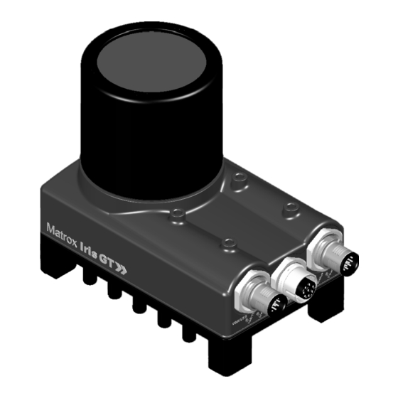
Matrox Iris GT connectors Matrox Iris GT connectors Your Matrox Iris GT has several interface connectors. These are the digital I/O and power connector, 100/1 GBase T connector, and the VGA/USB connector. The following describes the nomenclature used for signal names: AUX(USER)_OPENC_OUT6 1. -
Page 98: Digital I/O And Power Connector
The digital I/O and power connector is an M12 17-pin male connector that transmits and receives both RS-232 and digital I/O signals, controlled-current output signal, and provides power to your Matrox Iris GT. The pinout for the digital I/O and power connector is as follows:... - Page 99 Controlled-current output, designed to be connected to a LED lighting device (0-500 mA, generated using exposure timer 2). Note that if your connected LED lighting device requires 24 V, the Matrox Iris GT requires a 24 V power source. Power provided to your Matrox Iris GT. The power must be either +12 V or +24 V +/- 10%.
-
Page 100: 100/1 Gbase T Connector
100 Appendix B: Technical Reference The Matrox Iris GT starter kit includes an open-wire digital I/O and power cable. In addition, this cable can be purchased separately from Matrox (GT-CBL-PWR/3*). To build your own digital I/O and power cable, parts can be purchased from:... -
Page 101: Vga/Usb Connector
Matrox Iris GT connectors This cable can be purchased separately from Matrox (GT-CBL-ETH/5*). For an alternate source of 100/1000 BaseT cables, contact: Cable information Manufacture Phoenix Contact GmbH & Co. KG Part number: VS-M12MS-8CON-RJ45-940/5,0 Order No.: 1658781 Description: Assembled Ethernet cable, CAT 5e, shielded, 4-pair, AWG 26 stranded (7-wire), RAL 5021 (water blue), M12 8-pos. - Page 102 SHELL USB DATA USB DATA# USB VCC GROUND DRAIN WIRE SHELL This cable can be purchased separately from Matrox (GT-CBL-VGAUSB*). For an alternate source of VGA/USB cable, contact: Cable information Manufacture Phoenix Contact GmbH & Co. KG Connector: SACC-DSI-FS-8CON-L180/SCO SH Description: Sensor/actuator flush-type socket, 8-pos., M12-SPEEDCON, shielded,...
-
Page 103: Appendix C: Selecting A Lens
Appendix C: Selecting a lens Appendix C: This appendix provides information on how to select the lens best suited to your needs. -
Page 104: Introduction
104 Appendix C: Selecting a lens Introduction This appendix includes information on lens selection, an important consideration when building your application. The primary consideration during lens selection is that the focal length of the selected lens meets your application’s requirements. The focal length is the distance between the principal plane and the point where parallel light rays, bent at the principal plane, intersect the optical axis. -
Page 105: Calculating The Required Focal Length
The sensor chip type of your smart camera determines the horizontal and vertical constants required in the above-mentioned calculations. Each type of Matrox Iris GT smart camera uses a different sensor chip type. - Page 106 In this example, a lens with a focal length of 3.47 mm (horizontal) is required. If the lens shipped with your Matrox Iris GT starter kit has a focal length equal to the focal length of your calculation, you have the correct lens for your situation.
-
Page 107: Appendix D: Using The I/O Signals And Controlled- Current Output Of Matrox Iris Gt
Appendix D: Using the I/O signals Appendix D: and controlled- current output of Matrox Iris GT This appendix describes how to connect devices to the input and output connector of your Matrox Iris GT. -
Page 108: Input And Output Connector
Iris GT specifications section, in Appendix B: Technical Reference. Connecting external devices to auxiliary output signals You can send auxiliary output signals of your Matrox Iris GT to a wide variety of external devices, such as programmable logic controllers (PLC) and transistor-transistor logic (TTL) devices. - Page 109 Connecting external devices to auxiliary output signals When the auxiliary output signal is on, the circuit is grounded and the current flows from the connected device to your Matrox Iris GT; when the signal is off, the circuit is open.
-
Page 110: Connecting To An Npn-Compatible Plc Device
110 Appendix D: Using the I/O signals and controlled- current output of Matrox Iris GT Connecting to an NPN-compatible PLC device To connect your Matrox Iris GT to a NPN-compatible PLC device, connect the ground of the NPN-compatible PLC device and the ground of your Matrox Iris GT to a common ground. -
Page 111: Connecting To A Pnp-Compatible Plc Device
PNP-compatible PLC devices expect to be connected to a device that can provide power (a sourcing device) and your Matrox Iris GT is a sinking device. Therefore, connect an output signal of your Matrox Iris GT and the sourcing input to an external pull-up resistor. -
Page 112: Connecting To An Inductive Load Device
112 Appendix D: Using the I/O signals and controlled- current output of Matrox Iris GT Connecting to an inductive load device To connect your Matrox Iris GT to an inductive load device, you must first connect a high-voltage diode between them. The diode protects your Matrox Iris GT from high voltage, caused when disconnecting from the inductive load device. -
Page 113: Connecting To A Ttl Device
Connecting external devices to auxiliary output signals Connecting to a TTL device To connect your Matrox Iris GT to a TTL device, you must first connect an external pull-up resistor between them. The external pull-up resistor is needed because TTL devices expect to be connected to a device that can provide power (a sourcing device) and your Matrox Iris GT is a sinking device. -
Page 114: Connecting A Light Controller To An Auxiliary Output Signal
114 Appendix D: Using the I/O signals and controlled- current output of Matrox Iris GT Connecting a light controller to an auxiliary output signal You can control a lighting device with a light controller that is connected to auxiliary output signal 4 or 5 of your Matrox Iris GT. For example, you can control a strobe that is connected to a strobe light controller with these signals. - Page 115 Connecting external devices to auxiliary output signals Matrox Iris GT auxiliary output 4 (AUX(STB)_OPENC_OUT4) is a pulse-width modulated signal (PMW, strobe-pulse) that produces a series of pulses that have a duty cycle proportional to the intensity setting in your MIL program.
-
Page 116: Powering And Controlling A Led Lighting Device With The Matrox Iris Gt Controlled-Current Output
(ON), allowing you to control the intensity of the LED lighting device. Matrox Iris GT can provide up to 500 mA of current. MIL allows you to specify a value for the intensity, which maps to a value between 0 and 500 mA, in 256 steps. -
Page 117: Connecting External Devices To Input Signals
You can connect a wide variety of external devices to the input signals of your Matrox Iris GT, such as external triggering devices. Your Matrox Iris GT auxiliary input and trigger signals can have a 5 V, 12 V, or 24 V power source. For information regarding the electric specifications regarding the ON and OFF voltage levels, see the Electrical specifications subsection of the Matrox Iris GT specifications section, in Appendix B: Technical Reference. -
Page 118: Connecting To An External Triggering Device
118 Appendix D: Using the I/O signals and controlled- current output of Matrox Iris GT Connecting to an external triggering device To connect your Matrox Iris GT to an external triggering device, connect the ground of your Matrox Iris GT directly to the external triggering device’s ground. -
Page 119: Appendix E: Connection Modules
Appendix E: Connection modules Appendix E: This appendix details the connection modules available for use with your Matrox Iris GT. -
Page 120: Connection Modules
120 Appendix E: Connection modules Connection modules Instead of joining the wires of an open-ended cable, attached to your Matrox Iris GT, to your input and output devices, you can use a connection module. This ensures a safer, more robust, and reliable connection. -
Page 121: Vip-3/Sc/D25Sub/F Varioface Module
DB25 male terminated cable to 25 wire terminals. The VIP-3/SC/D25SUB/F VARIOFACE module passes the signals from the digital I/O and power connector of your Matrox camera to the connected third-party product(s). 19 20 21 22 23 24 25... - Page 122 Controlled-current output, designed to be connected to a LED lighting device (0-500 mA). Note that if your connected LED lighting device requires 24 V, the Matrox Iris GT requires a 24 V power source. Reserved Do not connect. Ground. This ground is reserved for use with the ground from your power supply.
-
Page 123: Dflk-D25 Sub/B Varioface Module
The DFLK-D25 SUB/B VARIOFACE module is a screw-mountable connection module that connects a DB25 male terminated cable to 25 wire terminals. The DFLK-D25 SUB/B VARIOFACE module passes the signals from the digital I/O and power connector of your Matrox camera to the connected third-party product(s). Back... - Page 124 124 Appendix E: Connection modules This module can be purchased from the following source: Cable information Manufacture: Phoenix Contact GmbH & Co. KG Connector: DFLK-D25 SUB/B Part Number: 2280323 Description: VARIOFACE panel feed-through module, for direct coupling of single signal lines of up to 2.5 mm², with D-Subminiature socket strip, 25-pos.
-
Page 125: Appendix F: The Breakout Board
Appendix F: The breakout board Appendix F: This appendix describes how to use the Matrox Iris GT breakout board. -
Page 126: Introducing The Breakout Board
126 Appendix F: The breakout board Introducing the breakout board The Matrox Iris GT breakout board allows you to test the inputs and outputs of your Matrox Iris GT, as well as initially power your smart camera. The breakout board provides a convenient way to connect the digital I/O and power cable, re-route signals, and generate triggers. - Page 127 Introducing the breakout board The following is a functional diagram of the breakout board: Push buttons (input-generating) Input selector Output router Output connector Third-party device (output-receiving)
-
Page 128: Powering Matrox Iris Gt And Connecting Its I/O Signals To The Breakout Board
The wire is now attached to the wire terminal on your breakout board. 2. If only powering your Matrox Iris GT, wrap insulating tape around all the unused wires of the Matrox Iris GT digital I/O and power cable. Otherwise, connect them to the appropriate wire terminals of the breakout board’s smart camera connector;... -
Page 129: Routing Signals To Matrox Iris Gt Input Signals
• Route a signal from a third party device to your Matrox Iris GT. • Generate a Matrox Iris GT auxiliary input or trigger signal with a push button. • Route a Matrox Iris GT auxiliary output signal to a Matrox Iris GT auxiliary input signal. -
Page 130: Routing A Signal From A Third Party Device To Your Matrox Iris Gt
130 Appendix F: The breakout board Routing a signal from a third party device to your Matrox Iris GT You can route a signal from a third-party device to your Matrox Iris GT. To do so, perform the following: 1. Connect the power and the digital I/O signals of your Matrox Iris GT to the breakout board by following the steps in the Powering Matrox Iris GT and connecting its I/O signals to the breakout board section. - Page 131 Routing signals to Matrox Iris GT input signals 3. If routing the signal to the Matrox Iris GT trigger signal, connect the ground of the breakout board (J20 of the breakout board power source connector) and the TRIG- wire terminal (J37 on the breakout board’s input connector) to the ground of the third-party device providing the trigger signal.
-
Page 132: Generating A Matrox Iris Gt Auxiliary Input Or Trigger Signal
To do so, perform the following: 1. Connect the power and the digitial I/O signals of your Matrox Iris GT to the breakout board by following the steps in the Powering Matrox Iris GT and connecting its I/O signals to the breakout board section. -
Page 133: Routing A Matrox Iris Gt Auxiliary Output Signal To A
Routing a Matrox Iris GT auxiliary output signal to a Matrox Iris GT auxiliary input signal You can route Matrox Iris GT auxiliary output signals 4 to 7 to Matrox Iris GT auxiliary input signal 0 to 3, respectively. This is primarily used for testing, allowing you to receive what was sent to the Matrox Iris GT auxiliary output signals. -
Page 134: Routing One Matrox Iris Gt Auxiliary Output Signal To The Matrox Iris Gt Trigger Signal
(TRIG_OPTO_IN0+), using the output-to-trigger bypass switch box (SW6). To do so, perform the following: 1. Connect the power and the digital I/O signals of your Matrox Iris GT to the breakout board by following the steps in the Powering Matrox Iris GT and connecting its I/O signals to the breakout board section. -
Page 135: Routing Matrox Iris Gt Outputs
• Route a controlled-current output from your Matrox Iris GT to a LED lighting device. • Route a Matrox Iris GT auxiliary output signal to a Matrox Iris GT auxiliary input signal. See the Routing a Matrox Iris GT auxiliary output signal to a Matrox Iris GT auxiliary input signal subsection of the Routing signals to Matrox Iris GT input signals section (earlier in this chapter). -
Page 136: Routing A Matrox Iris Gt Auxiliary Output Signal To A
Routing a Matrox Iris GT auxiliary output signal to a third-party device You can route an auxiliary output signal from your Matrox Iris GT to a third-party device. To do so, perform the following: 1. Connect the power, current-controlled output, and the digital I/O signals of your Matrox Iris GT to the breakout board by following the steps in the Powering Matrox Iris GT and connecting its I/O signals to the breakout board section. - Page 137 The output pull-up resistor switch box (SW7) has 4 switches, each one representing one of the four auxiliary output signals of your Matrox Iris GT. To use Matrox Iris GT auxiliary output signal 4 (AUX(STB)_OPENC_OUT4), turn on the output pull-up resistor switch 1 (SW7[1]).
- Page 138 Connecting external devices to auxiliary output signals section, in Appendix D: Using the I/O signals and controlled- current output of Matrox Iris GT. ❖ Note that when routing output signals from the smart camera connector, the...
-
Page 139: Routing An Auxiliary Output Signal From Your
(for example, a strobe controller device). To do so, perform the following: 1. Connect the power and the digital I/O signals of your Matrox Iris GT to the breakout board by following the steps in the Powering Matrox Iris GT and connecting its I/O signals to the breakout board section. -
Page 140: Routing A Controlled-Current Output From Your
Routing a controlled-current output from your Matrox Iris GT to a LED lighting device You can route the controlled-current output from your Matrox Iris GT to a LED lighting device. To do so, perform the following: 1. Connect the power, current-controlled output, and the digital I/O signals of your Matrox Iris GT to the breakout board by following the steps in the Powering Matrox Iris GT and connecting its I/O signals to the breakout board section. -
Page 141: Open-Wire Connectors Reference
Breakout board connector name Wire Connector type terminal Smart camera connector J1-J17 Connects the digital I/O and power cable of your Matrox Iris GT to the breakout board. Breakout board power source connector J19-J20 Provides power to the breakout board. Output connector J21-J30 Connects to a third-party devices so that they can receive auxiliary output signals and controlled-current output (CCS) from your Matrox Iris GT. - Page 142 142 Appendix F: The breakout board The pinout for the breakout board’s smart camera connector is as follows. Breakout board’s smart camera Digital I/O and power connector on Description connector Matrox Iris GT Wire terminal Wire color Signal name number Black TRIG_OPTO_IN0+ Opto-isolated trigger input signal, positive.
- Page 143 Matrox Iris GT (such as a Ring LED). To properly power Matrox Iris GT, J15, J16 and J17 must be connected to your smart camera. Power provided to your Matrox Iris GT. The power must be+12 V or +24 V +/- 10%.
-
Page 144: Breakout Board Power Source Connector
Note that a DC power supply is provided in the Matrox Iris GT starter kit. Alternately, you can connect an open-wire power supply to the J19 and J20 wire terminals. -
Page 145: Breakout Board's Output Connector
Matrox Iris GT, via an open-wire Each auxiliary output signal sent to a third-party device requires two wires: one to carry the signal from your Matrox Iris GT, and one to connect the external pull-up resistor to +VDC. -
Page 146: Breakout Board's Input Connector
Opto-isolated trigger signal, negative. This signal must be TRIG_OPTO_IN0- connected to the ground of the trigger-generating third party device. Opto-isolated trigger signal, positive. TRIG_OPTO_IN0+ a. Note that the negative signal is internally connected to the ground inside your Matrox Iris GT. -
Page 147: Rs-232 Serial Connector
It allows your MIL program to send and receive RS-232 messages from your Matrox Iris GT, via the J13 and J14 wire terminals of the smart camera connector To view the operating system’s console output information using a terminal... -
Page 148: Push Buttons
148 Appendix F: The breakout board Push buttons Each push button generates an input signal that is sent to your Matrox Iris GT through the breakout board’s smart camera connector. When you press a push button to create an input signal, content bounce (also called chatter) might occur. -
Page 149: Leds
TRIG+ INPUT 0 INPUT 1 INPUT 2 INPUT 3 The board reference for the LEDs is as follows:. Description Associated Matrox Iris GT Routed through the breakout signal board’s smart camera connector TRIG+ (DS1) Opto-isolated trigger signal LED. TRIG_OPTO_IN+ INPUT 0 (DS2) Opto-isolated auxiliary signal 0 (input) LED. -
Page 150: Switch Boxes
Reserved. Diagnostic switch. Set this switch to OFF unless otherwise directed by technical support. If this switch is ON, your Matrox Iris GT will not finish booting until it receives a CRLF through the serial port. Output pull-up resistor switch box... -
Page 151: Output-To-Input Bypass Switch Box
Iris GT auxiliary output signal to a Matrox Iris GT auxiliary input signal. For the Matrox Iris GT output signals to be used as input signals, the respective pin on the output pull-up resistor switch box (SW7) must be enabled. For... - Page 152 152 Appendix F: The breakout board...
-
Page 153: Appendix G: Reading The Leds
Appendix G: Reading the LEDs Appendix G: This appendix details how to read the LEDs of your Matrox Iris GT and details the potential LED error codes. -
Page 154: Reading The Leds
User Matrox Iris GT has no power. If this occurs during the power-up phase, your Matrox Iris GT is not receiving +12 V or +24 V +/- 10%. If this occurs after the power-up phase, your Matrox Iris GT is experiencing critical problems while booting. - Page 155 Your Matrox Iris GT is ready. Blinking green then red Your Matrox Iris GT is in the process of serving a memory allocation request, but the amount of free system memory has gone under 128 KBytes. For more information, refer to the Booting problems section, in Appendix J: Troubleshooting.
-
Page 156: Power Led Error Codes
There is no power. Matrox Iris GT is booting. Orange The Matrox Iris GT acquisition section is initializing or a MIL program is either waiting for a trigger or using image files from disk. Green The Matrox Iris GT acquisition section is grabbing an image. - Page 157 Boot parameters block error. 6-1-4-2-4 Boot parameters block data error. 6-1-4-3-1 Matrox Iris GT sent a maximum number of request to boot from the Ethernet without receiving an answer from a computer running the IrisOsDownloader utility. 6-1-4-3-2 Operating system downloaded through Ethernet is not valid.
- Page 158 158 Appendix G: Reading the LEDs...
-
Page 159: Appendix H: Matrox Iris Gt Utilities
Appendix H: Matrox Iris GT Appendix H: utilities This appendix describes how to use the utilities stored on your Matrox Iris GT, as well as those installed when you install the Matrox Iris GT utilities. -
Page 160: Introduction
160 Appendix H: Matrox Iris GT utilities Introduction The Matrox Iris GT utilities are a series of tools required to support all the functionality of your Matrox Iris GT. Some you must install on your development computer, using the Matrox Iris GT Utilities DVD, while others come factory-installed by default on your Matrox Iris GT (either as part of the operating system, or in the \CEDISK\Tools folder). -
Page 161: Utilities Installed On Your Development Computer
DHCP or automatic naming, ❖ Note that this utility works best if your Matrox Iris GT is directly connected to your computer. If your Matrox Iris GT is plugged into a network and there are routers between your Matrox Iris GT and your computer, this utility might not be able to find your Matrox Iris GT. - Page 162 162 Appendix H: Matrox Iris GT utilities The Matrox IrisBootParams utility opens. 2. Enter the MAC address of your Matrox Iris GT in the MAC Address text box. Note that the MAC address is written on a sticker attached to your Matrox Iris GT.
-
Page 163: Irisclientupdate Utility
• Change the COM port settings by entering the new information in the COM port parameters section. 4. Click on the Save button. This will change the settings of your Matrox Iris GT. 5. Reboot your Matrox Iris GT by unplugging it and then plugging it back in. - Page 164 The type of update performed, is dependant upon the contents of the files specified. To update one or more Matrox Iris GT on your network with this utility, perform the following: 1. On your computer, launch the IrisClientUpdate utility. To do so, from the Matrox Imaging submenu of the Windows Start menu, select Iris Series.
- Page 165 Utilities installed on your development computer 5. Before upgrading, you can examine the version information of your smart camera(s) by selecting a smart camera and clicking on the Camera firmware information button. This information includes: the camera model, the operating system’s version and QFE version (if any), the MIL version, service pack identifier, and update identifier, and the Boot ROM version.
-
Page 166: Matrox Iris Camera Finder Utility
To use this utility, perform the following: 1. On your computer, launch the Matrox Camera Finder utility. To do so, from the Matrox Imaging submenu of the Windows Start menu, select Iris Series. From the presented submenu, select Matrox Iris GT utilities, and then click on Camera Finder. -
Page 167: Matrox Iris Os Downloader Utility
3. Click on the NK.bin file, and click on the OK button. 4. Wait for the name of your Matrox Iris GT to appear in the name list. Select the target smart camera and click on the Download button. The download process begins. -
Page 168: Utilities Integrated In The Operating System Of Your Matrox Iris Gt
Utilities integrated in the operating system of your Matrox Iris GT The following is a description of the utilities that are integrated in the operating system of your Matrox Iris GT. These utilities are stored with your operating system. The following utilities are available: •... -
Page 169: Steps To Run Utilities Integrated In The Operating System Of Your Matrox Iris Gt
1. Before running either the FullRescue or IrisBackup utilities, stop any running MIL applications and share a folder on your network with your Matrox Iris GT, if one isn’t already shared. Note that, when using the FullRescue utility, this folder should contain the rescue files. -
Page 170: Autostce Utility
AUTOSTCE utility The AUTOSTCE utility launches other utilities and applications that are either essential or registered by a user in the Assignment settings page of the Matrox Iris portal website. AUTOSTCE is always executed after the operating system is initialized. AUTOSTCE will launch internal applications needed to initialize your Matrox Iris GT before launching any utilities or applications registered by a user. -
Page 171: Brflash Utility
Utilities integrated in the operating system of your Matrox Iris GT BRFlash utility The BRFlash utility updates the bootloader of your Matrox Iris GT with the specified ROM file as input. After updating the bootloader, your Matrox Iris GT must restart. -
Page 172: Connect Utility
• Domain. Specifies the domain of the user account. • MapName. Specifies the name for the connection. A folder is created with this name in the \Network folder of your Matrox Iris GT. • Resource. Specifies the network path of the resource to which to map. -
Page 173: Fpgaflash Utility
FpgaFlash utility The FpgaFlash utility updates the firmware of the acquisition section in your Matrox Iris GT, with the contents of a specified FPGA EEPROM file. After updating the acquisition section firmware, you must reboot your Matrox Iris GT for these changes to take effect. -
Page 174: Fullrescue Utility
Before using the FullRescue utility, you should backup any files added to the flash disk since the installation (or last full rescue) of your Matrox Iris GT using the IrisBackup utility. For more information, refer to the IrisBackup utility subsection, later in this appendix. - Page 175 Iris GT (boot and registry) from the rescue files. If this option is not specified, the current settings will not be overwritten. Note that, if the factory-configured settings of your Matrox Iris GT are restored, ❖ and you are in Static IP mode, you will have to use IrisBootParams to connect to your smart camera and reset the IP allocation mode back to Static IP.
- Page 176 Perform the rescue using the rescue files best associated with the version of your Matrox Iris (Matrox Iris GT with Design Assistant, Matrox Iris GT with MIL, Matrox Iris P-Series, or Matrox Iris...
-
Page 177: Irisbackup Utility
Contact Matrox Imaging technical support. IrisBackup utility The IrisBackup utility captures the state of your Matrox Iris GT and saves it as a set of files to a network-shared folder. The resulting set of files can be restored to the smart camera using the FullRescue utility, described earlier in this appendix. - Page 178 • Domain. If your computer is on a domain, enter the domain name. If your computer is not on a domain, enter the name of your computer to force Matrox Iris GT to use your local account. The user name must have a password associated with it.
-
Page 179: Osflash Utility
• Error: Cannot execute a backup while a MIL application is running. Terminate all MIL programs before using the IrisBackup utility. OSFlash utility The OSFlash utility allows you to upload an image of the Matrox Iris GT’s operating system, and overwrite (reflash) the existing copy. Syntax \>OSFlash [DEFSET] {FileName}... -
Page 180: Utilities Installed On Your Matrox Iris Gt
180 Appendix H: Matrox Iris GT utilities Utilities installed on your Matrox Iris GT The following is a description of the utilities available on your Matrox Iris GT. These utilities are stored in the \CEDisk\Tools folder. The following utilities are available: •... -
Page 181: Steps To Run Utilities Installed On Your Matrox Iris Gt
Utilities installed on your Matrox Iris GT Steps to run utilities installed on your Matrox Iris GT To run the utilities installed on your Matrox Iris GT, perform the following: 1. Open a command prompt window and type the following at the prompt: telnet IrisName A welcome message appears, followed by the telnet prompt. - Page 182 - CER64. Imports a 64-bit internet security certificate. - Request. Generates a certificate request and imports the new certificate into your Matrox Iris GT. The request is automatically sent to a Certificate Authority, downloaded, and the resulting certificate is imported. Note that this feature requires your Matrox Iris GT to have access to the internet.
-
Page 183: Cpumon Utility
The CPUMon utility monitors the changes to your CPU, RAM, and DMA of your Matrox Iris GT. It inquires the amount of memory and CPU cycles at a specified interval of time, repeating until you interrupt it, by typing q. This utility can report this information to the screen or to a file. -
Page 184: Doenddesignassistantagent Utility
It is best used for tests and debugging purposes. Note that you must manually restart the DesignAssistantAgent utility. More information on the DesignAassistantAgent utility can be found in the Utilities integrated in the operating system of your Matrox Iris GT section, earlier in this appendix. Syntax \>DoEndDesignAssistantAgent Parameters None. -
Page 185: Execlog Utility
Utilities installed on your Matrox Iris GT ExecLog utility The ExecLog utility dumps the execution log to the console or a file. Syntax \>ExecLog [Action] [Value] Parameters • Action. Specifies the action that the utility should perform. This parameter can be set to one of the following values: - Dump. -
Page 186: Filedepacker Utility
186 Appendix H: Matrox Iris GT utilities FileDepacker utility The FileDepacker utility unpacks a single file (filepack.bin) that contains multiple files. To create the packed file, refer to the FilePacker utility subsection, later in this appendix. Syntax \>FileDepacker {Source} {Destination} [Clean] Parameters •... -
Page 187: Memmon Utility
The MemMon utility monitors the changes to the global memory state of your Matrox Iris GT. It inquires the amount of memory at a specified interval of time, repeating until you interrupt it, by typing q. This utility can report this information to the screen or to a file. -
Page 188: Paramsave Utility
Matrox Iris GT registry. The values are set in memory, but not saved to the boot or permanent registry settings of your Matrox Iris GT. Note that these settings will be lost the next time you restart the operating system of your Matrox Iris GT. -
Page 189: Procmon Utility
The ProcMon utility allows you to inquire about all running applications on your Matrox Iris GT. It lists the threads and modules of each process, as well as the CPU load of each thread. It can also be used to kill a process. -
Page 190: Regdump Utility
- SAVE. Saves the registry subkey into a specified text file. To specify the text file, use the Filename parameter. - READ. Reads the specified file and configures your Matrox Iris GT. To specify the text file, use the Filename parameter. The settings are restored in memory,... - Page 191 The file name provided might be invalid. • The registry subkey selected is missing. The specified subkey could not be found in the registry of your Matrox Iris GT. Verify that the specified subkey exists and that its name was entered correctly.
-
Page 192: Remoteagent Utility
The RemoteAgent utility publishes the list of MIL displays. This list also appears as the List of displays on the View utility page of the Matrox Iris portal website. Note that the AUTOSTCE utility launches the RemoteAgent utility each time your Matrox Iris GT powers up. -
Page 193: Restart Utility
Utilities installed on your Matrox Iris GT Restart utility The Restart utility can reboot your Matrox Iris GT, restart the operating system or web server, and, if your Matrox Iris GT uses DHCP, get an IP address from the LAN’s DHCP server. Syntax \>Restart [Methodn] [IP]... -
Page 194: Tempmon Utility
DHCP is enabled. TempMon utility The TempMon utility monitors three different temperatures in Matrox Iris GT: the sensor, CPU, and ambient in-box temperature. It inquires the temperature at a specified interval of time, repeating until you interrupt it, by typing q. This utility can report these temperatures to the screen or to a file. -
Page 195: Appendix I: Matrox Iris Portal Website Details
Appendix I: Matrox Iris portal Appendix I: website details This appendix provides a description of the pages of the Matrox Iris portal website. -
Page 196: Matrox Iris Portal Website
Description Discovery Finds all Matrox Iris smart cameras on your network (including Matrox Iris GT, E-Series, and P-Series smart cameras). Clicking on the Discovery button begins the search. Once found, the list of discovered smart cameras on the network is displayed. Click on the Model URL link to go to a specific smart cameras. -
Page 197: Essential Information Page
DHCP . This can also be set using the Matrox IrisBootParams utility. Network IP allocation mode Specifies whether DHCP is used to obtain the IP address of your Matrox Iris GT. To change this information, refer to the TCP/IP settings page, which can be accessed from the Administration utility page. - Page 198 Specifies the common name shared by all computers on the network (for example, Matrox.com). To change this information, refer to the TCP/IP settings page, which can be accessed from the Administration utility page. Note that the domain can only be changed when your Matrox Iris GT uses a static IP address.
- Page 199 Web server total address space Specifies the total amount of address space given to the process of the Matrox Iris GT web server, in Kbytes. This value reflects the hardware and cannot be changed. Web server available address space Specifies the amount of free address space (that includes unreserved and uncommitted), in Kbytes.
-
Page 200: View Utility Page
OS date stamp Specifies the date when the operating system was created. OS license acceptation date Specifies the date when the license was accepted by the first visitor to the Matrox Iris portal website. OS QFE stamp Specifies the version number of the last QFE that was applied. - Page 201 Matrox Iris GT with MIL. The remote agent display allocates a digitizer because it displays a grabbed image. You cannot allocate the same digitizer twice. Therefore, if the remote agent display is selected while your Matrox Iris GT is running a MIL application that has allocated the digitizer, an error will result.
- Page 202 Button name Description Updates your Matrox Iris GT with the settings specified in the Exposure time field. - Gain. Sets the input gain with which to amplify the input signal. This allows you to optimize the amplitude of the video input signal so that the full dynamic range of the component digitizing the video is used.
-
Page 203: Assignment Settings Page
Matrox Iris folder used for synchronization Displays the name of the folder (\CEDisk) that your Matrox Iris GT checks to see if the flash disk is ready to be read. If the flash disk can successfully read the specified folder, the boot process of your Matrox Iris GT continues. - Page 204 • Start new application. Starts a specified application on your Matrox Iris GT. Field name Description Application to execute Specifies the path and all arguments needed for Matrox Iris GT to run your application. Button name Description Execute Star ts the specified application.
-
Page 205: Monitor Processes Page
Refreshes the information presented on the Monitor processes page. The monitoring process information can be displayed in several ways: • List processes. Lists all the processes currently running on Matrox Iris GT. To sort the information by column, click on a column’s title. For each process, the... - Page 206 Kills the associated process. Note that this link appears only if the process can be stopped. • List threads. Lists all the threads active on Matrox Iris GT. To sort the information by column, click on a column’s title. For each thread, the following fields and links...
-
Page 207: Review Logs
• Review execution log. The Review execution log page provides a listing of the Matrox Iris GT execution log in your web browser. The listing is a text-dump with very little formatting provided. The execution log stores power-on self test (POST) information as it occurs. This... - Page 208 Iris GT FTP log in your web browser. The listing is a text-dump with very little formatting provided. The FTP log is a text file, stored by default in the root folder of your Matrox Iris GT. Note that, to change this location, change the Default FTP server folder location in the FTP server settings section of the Telnet / FTP servers and serial console settings page page of the Matrox Iris portal website.
-
Page 209: Administration Utility Page
(3 bytes) of your Matrox Iris GT’s MAC address. Firmware monitor request wait delay (in secs) Specifies the amount of time that your Matrox Iris GT will wait for you to enter the firmware monitor before continuing to boot your Matrox Iris GT, in secs. - Page 210 Field name Description Enable boot failure detection Enables the ability to detect and count the number of times that your Matrox Iris GT fails to boot properly. When enabled, after the maximum number of unsuccessful boots allowed occurs, the boot section of your Matrox Iris GT will be reset to factory defaults. A successful boot is considered to be complete when the AutoStCE process star ts and resets the boot failure count to zero.
- Page 211 Reset DMA size Resets the MIL DMA size to its default value. The default value differs, according to the model (for example, Matrox Iris GT300 as opposed to Matrox Iris GT1200). Note that, when clicked, a warning message appears and a reboot is...
-
Page 212: Identification Settings Page
Specifies the static network name of your Matrox Iris GT. If automatic naming is disabled, the static name can be used to identify your Matrox Iris GT on the network. If automatic naming is enabled, the network name is used instead. -
Page 213: Time/Date Settings Page
The Time/date settings page allows you to manually set the date and time for your Matrox Iris GT. Note that, if SNTP or Use automatic time change for daylight savings time is enabled, you must reboot your Matrox Iris GT before changes to the date and/or time can take affect. -
Page 214: Environment Variable Settings Page
Specifies the contents of the environment variable. Button name Description Add new environment variable Adds your new environment variable to your Matrox Iris GT. • Modify environment variable. Lists all the existing environment variables, allowing you to modify or delete each one. Field name... -
Page 215: Application Error Settings Page
Reserved RAM for error dump (in Kbytes) Specifies the amount of RAM reserved for the error dump information. Folder used for storing dump files Specifies the location on your Matrox Iris GT in which to store the error dump information. Button name Description Update error dump settings Updates the error dump settings on your Matrox Iris GT. -
Page 216: Visual Studio Debugger Communication Settings Page
Specifies the minimum amount of memory to be reclaimed for the RAM file system when your Matrox Iris GT is in a critical low memory condition, in Kbytes. The default value is 0 Kbytes. To ignore this limit, set this value to 0. -
Page 217: Network Settings Page
The Network settings page includes configuring login access to your LAN, as well as securing the Matrox Iris GT web server, sharing folders via the Matrox Iris GT file server, configuring the telnet server, the FTP server, the SMTP (Simple Mail Transfer Protocol) client, and password protecting your Matrox Iris portal website. - Page 218 DHCP maximum request retry count Specifies the maximum number of times your Matrox Iris GT will try to get an IP address from the specified DHCP server. When this count is exceeded, your Matrox Iris GT will enter Auto IP mode, if enabled.
- Page 219 IP address automatically. DHCP autoconfig check interval Specifies the set amount of time after which your Matrox Iris GT will test the network to see if DHCP is now available, in secs. The default value is 385 secs.
- Page 220 Default LAN login user name Specifies your user name. Default LAN login domain Specifies the name of the login domain that your Matrox Iris GT uses to connect to a secure LAN. Default LAN login password Specifies the password for the specified user name.
- Page 221 Note that when a new shared folder is added, that folder is added to the LAN connections page, under the Modify persistent connections section. The list of connected folders can be seen in the \Network folder on your Matrox Iris GT, using HTTP, FTP, or telnet. Field name...
- Page 222 • Use Basic authentication protocol. Basic authentication uses a list of user names (or, in the case of Matrox Iris GT the single "admin" user account) and a single system password that you set for Matrox Iris GT.
- Page 223 Show HTTP request information Returns the HTTP request generated by the Web server settings page. Clicking on this link loads the HTTP request log. The HTTP request log page contains a list of all the HTTP requests answered by your Matrox Iris GT.
- Page 224 224 Appendix I: Matrox Iris portal website details Additional limitations can be added to each virtual root by setting authorization levels above public, removing access rights, and listing specific users. Field name Description New virtual root name Specifies the unique name used to identify the folder. This is the name that will be visible to users.
- Page 225 Administration utility page • Modify virtual roots. Specifies the virtual root configuration information for existing virtual roots. It also allows you to modify or delete the virtual root configuration information. Field name Description Virtual root name Specifies the unique name used to identify the folder. This is the name that will be visible to users. Virtual root location Specifies the true location of the folder.
- Page 226 Add new shared folder Adds the shared folder. To view the shared folder, refer to the Accessing Matrox Iris GT section, in Chapter 5: Accessing Matrox Iris GT. Note that the operating system must be restarted for changes to take effect.
- Page 227 Iris GT telnet server. Field name Description Enable telnet server Specifies whether telnet is enabled on your Matrox Iris GT. Telnet provides remote network terminal access from which you can easily run the Matrox Iris GT utilities. Enable authentication by telnet server Specifies whether to authenticate users accessing the telnet server.
- Page 228 (\) and not include any subfolders. Folder to store FTP log file Specifies where the FTP log file should be stored on your Matrox Iris GT. Note that the folder name should start with a back-slash (\) and not include any subfolders Maximum FTP server log files size Specifies the maximum file size of the FTP log file.
- Page 229 Specifies the number of msecs that your Matrox Iris GT should wait before trying to connect to the SNTP server and verify the time and date. Refreshing the time of your Matrox Iris GT too often is a waste of bandwidth resources.
- Page 230 • Outgoing mail client settings. Sets the simple mail transfer protocol (SMTP) server domain name used to send email and network messages between your Matrox Iris GT and the rest of your network. It also provides a way to test these settings, once enabled.
-
Page 231: Mil Licensing Settings Page
MIL date stamp Returns the date of the build. MIL build number Returns the build of MIL for Microsoft Windows CE installed on your Matrox Iris GT. MIL service/processing pack Returns the version number for the installed MIL processing pack. - Page 232 Description Select package(s) Specifies the available MIL packages. Those that are selected denote the packages you have already purchased. Your Matrox Iris GT only has access to enabled packages. To star t the purchasing process, select a package. State Specifies if the selected MIL package is licensed (Enabled or Provisional) or not (Disabled).
-
Page 233: Distributed Mil Settings Page
Description Stop/Start Starts or stops Distributed MIL on your Matrox Iris GT. The labeling of this button is dynamic. If Distributed MIL is enabled, clicking on this button will disable (stop) Distributed MIL. If, however, Distributed MIL is disabled, clicking on this button will enable (start) Distributed MIL. -
Page 234: Display Settings Page
• Display settings. Specifies the settings of the screen used by your Matrox Iris GT. Field name Description Headless device mode Enables the headless device mode and deactivates the ability for your Matrox Iris GT to use a screen. Resolution Specifies the resolution of the screen, in pixels. Pixel depth... - Page 235 Field name Description Package binary file Specifies the name of the file to update the system utility files of your Matrox Iris GT. Button name Description Browse Provides a Choose file dialog box that allows you to look for the exact location and name of the file required to update your Matrox Iris GT.
- Page 236 Matrox Iris GT. Field name Description FST file Specifies the name of the file to update the acquisition section firmware of your Matrox Iris GT. Button name Description Browse Provides a Choose file dialog box that allows you to look for the exact location and name of the file required to update your Matrox Iris GT.
-
Page 237: Rebooting And Restarting Pages
Button name Description Reboot Matrox Reboots your Matrox Iris GT. When your Matrox Iris GT reboots, it stops all processes and services. Your Matrox Iris GT Iris GT executes a power cycle to complete the reboot procedure. • Restart operating system. The Restart operating system page restarts the operating system of your Matrox Iris GT. - Page 238 238 Appendix I: Matrox Iris portal website details...
-
Page 239: Appendix J: Troubleshooting
Appendix J: Troubleshooting Appendix J: This appendix provides solutions to the most commonly-occurring problems when trying to connect to your Matrox Iris GT. -
Page 240: Problems With Accessing The Matrox Iris Portal Website
Matrox Iris GT is directly connected to your computer (in a peer-to-peer configuration) or a network that uses static IP addresses. Note that, if your Matrox Iris GT uses DHCP, refer to the Your Matrox Iris GT is connected to a network that uses DHCP subsection, later in this section. - Page 241 3. When changing from a domain into a workgroup, do not reuse shared folders. Instead create new shared folders, as necessary. 4. From your Matrox Iris GT, ping the shared folder on your development computer (\\MyComputer\IrisGTRescue) to verify that the firewall...
-
Page 242: Your Matrox Iris Gt Is Connected To A Network That Uses Dhcp
Matrox Iris GT is connected to a network that uses DHCP. Note that, if your Matrox Iris GT does not use DHCP, refer to the Your Matrox Iris GT is directly connected to your computer or a network that uses static IP addresses subsection, earlier in this section. -
Page 243: Problems With The View Utility Page
Problems with the View utility page Problems with the View utility page The following table describes typical solutions for problems that occur when using the View utility page of the Matrox Iris portal website. Item Situation Typical messages What to do... -
Page 244: Booting Problems
244 Appendix J: Troubleshooting Booting problems The following problems relate to the blink patterns of your Matrox Iris GT’s LEDs that occur while your Matrox Iris GT boots. For more information, refer to the Reading the LEDs section, in Appendix G: Reading the LEDs. - Page 245 Matrox Iris GT installation folder. Name it section, in IrisGTRescue. Appendix H: Matrox 2. From your Matrox Iris GT, ping the shared folder on Iris GT utilities. your computer (\\MyComputer\IrisGTRescue) to verify that the firewall of your computer or network router does not prevent your Matrox Iris GT to reach the selected shared rescue folder.
-
Page 246: Before Calling Technical Support
Technical Support, it is important to determine and provide some diagnostic information from your Matrox Iris GT, by performing the following: 1. Go to the Essential Information page of the Matrox Iris portal website, and save a copy of the page to your MyShared folder on your development computer. -
Page 247: Index
Index – Digital I/O and power 15 Discovery utility 197 Disk free space 199 Disk total size 198 – DMA 198 *.dll 192 *.h 60 *.lib 60 *.txt 61 Environment variable settings 214 – – 100/1000 BaseT 14 EPROM content versions 199 –... - Page 248 RAM 155 Matrox Discover utility 20 Reboot 237 Matrox Inspector 18 Remote view settings 230 – Matrox Iris portal website 36 RemoteView ActiveX 199 Restart operating system 237 Microsoft Visual Studio 66 Restart web server settings 237 Microsoft Visual Studio 2005 Revision information 231 –...
- Page 249 Connect 172 DoEndRemoteAgent 184 ExecLog 185 FileDepacker 186 FilePacker 186 FpgaFlash 173 FullRescue 174 IrisBackup 177 Matrox Iris Camera Finder 166 Matrox Iris OS Downloader 167 Matrox IrisBootParams 161 MemMon 187 ParamSave 188 ProcMon 189 RegDump 190 RemoteAgent 192 Restart 193 TempMon 194 –...
-
Page 251: Regulatory Compliance
Regulatory Compliance FCC Compliance Statement Warning Changes or modifications to these units not expressly approved by the party responsible for the compliance could void the user's authority to operate this equipment. The use of shielded cables for connections of these devices to other peripherals is required to meet the regulatory requirements. - Page 252 Bitte wenden Sie sich an dem Matrox-Website (www.matrox.com/environment/weee) für Recycling Informationen. (Italiano) Informazioni per gli utenti europei – Direttiva sui rifiuti di apparecchiature elettriche ed elettroniche (RAEE) Si prega di riferirsi al sito Web Matrox (www.matrox.com/environment/weee) per le informazioni di riciclaggio.
-
Page 253: Product Support
Software Package provided by Matrox is not covered under this limited warranty. 1.3 Matrox's limited warranty covers only those defects which arise as a result of normal use of the Matrox Hardware and does not apply to any damage which arises from: i) improper or inadequate maintenance;... - Page 254 (including theft); 1.4 If Matrox receives from the Licensee, during the applicable warranty period, notice of a defect in the Matrox Hardware, which is subsequently confirmed by Matrox, Matrox shall at its sole option, either i) repair the defect using new or refurbished parts and return the repaired Matrox Hardware within a reasonable delay;...
- Page 255 Matrox Hardware. 1.13 If the Purchaser needs to return Matrox Hardware, it must pack the Matrox Product in its original box and return it to its Matrox dealer where the Matrox Product was purchased, together with the proof of purchase. The Matrox dealer will return the Matrox Product for the Purchaser.
Need help?
Do you have a question about the Iris GT MIL and is the answer not in the manual?
Questions and answers