
Related Manuals for Matrox Iris GTX Series


Summary of Contents for Matrox Iris GTX Series
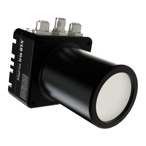
- Page 1 Matrox® Iris GTX Installation and Technical Reference Manual no. Y11537-101-0002 March 21, 2022...
- Page 2 1055 St-Regis Blvd. Dorval, Quebec, Canada H9P 2T4 Web: http://www.matrox.com/imaging Limitation of Liabilities: In no event will Matrox or its suppliers be liable for any indirect, special, incidental, economic, cover or consequential damages arising out of the use of or inability to use the product, user documentation or related...
-
Page 3: Table Of Contents
Inspecting your Matrox Iris GTX package ....... . . 10... - Page 4 Matrox Iris GTX smart camera summary ....... . . 54...
- Page 5 ........73 Matrox Imaging operating system utilities ....... . . 74 Upgrading the Matrox Imaging operating system .
-
Page 7: Chapter 1: Before You Begin
Chapter Before you begin Chapter 1: This chapter describes the features of your Matrox Iris GTX, lists the various smart camera models available, describes the software required to develop your imaging applications, outlines documentation conventions, provides an overview of this manual, and specifies where to find further support. -
Page 8: Introduction
(on-board) storage for both the operating system and additional data. 4 Gbytes of LPDDR4x SDRAM provides in-camera (on-board) volatile storage. Matrox Iris GTX is fully integrated in an IP67 enclosure, eliminating the need to separately source a sealed camera housing, while still providing easy access to the... -
Page 9: Models Available
PROFINET engine with a hardware-assisted PROFINET interface. The hardware-assisted interface supports a minimum I/O cycle time of 1 msec. Models available There are ten models available in the Matrox Iris GTX family of products. Matrox Iris GTX GTX2000 GTX2000C... -
Page 10: Inspecting Your Matrox Iris Gtx Package
• Matrox Design Assistant installation files on a USB key. Note that your Matrox Iris GTX base package does not include any cables, a power supply, nor a manual iris lens. To purchase these items, contact a Matrox sales... -
Page 11: Matrox Iris Gtx Starter Kit
• GTR-CBL-VGAUSB, a VGA/USB cable with an M12 12-pin (female) connector on one end and a HD-15 (female) connector and a USB connector on the other end. This cable connects your Matrox Iris GTX to a display device and a USB device (such as, a keyboard or mouse). -
Page 12: Available Separately
For more details about this cable, refer to VGA/USB connector subsection of the Matrox Iris GTX connectors section, in Appendix B: Technical reference. This cable is meant to connect your Matrox Iris GTX to a display device and a USB device (such as, a keyboard or mouse). -
Page 13: Third-Party Supported Devices
Matrox Iris GTX connectors section, in Appendix B: Technical reference. • Varioptic Caspian C-39N0-160-I2C or C-39N0-250-I2C lens (liquid lens). This lens is available from Varioptic and fits inside your Matrox Iris GTX’s IP lens case for IP67 compatibility. For more details about how to connect this lens, refer to Optionally connecting a liquid lens section, in Chapter 2: Powering and connecting to your Matrox Iris GTX. -
Page 14: Documentation Conventions
Chapter 1: Before you begin • Run, terminate, and re-run the project on your Matrox Iris GTX from within Matrox Design Assistant. Imaging projects can: • Grab images from your Matrox Iris GTX or use images from disk. • Analyze images using several industry-proven image analysis and measurement tools (for example, code reader and Geometric Model Finder tools). -
Page 15: Matrox Iris Gtx Safety Warnings And Key To Symbols
• There are no serviceable parts inside this product. In case of defect, contact your Matrox representative. • To maintain IP67 conformity, all unused connectors on your Matrox Iris GTX must be capped and the IP case must be screwed firmly into place. -
Page 16: Manual Overview
Matrox Iris GTX, refer to Appendix B: Technical reference. If you have a Matrox Iris GTX with Design Assistant, to use the various utilities and to recover the Matrox Imaging operating system (MIOS) on a Matrox Iris GTX, refer to Appendix C: Matrox Imaging operating system utilities and recovery. -
Page 17: Chapter 2: Powering And Connecting To Your
Chapter Powering and Chapter 2: connecting to your Matrox Iris GTX This chapter guides you through powering your Matrox Iris GTX, connecting it to another device, and reading the LEDs. -
Page 18: Powering And Connecting To Your
USB device (such as a keyboard or a mouse). • 100/1000 BaseT Ethernet connector. Provides connectivity between your Matrox Iris GTX and your computer or your network. Matrox Iris GTX can gain access to a LAN via Gbit Ethernet (GigE, 1G BaseT, or 1000BaseT), fast Ethernet (100BaseT), or twisted pair Ethernet (10BaseT). - Page 19 I/O and power connector of your Matrox Iris GTX using the provided cable. If you have purchased the Matrox Iris GTX starter kit use the open-ended digital I/O and power cable and Matrox I/O Breakout Box, included in the kit, to make the connections.
- Page 20 & hub display device Note that if you are using a Matrox VGA/USB cable, the cable has a type A USB connector. If you are not using this connector, the VGA/USB cap must remain in place for IP67 conformity.
- Page 21 Varioptic Caspian C-39N0-160-I2C or C-39N0-250-I2C lens, refer to Optionally connecting a liquid lens section, later in this chapter. Screw on the IP lens case until it is firmly in place over the lens and on the Matrox Important Iris GTX housing.
-
Page 22: Optionally Connecting A Liquid Lens
Unused Caspian lens cable Liquid lens connector Matrox Iris GTX To do so, perform the following steps: 1. Disconnect the power from your Matrox Iris GTX. 2. If in place, unscrew the IP lens case from your Matrox Iris GTX. - Page 23 7. Tuck the 3-pin connector (and its branched wire) into the folds of the longer cable. The 3-pin connector is not used. 8. Slide the IP lens case over the lens, and screw it into the Matrox Iris GTX housing, until it is firmly in place.
-
Page 24: Adding Matrox Iris Gtx To Your Network
If your network does not use DHCP, you must access and configure your Matrox Iris GTX to use a static IP address. To access Matrox Iris GTX when you don’t know its current IP address, you can physically connect to it or use the Matrox... - Page 25 Your IP address is now changed. Using the Matrox System Discovery utility for Matrox Iris GTX If you do not know your Matrox Iris GTX’s IP address, you can use the Matrox System Discovery (MtxSysDiscovery) utility to access it and change its IP address;...
-
Page 26: Connecting To Your Matrox Iris Gtx Desktop
To download and install one of these programs, perform the following: 1. For Matrox Iris GTX with Design Assistant users, go to the following web address: http:\\GTXxxxxxx:8080 Replace xxxxxx with the six digits of your smart camera’s MAC address, or if you have changed the camera’s device name, replace GTXxxxxxx with its new name. -
Page 27: Accessing Your Matrox Iris Gtx From Your Pc
Typically, Matrox Iris GTX will be listed as a computer under the Network folder. When you try to access the files on your Matrox Iris GTX, you are prompted for a user name and password. Note that these fields are case-sensitive. -
Page 28: Connecting To The Auxiliary I/O Interface
When setting up auxiliary I/O, be aware that you need to configure these pins on the software side as well. If you are using Matrox Design Assistant, refer to the Connecting to your Matrox Iris GTX as your runtime platform section of the Matrox... -
Page 29: Connecting Devices To The Auxiliary Output Signals
Connecting to the auxiliary I/O interface Connecting devices to the auxiliary output signals Matrox Iris GTX auxiliary output signals can be interfaced with input modules (with sourcing or sinking input signals) found on most programmable logic controllers (PLCs) and other devices. The auxiliary output signals can also be interfaced with inductive load devices (such as a relay or a small motor). - Page 30 Chapter 2: Powering and connecting to your Matrox Iris GTX You can also connect a single auxiliary output signal in a sourcing configuration, such that the common pin is connected to a sinking device and the dedicated pin is connected to the power supply. However, in this configuration, the other two auxiliary output signals are not available.
- Page 31 Connecting to the auxiliary I/O interface When the auxiliary output signal is attached to a device, the following can be observed: Observed voltage Signal on Signal off Connection Observed at (closed so current can flow from (open so current cannot flow from AUX_OUT to AUX_OUT_COMMON AUX_OUT pin to AUX_OUT_COMMON pin)
- Page 32 As a precaution, the auxiliary output signals are individually fuse-protected up to 50 mA. Matrox Iris GTX uses resettable fuses. The fuses protect Matrox Iris GTX if you accidentally connect their corresponding auxiliary output signal to a device that sources/sinks more current than Matrox Iris GTX can safely transmit. If more than 50 mA of current goes through your Matrox Iris GTX, the fuse will eventually trip.
- Page 33 The Matrox Iris GTX auxiliary output signals are optically isolated from the power Optically-isolated and analog intensity (dimming) control signal as well as from the Matrox Iris GTX output signals auxiliary input signals. They are not, however, optically isolated from each other as they share a common pin (AUX_OUT_COMMON).
-
Page 34: Connecting An Auxiliary Output Signal To A Sourcing Input
Chapter 2: Powering and connecting to your Matrox Iris GTX Connecting an auxiliary output signal to a sourcing input Connect a Matrox Iris GTX auxiliary output signal to a sourcing input, as shown below. Input sensing AUX_OUT INPUT Up to 24V Sourcing device –... -
Page 35: Connecting An Auxiliary Output Signal To A Sinking Input
Connecting to the auxiliary I/O interface Connecting an auxiliary output signal to a sinking input Connect a Matrox Iris GTX auxiliary output signal to a sinking input, as shown below. In this case, the pullup circuitry is used to source the current to the sinking input. - Page 36 Note that, in this configuration, you will need to connect an external pullup resistor. Since your Matrox Iris GTX auxiliary output signals can sink up to 50 mA, use the documentation of your sinking device to calculate the required resistance for your external pullup resistor (if necessary).
-
Page 37: Connecting An Auxiliary Output Signal To An Inductive Load Input
Connecting to the auxiliary I/O interface Connecting an auxiliary output signal to an inductive load input Connect a Matrox Iris GTX auxiliary output signal to an inductive load input, as shown below. An inductive load device, such as a traditional relay, requires that you use a flyback diode to protect Matrox Iris GTX from over and under-voltage, as shown below. -
Page 38: Connecting Devices To The Auxiliary Input Signals
Chapter 2: Powering and connecting to your Matrox Iris GTX Connecting devices to the auxiliary input signals Matrox Iris GTX auxiliary input signals can be interfaced with a wide variety of devices (such as proximity detectors). The Matrox Iris GTX auxiliary input signals only detect when current flows between their AUX_IN pin and AUX_IN_COMMON pin. - Page 39 In this case, select a resistor value that will not overcurrent the output device and instead provide just enough current and voltage to your Matrox Iris GTX auxiliary input signals, according to the Electrical specifications subsection in Appendix B: Technical reference.
- Page 40 Matrox Iris GTX auxiliary input signals. following subsections Note that Matrox Iris GTX auxiliary input signals are optically isolated. Ground is only shown in the following subsections for reference, in case you need to reference your return path to ground.
-
Page 41: Connecting A Sourcing Output Device To An Auxiliary Input Signal
Connecting to the auxiliary I/O interface Connecting a sourcing output device to an auxiliary input signal Connect a sourcing output device to Matrox Iris GTX auxiliary input signal, as shown below. AUX IN Sensing Circuit AUX IN_COMMON Sourcing device Matrox Iris GTX Sinking configuration Optional because the auxiliary input signals are optically isolated. -
Page 42: Connecting A Sinking Output Device To An Auxiliary Input Signal
Chapter 2: Powering and connecting to your Matrox Iris GTX Connecting a sinking output device to an auxiliary input signal Connect a sinking output device to a Matrox Iris GTX auxiliary input signal, as shown below. AUX IN_COMMON Sensing Circuit... -
Page 43: Connecting A 3-Wire Pnp Proximity Sensor To An Auxiliary Input Signal
Connecting to the auxiliary I/O interface Connecting a 3-wire PNP proximity sensor to an auxiliary input signal Connect a 3-wire PNP proximity sensor to a Matrox Iris GTX auxiliary input signal, as shown below. Brown wire Black wire AUX IN... -
Page 44: Connecting A 3-Wire Npn Proximity Sensor To An Auxiliary Input Signal
Chapter 2: Powering and connecting to your Matrox Iris GTX Connecting a 3-wire NPN proximity sensor to an auxiliary input signal Connect a 3-wire NPN proximity sensor to a Matrox Iris GTX auxiliary input signal, as shown below. AUX IN_COMMON... -
Page 45: Connecting A 2-Wire Proximity Sensor To An Auxiliary Input Signal
Connecting to the auxiliary I/O interface Connecting a 2-wire proximity sensor to an auxiliary input signal You can connect a 2-wire proximity sensor to a Matrox Iris GTX auxiliary input signal in either a sourcing or sinking configuration (that is, on a positive or negative power wire). - Page 46 Chapter 2: Powering and connecting to your Matrox Iris GTX • For the auxiliary input signal to sink the current, connect the 2-wire device to auxiliary input signal as shown below. Install the external bleeder resistor between the blue wire of the proximity sensor and the AUX_IN_COMMON pin.
-
Page 47: Connecting A Light Controller And The Analog Intensity Control Signal
Physical Camera under the Cameras item of the Platform configuration dialog, and enter a value for Intensity. See the Grab and auxiliary I/O overview section of the Matrox Iris GTX appendix in the Matrox Design Assistant help file for more information. -
Page 48: Connecting A Sourcing Light Controller (Npn Pin)
Chapter 2: Powering and connecting to your Matrox Iris GTX Connecting a sourcing light controller (NPN pin) If your lighting controller has an NPN pin (sourcing input signal), it expects to be connected in an NPN topology, whereby the connected, controlling auxiliary output signal sinks the current and the input pin sources the current. -
Page 49: Connecting A Sinking Light Controller (Pnp Pin)
To do so, connect the sinking light controller to an auxiliary output signal and the analog intensity control signal (AUX_AREF_OUT7) of Matrox Iris GTX as shown below. Note that in this configuration, the other two auxiliary output signals (AUX_OPTOIND_OUTn) from Matrox Iris GTX are not available. - Page 50 Chapter 2: Powering and connecting to your Matrox Iris GTX...
-
Page 51: Appendix A: Glossary
Appendix A: Glossary Appendix A: This appendix defines some of the specialized terms used in this manual. -
Page 52: Glossary
• Sinking. A DC circuit that provides the common reference (low) for the circuit. In the case of your Matrox Iris GTX, determining whether the connection is sinking or sourcing determines how to connect the auxiliary input common signal and auxiliary output common signal, respectively. -
Page 53: Appendix B: Technical Reference
Appendix B: Technical reference Appendix B: This appendix summarizes the hardware elements of Matrox Iris GTX. In addition, this appendix provides pinout descriptions for the external connectors of your Matrox Iris GTX. -
Page 54: Matrox Iris Gtx Smart Camera Summary
Appendix B: Technical reference Matrox Iris GTX smart camera summary Sensor board GTX2000 GTX2000C GTX5000 GTX5000C GTX8000 GTX8000C Specifications CMOS Geometry 1/2.2"-type 2/3"-type 1/1.1"-type 1/1.1"-type sensor Format Monochrome Color Monochrome Color Monochrome Color Make and ON Semiconductor - XGS model... -
Page 55: Cpu Board
Matrox Iris GTX smart camera summary CPU board The CPU board of Matrox Iris GTX has the following features: • SOC/CPU: Atom x6211E processor. • Volatile memory: 4 Gbytes of LPDDR4x SDRAM. • Non-volatile memory: 32 Gbytes of flash disk (eMMC) memory. - Page 56 (dimming) control (0-10 V translates to 0-100% illumination). - Timers.1 exposure, 1 strobe, 8 general purpose. 1 exposure timer. A 28-bit timer used to control the exposure of your Matrox ❯ Iris GTX, and allows a range of exposure time from 50 usec to 4 sec. The timer output will always set camera exposure, but can be simultaneously redirected to any auxiliary output signal.
-
Page 57: Lenses
Lenses • Display. Your Matrox Iris GTX can use a video screen connected to the VGA/USB connector to display the Matrox Iris GTX interface.The following information relates to the device that can be connected to the VGA/USB connector. - Output: RGB analog output. -
Page 58: General Care And Cleaning
The Matrox Iris GTX works with the Varioptic Caspian C-39N0-160-I2C or C-39N0-250-I2C lens (liquid lens). This electronically focus-controllable C-mount lens, fits within the IP lens case, provided with your Matrox Iris GTX. The Varioptic lens connects to the liquid lens connector inside the lens case housing of your Matrox Iris GTX. - Page 59 Maximum input current at maximum ON voltage. Note that the connected device must not limit the current to a value lower than this. e. Minimum input current at minimum ON voltage. This can be used to calculate bleeding resistor needed for 2-wire proximity sensor. Recommended > 12 V when using Matrox I/O Breakout Box.
-
Page 60: Environmental Specifications
Appendix B: Technical reference Environmental specifications • For indoor use only. • Maximum altitude: 2000 meters. • Operating temperature: 0 to 45 C (32 °F to 113 °F) • Ventilation requirements: Natural convection. • Pollution degree: 2 environment. • Over-voltage category: I •... - Page 61 Matrox Iris GTX specifications Camera heat sink [0.276] [2.402] M4x0.7 - 6H 4.00[0.157] Camera housing 7.00 61.00 O-Ring M12 Connectors [1.929] 49.00 [1.831] [3.447] [3.583] 46.50 87.55 91.00 O-Ring [2.795] 71.00 [0.276] 7.00 IP Cap [0.945] [0.236] 24.00 2x 6.00 [0.791]...
- Page 62 Appendix B: Technical reference Coin cell battery/Pile bouton • Used to maintain time and date settings of the unit’s real-time clock. Utilisée pour maintenir l'heure et la date de l’unité. • Battery voltage: 3 V. Voltage de la pile: 3 V. •...
-
Page 63: Leds On Your Matrox Iris Gtx
LEDs on your Matrox Iris GTX From the moment you power up your Matrox Iris GTX to the moment you power it down, at least one of the four light-emitting diodes (LEDs) at the back of Matrox Iris GTX should be lit. -
Page 64: Matrox Iris Gtx Connectors
Red/Orange blink The image sensor is not detected. Orange Matrox Iris GTX is in an idle state. A MIL or Matrox Design Assistant application could also be waiting for a trigger. Green Matrox Iris GTX image acquisition is in progress. -
Page 65: Digital I/O And Power Connector
Matrox Iris GTX connectors Matrox Iris GTX connectors Your Matrox Iris GTX has several interface connectors. These are the Digital I/O and power connector, the VGA/USB connector, the 100/1000 BaseT Ethernet connector, and the liquid lens connector. Digital I/O and... - Page 66 Opto-isolated industrial auxiliary signal 2 (output). Supported function: user-bit 2 (output 3 of 3). Green + VDC Positive pin of the power provided to your Matrox Iris GTX. This pin must be connected to a + 24 V +/- 10% power supply. Pink AUX(TRIG)_OPTOIND_IN3 AUX IO3 Opto-isolated industrial auxiliary signal 3 (input).
- Page 67 Supported function: user-bit 0 (output 1 of 3). Gray-Pink - VDC Negative pin of the power provided to your Matrox Iris GTX. This pin must be connected to the electrical return path of the + 24 V +/- 10% power supply connected to the +VDC pin.
-
Page 68: 100/1000 Baset Ethernet Connector
Appendix B: Technical reference 100/1000 BaseT Ethernet connector The 100/1000 BaseT Ethernet connector is an M12 (female) 8-pin X-coded connector that provides communication capabilities at 10 Mbit/sec, 100 Mbit/sec, or 1 Gbit/sec (1000 Mbit/sec). For PROFINET communication, this interface provides a hardware-assisted PROFINET interface, which supports a minimum cycle time of 1 msec. - Page 69 85 Hz The pinout for the VGA/USB connector is as follows: Pin number Signal name Description USB PWR 5 V supplied from your Matrox Iris GTX to the USB peripherals. USB_DATA_P USB data +. USB_DATA_N USB data -. USB_REF USB reference.
- Page 70 GND 11 8 GND VGA Reference VGA Reference DRAIN WIRE SHELL SHELL USB DATA USB DATA# USB VCC USB Reference DRAIN WIRE SHELL SHELL This cable can be purchased as part of the starter kit, or separately from Matrox (GTR-CBL-VGAUSB).
-
Page 71: Liquid Lens Connector
C-39N0-250-I2C lens. The secondary, 3-pin male connector, from the Varioptic lens is not used. This connector is located inside the lens cap housing of your Matrox Iris GTX. The pinout for the liquid lens connector is as follows: Pin number... - Page 72 Appendix B: Technical reference...
-
Page 73: Appendix C: Matrox Imaging Operating System
Appendix C: Matrox Imaging Appendix C: operating system utilities and recovery This appendix describes the utilities found on your Matrox Iris GTX and provides instructions on how to recover the Matrox Imaging operating system (MIOS) that comes with Matrox Iris GTX. -
Page 74: Matrox Imaging Operating System Utilities
• Bonjour browser. This is a link to the Internet that leads to the Bonjour browser website. Bonjour browser is a program that lists all the services on your subnet. This provides a way to find the IP address of any Matrox Iris GTX on the subnet. -
Page 75: Upgrading The Matrox Imaging Operating System
3. Once the MIOS ISO file has been selected, click on the Update button in the Update dialog and your update will begin. The ISO file will be copied to Matrox Iris GTX; then, the camera will power cycle. Upon power cycling, the camera is upgraded. -
Page 76: Restoring The Matrox Imaging Operating System
Iris GTX, or you can restore it from a USB key with a factory default MIOS ISO. Restoring the factory default MIOS The factory default version of the MIOS ISO is stored on the Matrox Iris GTX recovery partition. To recover the factory default version, perform the following: 1. -
Page 77: Acquiring And Restoring Mios From A Usb Key
Restoring the Matrox Imaging operating system to factory defaults 3. Near the end of the BIOS boot process, after the BIOS logo appears, a monochrome screen presents two options: load the current OS or load the recovery ISO from the Recovery MIOS partition. Use your keyboard to select the latter. -
Page 78: Updating The Matrox Iris Gtx Bios
78 Appendix C: Matrox Imaging operating system utilities and recovery 4. After selecting to load the MIOS from the recovery partition, a disk check will be performed. Once the check is complete, the Matrox Imaging OS - Recovery page is presented. - Page 79 Warning! This will replace the contents of your Matrox Iris GTX’s storage drive. 6. After installation, the unit will reboot. Select OK when prompted to reboot, and Matrox Iris GTX will reboot loaded with the factory default MIOS.
- Page 80 To safely copy your factory default MIOS ISO and use it to install a new operating system on multiple Matrox Iris GTX units, you should burn the factory default MIOS ISO to a blank USB key with a capacity of 4 Gbytes, or more. To do so: 1.
- Page 81 Restoring the Matrox Imaging operating system to factory defaults 4. Click on Select to navigate to the location of the MIOS file to burn to the USB key, and select the USB key to use from the Device drop-down menu.
- Page 82 82 Appendix C: Matrox Imaging operating system utilities and recovery 9. Another pop-up will appear asking you in which mode to write your ISO image. Select Write in DD Image mode. 10. Once this process is complete, double-click on the Safely Remove icon in your...
- Page 83 Matrox Iris GTX, as described in Chapter 2: Powering and connecting to your Matrox Iris GTX. 1. With your bootable USB key connected to your Matrox Iris GTX, reboot your Matrox Iris GTX. 2. When the BIOS logo appears, press the ESC key to open the front page of the BIOS menu.
- Page 84 4. From the BIOS boot device menu, select the EFI USB Device option from the EFI Boot Devices list. Matrox Iris GTX will then boot from the USB key. 5. After selecting to boot from the USB key, the Matrox Imaging OS - Recovery page is presented.
- Page 85 Warning! This will replace the contents of your Matrox Iris GTX’s storage drive. 7. After installation, a prompt warns that the system will shut down and that you will need to remove the external boot device before booting up again. Click on...
- Page 86 MIOS ISO. This backup is stored in the recovery partition of Matrox Iris GTX. This MIOS ISO cannot be mounted onto a USB key; it can only be stored on one.
- Page 87 To deploy the backup MIOS ISO, perform the following: 1. Reboot your Matrox Iris GTX. 2. Near the end of the BIOS boot process, after the BIOS logo appears, a monochrome screen presents you with three options, instead of two: load the current MIOS, load the recovery ISO, or load the backup ISO.
- Page 88 MIOS ISO. To deploy the backup MIOS ISO to multiple units, perform the following: 1. Locate the backup MIOS ISO and copy it to a known location on the Matrox Iris GTX unit that you will be restoring.
- Page 89 Making a backup MIOS and deploying it on multiple units 4. Near the end of the BIOS boot process, after the BIOS logo appears, a monochrome screen presents three options: load the current MIOS, load the Recovery ISO, or load the backup ISO. Use your keyboard to select the latter.
- Page 90 90 Appendix C: Matrox Imaging operating system utilities and recovery 5. After selecting to boot from the backup MISO ISO, the Matrox Imaging OS - Backup page is presented. Select Install to System Disk. After installation completes, the unit will reboot and the backed up version of the...
- Page 91 To find a VCN client or Putty, follow the instructions in the Matrox Imaging operating system utilities section, earlier in this appendix. 2. If you are connecting with a VNC client, once the Matrox Iris GTX desktop is displayed, open a terminal window by clicking on the Activities menu command and then the Terminal icon.
- Page 92 IrisGTX_100002.bin). The BIOS update starts after a 10-second delay. Once the BIOS update begins, information will appear on your local display. 5. When the BIOS update completes, you will be prompted to reboot Matrox Iris GTX. Changes made will not take effect until you reboot.
-
Page 93: Appendix D: Listing Of Matrox Iris Gtx Smart Cameras
Appendix D: Listing of Matrox Appendix D: Iris GTX smart cameras This appendix lists the key feature changes to the Matrox Iris GTX smart cameras. -
Page 94: Key Feature Changes
Key feature changes Part number Version Description GTX2000C, GTX5000C, First shipping version of Matrox Iris GTX color models running the Matrox Imaging GTX8000C, GTX12000C, operating system (64-bit) with Matrox Design Assistant IDE. GTX16000C GTX2000, GTX5000, GTX8000, First shipping version of Matrox Iris GTX monochrome models running the Matrox Imaging GTX12000, GTX16000 operating system (64-bit) with Matrox Design Assistant IDE. -
Page 95: Index
– User 62 – 100/1000 BaseT 11 Lens, physical 11 Configuring 24 – Liquid lens 13 LED 62 Matrox I/O Breakout Box 12 Cable – 100/1000 BaseT 11 Digital I/O and power 11 – Connecting 19 Network path 27 –... - Page 96 VGA/USB cable 12 – connector 11 VNC 26 VNC See Connecting remotely website, support 16...
-
Page 97: Regulatory Compliance
Regulatory Compliance FCC Compliance Statement Warning Changes or modifications to these units not expressly approved by the party responsible for the compliance could void the user's authority to operate this equipment. The use of shielded cables for connections of these devices to other peripherals is required to meet the regulatory requirements. - Page 98 (Italiano) Informazioni per gli utenti europei – Direttiva sui rifiuti di apparecchiature elettriche ed elettroniche (RAEE) Si prega di riferirsi al sito Web Matrox (www.matrox.com/environment/weee) per le informazioni di riciclaggio. Caution: Coin cell bettery replacement Risk of explosion if battery is replaced with an incorrect type. Dispose of used batteries according to local...
-
Page 99: Limited Warranty
Limited Warranty Refer to the warranty statement that came with your product.
Need help?
Do you have a question about the Iris GTX Series and is the answer not in the manual?
Questions and answers