
Related Manuals for Matrox Iris E Series


Summary of Contents for Matrox Iris E Series
- Page 1 Matrox Iris E-Series with Design Assistant Installation and Technical Reference Manual no. Y11015-201-0102 September 10, 2007...
- Page 2 © Copyright Matrox Electronic Systems Ltd., 2007. All rights reserved. Limitation of Liabilities: In no event will Matrox or its suppliers be liable for any indirect, special, incidental, economic, cover or consequential damages arising out of the use of or inability to use the product, user documentation or related...
-
Page 3: Table Of Contents
Introduction ............10 Matrox Iris E-Series remote head........12 Matrox Design Assistant . - Page 4 Your Matrox Iris E-Series with DHCP ........
-
Page 5: Chapter 3 : C O N N E C T I N G T O Y O U R M A T R O X I R I S E - S E R I E
A p p e n d i x A : T e c h n i c a l R e f e r e n c e ......6 9 Matrox Iris E-Series smart camera summary ....... 70 Sensor board . - Page 6 Matrox Iris E-Series specifications ........
- Page 7 A p p e n d i x F : L E D E r r o r C o d e s ......9 7 Power LED error codes .
- Page 9 C h a p t e r Before you begin C h a p t e r 1 : T h i s c h a p t e r b r i e f l y d e s c r i b e s t h e f e a t u r e s o f M a t r o x I r i s E - S e r i e s a s w e l l a s t h e s o f t w a r e t h a t c a n b e u s e d w i t h t h e s m a r t c a m e r a .
-
Page 10: Chapter 1 : B E F O R E Y O U B E G I N
C h a p t e r 1 : B e f o r e y o u b e g i n I n t r o d u c t i o n The Matrox Iris E-Series is a family of powerful smart cameras with an intuitive flowchart-based integrated development environment (IDE) called Matrox Design Assistant. - Page 11 I n t r o d u c t i o n Matrox Iris E-Series can connect to any device through an ethernet network interface, RS-232 serial interface, and user-defined digital I/O signals. Matrox Iris E-Series 128 MB SDRAM Intel...
-
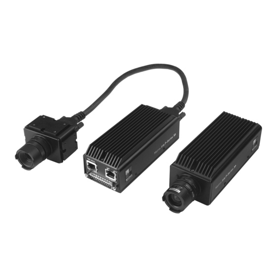
Page 12: Matrox Iris E-Series Remote Head
M a t r o x I r i s E - S e r i e s r e m o t e h e a d Every member of the Matrox Iris E-Series family is available in a uni-body or two-piece design. -
Page 13: Matrox Design Assistant
Matrox Iris E-Series. • Design and layout a web page (operator view) to receive operator input and to display your project's output. • Run, terminate, and re-run the project on your Matrox Iris E-Series from within Matrox Design Assistant. Imaging projects can: •... -
Page 14: Inspecting Your Matrox Iris E-Series Package
If you purchased Matrox Iris E-Series with a remote head, your package should include the following: • Matrox Iris E-Series body. Note that the body is separate from the remote head. • Matrox Design Assistant DVD. • A quick start guide. -
Page 15: Matrox Iris E-Series Power Supply And Cable Kit
H a n d l i n g p r e c a u t i o n s The lens of Matrox Iris E-Series is a sensitive device. It should never be touched directly. Always cover the lens if the smart camera is not in use to reduce dust buildup. -
Page 16: Overview
3. Complete the hardware setup, as described in Chapter 3: Connecting to your Matrox Iris E-Series. 4. If your network does not rely on DHCP, you must connect to your Matrox Iris E-Series and change its IP address, as described in Chapter 4: Your Matrox Iris E-Series without DHCP. - Page 17 Appendix A: Technical Reference. To learn more regarding the life expectancy of your Matrox Iris E-Series flash disk, refer to Appendix B: Flash disk life expectancy. To select a lens, refer to Appendix C: Selecting a lens.
- Page 18 C h a p t e r 1 : B e f o r e y o u b e g i n...
- Page 19 C h a p t e r Installing Matrox C h a p t e r 2 : Design Assistant T h i s c h a p t e r d e s c r i b e s t h e i n s t a l l a t i o n o f M a t r o x D e s i g n...
-
Page 20: Chapter 2 : I N S T A L L I N G M A T R O X D E S I G N A S S I S T A N
• Microsoft Windows XP with service pack 2 or above, or Microsoft Vista. • A DVD reader. • Up to 310 Mbytes of free hard disk space to install Matrox Design Assistant. Note that less space might be required if Microsoft .NET 1.0 and 2.0 Framework files are already installed on your system. -
Page 21: Matrox Iris Portal Website Requirements
For the latest information on Matrox Design Assistant, refer to the Readme.txt file in the Matrox Design Assistant folder. 1. You are required to follow the Quick Start Guide to access and legally use the Matrox and other related software licenses. In the event you use the Matrox and other related... -
Page 22: Matrox Design Assistant Licensing
MIL license settings web page on your Matrox Iris E-Series. The MIL licensing settings web page, accessible from the Assignment settings page of the Matrox Iris portal website, provides a list of available packages and whether they have been purchased (enabled) or not (disabled). - Page 23 M a t r o x D e s i g n A s s i s t a n t l i c e n s i n g 6. Copy the lock code to an email and send it to your local Matrox sales representative.
- Page 24 C h a p t e r 2 : I n s t a l l i n g M a t r o x D e s i g n A s s i s t a n t...
- Page 25 C h a p t e r 3 : Matrox Iris E-Series T h i s c h a p t e r o u t l i n e s t h e p r o c e d u r e s i n v o l v e d i n t u r n i n g y o u r M a t r o x I r i s E - S e r i e s o n a n d o f f a n d p h y s i c a l l y c o n n e c t i n g y o u r M a t r o x I r i s E - S e r i e s .
-
Page 26: Connecting To Matrox Iris E-Series
LAN’s ethernet jack with the appropriate type of cable. Matrox Iris E-Series can gain access to a LAN via Fast ethernet (100BaseT) or Twisted Pair ethernet (10BaseT). If you plan to use Fast ethernet, use an Unshielded Twisted Pair Category 5 (UTP5) cable. - Page 27 To view serial communication messages, use Microsoft HyperTerminal, or some other serial client, on your computer. Note that your serial client program must be running when your Matrox Iris E-Series powers up to see the majority of the messages generated.
- Page 28 C h a p t e r 3 : C o n n e c t i n g t o y o u r M a t r o x I r i s E - S e r i e s If you are using a Matrox Iris E-Series remote head, the front panel of your Matrox Iris E-Series has the following interface: •...
-
Page 29: Power Up Your Matrox Iris E-Series
P o w e r u p y o u r M a t r o x I r i s E - S e r i e s After connecting the power cable to your Matrox Iris E-Series, a series of steps are executed to start Microsoft Windows CE .NET. -
Page 30: Leds
C h a p t e r 3 : C o n n e c t i n g t o y o u r M a t r o x I r i s E - S e r i e s L E D s From the moment you power up your Matrox Iris E-Series to the moment you power it down, at least one of the four light-emitting diodes (LEDs) on the back of Matrox Iris E-Series should be lit. - Page 31 M a t r o x I r i s E - S e r i e s i s r e a d y . • Link. This LED shows the connection status of your Matrox Iris E-Series. L E D D e s c r i p t i o n M a t r o x I r i s E - S e r i e s i s c o n n e c t e d t o t h e n e t w o r k .
-
Page 32: Your Matrox Iris E-Series With Dhcp
Y o u r M a t r o x I r i s E - S e r i e s w i t h D H C P Once your Matrox Iris E-Series is connected to a LAN with DHCP, you should be able to browse to Matrox Iris E-Series. When both the PWR and USER LEDs are green, your Matrox Iris E-Series has joined the network. -
Page 33: Matrox Iris Portal Website
M a t r o x I r i s p o r t a l w e b s i t e Once your Matrox Iris E-Series has joined your network, you can browse to the Matrox Iris portal website, which exists on yourMatrox Iris E-Series. The Matrox... -
Page 34: Enabling Activex Components
E n a b l i n g A c t i v e X c o m p o n e n t s The Matrox Iris portal website and the Matrox Discovery utility use ActiveX components. ActiveX must be enabled on your computer. In addition, the Matrox Iris portal website must be listed in Microsoft Internet Explorer as a trusted site. - Page 35 8. Then, click on the Close button to close the Trusted sites dialog box. Click on the OK button to close the Security tab. 1. This setting is required by the Matrox Discovery utility on the Matrox Iris portal web- site, but not the Matrox Discovery utility on your computer.
-
Page 36: Accessing The Portal Website
Clicking on the phrase Matrox Iris configuration portal home, at the top of any page, will reload the Matrox Iris portal website home page. For a field-by-field description of each page, refer to Appendix E: Matrox Iris portal website details. -
Page 37: Powering Down Matrox Iris E-Series
Once the above-mentioned limitations are assured, you can power down your Matrox Iris E-Series by unplugging its power cable. ❖ Note that on the home page of the Matrox Iris portal website, you can automatically reboot your Matrox Iris E-Series. - Page 38 C h a p t e r 3 : C o n n e c t i n g t o y o u r M a t r o x I r i s E - S e r i e s...
- Page 39 C h a p t e r Your Matrox Iris C h a p t e r 4 : E-Series without DHCP T h i s c h a p t e r o u t l i n e s t h e p r o c e d u r e s i n v o l v e d i n f i n d i n g a n d u s i n g y o u r M a t r o x I r i s E - S e r i e s o n y o u r n e t w o r k w i t h o u t D H C P o r i n a p e e r - t o - p e e r c o n f i g u r a t i o n .
-
Page 40: Chapter 4 : Y O U R M A T R O X I R I S E - S E R I E S W I T H O U T D H C
IP remains enabled, Matrox Iris E-Series will automatically use the IP address assigned to it by DHCP. Your Matrox Iris E-Series checks every 300 secs to see if a DHCP server is available. If your Matrox Iris E-Series is moved from a LAN with DHCP to a LAN without DHCP, by default, Matrox Iris E-Series will automatically assign itself a private IP address with Auto IP. - Page 41 Use the Matrox Discovery utility to find your Matrox Iris E-Series smart camera and create this association. The following diagram shows the tasks required to configure both your computer and your Matrox Iris E-Series. Each step is described in its own section, later in this chapter.
- Page 42 = Matrox Iris subnet. Connect your computer directly to your 169.254 Matrox Iris. subnet ? Find your Matrox Iris using the Discovery utility. Set your computer’s subnet = Set your Matrox Iris subnet. Matrox Iris’s subnet = computer’s original subnet.
-
Page 43: Basic Networking Concepts
B a s i c n e t w o r k i n g c o n c e p t s The Matrox Iris E-Series user guide uses the following concepts to help walk you through the process of configuring your Matrox Iris E-Series to communicate with your computer. - Page 44 In this manual, a peer-to-peer network refers to when your network is composed of only your Matrox Iris E-Series and your computer, and these are directly connected to each other without using another device (for example, a router).
-
Page 45: Find Your Computer's Ip Address
The IP address of your computer shows you whether you are on the same subnet as your Matrox Iris E-Series. Note that if you have never connected your computer to another network device, your computer might not have an IP address. -
Page 46: Change Your Computer's Subnet Address
(for example, a router). To communicate with your Matrox Iris E-Series initially, your computer must be on the 169.254 subnet. If your computer is not on the 169.254 subnet, you must change your computer’s IP address and subnet mask, even if only to change it back again later. - Page 47 I n W i n d o w s V i s t a subnet as your Matrox Iris E-Series in Windows Vista, perform the following: 1. Open the Windows Control Panel and click on the Classic view link in the sidebar.
-
Page 48: Connect Your Computer Directly To Your Matrox Iris E-Series
Although your computer and your Matrox Iris E-Series are now on the same subnet, they still cannot communicate over a LAN because the subnet of the LAN has not changed. Both your computer and your Matrox Iris E-Series must, at least temporarily, be connected together in a peer-to-peer configuration to communicate. -
Page 49: Find Your Matrox Iris E-Series
Without knowing the IP address of your Matrox Iris E-Series (or without already having its IP address associated with its name), the only way to find your Matrox Iris E-Series is to use the Matrox Discovery utility. The Matrox Discovery utility... -
Page 50: Configure Your Matrox Iris E-Series Subnet Address
Iris E-Series name as is written on the back of your Matrox Iris E-Series. ❖ Note that, if you change the IP address of your Matrox Iris E-Series, you will have to clear the DNS resolver cache and then use the Matrox Discovery utility to continue accessing your Matrox Iris E-Series by its name. -
Page 51: Set A Static Ip Address And Subnet Mask
5. Disable the Enable usage of DHCP option. 6. Enter your static IP address and static IP subnet mask in the spaces provided. Note that the static IP address of your Matrox Iris E-Series must be in the same ❖... -
Page 52: Modify Your Auto Ip Settings
M o d i f y y o u r A u t o I P s e t t i n g s To change the subnet from which Auto IP selects the IP address of your Matrox Iris E-Series, perform the following: 1. -
Page 53: Recycle Your Ip Address
R e c y c l e y o u r I P a d d r e s s If you are using Auto IP and you need to use the same IP address each time your Matrox Iris E-Series boots, you must save the persistent registry. To save the persistent registry, perform the following: 1. -
Page 54: Clear The Dns Resolver Cache
When not working on a network with DHCP, each time the IP address of your Matrox Iris E-Series is changed, regardless of whether Auto IP or static IP is used, you should clear the DNS resolver cache of your computer. -
Page 55: Reset Your Computer's Subnet Address
R e s e t y o u r c o m p u t e r ’ s s u b n e t a d d r e s s Now that your Matrox Iris E-Series is on the required subnet, you must reset your computer’s subnet to its original value so that it can once again communicate with... -
Page 56: Connect Your Computer And Your Matrox Iris E-Seriesto Your Lan
E - S e r i e s t o y o u r L A N Once your Matrox Iris E-Series is configured to use the same subnet as your LAN, you can now connect your computer and your Matrox Iris E-Series to your LAN. -
Page 57: Chapter 5 : A C C E S S I N G M A T R O X I R I S E - S E R I E
C h a p t e r Accessing Matrox C h a p t e r 5 : Iris E-Series T h i s c h a p t e r p r o v i d e s a n o v e r v i e w o f h o w t o a c c e s s y o u r... -
Page 58: Accessing Matrox Iris E-Series
The Matrox Iris portal website is displayed. ❖ Note that the first time that you view the Matrox Iris portal website, the EULA page is displayed. It is important to verify the date and time, before activating the temporary license for the Model finder package, since the 30-day period will begin... -
Page 59: View Images From Your Matrox Iris E-Series
Choosing an authentication method section, later in this chapter for more information. Logging of all HTTP activity is saved in a file on the Matrox Iris E-Series flash disk in the folder dictated by the Web server settings page. - Page 60 3. Select your display from the list box below the Display selection buttons. The default display (DesignAssistantAgent.exe:...) is listed here when a project is not running on your Matrox Iris E-Series. One display is added to the List of displays list for each display element that you have in your project’s operator view.
-
Page 61: File Access
F i l e a c c e s s F i l e a c c e s s Each Matrox Iris E-Series has a file server. With file server access, you can logically map shared folders on your Matrox Iris E-Series as drives on your computer’s file system. -
Page 62: Accessing Shared Folders
E:). Instead, each disk/partition appears as a separate folder in the root of the Microsoft Windows CE .NET file system (for example, \CEDisk and \UserDisk). Files stored in the Matrox Iris E-Series file system are always stored in one of the following folders or in one of their subfolders: •... -
Page 63: Mapping A Network Folder With Windows Xp
M a p p i n g a n e t w o r k f o l d e r w i t h W i n d o w s X P The easiest way to access your Matrox Iris E-Series is to map a network folder to the partion(s) that are most frequently accessed. -
Page 64: Considerations When Copying Files To Your Matrox Iris E-Series
C h a p t e r 5 : A c c e s s i n g M a t r o x I r i s E - S e r i e s • Create a shortcut to your Matrox Iris E-Series. Note that this functionality is not available with Windows Vista. -
Page 65: Telnet
T e l n e t T e l n e t Each Matrox Iris E-Series has a telnet server. The telnet server allows you to access the command prompt of Matrox Iris E-Series remotely. Through a telnet server, you can manually start processes, run batch files, and execute commands. Error... -
Page 66: Accessing Your Matrox Iris E-Series Using Telnet
You can enable or disable your Matrox Iris E-Series telnet server through the Telnet / FTP server settings page of the Matrox Iris portal website. If enabled, you can also enable authentication from the same page. ❖ Note that if authentication (either basic or NTLM) is enabled, you will be prompted for a user name and a password. -
Page 67: Choosing An Authentication Method
• Open Microsoft Internet Explorer and go to the following address: ftp://IrisName You can enable or disable the Matrox Iris E-Series FTP server through the Telnet / FTP server settings page of the Matrox Iris portal website. If enabled, you can also enable authentication from the same page. - Page 68 C h a p t e r 5 : A c c e s s i n g M a t r o x I r i s E - S e r i e s Additional methods of securing your Matrox Iris E-Series include the following: •...
-
Page 69: Appendix A : T E C H N I C A L R E F E R E N C
Appendix A: Technical Reference A p p e n d i x A : T h i s a p p e n d i x s u m m a r i z e s t h e k e y f e a t u r e s o f M a t r o x M a t r o x I r i s E - S e r i e s I n a d d i t i o n , t h i s a p p e n d i x p r o v i d e s p i n o u t d e s c r i p t i o n s f o r e x t e r n a l c o n n e c t o r s o f y o u r M a t r o x I r i s E - S e r i e s . -
Page 70: Matrox Iris E-Series Smart Camera Summary
( m i n i m u m ) C P U b o a r d The CPU board is the same for the entire Matrox Iris E-Series family of products. • CPU: 400MHz Intel® ULV Celeron®. • Volatile memory: 128 Mbytes SDRAM. -
Page 71: I/O Board
M a t r o x I r i s E - S e r i e s s m a r t c a m e r a s u m m a r y I / O b o a r d The I/O board is the same for the entire Matrox Iris E-Series family of products. • I/O board: 10/100 Mbits ethernet. -
Page 72: Lenses
Use a pressurized air dispenser to remove dust or a lens cleaning cloth. ❖ Note that the remote head for your Matrox Iris E-Series smart camera is not interchangeable with other Matrox Iris E-Series smart camera remote head units. -
Page 73: Matrox Iris E-Series Specifications
M a t r o x I r i s E - S e r i e s s p e c i f i c a t i o n s The following specifications are the same for the entire Matrox Iris E-Series family of products. -
Page 74: Power And Rs-232 Connector
P o w e r a n d R S - 2 3 2 c o n n e c t o r Matrox Iris E-Series has a standard RS-232 female connector, used to transmit and receive RS-232 signals and to provide power to the device. It can also be used as a COM port to send and receive control signals to and from an external device. -
Page 75: Input And Output Connector
I n p u t a n d o u t p u t c o n n e c t o r Matrox Iris E-Series has a standard, 0.1" (0.254 cm) spacing, 25-pin male connector, used to transmit exposure or user-defined signals and receive trigger or user-defined signals. - Page 76 A p p e n d i x A : T e c h n i c a l R e f e r e n c e D B - 2 5 p i n n u m b e r S i g n a l n a m e D e s c r i p t i o n G N D...
- Page 77 Appendix B: Flash disk life A p p e n d i x B : expectancy T h i s a p p e n d i x d e s c r i b e s h o w t o d e t e r m i n e t h e l i f e s p a n o f t h e f l a s h d i s k i n s i d e y o u r M a t r o x I r i s E - S e r i e s .
-
Page 78: Appendix B : F L A S H D I S K L I F E E X P E C T A N C
A p p e n d i x B : F l a s h d i s k l i f e e x p e c t a n c y W e a r l e v e l i n g Matrox Iris E-Series has a flash disk that uses TrueFFS (True Flash File System) wear leveling. TrueFFS is a driver layer that resides between the Microsoft Windows CE .NET file system and the flash disk. -
Page 79: Calculating The Life Span
---------------------------------------------------------------------------------------------------- - Total Data Update Rate [Mbytes per day] The Matrox Iris E-Series flash disk supports 100,000 erase cycles. The total data update rate is calculated as the total amount of data written to the flash disk multiplied by the number of times the update occurs daily. The result of this calculation is the number of days in the life span of the flash disk. - Page 80 A p p e n d i x B : F l a s h d i s k l i f e e x p e c t a n c y...
-
Page 81: Appendix C : S E L E C T I N G A L E N
Appendix C: Selecting a lens A p p e n d i x C : T h i s a p p e n d i x p r o v i d e s i n f o r m a t i o n o n h o w t o s e l e c t t h e l e n s b e s t s u i t e d t o y o u r n e e d s . -
Page 82: Introduction
A p p e n d i x C : S e l e c t i n g a l e n s I n t r o d u c t i o n This appendix includes information on lens selection, an important consideration when building your application. -
Page 83: Calculating The Required Focal Length
The sensor chip size of your smart camera determines the horizontal and vertical constants required in the above-mentioned calculations. Each type of Matrox Iris E-Series smart camera uses a different sensor chip size. -
Page 84: Lens Mounting
In this example, a lens with a minimum focal length of 7.93 mm (vertical) is required. If the lens shipped with your Matrox Iris E-Series lens kit has a focal length equal to the focal length of your calculation, you have the correct lens for your situation. -
Page 85: Appendix D : C R O S S - O V E R C A B L I N
Appendix D: Cross-over cabling A p p e n d i x D : T h i s a p p e n d i x d e s c r i b e s t h e n e t w o r k c a b l i n g r e q u i r e d f o r a p e e r - t o - p e e r c o n f i g u r a t i o n . -
Page 86: Peer-To-Peer Communication
P e e r - t o - p e e r c o m m u n i c a t i o n If your Matrox Iris E-Series is part of a peer-to-peer communication configuration, you will have to use a custom-made crossover network cable to connect your two devices. - Page 87 Appendix E: Matrox Iris portal A p p e n d i x E : website details T h i s a p p e n d i x p r o v i d e s a f i e l d - b y - f i e l d d e f i n i t i o n o f t h e...
-
Page 88: Appendix E : M A T R O X I R I S P O R T A L W E B S I T E D E T A I L
Matrox Iris E-Series flash disk available for new projects, in Kbytes. • View projects execution log. Links to the master project execution log. This page displays a list of all the projects run on your Matrox Iris E-Series, their start and end time, and the duration of each run. - Page 89 S t o p s t h e p r o j e c t c u r r e n t l y d e p l o y e d o n y o u r M a t r o x I r i s E - S e r i e s . N o t e t h a t t h i s b u t t o n i s a v a i l a b l e w h e n t h e p r o j e c t i s r u n n i n g . • Projects. Provides a list of all the projects currently stored on your Matrox Iris E-Series.
-
Page 90: View Utility
The View utility allows you to select a display from your Matrox Iris E-Series and view it remotely on the View page. Refer to the View images from your Matrox Iris E-Series subsection of the Web access (HTTP) section, in Chapter 5: Accessing Matrox Iris E-Series for more details. -
Page 91: Define Calibrations
The Define calibrations page allows you to define a new calibration using a Matrox Design Assistant project. For more information regarding calibrations, launch Matrox Design Assistant, click on the Start tab and go to the Browse Examples link. • Define a new calibration. This section lists three possible projects wit which you can define a new calibration. -
Page 92: Essential Information
E s s e n t i a l i n f o r m a t i o n The Essential information page presents information about your Matrox Iris E-Series. Note that the information presented on the Essential information page cannot be modified directly. - Page 93 E s s e n t i a l i n f o r m a t i o n F i e l d n a m e D e s c r i p t i o n M I L D M A m e m o r y s i z e S p e c i f i e s t h e t o t a l a m o u n t o f n o n - p a g e d l i n e a r m e m o r y ( D M A ) c u r r e n t l y r e s e r v e d f o r i m a g i n g p r o j e c t s , i n K b y t e s .
- Page 94 A p p e n d i x E : M a t r o x I r i s p o r t a l w e b s i t e d e t a i l s F i e l d n a m e D e s c r i p t i o n M a i n p r o c e s s o r t e m p e r a t u r e...
-
Page 95: Administration
Matrox Iris E-Series: • LAN connection settings. The LAN connections page contains configuration options that allow your Matrox Iris E-Series to logon to a specified user account automatically upon startup. Matrox Iris E-Series uses this information to connect to specified network resources (for example, to map a network drive on your Matrox Iris E-Series). - Page 96 • Review previous HTTP request log. The Review previous HTTP log page displays a listing in your web browser of the Matrox Iris E-Series HTTP log from the previous session. The listing is a text-dump with very little formatting...
- Page 97 Appendix F: LED Error Codes A p p e n d i x F : T h i s a p p e n d i x d e t a i l s t h e L E D e r r o r c o d e s t h a t c a n b e d i s p l a y e d o n y o u r M a t r o x I r i s E - S e r i e s .
- Page 98 Review execution log page of the Matrox Iris portal website. Note that this assumes the POST string print to memory option is enabled on the Matrox Iris portal website’s Boot settings page, which can be accessed from the Administration utility page.
- Page 99 When the User LED stops blinking. The error code is complete. Note that your Matrox Iris E-Series might stop the bootloader execution when an error occurs. Any critical error will prevent your Matrox Iris E-Series from...
- Page 100 A p p e n d i x F : L E D E r r o r C o d e s 1 0 0...
- Page 101 Using the I/O signals A p p e n d i x G : of Matrox Iris E-Series T h i s a p p e n d i x d e s c r i b e s h o w t o c o n n e c t d e v i c e s t o t h e...
- Page 102 (ground) the circuit. For a detailed list of the Matrox Iris E-Series I/O signals, refer to the Input and output connector section, in Appendix A: Technical Reference.
- Page 103 C h a r a c t e r i s t i c s o f a n I / O s i g n a l 1 0 3 • Pulse width. The pulse width is determined to be from the mid-point of the rise time to the mid-point of the fall time.
- Page 104 +24 V Matrox Iris Each of the sink drivers of your Matrox Iris E-Series uses a 100 mA fuse to protect it from connected external devices. The fuse allows your Matrox Iris E-Series to connect to an external device that requires more current than a typical TTL driver...
- Page 105 1 0 5 When the output signal is on, the circuit is grounded and the current flows from the connected device to your Matrox Iris E-Series; when the signal is off, the circuit is open. S t a t e o f t h e o u t p u t s i g n a l...
- Page 106 Matrox Iris E-Series must be connected directly to the NPN-compatible PLC device’s ground. In addition, an output signal of your Matrox Iris E-Series must be connected to the device’s sinking input. You should connect the ground of the NPN-compatible PLC device and the ground of your Matrox Iris E-Series to a common ground.
- Page 107 PNP-compatible PLC devices expect to be connected to a device that can provide power (a sourcing device) and your Matrox Iris E-Series is a sinking device. Therefore, connect an output signal of your Matrox Iris E-Series and the sourcing input to an external resistor pull-up.
- Page 108 In addition, you should connect the positive side (cathode) of the load to a +24 V power supply. When the Matrox Iris E-Series output signal is enabled, the negative side of the load is reduced to 0 V, and 24 V appears across the circuit.
- Page 109 C o n n e c t i n g t o a s t r o b e d e v i c e To connect your Matrox Iris E-Series to a strobe device, connect your Matrox Iris E-Series output signal directly to the strobe device. The Ring LED activates when the connected Matrox Iris E-Series output signal is enabled (on).
- Page 110 C o n n e c t i n g t o a T T L d e v i c e To connect your Matrox Iris E-Series to a TTL device, you must first connect an external resistor pull-up between them. The external resistor pull-up is needed because TTL devices expect to be connected to a device that can provide power (a sourcing device) and your Matrox Iris E-Series is a sinking device.
- Page 111 Each of the input signals of your Matrox Iris E-Series is TTL-compatible. The Matrox Iris E-Series input signals will be enabled (on) when the voltage applied is greater than 2 V. The Matrox Iris E-Series input signals will be disabled (off ) when voltage is lower than 0.8 V.
- Page 112 C o n n e c t i n g t o a n e x t e r n a l t r i g g e r i n g d e v i c e To connect your Matrox Iris E-Series to an external triggering device, the ground of your Matrox Iris E-Series must be connected directly to the external triggering device’s ground, while the input signal connects directly to the output of the...
- Page 113 Status 31 10/100 Base T 26 User 30 lens 82 ActiveX controls and plug-ins 35 Administration utility. see Matrox Iris portal website Matrox Iris Connectors 27 Automatic network name generation 32 Matrox Iris portal website 87 Administration utility 95 Browse user files using the web server 67...
- Page 114 RemoteView CAB VROOT 93 Essential information 92 Boot ROM date stamp 94 Sensor board revision 94 Boot ROM version and build number 94 Sensor temperature 94 CPU load 93 Serial number 94 Sub assembly PCB production dates 94 Current RAM file system size 93 Date &...
- Page 115 Power and RS-232 27 Power On Self Test 29 RS-232. see Power and RS-232 SDRAM 10 Telnet / FTP server settings. see Matrox Iris portal website UPnP 33 User LED 98 User-defined I/O 27 Utility – IPCONFIG 53 NBTSTAT 54...
- Page 117 Regulatory Compliance F C C C o m p l i a n c e S t a t e m e n t W a r n i n g Changes or modifications to these units not expressly approved by the party responsible for the compliance could void the user's authority to operate this equipment.
- Page 118 ( I t a l i a n o ) I n f o r m a z i o n i p e r g l i u t e n t i e u r o p e i – D i r e t t i v a s u i r i f i u t i d i a p p a r e c c h i a t u r e e l e t t r i c h e e d e l e t t r o n i c h e ( R A E E ) Si prega di riferirsi al sito Web Matrox (www.matrox.com/environment/weee) per le informazioni di riciclaggio.
- Page 119 Software Package provided by Matrox is not covered under this limited warranty. 1.3 Matrox's limited warranty covers only those defects which arise as a result of normal use of the Matrox Hardware and does not apply to any damage which arises from: i) improper or inadequate maintenance;...
- Page 120 (including theft); 1.4 If Matrox receives from the Licensee, during the applicable warranty period, notice of a defect in the Matrox Hardware, which is subsequently confirmed by Matrox, Matrox shall at its sole option, either i) repair the defect using new or refurbished parts and return the repaired Matrox Hardware within a reasonable delay;...
- Page 121 Matrox Hardware. 1.13 If the Purchaser needs to return Matrox Hardware, it must pack the Matrox Product in its original box and return it to its Matrox dealer where the Matrox Product was purchased, together with the proof of purchase. The Matrox dealer will return the Matrox Product for the Purchaser.
- Page 123 Product Assistance Request Form N a m e : C o m p a n y : A d d r e s s : P h o n e : F a x : E - m a i l : H a r d w a r e S p e c i f i c I n f o r m a t i o n C o m p u t e r : C P U :...
- Page 124 D e s c r i b e t h e p r o b l e m :...
Need help?
Do you have a question about the Iris E Series and is the answer not in the manual?
Questions and answers