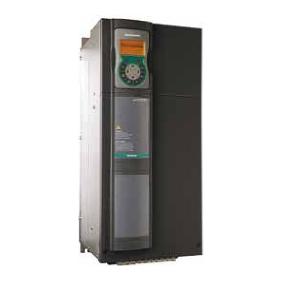
gefran AFE200 4 Series Instruction Manual

Active front end regenerative power supply unit
Table of Contents

Advertisement

Quick Links

Active Front End Regenerative
Power Supply Unit
AFE200-...-4
AFE200-...-6
Instruction Manual
......

Advertisement

Table of Contents
loading

Summary of Contents for gefran AFE200 4 Series

  • Page 1 Active Front End Regenerative Power Supply Unit AFE200-...-4 AFE200-...-6 Instruction Manual ..
  • Page 2: Information About This Manual

    Gefran S.p.A has the right to modify products, data and dimensions without notice. The data can only be used for the product description and they can not be understood as legally stated properties.
  • Page 3: Table Of Contents

    Table of contents Information about this manual ..........2 1 - Safety Precautions ............... 6 1.1 Symbols used in the manual ..................6 1.2 Safety precaution...................... 7 1.3 General warnings ..................... 7 1.4 Instruction for compliance with UL Mark (UL requirements), U.S. and Canadian electrical codes .......................
  • Page 4 6.2.4 List of the last parameters modified ..............61 6.2.5 “Goto parameter” function ..................61 6.3 Parameter modification................... 62 6.4 How to save parameters..................63 6.5 Configuration of the display ..................64 6.5.1 Language selection ....................64 6.5.2 Selection of Easy / Export mode ................64 6.5.3 Startup display .......................64 6.5.4 Back-lighting of the display..................64 6.6 Alarms........................
  • Page 5 Appendix 1 - Design .............. 188 A1.1 Single-motor calculation based on motor output power ........188 A1.2 Calculation for multi-motor system ..............189 Appendix 2 - Parallel connection (400 ... 1650kW sizes) ..192 A 2.1 Introduction......................192 A 2.2 Compatibility of IGBT modules ................. 194 A 2.3 MS-SL interface cable wiring sizes 400...710 kW ..........
  • Page 6: Safety Precautions

    1 - Safety Precautions 1.1 Symbols used in the manual Indicates a procedure, condition, or statement that, if not strictly observed, could result in personal injury or death. Indique le mode d’utilisation, la procédure et la condition d’exploitation. Si ces consignes ne Warning! sont passtrictement respectées, il y a des risques de blessures corporelles ou de mort.
  • Page 7: Safety Precaution

    Le système d’actionnement électrique (drive électrique + installation) ne peut être utilisé que dans les conditions d’exploitation et les lieux prévus dans le manuel et uniquement avec les dispositifs et les composants recommandés et autorisés par Gefran. 1.2 Safety precaution The following instructions are provided for your safety and as a means of prevent- ing damage to the product or components in the machines connected.
  • Page 8 Only suitable qualified personnel should work on this equipment, and only after becom- ing familiar with all safety notices, installation, operation and maintenance procedures contained in this manual. The successful and safe operation of this equipment is dependent upon its proper handling,installation, operation and maintenance. Seul un personnel dûment formé...
  • Page 9: Instruction For Compliance With Ul Mark (Ul Requirements), U.s. And Canadian Electrical Codes

    1.4 Instruction for compliance with UL Mark (UL require- ments), U.S. and Canadian electrical codes Short circuit ratings AFE200 must be connected to a grid capable of supplying a symmetrical short- circuit power of less than or equal to “xxxx A rms. The values of the “xxxx”...
  • Page 10: Introduction To The Product

    In this scenario, the input filter capacitors should be removed before powering up the unit from an AFE... For GEFRAN legacy or AC fed units, please consult the factory. For Other Brand products, consult the manufacturer of that product. Note! In order to work properly, an external LCL type line input filter and precharge kit is needed.
  • Page 11 braking. In conventional resistor braking systems this power is dissipated in the form of heat. The excess energy can be used to supply other equipment. Production of Clean Power The regeneration technology of the AFE200 uses advanced control algorithms to provide clean power.
  • Page 12: Product Type Designation

    4 = size 4 7 = size 7 5 = size 5 Active Front End Regenerative Power Supply Unit Identification Nameplate Serial number Gefran S.p.A via G.Carducci, 24 I-21040-Gerenzano, VA Model Type : AFE200-3220 -KXX-4 S/N: 09012345 Inp: 400Vac -15% ÷ 500 Vac +5% 50/60 Hz 3ph...
  • Page 13: Parallel Configurations

    The rated output current of the AFE200 must be higher or equal to the sum of the power ratings of the AFE200 connected to the DC-link. For further information please see Appendix 1. (*) The power rating in kW shown on the product data plate refers to that of the equivalent ADV200-DC. 2.1.1 Parallel configurations A parallel connection of several units basically consists of one MASTER unit and one or more SLAVE units.
  • Page 14: Transport And Storage

    3 - Transport and storage Correct transport, storage, erection and mounting, as well as careful operation and maintenance are essential for proper and safe operation of the equipment. Protect the AFE200 against physical shocks and vibration during transport and storage. Also be sure to protect it against water (rainfall) and excessive temperatures.
  • Page 15: Permissible Environmental Conditions

    3.2 Permissible Environmental Conditions Temperature storage �������������������� -25…+55°C (-13…+131°F), class 1K4 per EN50178 -20…+55°C (-4…+131°F), for devices with keypad transport ������������������� -25…+70°C (-13…+158°F), class 2K3 per EN50178 -20…+60°C (-4…+140°F), for devices with keypad Air humidity storage �������������������� 5% to 95 %, 1 g/m to 29 g/m (class 1K3 as per EN50178) transport �������������������...
  • Page 16: Mechanical Installation

    4 - Mechanical installation The AFE must be mounted on a wall that is constructed of heat resistant material. While the AFE is operating, the temperature of the AFE’s cooling fins can rise to a temperature of 158° F (70°C). Le AFE doit être monté...
  • Page 17: Fastening Positions

    4.2 Fastening positions 311 [12.24”] Fissaggio a muro Wall mounting 190 [7.48”] 268 [10.55”] 220 [8.66”] 187.6 [7.4”] 150 [5.91”] Taglia 5 Taglia 4 Taglia 3 Size 5 Size 4 Size 3 265 [10.43”] 267 [10.51”] 421 [16.57”] Fissaggio a muro Wall mounting 275 [10.83”] 175 [6.89”]...
  • Page 18 [16.42”] 355.6 [140”] 177.8 [7.00”] Fissaggio a muro Wall mounting (*) Protezione in policarbonato trasparente (*) Protective trasparent policarbonate [0.26”] Taglia 7 Size 7 [0.26”] 17.45 [0.69”] Taglie 1-2-3 Taglia 4 Sizes 1-2-3 Size 4 [0.21”] [0.26”] 12.5 [0.26”] [0.49”] [0.21”] Taglia 5 Taglia 6...
  • Page 19 [16.42”] [16.42”] 355.6 355.6 [140”] [140”] 177.8 177.8 [7.00”] [7.00”] Fissaggio a muro Wall mounting 400 ... 710 kW (*) Protezione in policarbonato trasparente (*) Protective trasparent policarbonate [16.42”] [16.42”] [16.42”] 355.6 355.6 355.6 [140”] [140”] [140”] 177.8 177.8 177.8 [7.00”] [7.00”] [7.00”]...
  • Page 20 [16.42”] [16.42”] [16.42”] [16.42”] 355.6 355.6 355.6 355.6 [140”] [140”] [140”] [140”] 177.8 177.8 177.8 177.8 [7.00”] [7.00”] [7.00”] [7.00”] Fissaggio a muro Wall mounting 1350 kW (*) Protezione in policarbonato trasparente (*) Protective trasparent policarbonate [16.42”] [16.42”] [16.42”] [16.42”] [16.42”] 355.6 355.6...
  • Page 21 [0.26”] [0.26”] 17.45 [0.69”] Recommended screws for fastening AFE200-72000-KXX-.-MS 04 400kW AFE200-72000-XXX-.-SL AFE200-72500-KXX-.-MS 05 500kW AFE200-72500-XXX-.-SL 12 x M6 x 16 mm screws + Grover (spring-lock) washer + Flat washer AFE200-73150-KXX-./..-MS 06 630kW AFE200-73150-XXX-./..-SL AFE200-73550-KXX-./..-MS 07 710kW AFE200-73550-XXX-./..-SL AFE200-73150-KXX-./..-MS 09 900kW AFE200-73150-XXX-./..-SL AFE200-73150-XXX-./..-SL...
  • Page 22: Wiring Procedure

    5 - Wiring Procedure AFE are electrical apparatus for use in industrial installations. Parts of the AFE are energized during operation. The electrical installation and the opening of the device should therefore only be carried out by qualified personnel. Improper installation of motors or AFE may therefore cause the failure of the device as well as serious injury to persons or material damage.
  • Page 23 - only one AFE200 is supplied from each RCD. - the output cables are less than 50m (screened) or 100m (unscreened). RCD: Residual Current Device RCCB: Residual Current Circuit Breaker ELCB: Earth Leakage Circuit Breaker Note: The residual current operated circuit-breakers used must provide protection against direct-current components in the fault current and must be suitable for briefly suppressing power pulse current peaks.
  • Page 24 capacitors may be impaired and must be “reformed”. Before commissioning devices that have been stored for long periods, connect them to a power supply for two hours with no load connected in order to regenerate the capacitors (the input voltage has to be applied without enabling the AFE).
  • Page 25: Power Section

    5.1 Power section 5.1.1 Cable Cross Section Terminals: C - D - U - V - W Sizes Maximum Cable Cross Section (flexible conductor) Recommended stripping Tightening torque (min) AFE200-...-4 (mm) (Nm) 3220 1.5 ... 1.7 4450 2.4 ... 4.5 5900 61320 Bars: C - D - U - V - W...
  • Page 26 Bars: C - D - U - V - W Sizes Lock screw Tightening torque Recommended cable cross-section AFE200-...-4 diameter (min) AWG / kcmil (mm) (Nm) AFE200-73550-KXX-4-MS 10 2 x 185 2 x kcmil 350 / 75 (U,V,W=M12) (M10) (M12) AFE200-73550-XXX-4-SL 2 x 185 2 x kcmil 350...
  • Page 27 Bars: C - D - U - V - W Sizes Recommended cable cross-section Lock screw diameter Tightening torque (min) AFE200-...-6 AWG / kcmil (mm) (Nm) 71600 AWG 4/0 72000 300 kcmil 72500 500 kcmil 73150 - 73550 2 x 100 2 x AWG 4/0 Terminals: on bars...
  • Page 28 Connection Sizes Recommended cable Lock screw Recommended Tightening AFE200-...-6 cross-section diameter terminal torque (min) AWG / kcmil (mm) (Nm) 72000-KXX-6-MS 04 AWG 2/0 Eyelet 400kW 72000-XXX-6-SL AWG 2/0 Eyelet 72500-KXX-6-MS 05 250 kcmil Eyelet 500kW 72500-XXX-6-SL 250 kcmil Eyelet 73150-KXX-6-MS 06 300 kcmil Eyelet 630kW...
  • Page 29: Emc Guide Line

    Note! For further information regarding electro-magnetic compatibility standards, according to Directive 2014/30/EC, conformity checks carried out on Gefran appliances, connection of filters and mains inductors, shielding of cables, ground connections, etc., consult the “Electro-magnetic compatibility guide” on the CD attached to this product.
  • Page 30: Block Diagram Power Section

    5.1.3 Block diagram power section AFE200-3220 ... 73550 PRECHARGE KIT Input AFE200- ... fuse DC LINK AFE200 : 400kW - 710kW PRECHARGE KIT Input fuse AFE200- ...- MS.. DC LINK Input AFE200- ...- SL.. fuse DC LINK AFE200 : 900kW - 1MW PRECHARGE KIT Input fuse...
  • Page 31 AFE200 : 1.35MW PRECHARGE KIT Input fuse AFE200- ...- MS.. DC LINK Input AFE200-- ...- SL.. fuse DC LINK Input AFE200- ...- SL.. fuse DC LINK Input AFE200- ...- SL.. fuse DC LINK AFE200 : 1.65MW PRECHARGE KIT Input fuse AFE200- ...- MS..
  • Page 32: Power Line Connection

    5.1.4 Power line connection L1 L2 L3 BR1 BR2 LR3-AFE EXP-SYNC-ADV card on SLOT2 LC-AFE EMI FILTER PRE CHARGE AFE200-3220...71600-4 (High Duty) AFE200-3220...61320-4 (Low Duty) 3ph - 380 V / 500 50/60 Hz (AFE200-...-4) AFE200-71600-6 (High Duty) 3ph - 500 V / 690 50/60 Hz (AFE200-...-6) LR3-AFE...
  • Page 33: Dc Output Connection

    5.1.5 DC output connection DC BUS External fuses Inverter 4 Inverter 3 Inverter 1 Inverter 2 AFE200 ADV200-DC ADV200-DC ADV200-DC ADV200-DC AC MAINS INPUT AFE200-3220 ... 4450 AFE200 ADV200-DC L1 L2 L3 BR1 BR2 L1 L2 L3 BR1 BR2 DC FUSES DC output - 650...780 V Common DC bus AFE200-5900 ...
  • Page 34 AFE200-71600 ... 73550 Common DC bus DC FUSES DC output - 650...780 V AFE200 ADV200-DC AFE200 : 400kW ... 710kW Common DC bus DC FUSES DC output - 650...780 V DC output - 650...780 V AFE200-...-SL-.. AFE200-...-MS-.. ADV200-DC AFE200 : 900kW - 1MW Common DC bus DC FUSES DC output - 650...780 V...
  • Page 35: Connection Of Fans Power Supply

    5.1.6 Connection of fans power supply Sizes Terminals 3220 ... 61320 No connection is necessary: the AFE’s internal power supply unit powers the fan (+24Vac). Version before 2009/125/CE (ErP regulation) Terminals 250V/10A contact OK fan contact management terminals 31-32: 1 x 230V (±10%) 50/60Hz, Ground Closed: Internal fan OK and powered;...
  • Page 36: Regulation Section

    5.2 Regulation section 5.2.1 Removing the terminal cover When removing the covers be carefull to lateral metal sheet enclosure. Presence of sharp edge are possible. Warning! 5.2.2 Cable Cross Section Maximum Cable Cross Section Recommended stripping Tightening torque (min) (min) Terminal strips (AWG) (mm)
  • Page 37 Table 5.2.3.1: Regulation terminals Strip T2 (top) Terminal Designation Function COM Digital output 2 Common reference for digital output 2 (Relay 2) Digital output 2 Programmable digital relay output 2 (NO). Default = Drive ready (PAR 1064) 250 V - 30 V / 2A Analog output 1 Analog output 1.
  • Page 38: Switches, Jumpers And Led

    It is not suitable to power supply the regulation card only through a unique rectifier and capacitive filter. La tension de + 24Vdc utilisée pour alimenter extérieurement la carte de régulation doit être stabiliséeet avec une tolérance de ±10% ; absorption maximum de 1A. Les alimentations obtenues avec les seules redresseur e filtre capacitive ne sont pas appropriées.
  • Page 39 +24 V R-ADV-AFE board To Expansion Cards +24 V Analog input 1 Analog output 1 Analog input 2 Analog output 2 +10V Digital input E mon 8 ( ) - 10V Precharge fbk src (*) fw 7.0 and lower only Precharge Command Digital output 1 to Auxiliary circuit...
  • Page 40 +24V OUT +24V OUT +24V OUT Enable Enable Enable Dig.inp E Dig.inp E Dig.inp E Precharge fbk Precharge fbk Precharge fbk Dig.inp 1 Dig.inp 1 Dig.inp 1 Dig.inp 2 Dig.inp 2 Dig.inp 2 Dig.inp 3 Dig.inp 3 Dig.inp 3 Dig.inp 4 Dig.inp 4 Dig.inp 4 Dig.inp 5...
  • Page 41: Serial Interface (Xs Connector)

    5.3 Serial interface (XS connector) Function Electr. interface PIN 1 Internal use – – PIN 2 Internal use – – PIN 3 RxA/TxA RS485 PIN 4 Equipotentiality (optional) – – 0V (Ground for 5 V) Power supply PIN 5 – PIN 6 +5 V –...
  • Page 42 RS485 (XS) Industrial PC Shielded cable with connectors, (with RS485) 5 mt (8S8F59) RS485 (XS) RS232 RS485 Shielded cable with connectors, PCI-COM (S5T60) 5 mt (8S8F59) RS485 (XS) RS232 Shielded cable with RS232 RS485 connectors, 5 mt (8S8F59) PCI-COM (S5T60) USB RS232 converter (8S8F62) Kit (S50T6) = Shielded cable 5 mt + PCI-COM...
  • Page 43: Afe / Rs485 Port Point-To-Point Connection (With Insulation)

    5.3.2 AFE / RS485 port point-to-point connection (with insulation) To make the connection with galvanic isolation, the OPT-RS485-ADV optional card is required. The card is equipped with a 9-pin D-SUB male connector which must be inserted in the XS connector of the AFE200. Connect terminals 1, 2 and 4 to the serial line as shown in the figure below;...
  • Page 44: Typical Connection Diagrams (With Pre-Charge Kit)

    5.4 Typical connection diagrams (with Pre-charge Kit) For Sizes: AFE200-3220...71600-4 (HD) AFE200-3220...61320-4 (LD) AFE200-71600-6 (HD) AFE200 • Instruction Manual...
  • Page 45 For Sizes: AFE200-72000...73550-4/-6 (HD) AFE200-71600...73550-4/-6 (LD) AFE200 • Instruction Manual...
  • Page 46 For parallel sizes: AFE200 400kW ... 1.65MW AFE200 • Instruction Manual...
  • Page 47 AFE200 • Instruction Manual...
  • Page 48: Precharge Kit

    5.5 Precharge Kit The pre-charge kit (mandatory) is not included in the AFE200 order code and must be ordered separately. The purpose of the pre-charge circuit is to charge the volt- age in the DC section with a specific charging time that depends on the DC Link capacitance value and pre-charge resistors.
  • Page 49: Pre-Charge Kit Dimensions And Cable Cross Section

    5.5.2 Pre-charge kit dimensions and Cable Cross Section 6 kg 13.2 lb Figure 5.5.1 : Pre-charge kit size 1 (cod. S72828 and S728281) 10 kg S728282 : 22 lb 10.5 kg S728283 : 23.1 lb Figure 5.5.2 : Pre-charge kit size 2 (cod. S728282 and S728283) AFE200 •...
  • Page 50 16 kg S728284 : 35.3 lb 16.5 kg S728285 : 36.4 lb Figure 5.5.3 : Pre-charge kit size 3 (cod. S728284 and S728285) U2, V2 (AC Input) (DC Output) Terminals: Terminals: Recommended Recommended Tightening Tightening Cable Cross Cable Cross Type Code torque (min) torque (min)
  • Page 51: Lcl Filters

    5.6 LCL Filters (1) LCL FILTER KIT (2) LCL FILTER KIT LC-AFE L-AFE C-AFE L -AFE C -AFE L1-2 L2-2 L3-2 L1-1 L2-1 L3-1 L1-2 L2-2 L3-2 L1-1 L2-1 L3-1 To AFE200 LR3-AFE LR3-AFE Sync Card (*) Thermal probe not available on sizes: LC-AFE-4-22HD-LD LC-AFE-4-45HD LCL filter must be connected between AFE and the AC line supply.
  • Page 52 AFE200-4 (kW) - Heavy Duty LCL Filters Type Code LCL-Kit-AFE-4-90-HD S7LC02 LCL-Kit-AFE-4-132-HD S7LC03 LCL-Kit-AFE-4-132-LD/160-HD S7LC04 LCL-Kit-AFE-4-160-LD/200-HD S7LC05 LCL-Kit-AFE-4-250-HD S7LC06 LCL-Kit-AFE-4-250-LD/315-HD S7LC07 LCL-Kit-AFE-4-315-LD/355-HD S7LC08 Table 5.6.2: LCL Filters / AFE200-4 matching (Low Duty) AFE200-4 (kW) - Low Duty LCL Filters Type Code LCL-Kit-AFE-4-22-LD S7LC15...
  • Page 53 LCL Filters Type Code LR3-AFE Code L-AFE Code C-AFE Code LCL-Kit-AFE-4-160-LD/200-HD S7LC05 LR3-AFE-4-200-HD S7ALC16 L-AFE-4-200-HD S7ALC15 C-AFE-4-33 S7ALC15C LCL-Kit-AFE-4-200-LD S7LC18 LR3-AFE-4-200-LD S7ALC46 L-AFE-4-200-LD S7ALC47 C-AFE-4-47 S7ALC3C LCL-Kit-AFE-4-250-LD/315-HD S7LC07 LR3-AFE-4-315-HD S7ALC18 L-AFE-4-315-HD S7ALC17 C-AFE-4-68 S7ALC17C LCL-Kit-AFE-4-315-LD/355-HD S7LC08 LR3-AFE-4-355-HD S7ALC6 L-AFE-4-355-HD S7ALC5 C-AFE-4-68 S7ALC17C LCL-Kit-AFE-4-355-LD...
  • Page 54: Lr3-Afe (Choke) Dimensions, Cable Cross Section And Data

    5.6.1 LR3-AFE (Choke) Dimensions, Cable Cross Section and data Morsetti sonde (≥ LR3-AFE-4-55-HD) Dimensions (mm) Weight Type Code Bars (kg) ~ Type LR3-AFE-4-22-HD S7ALC10 9x20 9x15 Ø7 AL20 x 3 1 x Ø7 LR3-AFE-4-22-LD S7ALC40 250±5 9x15 Ø7 AL20 x 3 1 x Ø7 LR3-AFE-4-45-HD S7ALC2...
  • Page 55 Bars: X1 U, X1 V, X1 W; X2 U, X2 V, X2 W on mechanical cabinet Recommended Cable Tightening torque Type Code Cable Cross Section Hole diameter Lock screw Recommended Cross Section (min) diameter terminal ) / AWG/kcmil (Nm) ) / AWG/kcmil (mm) LR3-AFE-4-160-HD S7ALC14...
  • Page 56: Lc-Afe (Choke + Capacitors) Dimensions, Cable Cross Section And Data

    5.6.2 LC-AFE (Choke + capacitors) Dimensions, Cable Cross Section and data LC-AFE-4-22-HD ... LC-AFE-4-45-HD LC-AFE-4-55-HD ... LC-AFE-6-160-HD d (approximated) Dissipated power Dimensions (mm) Weight Type Code 50 Hz 60 Hz Bars (kg) ~ LC-AFE-4-22-HD S7ALC9M 192.5 1 x Ø6 LC-AFE-4-22-LD S7ALC41M 192.5 1 x Ø6...
  • Page 57: L-Afe (Choke) Dimensions, Cable Cross Section And Data

    5.6.3 L-AFE (Choke) Dimensions, Cable Cross Section and data ØD Morsetti sonde X1L1 X1L2 X1L3 ØD X2L1 X2L2 X2L3 Ø7 Dimensions (mm) Weight Type Code Bars (kg) ~ Type L-AFE-4-200-HD S7ALC15 240 ±5 11x20 Ø 7 AL40x5 Ø 11 L-AFE-4-200-LD S7ALC47 355 ±5 11x20...
  • Page 58: C-Afe (Capacitor) Dimensions And Cable Cross Section

    5.6.4 C-AFE (Capacitor) Dimensions and Cable Cross Section Dimensions (mm) Weight Type Code (kg) ~ C-AFE-4-33 S7ALC15C C-AFE-4-47 S7ALC3C C-AFE-4-68 S7ALC17C C-AFE-6-22 S7ALC23C C-AFE-6-33 S7ALC25C C-AFE-6-47 S7ALC29C Terminals: X2 L1-2, X2 L2-2, X2 L3-2 Terminals: X2 L1-1, X2 L2-1, X2 L3-1 Maximum Cable Recommended Tightening torque...
  • Page 59: Use Of The Keypad

    6 - Use of the keypad This chapter describes the keypad and methods of use for display and program- ming of AFE200 parameters. 6.1 Description LCD display led is lit 7 virtual leds line: ILim led is off 01 MONITOR 02 DRIVE INFO Four alphanumeric lines 03 STARTUP WIZARD...
  • Page 60: Navigation

    LED’s meaning: the LED is lit, when the AFE operates with a positive torque the LED is lit, when the AFE operates with a negative torque the LED is lit, when the AFE is enabled The led is lit when the AFE is in local mode and OFF when in remote mode.
  • Page 61: Scanning Of The Parameters

    Depends on the type of parameter: ● Numeric parameter: displays the numeric value of the parameter, in the format required, and unit of measurement (figure A). ● Binary selection: the parameter may assume only 2 states, indicated as OFF-ON or 0 - 1 (figure B). ●...
  • Page 62: Parameter Modification

    of the parameter (PAR). When the parameter reached by the “Goto” command is displayed, it is possible to navigate all the parameters forming part of the same group using the ▲ and ▼ keys. Pressing the ► key returns to the “Goto” function. To exit the “Goto”...
  • Page 63: How To Save Parameters

    ILim 0 5 . 0 4 PA R : 6 0 8 DC volta g e ref src Test g en out Value: 5008 ILim ILim ILim 0 5 . 0 5 PA R : 6 0 8 0 5 . 0 4 PA R : 6 0 8 02 DRIVE INFO DC volta g e ref src...
  • Page 64: Configuration Of The Display

    6.5 Configuration of the display 6.5.1 Language selection Menu 04 DRIVE CONFIG, parameter 04.17 Language select, PAR: 578, default=English. Used to set one of the languages available : English, Italian, Francais, Deutsch, Polish, Romanian, Russian, Turkish and Portuguese. ILim ILim ILim 0 4 .
  • Page 65: Alarms

    Menu 04 DRIVE CONFIG, parameter 04.16 Display backlight, PAR : 576. Sets lighting of the display the light of the display remains always on. (default) the light switches off after approx. 3 minutes from pressing of the last key. 6.6 Alarms The alarms page is displayed automatically when an alarm occurs.
  • Page 66: Saving And Recovery Of New Parameter Settings

    ILim Message Load default Code: 0001H-1 Press ESC to exit MESSAGE : identifies a message. xx indicate show many messages are enqueued. The queue may contain a maximum of 10 messages and the message with the highest number is the most recent.
  • Page 67: Load Parameters From Keypad

    If an error occurs during transfer, the following message is displayed: ILim Message Save par failed Code: Press ESC to exit The code XX indicates the type of error, see paragraph 9.2. To exit from the error message, press the ESC key. 6.8.3 Load parameters from keypad Menu 04 DRIVE CONFIG, parameter 04.20 Load par from keypad, PAR : 592.
  • Page 68: Commissioning Via Keypad

    7 - Commissioning via keypad AFE are electrical apparatus for use in industrial installations. Parts of the AFE are energized during operation. The electrical installation and the opening of the device should therefore only be carried out by qualified personnel. Improper installation of motors or AFE may therefore cause the failure of the device as well as serious injury to persons or material damage.
  • Page 69 checking that the machine has been produced using those safety devices required by the 89/392/EEC set of rules, as far as the machine industry is concerned. These stand- ards do not apply in the Americas, but may need to be considered in equipment being shipped to Europe.
  • Page 70 Protect the device from impermissible environmental conditions (temperature, humidity, shock etc.). Protéger l’appareil contre des effets extérieurs non permis (température, humidité, chocs etc.). Caution To the output of the AFE (terminals C, D): - the direct connection of the inputs and outputs (bypass) are not permissible. À...
  • Page 71: Startup Wizard

    7.1 Startup Wizard Introduction The startup wizard is a guided procedure used for quick start-up of the AFE that helps to set the main parameters. It consists of a series of questions relating to the various sequences for entering and calculating the parameters necessary for correct AFE operation. The order of these sequences is as follows: See step 1 ●...
  • Page 72 Step 1 - Connections Connect the power supply line and enabling contacts as shown in the diagram in chapter 5.4.1. Checks to be performed before powering the AFE • Check that the supply voltage is correct and that the output terminals on the AFE (C, D) are connected correctly.
  • Page 73 ILim ILim ILim ILim ILim STARTUP WIZARD S E Q . 0 1 PA R : 6 0 0 1 3 . 0 1 S E Q . 0 1 PA R : PA R : 6 0 0 1 0 0 S E Q .
  • Page 74: Programming

    7.2 Programming 7.2.1 Menu display modes The programming menu can be displayed in two modes, which can be selected using the Access mode parameter (04 - DRIVE CONFIG menu), see chapter 6.5.2: • Easy (default) only the main parameters are displayed. •...
  • Page 75 Practical example The following examples illustrate the philosophies and methods with which more or less complex operations are performed in the single “function blocks”, the results of which represent the output of the block. • Example: Inverting the analog reference signal To invert the “Analog input 1 Block”...
  • Page 76: Description Of Parameters And Functions (Expert List)

    8 - Description of parameters and functions (Expert list) Legend           Menu Description Type FB BIT 1 - MONITOR ( Level 1 menu ) Output current FLOAT 16/32 Output voltage FLOAT 16/32 13.2 - FUNCTIONS/DOUBLE PAR SET ( Level 2 menu )
  • Page 77 1 - MONITOR The monitor menu displays the measured values of the sizes and of the AFE operating parameters. Menu Description Type FB BIT Output current FLOAT 16/32 The AFE output current is displayed. Menu Description Type FB BIT Output voltage FLOAT 16/32 Display of daisy-chained output voltage (*) of AFE.
  • Page 78 Menu Description Type FB BIT React curr ref mon FLOAT 16/32 The reactive current reference is displayed. Menu Description Type FB BIT Active current FLOAT 16/32 The active current value currently in use is displayed. Menu Description Type FB BIT Reactive current FLOAT 16/32...
  • Page 79 Menu Description Type FB BIT 1.17 1066 Enable state mon The AFE Enable command status is displayed. Voltage must be present on terminal 7. The FR Forwardstart command is needed to start the AFE200. Disabled AFE disabled Enabled AFE enabled Menu Description Type...
  • Page 80 Menu Description Type FB BIT 1.21 1400 Digital output X mon UINT16 The status of the digital outputs of the expansion card is displayed. It can also be read via a serial line or fieldbus. The data are contained in a word, where each bit is 1 if voltage is supplied to the corresponding input terminal.
  • Page 81 2 - DRIVE INFO This menu displays the information for identifying and configuring the AFE. Menu Description Type FB BIT Drive size UINT16 The AFE size identification code is displayed. Menu Description Type FB BIT Drive family ENUM No Power The available mains voltage is displayed (e.g.
  • Page 82 Menu Description Type FB BIT Application ver.rel UINT16 The version number and release number of the application are displayed. Menu Description Type FB BIT Application type UINT16 The type of application currently used by the AFE is displayed. Menu Description Type FB BIT Actual date time...
  • Page 83 Menu Description Type FB BIT 2.18 Slot1 card type ENUM None 2.19 Slot2 card type ENUM None 2.20 Slot3 card type ENUM None The type of expansion card installed in the relative slot of the AFE is displayed. None I/O 1 (EXP-IO-D6A4R1-ADV) 1793 I/O 2...
  • Page 84 3 - STARTUP WIZARD The startup wizard menu suggests a procedure for commissioning the AFE quickly with a reduced number of settings. Advanced customization requires the use of the single parameters relating to the specific performance levels. See the procedure described in the previous Startup wizard chapter. AFE200 •...
  • Page 85 4 - CONFIG DRIVE Menu Description Type FB BIT Save parameters Any changes to parameter values immediately affect AFE operations, but are not automatically saved in the permanent memory. The “Save Parameters” command is used to save current parameter values in the permanent memory.
  • Page 86 Done The parameter displays the Required message when the motor parameters that have been entered need to be saved. When they have been saved the parameter indicates Done. Menu Description Type FB BIT Application select ENUM None ERWZ Selection of which IEC 61131-3-compliant application to make operational. None Application 1 Application 2...
  • Page 87 4 kHz 6 kHz 8 kHz 10 kHz 12 kHz 16 kHz Menu Description Type FB BIT 4.11 Ambient temperature ENUM 40 degC ERWZ Setting of the ambient temperature value. This parameter is used to set the output cur- rent derating factor (1% for every °C above 40°C). 40 degC 50 degC 40 degC...
  • Page 88 Menu Description Type FB BIT 4.14 Startup display INT16 20000 ERW It is possible to set the parameter that will automatically be displayed when the AFE is switched on. If set to -1 the AFE moves to the display menu. Menu Description Type...
  • Page 89 5 - REFERENCE AFE have a DC-link voltage regulation circuit; which can be adapted to suit the various applications. In the standard version, the regulator has PI behaviour and the regulator parameters are the same for the entire field of regulation. Menu Description Type...
  • Page 90 6 - COMMANDS It is possible to work in Local or Remote mode. When switching between Remote and Local modes the origin of the Enable and Start commands is switched. In Remote mode the “Commands remote sel” parameter is used to configure the source of the En- able and Start commands which can be Terminal (standard digital input, expansion digital input) or Digital (Modbus, Fieldbus).
  • Page 91 Example 2 With the machine controlled from console A, the AFE operates in Local -> Terminal -> Standard digital input mode. With the machine controlled from console B, the AFE operates in Remote ->Digital -> Expansion digital input mode. When switching the control console, the AFE must switch between Remote and Local mode. The switch command must be sent via Standard digital input or Expansion digital input.
  • Page 92 Inactive EmgStop&Alarm If the command is set to Inactive, pressing the Stop key on the keypad is ineffective. If the command is set to EmgStop&Alarm, when the Stop key is pressed the motor stops in FastStop mode and the Emg stop alarm is generated. When the motor reaches the speed=0, the drive is automatically disabled and waits for the Fault reset command.
  • Page 93 Menu Description Type FB BIT 1018 Digital Enable src LINK 6000 16384 ERW L�DIGSEL2 Selection of the origin (source) for the Digital Enable signal. The signal to be associ- ated with this function can be selected from the “L_DIGSEL2” selection list. Menu Description Type...
  • Page 94 7 - DIGITAL INPUTS AFE200 • Instruction Manual...
  • Page 95 Menu Description Type FB BIT 1132 Dig inp 1 inversion 1134 Dig inp 2 inversion 1136 Dig inp 3 inversion 1138 Dig inp 4 inversion 1140 Dig inp 5 inversion Reversal of the logic status of the function associated with the digital input (e.g. from enabled with +24V signal to enabled with low signal).
  • Page 96 7.42 5582 Dig input15X dest ILINK 7.43 5584 Dig input16X dest ILINK Selection of the destination of the associated digital input of the expansion card. AFE200 • Instruction Manual...
  • Page 97 8 - DIGITAL OUTPUTS AFE200 • Instruction Manual...
  • Page 98 Menu Description Type FB BIT 1310 Digital output 1 src LINK 1122 16384 1312 Digital output 2 src LINK 1064 16384 1314 Digital output 3 src LINK 1062 16384 1316 Digital output 4 src LINK 6000 16384 L�DIGSEL1 Selection of the origin (source) of the signal to be assigned to the relative digital output.
  • Page 99 Menu Description Type FB BIT 1500 Analog input 1 mon INT16 16/32 9.17 1550 Analog input 2 mon INT16 16/32 The value of the voltage on the output of the function block of the relative analog input is displayed. Menu Description Type FB BIT...
  • Page 100 9.18 1552 Analog inp 2 type ENUM -10V..+10V Selection of the type of input (voltage or current). Depending on the input signal, move the switches on the regulation card. The factory parameter is inputs set for differential voltage signals (± 10V). -10V..+10V 0.20mA ...
  • Page 101 command is sent, An inp x offset tune is automatically selected so that the available input signal corresponds to the zero value of the variable. Offset tuning can also be performed with the AFE enabled. Automatic tuning can only be performed if the follow- ing condition is present: Automatic tuning can only be performed if the following condition is present: - Input voltage less than 1V or input current less than 2 mA...
  • Page 102 Menu Description Type FB BIT 1514 Analog inp 1 bottom INT16 -16384 -32768 +32767 ERW 9.24 1564 Analog inp 2 bottom INT16 -16384 -32768 +32767 ERW Setting of the lower speed reference limit as a function of the voltage (or current) of the relative analog reference..
  • Page 103 x = 1, 2 Analog inp x thr Analog inp x <thr x = 1, 2 Analog inp x thr Analog inp x <thr Menu Description Type FB BIT 9.12 1522 An inp 1 deadband perc FLOAT 100.0 9.28 1572 An inp 2 deadband perc FLOAT...
  • Page 104 AnInp Drive 100% -10V Par.1522=50% -100% AnInp Terminal Par.1522=50% 100% -100% Menu Description Type FB BIT 9.13 1524 An inp 1 alt value INT16 16/32 -16384 16384 ERW 9.29 1574 An inp 2 alt value INT16 16/32 -16384 16384 ERW Setting of a fixed alternative value for the relative analog input, which can be selected via a command enabled by a digital input programmed with the An inp alt sel src parameter.
  • Page 105 The value of the voltage output of the function block of the relative analog input is displayed. Menu Description Type FB BIT 9.34 1602 Analog inp 1X type ENUM -10V..+10V 9.45 1652 Analog inp 2X type ENUM -10V..+10V Selection of the type of expansion card input (voltage or current input). Depending on the input signal, move the switches on the regulation card.
  • Page 106 9.47 1656 An inp 2Xoffset tune Self-tuning command for the offset of the relative analog input of the expansion card. Automatic fine tuning of the input. To perform self-tuning, set the input signal to its minimum value and execute the command. The conditions containing an offset can be compensated.
  • Page 107 Setting of an offset value to algebrically add to the relative analog input of the expan- sion card. Menu Description Type FB BIT 9.40 1616 Analog inp 1X offset INT16 -32768 +32767 ERW 9.51 1666 Analog inp 2X offset INT16 -32768 +32767 Setting of an offset value to algebrically add to the relative analog input of the expan-...
  • Page 108 The function for which the relative analog input of the expansion card has been pro- grammed and on which it acts is displayed. Menu Description Type FB BIT 9.55 5410 Analog inp 0Ext mon INT16 16BIT -32768 32767 9.56 5412 Analog inp 1Ext mon INT16 16BIT...
  • Page 109 PAR1552). Signal connected: -10V..+10V An input type -10V +10V -10V..+10V Bottom Obtained from straight line 0V..+10V Less than 0V saturation Bottom at Bottom 4.0.20 mA Less than 2V saturation Bottom at Bottom Signal connected: 0V..+10V An input type +10V -10V..+10V Obtained from straight line 0V..+10V Bottom...
  • Page 110 10 - ANALOG OUTPUTS On the AFE200 regulation card there are two programmable analog outputs. Analog output 1 supplies a two-pole +/-10VDC voltage signal, while analog output 2 can be pro- grammed to obtain a 0-20mA or 4-20mA output signal in current or a signal in two-pole +/-10VDC voltage, depending on the parameter assigned.
  • Page 111 1500 Analog input 1 mon 1550 Analog input 2 mon 10V = 10V Analog input 1600 Analog input 1X mon 1650 Analog input 2X mon Drive overload accum 5V = 100% Accumulator 4024 … 4174 Fieldbus M->SX mon 10V = 16384 * 2^16 3700 …...
  • Page 112 Example of calculation of scale factor Analog out x scale : To display the AFE speed, use an analog instrument with field of measurement from 0...2V. This means that, to display the speed of the AFE, a voltage of 2V on the analog output of the AFE must correspond to the maximum speed.
  • Page 113 Select option 1 in order to apply a maximum voltage of +10V or a signal in current of 0 ... 20 mA to analog output 2. The signal must be positive. Select option 2 to apply a signal in current of 4...20 mA to analog output 2. Menu Description Type...
  • Page 114 Menu Description Type FB BIT 10.18 1866 Analog out 1X mon INT16 The actual value of the voltage present on analog output 1 of the expansion card is displayed. Menu Description Type FB BIT 10.19 1868 Analog out 2X mon INT16 The actual value of the voltage or current present on analog output 2 of the expansion card is displayed.
  • Page 115 10.31 5468 Dig Analog out 4 ext INT16 16BIT -32768 32767 ERW 10.32 5470 Dig Analog out 5 ext INT16 16BIT -32768 32767 ERW 10.33 5472 Dig Analog out 6 ext INT16 16BIT -32768 32767 ERW 10.34 5474 Dig Analog out 7 ext INT16 16BIT -32768...
  • Page 116 11 - REGULATOR PARAM Menu Description Type FB BIT 11.1 2250 Current reg P gain FLOAT CALCF ERWS Setting of the proportional coefficient of the current regulator. Menu Description Type FB BIT 11.2 2252 Current reg I time FLOAT CALCF ERWS Setting of the integral coefficient of the current regulator.
  • Page 117 The dead time compensation function (Dead time compensation), compensates the distortion of output voltage caused by the voltage drop on the IGBT devices and their switching characteristics. Menu Description Type FB BIT 11.5 2280 Dead time limit FLOAT SIZE 50.0 ERWS Setting of the dead time voltage compensation value.
  • Page 118 12 - ACTIVE CURR CONFIG Menu Description Type FB BIT 12.1 2350 Active curr lim Pos FLOAT 16/32 CALCF CALCF ERWS Setting of the AFE active current limit for the positive current direction. Menu Description Type FB BIT 12.2 2352 Active curr lim Neg FLOAT 16/32...
  • Page 119 torque Torque curr lim Pos Torque curr lim Pos speed Torque curr lim Neg Torque curr lim Neg Menu Description Type FB BIT 12.4 2358 Active curr lim src LINK 16/32 6000 16384 ERWZ L�LIM Selection of the origin (source) to be used to set the active current limit. The signals that can be associated with the function can be selected from the “L_LIM”...
  • Page 120 13 - FUNCTIONS 13.1 - Reserved for AFE200-PV. 13.2 - FUNCTIONS/DOUBLE PAR SET Two independent sets of parameters can be stored in the AFE200. These can be selected via the keypad or by using an external command. This makes it possible to change all the AFE parameters quickly and automatically according to the various operating requirements.
  • Page 121 Menu Description Type FB BIT 13.2.3 3304 Par set select mon ENUM Set 0 The parameter set currently in use is displayed. Set 0 Set 1 Menu Description Type FB BIT 13.2.4 3306 Par set 0 to 1 copy Procedures for setting up and managing the double parameter set Creating the second set: This function copies parameter set 0 onto set 1.
  • Page 122 13.3 - FUNCTIONS/COMPARE This function allows the comparison among two signals or values. Menu Description Type FB BIT 13.3.1 3650 Dig compare input 1 perc FLOAT -100.0 100.0 Setting of the digital value of the first element of comparison. Menu Description Type FB BIT...
  • Page 123 Ingr1!=Ingr2 Ingr1<Ingr2 Inrg1>Ingr2 |Ing1|=|Ing2| |Ing1|!=|Ing2| |Ing1|<|Ing2| |Ing1|>|Ing2| If set to 0 the comparator is not enabled If set to 1 the comparator output is enabled when the value of Dig compare input 1 is inside the window resulting from the value of Dig compare input 2 ± the tolerance set via the Comparator Window.
  • Page 124 13.4 - FUNCTIONS/PADS The general variables are used to exchange data between the various components of a Bus system. They are similar to the variables of a PLC. The basic structure of the system is illustrated below. Pads can be used, for example, to send information from a fieldbus to an optional card. All Pads can be read and written.
  • Page 125 14 - COMMUNICATION The AFE200 is provided with a standard port (9 pole sub-D connector: XS) for connecting the RS485 serial line used for AFE-PC point-to-point communication (via the GF-eXpress configuration software) or for the multidrop connection. The RS485 serial line format is: 8 data bits, no parity and one stop bit. 14.1 - COMMUNICATION/RS485 Menu Description...
  • Page 126 Example: if the delay in Tx/Rx switching on the master is a maximum of 20ms, the Ser answer delay parameter must be set to at least 20ms: 22ms Menu Description Type FB BIT 14.1.6 3808 Serial swap data This parameter enables the exchange of the reading of the High and Low parts of the words for FLOAT type parameters when using the Modbus protocol.
  • Page 127 Menu Description Type FB BIT 14.2.4 4010 Fieldbus M->S enable ENUM Enable ERWZ Setting of fieldbus data updating. Disable Enable If set to 0, the possibility of sending commands and references from the AFE PLC via the fieldbus is disabled. If set to 1 the possibility of sending commands and references from the AFE PLC via the fieldbus is enabled.
  • Page 128 Menu Description Type FB BIT 14.2.8 5608 IP address UINT32 4294967295 Display of DCP address set via configuration of Profinet node. 14.3 - COMMUNICATION/FIELDBUS M2S Menu Description Type FB BIT 14.3.1 4020 Fieldbus M->S1 ipa FBM2SIPA 14.3.5 4030 Fieldbus M->S2 ipa FBM2SIPA 14.3.9 4040...
  • Page 129 Not assigned Count 16 Count 32 Fill 16 Fill 32 Mdplc 16 Mdplc 32 Eu float Par 16 Par 32 If set to 0 the channel is not assigned. If set to 1 the datum is assigned a 16-bit count. If set to 2 the datum is assigned a 32-bit count.
  • Page 130 Sys parameter FB type result Count 32 32 bit Receives 32 bits from FB and copies to 32 bits of monitor. OK 32_H Receives 32 bits from FB and copies to 32 bits of monitor. OK 32_L Receives 32 bits from FB and copies to 32 bits of monitor. OK Count 16 16 bit Receives 16 bits from FB and doesn’t know whether to copy to 16H or 16L of...
  • Page 131 14.4.37 4270 Fieldbus S->M10 ipa FBM2SIPA 20000 14.4.41 4280 Fieldbus S->M11 ipa FBM2SIPA 20000 14.4.45 4290 Fieldbus S->M12 ipa FBM2SIPA 20000 14.4.49 4300 Fieldbus S->M13 ipa FBM2SIPA 20000 14.4.53 4310 Fieldbus S->M14 ipa FBM2SIPA 20000 14.4.57 4320 Fieldbus S->M15 ipa FBM2SIPA 20000 14.4.61 4330...
  • Page 132 If set to 10 the datum is assigned a 32-bit integer engineering unit format or float for- mat if the associated parameter is a float-type parameter not in real time (5-10ms) Note! If the sys parameter is not assigned, none of the subsequent channels are transferred to the fieldbus, even if programmed.
  • Page 133 The Fieldbus S->Mx mul parameters are multipliers that the AFE applies to the datum before sending it to the bus. It is therefore possible to increase the resolution of some values read in EU and EU_float mode, also using decimal digits. Note! The AFE does not check that the multiplied parameter expressed in bits fits in a 16-bit integer.
  • Page 134 14.6 - COMMUNICATION/WORD DECOMP Menu Description Type FB BIT 14.6.1 4450 Dig word decomp UINT32 Setting of the digital input decoded by the “Word decomp” block. Menu Description Type FB BIT 14.6.2 4452 Word decomp src LINK 4450 16384 ERW L�WDECOMP Selection of the origin (source) of the word to be decoded by the “Word decomp”...
  • Page 135 Menu Description Type FB BIT 14.7.1 5480 External IO enable ENUM Disable This parameter is used to enable or disable communication between the EXP-FL- XCAN-ADV card and the external device. Disable Enable Communication is disabled in the default configuration. Communication can be ena- bled by setting Enable and saving the parameters.
  • Page 136 14.8 - COMMUNICATION/FAST LINK The optional EXP-FL-XCAN-ADV card (generally inserted in slot 1) allows the number of I/Os man- aged by the drive to be increased, using an external device. Communication with the external device is performed via CAN using the “DS401 Device profile for generic IO modules”. For more details see manual 1S5F32_EXP-FL-XCAN-ADV.
  • Page 137 1 Pwm The Fastlink transfers information between the drives and the function for synchronising the generation of Pwm signals with the Pwm signals of the master is enabled. The variables in the 11) Updating times for the various functions table are synchronised at 125 us 2 Pwm&Ctrl The Fastlink transfers information between the drives, the function for synchronising the generetion of Pwm signals with the Pwm signals of...
  • Page 138 This parameter is used to disable the alarm at power-off by connecting the “FL fault enable src” parameter to “Enable state mon”. Menu Description Type FB BIT 14.8.7 5730 FL Fwd 1 src LINK 16/32BIT 6000 16384 ERW 14.8.8 5732 FL Fwd 2 src LINK 16/32BIT 6000...
  • Page 139 14.8.24 5856 FL Rev 4 mon INT32 32BIT Display of data selected via parameters FL Rev X Slave sel corresponding (PAR 5822 ... 5828). Menu Description Type FB BIT 14.8.25 5822 FL Rev 1 slave sel UINT16 ERWZ 14.8.26 5824 FL Rev 2 slave sel UINT16 ERWZ...
  • Page 140 15 - ALARM CONFIG In the ALARM CONFIG menu the type of effect any alarm signals have on the AFE product is deter- mined: - The alarm status is saved - How must the AFE product react to the alarm signal? - Auto restart - Alarm reset For some alarms, behaviour can be configured separately for each signal, while for the others the Dis-...
  • Page 141 Alarm Ignore Warning Disable drive ExtIO activity 4690 √ √ √ FL fault activity 4940 √ √ √ Menu Description Type FB BIT 15.1 4500 Fault reset src LINK 16BIT 1120 16384 DIGSEL2 Selection of the origin (source) of the signal to be used for the command to reset the AFE product after an alarm.
  • Page 142 Menu Description Type FB BIT 15.7 4510 ExtFlt holdoff UINT16 10000 Setting of the delay between the signalling of the External Fault [20] alarm and ena- bling of the alarm. If an alarm condition occurs, the AFE product will wait for the set time to activate the alarm.
  • Page 143 Menu Description Type FB BIT 15.14 4570 Drive ovld activity ENUM Ignore Setting of the behaviour of the AFE product in case of a Drive overload [14] alarm. This alarm indicates that the AFE product overload threshold has been reached. Ignore Warning Disable...
  • Page 144 Menu Description Type FB BIT 15.21 4610 Desat restart ENUM Disable Enabling of automatic restart after the desaturation alarm Desaturation [5]. This alarm indicates a short circuit between the phases of the power bridge. Disable Enable Menu Description Type FB BIT 15.22 4612 Desat restart time...
  • Page 145 Setting of the time within which the Undervoltage [2] alarm must be reset in order to perform automatic restart. (Time with alarm signal active + 100 msec). Menu Description Type FB BIT 15.29 4650 UVRep attempts UINT16 1000 Setting of the maximum number of attempts at automatic restart after the Undervolt- age [2] alarm before a Mult Undervoltage [6] alarm is generated.
  • Page 146 The following activities are programmable: Ignore Warning Disable Menu Description Type FB BIT 15.34 4680 GroundFault thr perc FLOAT 10.0 150.0 ERWS Setting of the threshold for the ground short circuit alarm Ground Fault [3]. Menu Description Type FB BIT 15.35 4700 Alarm dig sel 1...
  • Page 147 Plc7 fault Plc8 fault Menu Description Type FB BIT 15.39 4720 Alm autoreset time FLOAT 60.0 Setting of the time interval that must pass before executing an automatic reset. If no alarms are enabled the AFE product is set to restart. If some alarms are still enabled the AFE product is set to execute a new attempt at automatic reset.
  • Page 148 16 - ALARM LOG This is the menu in which the log of previous alarms is saved, with the time the alarm occurred (in relation to the Time drive power on parameter). The alarms are displayed starting from the most recent (No. 1) up to the furthest back in time (No. 30). Up to 30 alarm signals can be displayed.
  • Page 149 17 - PLC LOG Reserved for AFE200-PV. 18 - APPLICATION This menu is designed to host two customized applications using the MDPlc program, currently in progress. It will not be possible to use both applications simultaneously. PAR 558 Application select parameter in the DRIVE CONFIG menu must be used to select between the two possible applications.
  • Page 150: Parameters On Selection Lists, But Not Displayed On Keypad

    8.1 Parameters on selection lists, but not displayed on key- Menu Description Type FB BIT Drive overload trip 16BIT This signal indicates that the AFE product is in the overload alarm condition. Menu Description Type FB BIT Drive overload 80% 16BIT This signal indicates that the AFE product has reached 80% of the thermal image ac- cumulator (Drive overload).
  • Page 151 Menu Description Type FB BIT 1210 Digital input 1X mon 16BIT 1212 Digital input 2X mon 16BIT 1214 Digital input 3X mon 16BIT 1216 Digital input 4X mon 16BIT 1218 Digital input 5X mon 16BIT 1220 Digital input 6X mon 16BIT 1222 Digital input 7X mon...
  • Page 152 Menu Description Type FB BIT 4712 Alm dig out mon 3 16BIT This signal is activated when the alarm configured in parameter 4704 alarm dig sel 3 is active. Menu Description Type FB BIT 4714 Alm dig out mon 4 16BIT This signal is activated when the alarm configured in parameter 4706 alarm dig sel 4 is active.
  • Page 153 This parameter displays the state of the alarms generated by the application written with the internal PLC Description 1 = PLC 1 fault active 1 = PLC 2 fault active 1 = PLC 3 fault active 1 = PLC 4 fault active 1 = PLC 5 fault active 1 = PLC 6 fault active 1 = PLC 7 fault active...
  • Page 154 Description 1 = PLC 3 fault active 1 = PLC 4 fault active 1 = PLC 5 fault active 1 = PLC 6 fault active 1 = PLC 7 fault active 1 = PLC 8 fault active Menu Description Type FB BIT 5800 FL Fwd 1 inv mon...
  • Page 155: Selection Lists

    8.2 Selection Lists PAR Description Menu PAR Description Menu PAR Description Menu L_ANOUT L_CMP (1) the XXXX parameter changes accord- 6000 Null XXXX (1) ing to the src parameter used: Output current Output current Output voltage Output voltage Output frequency Output frequency 3660 Compare input 1 src Active current ref...
  • Page 156 PAR Descrizione Menu PAR Description Menu PAR Description Menu 3704 Pad 3 13.4.3 3712 Pad 7 13.4.7 4480 Bit13 decomp mon 14.6.16 3706 Pad 4 13.4.4 3714 Pad 8 13.4.8 4482 Bit14 decomp mon 14.6.17 3708 Pad 5 13.4.5 3716 Pad 9 13.4.9 4484 Bit15 decomp mon 14.6.18...
  • Page 157 PAR Description Menu PAR Description Menu PAR Description Menu 3700 Pad 1 13.4.1 4034 Fieldbus M->S2 mon 14.3.7 Active current 3702 Pad 2 13.4.2 4044 Fieldbus M->S3 mon 14.3.11 Reactive current 3704 Pad 3 13.4.3 4054 Fieldbus M->S4 mon 14.3.15 2360 Active climPos Inuse 12.5 3706 Pad 4...
  • Page 158 PAR Descrizione Menu PAR Description Menu PAR Description Menu 5850 FL Rev 1 mon 14.8.21 3702 Pad 2 13.4.2 3714 Pad 8 13.4.8 5852 FL Rev 2 mon 14.8.22 3704 Pad 3 13.4.3 3716 Pad 9 13.4.9 5854 FL Rev 3 mon 14.8.23 3706 Pad 4 13.4.4...
  • Page 159 PAR Description Menu PAR Description Menu PAR Description Menu 3712 Pad 7 13.4.7 3714 Pad 8 13.4.8 3716 Pad 9 13.4.9 3718 Pad 10 13.4.10 3720 Pad 11 13.4.11 3722 Pad 12 13.4.12 3724 Pad 13 13.4.13 3726 Pad 14 13.4.14 3728 Pad 15 13.4.15...
  • Page 160: Troubleshooting

    9 - Troubleshooting 9.1 Alarms Note ! To reset alarms, see Quick start guide, paragraph 6.6.1. In the following table, the Code is visible only from serial line. Sub-code Code Error message shown Description on the display Condition: No alarm present No alarm Condition: DC link overvoltage alarm due to energy recovered from the motor.
  • Page 161 Sub-code Code Error message shown Description on the display Solution: Check the cables connected to the mains voltage measurement card. - Check for the presence of the mains voltage The measured mains voltage is too high Overvoltage AC Solution: Check the cables connected to the mains voltage measurement card. - Check the readings of parameters PAR 256 Phase U voltage, PAR 258 Phase V voltage, PAR 260 Phase W voltage Condition: Heatsink temperature too high alarm...
  • Page 162 Sub-code Code Error message shown Description on the display Condition: External alarm present. External fault A digital input has been programmed as an external alarm, but the +24V voltage is not available on the terminal. Solution: Check that the terminal screws are tight Condition: Emergency stop alarm.
  • Page 163: Extio Fault" Alarm

    9.1.1 “ExtIO fault” Alarm The drive may generate an “ExtIO fault” alarm for a series of reasons. At drive startup there may be problems with configuration, associated with the EXP-FL- XCAN-ADV card or parameter settings. During the Config phase the alarm might depend on an SDO communication error.
  • Page 164: Fastlink Fault" Alarm

    Cause: The firmware on the optional FastLink card is incompatible with that on the Compatibility regulation card. error Solution: Contact Gefran in order to update the firmware on the optional fastlink card. Cause: situation in which an interrogated Slave does not reply Slave answer Solution: check FastLink connection...
  • Page 165: Messages

    Number of hours for which the function can still be used freely. Solution: Ask Gefran for the correct key to enable the desired firmware function. Condition: may occur during loading of the parameter database saved in flash normally appears in the following conditions: at initial power-on when a new firmware version is downloaded, when the regulation is installed on a new size, when the region is changed.
  • Page 166 Error message shown on the Sub-code Description display 002AH-42 PLC application release and version not compatible. All parameters in the keypad memory have been transferred to the AFE. The transferred set of parameters relates to a AFE with a PLC application in which the version and release of the application are different.
  • Page 167 Error message shown on the Sub-code Description display Condition: may occur during recognition of power cards. The AFE cannot be enabled when this Power config message is shown. 0020H-32 The power card is configured for a AFE that is incompatible with the regulation card 0021H-33 The configuration of the power card is not compatible with the regulation card 0017H-23 The configuration required is not available on the power card Solution: Download the correct configuration on the power card...
  • Page 168: Specification

    10 - Specification 10.1 Environmental Conditions Installation location ������������������Pollution degree 2 or lower (free from direct sunligth, vi- bration, dust, corrosive or inflammable gases, fog, vapour oil and dripped water, avoid saline environment) Installation altitude ������������������Max 2000m (6562 feet) above sea level;. Mechanical conditions for installation ���Vibrational stress: EN 60721-3-3 Class 3M1 Operating temperature ��������������-10…+40°C (32°…104°F) Operating temperature (1) ������������+40 ...
  • Page 169: Overload

    10.4 Overload Heavy duty (HD) 150% 60 sec every 300 sec, 180% 0,5 sec. Light duty (LD) 110% 60 sec every 300 sec. 10.5 DC circuit DC-link voltage rating �����������������650...780 V (aFE-...-4), 820...1120 V (aFE-...-6) DC overvoltage threshold ��������������820 V (aFE-...-4), 1192 V (aFE-...-6);...
  • Page 170: Electrical Data

    10.6 Electrical data Input voltage (AFE200-...-4) �������������380 - 15% ... 500 +5% V Input voltage (AFE200-...-6) ������������500 - 10% ... 690 +10% V Input frequency ����������������������50/60 Hz ±2% Maximum line voltage unbalance ���������3 % THd Input current ��������������������≤ 3% (considering AC Mains THD Voltage <2%) Cosphi ����������������������������≥...
  • Page 171 input current output current Derating factor Switching frequency Sizes Heavy duty Light duty Heavy duty Light duty Default Higher Light eavy AFE200-...-6 duty duty (kHz) (kHz) 630kW 710kW 645 (5) 0.85 900kW 1012 920 (5) 1050 1012 1155 0.85 1,35MW 1200 (5) 1350 1320...
  • Page 172: Voltage Level Of Afe200 For Safe Operations

    10.7 Voltage level of AFE200 for safe operations The minimum time between the moment in which an AFE200 is disabled from the mains and that in which an operator can operate on internal parts of the product, without the danger of electric shock, is 5 minutes. The value consider the time to turn-off for an AFE200 without any options (time indicated for disabled AFE200 condition).
  • Page 173: Cooling

    10.8 Cooling All the AFE200 have internal fans. Dissipated power Airflow of fan Sizes AFE200- Heatsink (m Internal (m 3220 80 x 2 4450 2 x 250 2 x 50 5900 1420 2 x 355 2 x 170 61320 2000 3 x 310 2 x 170 71600...
  • Page 174: Weight And Dimensions

    10.9 Weight and dimensions Dimensions: Width x Height x Depth Weight Sizes AFE200-...-. [mm] [inches] (kg) (lbs) 3220 180 x 517 x 250.1 7.09 x 20.35 x 9.85 39,7 4450 268 x 616 x 270 10.55 x 24.25 x 10.63 52,9 5900 311 x 730.4 x 325...
  • Page 175 268 [10.55”] Figure 10.9.2: Size 4 dimensions 311 [12.24”] 325 [12.80”] 45.5 [1.79”] 190 [7.48”] 265 [10.43”] Figure 10.9.3: Size 5 dimensions AFE200 • Instruction Manual...
  • Page 176 421 [16.57”] 360 [14.17”] 275 [10.83”] 175 [6.89”] 350 [13.78”] Figure 10.9.5: Size 6 dimensions 355.6 (16.4) (14.0) 177.8 Vista senza protezioni (*) Protezione in policarbonato trasparente View without protections (*) Protective trasparent policarbonate (19.1) Figure 10.9.6: Size 7 dimensions AFE200 •...
  • Page 177 837 mm [32.95”] 485 mm [19.09”] 355.6 mm [14”] 420 mm 177.8 mm [16.54”] [7”] dettaglio fissaggio inferiore 6.5mm Figure 10.9.6: Sizes 400...710kW dimensions AFE200 • Instruction Manual...
  • Page 178 1257 mm [49.49”] interasse di fissaggio 355.6 mm [14”] 485 mm [19.09”] 420 mm 420 mm 177.8 mm [16.54”] [16.54”] [7”] dettaglio fissaggio inferiore 6.5 mm Figure 10.9.6: Size 900kW-1MW dimensions AFE200 • Instruction Manual...
  • Page 179 1677 mm [66.02”] interasse di fissaggio 355.6 mm [14”] 485 mm [19.09”] 420 mm 420 mm 420 mm 177.8 mm [16.54”] [16.54”] [16.54”] [7”] dettaglio fissaggio inferiore 6.5 mm Figure 10.9.7: Size 1.35 MW dimensions AFE200 • Instruction Manual...
  • Page 180 2097 mm [82.56”] interasse di fissaggio 355.6 mm [14”] 485 mm [19.09”] 420 mm 420 mm 420 mm 177.8 mm 420 mm [16.54”] [16.54”] [16.54”] [16.54”] [7”] dettaglio fissaggio inferiore 6.5 mm Figure 10.9.8: Size 1.65 MW dimensions AFE200 • Instruction Manual...
  • Page 181: Options

    11 - Options 11.1 Optional external fuses (mandatory) 11.1.1 Fuses for connection mains side (F1) F1 - AC input side fuses Sizes EUROPE AMERICA AFE200-...-4 Type Code Type Code 3220-4 S00C+/üf1/80A/690V F4EAF FWP-80B S7G54 4450-4 S00C+/üf1/125A/690V F4EAJ FWP-150A S7G56 5900-4 S1üf1/110/250A/690V F4G28 FWP-250A...
  • Page 182: Fuses For Connection Dc Side

    F1 - External fuses for AC connection Sizes EUROPE / AMERICA AFE200--...-6 Type Type Code 20 623 32.630 170M5162 S8B22BF 73550-KXX-6-MS 10 20 623 32.630 170M5162 S8B22BF 73550-XXX-6-SL 20 623 32.630 170M5162 S8B22BF 73550-XXX-6-SL 20 623 32.630 170M5162 S8B22BF 73550-KXX-6-MS 14 20 623 32.630 170M5162 S8B22BF...
  • Page 183 F2 - External fuses for DC connection Sizes EUROPE / AMERICA AFE200--...-6 Type Type Code 71600-6 72000-6 72500-6 73150-6 73550-6 20 733 32.500 170M6142 S85C14 72000-KXX-6-MS 04 400kW 20 733 32.500 170M6142 S85C14 72000-XXX-6-SL 20 733 32.630 170M6144 S85C15 72500-KXX-6-MS 05 500kW 20 733 32.630 170M6144...
  • Page 184: Emc Filter

    11.2 EMC filter EN 61800-3 : Category C3, 2 Environment / 50 m Motor cable length. AFE200-4 - Heavy Duty EMI FN3120 EMI FN3359 Dimensions : Weight Filter type Code WxHxd (mm) (kg) EMI FN3120 - 480 - 50 S7DGV 214 x 159 x 64 EMI FN3120 - 480 - 80 S73EE...
  • Page 185: Installation Of Optional Cards

    11.3 Installation of optional cards Up to three optional cards can be inserted in the three slots under the top cover (EXP-SYNC-ADV card is mounted as standard): • Slot 1: dedicated to IO and CAN/DeviceNet cards (EXP-IO-...-ADV, EXP- CAN-ADV) • Slot 2: Reserved for the EXP-SYNC-ADV card •...
  • Page 186 3. To prevent damage to the connection of the keypad, the top cover can be positioned as indicated in the figure. Alternatively, remove the connector of the keypad and rest the cover in a safe place. S2 (x2) S2 (x2) S1 (x1) S1 (x1) 4.
  • Page 187: Shielding Of Optional Card Connections

    card is inserted in Slot 1). Align the ends of the card (D) in the slots and then fully insert the connector of the card in the connectors of the AFE (E). 6. Fasten the card with the screw + washer (provided with the optional card) in housing (F) as shown in the figure 11.4.1 Shielding of optional card connections Fasten the shield of the...
  • Page 188: Appendix 1 - Design

    Vdclink DC-link rated voltage 650Vcc at 400Vac 750Vcc at 460Vac 930Vcc at 575Vac 1120Vcc at 690Vac Note! For special applications please contact technohelp@gefran.com. A1.1 Single-motor calculation based on motor output power Mains: Vmains = three-phase 400Vca Motor: = 132kW outm...
  • Page 189: A1.2 Calculation For Multi-Motor System

    > Calculation of the current required on the DC-link: 132 * 1000 outm = 220 a Vdclink * η * η 650 * 0.95 * 0.97 > Choosing the power supply unit: The AFE200 must be capable of delivering a current of ≥ 220 A Choose the size with the appropriate characteristics from the section "10.6 Elec- trical data"...
  • Page 190 η = 0,96 = 43a Application: continuous load, Pcont= 80% Requested overload = 130% > Total electrical power absorbed: outm cont η (18.5 * 0.85) (18.5 * 0.9) (22 * 0.8) = 52.4 kW 0.95 0.95 0.96 > Total power requested by the DC-link side: 52.4 = 54 kW η...
  • Page 191 catalogue ADV & AFE (section ADV200-DC “2.7 Output Data”). With a 650 Vdc drive: ADV-3220-...-DC (In = 41.4A, OK). Drive Description Code Q.ty ADV200-DC ADV-3185-KXX-4-DC S9O10DC ADV200-DC ADV-3220-KXX-4-DC S9O11DC Fuses for connection DC side S00C+/üf1/80A/690V F4EAF AFE + components Description Code AFE Regen unit AFE200-4450-KXX-4...
  • Page 192: Appendix 2 - Parallel Connection (400

    Appendix 2 - Parallel connection (400 ... 1650kW sizes) A 2.1 Introduction To obtain an AFE of more than 355 kW connect a number of single units of be- tween 200 kW and 355 kW in parallel. A parallel connection of several units basically consists of one MASTER unit and one or more SLAVE units.
  • Page 193 INT-P-ADV-SLAVE card The INT-P-ADV-SLAVE card interfaces between the power section of the slave unit and the master unit. It also performs the following functions: • alarm signal management (including local diagnostics via LED) • temperature signal management. INT-SLAVE card The INT-SLAVE interface card manages communication between a master unit and a slave unit.
  • Page 194: A 2.2 Compatibility Of Igbt Modules

    A 2.2 Compatibility of IGBT modules Starting from July 2015, the following 690V products based on power stack 315kW and 355kW, which use IGBT modules “INFINEON” branded, will be manufac- tured with power modules “FUJI” branded too. Both types have same mechanical dimensions but they cannot combined together.
  • Page 195: A 2.3 Ms-Sl Interface Cable Wiring Sizes 400

    A 2.3 MS-SL interface cable wiring sizes 400...710 kW Fit the AFE200 MASTER and SLAVE power supplier units inside the electrical panel. Connect all the power section cables and connect the signal cable for inter- facing between the 2 AFE200. 8S860B x 1 (1mt) The cable (code 8S860B) for connecting 2 AFE200 is one meter long and has two quick coupling male MDR connectors at the ends.
  • Page 196: A 2.4 Ms-Sl Interface Cable Wiring Sizes 900 Kw

    A 2.4 MS-SL interface cable wiring sizes 900 kW...1 MW Fit the AFE200 MASTER and SLAVE power supplier inside the electrical panel. Connect all the power section cables and connect the 2 signal cables for interfac- ing between the 3 AFE200. 8S860B x 2 (1mt) The cable (code 8S860B, x 2) for connecting the AFE200 is one meter long and has two quick coupling male MDR connectors at the ends.
  • Page 197: A 2.5 Ms-Sl Interface Cable Wiring Size 1.35 Mw

    A 2.5 MS-SL interface cable wiring size 1.35 MW Fit the AFE200 MASTER and SLAVE power supplier inside the electrical panel. Connect all the power section cables and connect the 3 signal cables for interfac- ing between the 4 AFE200. Supplied with AFE200-...-SL 8S860B x 2 (1mt) Supplied with AFE200-...-SL2...
  • Page 198: A 2.6 Ms-Sl Interface Cable Wiring Size 1.65 Mw

    A 2.6 MS-SL interface cable wiring size 1.65 MW Fit the AFE200 MASTER and SLAVE power supplier inside the electrical panel. Connect all the power section cables and connect the 4 signal cables for interfac- ing between the 5 AFE200. Supplied with AFE200-...-SL 8S860B x 2 (1mt) Supplied with AFE200-...-SL2...
  • Page 199: A 2.7 Jumpers And Switches

    A 2.7 Jumpers and Switches INT-P-ADV (MASTER and SLAVE) cards The jumpers and switches on these cards are factory-set. DO NOT change these settings. A 2.8 LEDs The cards incorporate a LED diagnostics system for rapid analysis of everything happening on a multi-unit AFE. INT-P-ADV (MASTER and SLAVE) cards INT-P-ADV (≥...
  • Page 200 LEDS Normal Colour FUNCTION functioning ≤ F (*) ≥ L (*) D127 It lights up to indicate overtemperature of the air inside the drive It lights up in case of overtemperature of one of the IGBT devices. The signal temperature relating to the hotter of the master and slave IGBT devices is sent to the regulation card.
  • Page 201 INT-SLAVE cards MONITOR LED Normal LEDS Colour FUNCTION functioning MONITOR It flashes to indicate the presence of the temperature signal of the slave AFE that Yellow Flashes is connected AFE200 • Instruction Manual...
  • Page 202: Appendix 3 - Block Diagrams

    Appendix 3 - Block Diagrams System Diagrams Index Drive overview Reference AFE200 • Instruction Manual...
  • Page 203: Commands

    Commands AFE200 • Instruction Manual...
  • Page 204: Digital Inputs

    Digital inputs AFE200 • Instruction Manual...
  • Page 205: Digital Outputs

    Digital outputs AFE200 • Instruction Manual...
  • Page 206: Analog Inputs

    Analog inputs AFE200 • Instruction Manual...
  • Page 207 AFE200 • Instruction Manual...
  • Page 208: Analog Outputs

    Analog outputs AFE200 • Instruction Manual...
  • Page 209: Current Control

    Current Control AFE200 • Instruction Manual...
  • Page 210: Active Curr Config

    Active Curr Config AFE200 • Instruction Manual...
  • Page 211: Functions

    Functions AFE200 • Instruction Manual...
  • Page 214 Ph. +44 (0) 8452 604555 Fax +91 20 6614 6501 Fax +44 (0) 8452 604556 gefran.india@gefran.in sales@gefran.co.uk SENSORMATE AG GEFRAN MIDDLE EAST ELEKTRIK VE GEFRAN INC. ELEKTRONIK SAN. VE TIC. LTD. STI Steigweg 8, 8 Lowell Avenue Yesilkoy Mah. Ataturk...

Table of Contents