
Related Manuals for gefran AFE200 Series


Summary of Contents for gefran AFE200 Series
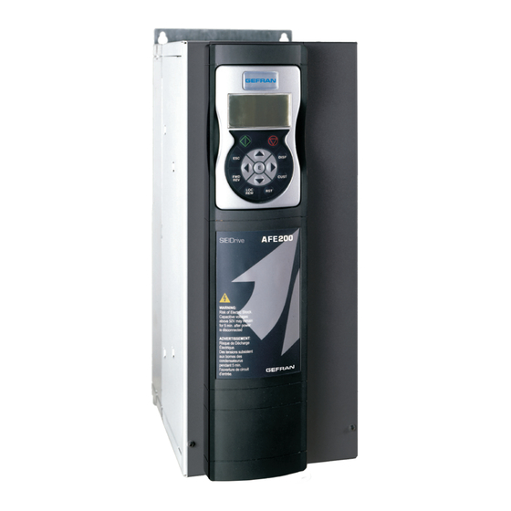
- Page 1 Active Front End Regenerative Power Supply Unit AFE200 AFE200-...-6 Instruction Manual ..
-
Page 2: Information About This Manual
Gefran S.p.A has the right to modify products, data and dimensions without notice. The data can only be used for the product description and they can not be understood as legally stated properties. -
Page 3: Table Of Contents
Table of contents Information about this manual ..........2 1 - Safety Precautions ............... 6 1.1 Symbols used in the manual ..................6 1.2 Safety precaution...................... 7 1.3 General warnings ..................... 7 1.4 Instruction for compliance with UL Mark (UL requirements), U.S. and Canadian electrical codes ....................... - Page 4 6.5 Configuration of the display ..................53 6.5.1 Language selection ....................53 6.5.2 Selection of Easy / Export mode ................53 6.5.3 Startup display .......................53 6.5.4 Back-lighting of the display..................53 6.6 Alarms........................54 6.6.1 Alarm reset ......................54 6.7 Messages ....................... 54 6.8 Saving and recovery of new parameter settings ............ 55 6.8.1 Selection of the keypad memory ................55 6.8.2 Saving of parameters on the keypad..............55 6.8.3 Load parameters from keypad ................56...
- Page 5 Appendix 2 - Parallel connection (400 ... 1000kW sizes) ..170 A 2.1 Introduction......................170 A 2.2 MS-SL interface cable wiring sizes 400...710kW ..........172 A 2.3 MS-SL interface cable wiring sizes 900...1000 kW ........... 173 A 2.4 Jumpers and Switches ..................174 A 2.5 LEDs........................
-
Page 6: Safety Precautions
1 - Safety Precautions 1.1 Symbols used in the manual Indicates a procedure, condition, or statement that, if not strictly observed, could result in personal injury or death. Indique le mode d’utilisation, la procédure et la condition d’exploitation. Si ces consignes ne Warning! sont passtrictement respectées, il y a des risques de blessures corporelles ou de mort. -
Page 7: Safety Precaution
Le système d’actionnement électrique (drive électrique + installation) ne peut être utilisé que dans les conditions d’exploitation et les lieux prévus dans le manuel et uniquement avec les dispositifs et les composants recommandés et autorisés par Gefran. Safety precaution The following instructions are provided for your safety and as a means of prevent- ing damage to the product or components in the machines connected. - Page 8 Only suitable qualified personnel should work on this equipment, and only after becom- ing familiar with all safety notices, installation, operation and maintenance procedures contained in this manual. The successful and safe operation of this equipment is dependent upon its proper handling,installation, operation and maintenance. Seul un personnel dûment formé...
-
Page 9: Instruction For Compliance With Ul Mark (Ul Requirements), U.s. And Canadian Electrical Codes
1.4 Instruction for compliance with UL Mark (UL require- ments), U.S. and Canadian electrical codes Short circuit ratings AFE200 must be connected to a grid capable of supplying a symmetrical short- circuit power of less than or equal to “xxxx A rms (at 480 V +10% V max). The values of the “xxxx”... - Page 10 Solid State Motor Overload Protection. Drive incorporate motor overload protection. Protection is implemented as software function. Instruction manual specify degree of protection and detailed installation instruction.* *Applicable up to 9 May 2013. New requirement. Applicable as from 9 May 2013. AFE200 •...
-
Page 11: Introduction To The Product
2 - Introduction to the product AFE200 is the series of AC/DC Active Front End (AFE) regenerative power sup- ply units With a powerful 32-bit technology platform and reliable IGBT power stage the AFE200 offers significant advantages for single or multi-inverter automation sys- tems powered by a common DC bus. -
Page 12: Drive Type Designation
2.1 Drive type designation The main technical characteristic of the drive are showed in the product code and in the nameplate. AFE200 3 220 -K X X -4 -XX YY Parallel version only: YY : 04 = 400.0 kW XX : MS = MASTER 05 = 500.0 kW SL = SLAVE... -
Page 13: Parallel Inverters
The choice of AFE200 depends on the power rating of the inverters connected to the DC-link. The rated output current of the drive must be higher or equal to the sum of the power ratings of the drives connected to the DC-link. For further information please see Appendix 1. -
Page 14: Transport And Storage
3 - Transport and storage Correct transport, storage, erection and mounting, as well as careful operation and maintenance are essential for proper and safe operation of the equipment. Protect the AFE200 against physical shocks and vibration during transport and storage. Also be sure to protect it against water (rainfall) and excessive temperatures. -
Page 15: Permissible Environmental Conditions
Permissible Environmental Conditions Temperature storage �������������������� -25…+55°C (-13…+131°F), class 1K4 per EN50178 -20…+55°C (-4…+131°F), for devices with keypad transport ������������������� -25…+70°C (-13…+158°F), class 2K3 per EN50178 -20…+60°C (-4…+140°F), for devices with keypad Air humidity storage �������������������� 5% to 95 %, 1 g/m to 29 g/m (class 1K3 as per EN50178) transport �������������������... -
Page 16: Mechanical Installation
4 - Mechanical installation The Drive must be mounted on a wall that is constructed of heat resistant material. While the Drive is operating, the temperature of the Drive’s cooling fins can rise to a temperature of 158° F (70°C). Le drive doit être monté... -
Page 17: Fastening Positions
Fastening positions Fissaggio a muro 311 [12.24”] Wall mounting 190 [7.48”] 268 [10.55”] 220 [8.66”] 187.6 [7.4”] 150 [5.91”] Taglia 5 Taglia 4 Taglia 3 Size 5 Size 4 Size 3 265 [10.43”] 267 [10.51”] 421 [16.57”] Fissaggio a muro Wall mounting 275 [10.83”] 175 [6.89”]... - Page 18 [16.42”] 355.6 [140”] 177.8 [7.00”] Fissaggio a muro Wall mounting (*) Protezione in policarbonato trasparente (*) Protective trasparent policarbonate [0.26”] Taglia 7 Size 7 [0.26”] 17.45 [0.69”] Taglie 1-2-3 Taglia 4 Sizes 1-2-3 Size 4 [0.21”] [0.26”] 12.5 [0.26”] [0.49”] [0.21”] Taglia 5 Taglia 6...
- Page 19 [16.42”] [16.42”] 355.6 355.6 [140”] [140”] 177.8 177.8 [7.00”] [7.00”] Fissaggio a muro Wall mounting 400 ... 710 kW (*) Protezione in policarbonato trasparente (*) Protective trasparent policarbonate [16.42”] [16.42”] [16.42”] 355.6 355.6 355.6 [140”] [140”] [140”] 177.8 177.8 177.8 [7.00”] [7.00”] [7.00”]...
- Page 20 [0.26”] [0.26”] 17.45 [0.69”] Recommended screws for fastening AFE200-72000-KXX-4-MS 04 400kW AFE200-72000-XXX-4-SL AFE200-72500-KXX-4-MS 05 500kW AFE200-72500-XXX-4-SL 12 x M6 x 16 mm screws + Grover (spring-lock) washer + Flat washer AFE200-73150-KXX-4/4A-MS 06 630kW AFE200-73150-XXX-4/4A 4-SL AFE200-73550-KXX-4/4A-MS 07 710kW AFE200-73550-XXX-4/4A-SL AFE200-73150-KXX-4/4A-MS 09 AFE200-73150-XXX-4/4A-SL 900kW AFE200-73150-XXX-4/4A-SL...
-
Page 21: Wiring Procedure
5 - Wiring Procedure Adjustable frequency drives are electrical apparatus for use in industrial installations. Parts of the Drives are energized during operation. The electrical installation and the opening of the device should therefore only be carried out by qualified personnel. Im- Warning! proper installation of motors or Drives may therefore cause the failure of the device as well as serious injury to persons or material damage. - Page 22 - the output cables are less than 50m (screened) or 100m (unscreened). RCD: Residual Current Device RCCB: Residual Current Circuit Breaker ELCB: Earth Leakage Circuit Breaker Note: The residual current operated circuit-breakers used must provide protection against direct-current components in the fault current and must be suitable for briefly suppressing power pulse current peaks.
- Page 23 that have been stored for long periods, connect them to a power supply for two hours with no load connected in order to regenerate the capacitors, (the input voltage has to be applied without enabling the drive). En cas de stockage des variateurs pendant plus de deux ans, il est conseillé de contrôler l’état des condensateurs CC avant d’en effectuer le branchement.
-
Page 24: Power Section
5.1 Power section 5.1.1 Cable Cross Section Terminals: C - D - U - V - W Sizes Maximum Cable Cross Section (flexible conductor) Recommended stripping Tightening torque (min) AFE200- (mm) (Nm) 3220 1,5 ... 1,7 4450 2,4 ... 4,5 5900 61320 Bars: C - D - U - V - W... -
Page 25: Emc Guide Line
73550-KXX-4/4A-MS 07 2 x 185 2 x kcmil 350 / 75 (U,V,W=M12) (M10) (M12) 710kW 73550-XXX-4/4A-SL 2 x 185 2 x kcmil 350 / 75 (U,V,W=M12) (M10) (M12) 73150-KXX-4/4A-MS 09 2 x 185 2 x kcmil 350 / 75 (U,V,W=M12) (M10) (M12) 73150-XXX-4/4A-SL... - Page 26 Note! For further information regarding electro-magnetic compatibility standards, according to Directive 89/336/EEC, conformity checks carried out on Gefran appliances, connection of filters and mains inductors, shielding of cables, ground connections, etc., consult the “Electro-magnetic compatibility guide” on the CD attached to this drive.
-
Page 27: Block Diagram Power Section
5.1.3 Block diagram power section AFE200-3220 ... 73550 DC LINK AFE200 : 400kW - 710kW Input choke Input (mandatory) fuse ADV- ...- MS.. DC LINK Input choke Input ADV- ...- SL.. (mandatory) fuse DC LINK AFE200 : 900kW - 1MW Input choke Input (mandatory) -
Page 28: Power Line Connection
5.1.4 Power line connection AFE200-3220 ... 4450 L1 L2 L3 BR1 BR2 Regen choke (Mandatory) EXP-SYNC-ADV card on SLOT2 Voltage R2 S2 T2 Sense T’ Precharge Kit S’ (Mandatory) R’ R1 S1 T1 FILTER 3ph - 380 V / 480 50/60 Hz (AFE200-...-4) 3ph - 380 V / 480... - Page 29 AFE200-71600 ... 73550 Regen choke (Mandatory) EXP-SYNC-ADV card on SLOT2 Voltage Sense T’ Precharge Kit S’ (Mandatory) R’ R1 S1 T1 FILTER 3ph - 380 V / 480 50/60 Hz (AFE200-...-4/4A) 3ph - 380 V / 480 50/60 Hz (AFE200-...-6/6A) AFE200 : 400kW - 710kW AFE200-...-MS-..
-
Page 30: Dc Output Connection
AFE200 : 900kW - 1MW AFE200-...-SL-.. AFE200-...-MS-.. AFE200-...-SL-.. Regen choke Regen choke Regen choke (Mandatory) (Mandatory) (Mandatory) EXP-SYNC-ADV card on SLOT2 Voltage Sense T’ T’ T’ Precharge Kit Precharge Kit Precharge Kit S’ S’ S’ (Mandatory) (Mandatory) (Mandatory) R’ R’ R’... - Page 31 AFE200-5900 ... 61320 Common DC bus L1 L2 L3 BR1 BR2 DC FUSES DC output - 650...780 V AFE200 ADV200-DC AFE200-71600 ... 73550 Common DC bus DC FUSES DC output - 650...780 V AFE200 ADV200-DC AFE200 : 400kW - 710kW Common DC bus DC FUSES DC output - 650...780 V...
-
Page 32: Connection Of Fans Power Suplly
5.1.6 Connection of fans power suplly Sizes AFE200- 3220 ... 61320 No connection is necessary: the drive’s internal power supply unit powers the fan (+24Vdc). Terminals Sizes AFE200- 1 x 230V / 50/60Hz, 3,5Arms Ground 250V/10A contact (*) 71600 ... 72500 Power the internal fan (max 600W) with a single-phase voltage on terminals U3/V3. -
Page 33: Regulation Section
5.2 Regulation section 5.2.1 Removing the terminal cover When removing the covers be carefull to lateral metal sheet enclosure. Presence of sharp edge are possible. Warning! 5.2.2 Cable Cross Section Maximum Cable Cross Section Recommended stripping Tightening torque (min) (min) Terminal strips (AWG) (mm) - Page 34 Table 5.2.3.1: Regulation terminals Strip T2 (top) Terminal Designation Function COM Digital output 2 Common reference for digital output 2 (Relay 2) Digital output 2 Programmable digital relay output 2 (NO). Default = Drive ready (PAR 1064) 250 V - 30 V / 2A Analog output 1 Analog output 1.
-
Page 35: Switches, Jumpers And Led
It is not suitable to power supply the regulation card only through a unique rectifier and capacitive filter. La tension de + 24Vdc utilisée pour alimenter extérieurement la carte de régulation doit être stabiliséeet avec une tolérance de ±10% ; absorption maximum de 1A. Les alimentations obtenues avec les seules redresseur e filtre capacitive ne sont pas appropriées. - Page 36 +24 V R-ADV-AFE board To Expansion Cards +24 V Analog input 1 Analog output 1 Analog input 2 Analog output 2 +10V +24V Digital input E mon - 10V Precharge fbk src Precharge Command Digital output 1 (Relay 1) Drive ready Digital output 2 (Relay 2) Drive OK...
- Page 37 +24V OUT +24V OUT +24V OUT Enable Enable Enable Dig.inp E Dig.inp E Dig.inp E Precharge fbk Precharge fbk Precharge fbk Dig.inp 1 Dig.inp 1 Dig.inp 1 Dig.inp 2 Dig.inp 2 Dig.inp 2 Dig.inp 3 Dig.inp 3 Dig.inp 3 Dig.inp 4 Dig.inp 4 Dig.inp 4 Dig.inp 5...
-
Page 38: Serial Interface (Xs Connector)
5.3 Serial interface (XS connector) Funzione Interfaccia elettr. PIN 1 Uso interno – – PIN 2 Uso interno – – PIN 3 RxA/TxA RS485 PIN 4 Equipotenzialità (opzionale) – – PIN 5 0V (Ground for 5 V) – Alimentazione PIN 6 +5 V –... - Page 39 RS485 (XS) Industrial PC Shielded cable with connectors, (with RS485) 5 mt (8S8F59) RS485 (XS) RS232 RS485 Shielded cable with connectors, PCI-COM (S5T60) 5 mt (8S8F59) RS485 (XS) RS232 Shielded cable with RS232 RS485 connectors, 5 mt (8S8F59) PCI-COM (S5T60) USB RS232 converter (S5A20) Kit (S50T6) = Shielded cable 5 mt + PCI-COM...
-
Page 40: Drive / Rs485 Port Point-To-Point Connection (With Insulation)
5.3.2 Drive / RS485 port point-to-point connection (with insulation) To make the connection with galvanic isolation, the OPT-RS485-ADV optional card is required. The card is equipped with a 9-pin D-SUB male connector which must be inserted in the XS connector of the AFE200 drive. Connect terminals 1, 2 and 4 to the serial line as shown in the figure below;... -
Page 41: Typical Connection Diagrams
5.4 Typical connection diagrams AFE200 • Instruction Manual... - Page 42 AFE200 • Instruction Manual...
-
Page 43: Pre-Charge Kit
5.5 Pre-charge kit The pre-charge kit (mandatory) is not included in the AFE200 order code and must be ordered separately. Sizes Type Code AFE200- 3220-4 PRE CHARGE KIT-AFE-022-4 S726391 4450-4 PRE CHARGE KIT-AFE-045-4 S726392 5900-4 PRE CHARGE KIT-AFE-132-4 S726401 61320-4 PRE CHARGE KIT-AFE-132-4 S726401 71600-4... -
Page 44: Fuses For The "Voltage Sense" Connection (F2)
5.5.1 Fuses for the “Voltage sense” connection (F2) The fuses shown are included as standard with the pre-charge kit. Sizes F2 - External fuses for the “Voltage sense” connection AFE200- Type Code 3220 ... 1MW -4/4A 3 x KTK 600V / 0.5A S831B 3220 ... -
Page 45: Pre-Charge Kit Dimensions
5.5.2 Pre-charge kit dimensions Figure 5.5.1 : Pre-charge kit for AFE200-3220...4450 Dimension in mm Figure 5.5.2 : Pre-charge kit for AFE200-5900...61320 AFE200 • Instruction Manual... - Page 46 VEDI DETTAGLIO Dimension in mm 160.5 VEDI DETTAGLIO 15.5 DETTAGLIO SCALA 3:5 DETTAGLIO SCALA 3:5 Figure 5.5.3 : Pre-charge kit for AFE200-71600 VEDI DETTAGLIO Dimension in mm 160.5 15.5 DETTAGLIO DETTAGLIO SCALA 3:5 SCALA 3:5 Figure 5.5.4 : Pre-charge kit for AFE200-72000 ...1MW AFE200 •...
- Page 47 VEDI DETTAGLIO Dimension in mm 160.5 VEDI DETTAGLIO 15.5 DETTAGLIO SCALA 3:5 DETTAGLIO SCALA 3:5 Figure 5.5.5 : Pre-charge kit for AFE160 ...1MW - 690V AFE200 • Instruction Manual...
-
Page 48: Use Of The Keypad
6 - Use of the keypad This chapter describes the keypad and methods of use for display and program- ming of AFE200 parameters. 6.1 Description LCD display led is lit 7 virtual leds line: ILim led is off 01 MONITOR 02 DRIVE INFO Four alphanumeric lines 03 STARTUP WIZARD... -
Page 49: Navigation
LED’s meaning: the LED is lit, when the drive operates with a positive torque the LED is lit, when the drive operates with a negative torque the LED is lit, when the drive is enabled The led is lit when the drive is in local mode and OFF when in remote mode. -
Page 50: Scanning Of The Parameters
Depends on the type of parameter: ● Numeric parameter: displays the numeric value of the parameter, in the format required, and unit of measurement (figure A). ● Binary selection: the parameter may assume only 2 states, indicated as OFF-ON or 0 - 1 (figure B). ●... -
Page 51: Parameter Modification
of the parameter (PAR). When the parameter reached by the “Goto” command is displayed, it is possible to navigate all the parameters forming part of the same group using the ▲ and ▼ keys. Pressing the ► key returns to the “Goto” function. To exit the “Goto”... -
Page 52: How To Save Parameters
● LINK type parameter The parameter may assume the number of another parameter as value. ILim 0 5 . 0 4 PA R : 6 0 8 DC volta g e ref src Test g en out Value: 5008 ILim ILim ILim 0 5 . -
Page 53: Configuration Of The Display
Configuration of the display 6.5.1 Language selection Menu 04 DRIVE CONFIG, parameter 04.17 Language select, PAR: 578, default=English. Used to set one of the languages available : English, Italian, Francais, Deutsch, Polish, Romanian, Russian, Turkish and Portuguese. ILim ILim ILim 0 4 . -
Page 54: Alarms
Menu 04 DRIVE CONFIG, parameter 04.16 Display backlight, PAR : 576. Sets lighting of the display the light of the display remains always on. (default) the light switches off after approx. 3 minutes from pressing of the last key. 6.6 Alarms The alarms page is displayed automatically when an alarm occurs. -
Page 55: Saving And Recovery Of New Parameter Settings
ILim Message Load default Code: 0001H-1 Press ESC to exit MESSAGE : identifies a message. xx indicate show many messages are enqueued. The queue may contain a maximum of 10 messages and the message with the highest number is the most recent. -
Page 56: Load Parameters From Keypad
If an error occurs during transfer, the following message is displayed: ILim Message Save par failed Code: Press ESC to exit The code XX indicates the type of error, see paragraph 9.2. To exit from the error message, press the ESC key. 6.8.3 Load parameters from keypad Menu 04 DRIVE CONFIG, parameter 04.20 Load par from keypad, PAR : 592. -
Page 57: Commissioning Via Keypad
7 - Commissioning via keypad Adjustable frequency drives are electrical apparatus for use in industrial installations. Parts of the Drives are energized during operation. The electrical installation and the opening of the device should therefore only be carried out by qualified personnel. Im- Warning! proper installation of motors or Drives may therefore cause the failure of the device as well as serious injury to persons or material damage. - Page 58 According to the EEC standards the AFE200 and accessories must be used only after checking that the machine has been produced using those safety devices required by the 89/392/EEC set of rules, as far as the machine industry is concerned. These stand- ards do not apply in the Americas, but may need to be considered in equipment being shipped to Europe.
- Page 59 des explosions. Les drives doivent être installés loin des zônes dangeureuses, et équipés de moteurs appropriés. Protect the device from impermissible environmental conditions (temperature, humidity, shock etc.). Protéger l’appareil contre des effets extérieurs non permis (température, humidité, chocs etc.). Caution To the output of the drive (terminals C, D): - the direct connection of the inputs and outputs (bypass) are not permissible.
-
Page 60: Startup Wizard
7.1 Startup Wizard Introduction The startup wizard is a guided procedure used for quick start-up of the drive that helps to set the main parameters. It consists of a series of questions relating to the various sequences for entering and calculating the parameters necessary for correct drive operation. The order of these sequences is as follows: ●... - Page 61 Note ! In the procedures described below, the settings have been made using the AFE200-4450 drive. Step 1 - Connections Connect the power supply line and enabling contacts as shown in the diagram in chapter 5.4.1. Checks to be performed before powering the drive •...
- Page 62 ILim ILim ILim ILim ILim STARTUP WIZARD S E Q . 0 1 PA R : 6 0 0 1 3 . 0 1 S E Q . 0 1 PA R : PA R : 6 0 0 1 0 0 S E Q .
-
Page 63: Programming
7.2 Programming 7.2.1 Menu display modes The programming menu can be displayed in two modes, which can be selected using the Access mode parameter (04 - DRIVE CONFIG menu), see chapter 6.5.2: • Easy (default) only the main parameters are displayed. •... - Page 64 Practical example The following examples illustrate the philosophies and methods with which more or less complex operations are performed in the single “function blocks”, the results of which represent the output of the block. • Example: Inverting the analog reference signal To invert the “Analog input 1 Block”...
-
Page 65: Description Of Parameters And Functions (Expert List)
8 - Description of parameters and functions (Expert list) Legend Menu Description Type FB BIT 1 - MONITOR ( Level 1 menu ) Output current FLOAT 16/32 Output voltage FLOAT 16/32 13.2 - FUNCTIONS/DOUBLE PAR SET ( Level 2 menu ) 13.2.1 3300... - Page 66 1 - MONITOR The monitor menu displays the measured values of the sizes and of the drive operating parameters. Menu Description Type FB BIT Output current FLOAT 16/32 The drive output current is displayed. Menu Description Type FB BIT Output voltage FLOAT 16/32 The drive line voltage output is displayed.
- Page 67 The reactive current reference is displayed. Menu Description Type FB BIT Active current FLOAT 16/32 The active current value currently in use is displayed. Menu Description Type FB BIT Reactive current FLOAT 16/32 The reactive current value currently in use is displayed. Menu Description Type...
- Page 68 Menu Description Type FB BIT 1.17 1066 Enable state mon The drive Enable command status is displayed. Voltage must be present on terminal 7. The FR Forwardstart command is needed to start the AFE200. Disabled drive disabled Enabled drive enabled Menu Description Type...
- Page 69 000000000011 Active DI 2 Active DI 1 Menu Description Type FB BIT 1.21 1400 Digital output X mon UINT16 The status of the digital outputs of the expansion card is displayed. It can also be read via a serial line or fieldbus. The data are contained in a word, where each bit is 1 if voltage is supplied to the corresponding input terminal.
- Page 70 2 - DRIVE INFO This menu displays the information for identifying and configuring the drive. Menu Description Type FB BIT Drive size UINT16 The drive size identification code is displayed. Menu Description Type FB BIT Drive family ENUM No Power The available mains voltage is displayed (e.g.
- Page 71 Menu Description Type FB BIT Application ver.rel UINT16 The version number and release number of the application are displayed. Menu Description Type FB BIT Application type UINT16 The type of application currently used by the drive is displayed. Menu Description Type FB BIT Time drive power on...
- Page 72 2.19 Slot3 card type ENUM None The type of expansion card installed in the relative slot of the drive is displayed. None I/O 1 1793 I/O 2 2305 I/O 3 3329 I/O 4 Can/Dnet Profibus Gdnet Fast IO Unknown Menu Description Type FB BIT...
- Page 73 3 - STARTUP WIZARD The startup wizard menu suggests a procedure for commissioning the drive quickly with a reduced number of settings. Advanced customization requires the use of the single parameters relating to the specific performance levels. See the procedure described in the previous Startup wizard chapter. AFE200 •...
- Page 74 4 - CONFIG DRIVE Menu Description Type FB BIT Save parameters Any changes to parameter values immediately affect drive operations, but are not automatically saved in the permanent memory. The “Save Parameters” command is used to save current parameter values in the permanent memory.
- Page 75 Required Done The parameter displays the Required message when the motor parameters that have been entered need to be saved. When they have been saved the parameter indicates Done. Menu Description Type FB BIT Application select ENUM None ERWZ Selection of which IEC 61131-3-compliant application to make operational. None Application 1 Application 2...
- Page 76 8 kHz 10 kHz 12 kHz 16 kHz Menu Description Type FB BIT 4.11 Ambient temperature ENUM 40 degC ERWZ Setting of the ambient temperature value. This parameter is used to set the output cur- rent derating factor (1% for every °C above 40°C). 40 degC 50 degC 40 degC...
- Page 77 Menu Description Type FB BIT 4.14 Startup display INT16 20000 ERW It is possible to set the parameter that will automatically be displayed when the drive is switched on. If set to -1 the drive moves to the display menu. Menu Description Type...
- Page 78 5 - REFERENCE AFE drives have a DC-link voltage regulation circuit; which can be adapted to suit the various appli- cations. In the standard version, the regulator has PI behaviour and the regulator parameters are the same for the entire field of regulation. Menu Description Type...
- Page 79 6 - COMMANDS It is possible to work in Local or Remote mode. When switching between Remote and Local modes the origin of the Enable and Start commands is switched. In Remote mode the “Commands remote sel” parameter is used to configure the source of the Enable and Start commands which can be Terminal (standard digital input, expansion digital input) or Digital (Modbus, Fieldbus).
- Page 80 Example 2 With the machine controlled from console A, the drive operates in Local -> Terminal -> Standard digital input mode. With the machine controlled from console B, the drive operates in Remote ->Digital -> Expansion digital input mode. When switching the control console, the drive must switch between Remote and Local mode. The switch command must be sent via Standard digital input or Expansion digital input.
- Page 81 Inactive EmgStop&Alarm If the command is set to Inactive, pressing the Stop key on the keypad is ineffective. If the command is set to EmgStop&Alarm, pressing the Stop key disables the drive and the Emg stop alarm is generated. The drive is automatically disabled and waits for the Alarm reset command (RST key, see chapter 6.6.1).
- Page 82 Menu Description Type FB BIT 1018 Digital Enable src LINK 6000 16384 ERW L�DIGSEL2 Selection of the origin (source) for the Digital Enable signal. The signal to be associ- ated with this function can be selected from the “L_DIGSEL2” selection list. Menu Description Type...
- Page 83 7 - DIGITAL INPUTS Menu Description Type FB BIT 1132 Dig inp 1 inversion 1134 Dig inp 2 inversion AFE200 • Instruction Manual...
- Page 84 1136 Dig inp 3 inversion 1138 Dig inp 4 inversion 1140 Dig inp 5 inversion Reversal of the logic status of the function associated with the digital input (e.g. from enabled with +24V signal to enabled with low signal). Menu Description Type FB BIT...
- Page 85 8 - DIGITAL OUTPUTS AFE200 • Instruction Manual...
- Page 86 Menu Description Type FB BIT 1310 Digital output 1 src LINK 1122 16384 1312 Digital output 2 src LINK 1064 16384 1314 Digital output 3 src LINK 1062 16384 1316 Digital output 4 src LINK 6000 16384 L�DIGSEL1 Selection of the origin (source) of the signal to be assigned to the relative digital output.
- Page 87 9 - ANALOG INPUTS Menu Description Type FB BIT 1500 Analog input 1 mon INT16 16/32 9.17 1550 Analog input 2 mon INT16 16/32 The value of the voltage on the output of the function block of the relative analog input is displayed.
- Page 88 9.18 1552 Analog inp 2 type ENUM -10V..+10V Selection of the type of input (voltage or current). Depending on the input signal, move the switches on the regulation card. The factory parameter is inputs set for differential voltage signals (± 10V). -10V..+10V 0.20mA ...
- Page 89 command is sent, An inp x offset tune is automatically selected so that the available input signal corresponds to the zero value of the variable. Offset tuning can also be performed with the drive enabled. Automatic tuning can only be performed if the fol- lowing condition is present: Automatic tuning can only be performed if the following condition is present: - Input voltage less than 1V or input current less than 2 mA...
- Page 90 Menu Description Type FB BIT 1514 Analog inp 1 bottom INT16 -16384 -32768 +32767 ERW 9.24 1564 Analog inp 2 bottom INT16 -16384 -32768 +32767 ERW Setting of the lower speed reference limit as a function of the voltage (or current) of the relative analog reference..
- Page 91 x = 1, 2 Analog inp x thr Analog inp x <thr x = 1, 2 Analog inp x thr Analog inp x <thr Menu Description Type FB BIT 9.12 1522 An inp 1 deadband perc FLOAT 100.0 9.28 1572 An inp 2 deadband perc FLOAT...
- Page 92 AnInp Drive 100% -10V Par.1522=50% -100% AnInp Terminal Par.1522=50% 100% -100% Menu Description Type FB BIT 9.13 1524 An inp 1 alt value INT16 16/32 -16384 16384 ERW 9.29 1574 An inp 2 alt value INT16 16/32 -16384 16384 ERW Setting of a fixed alternative value for the relative analog input, which can be selected via a command enabled by a digital input programmed with the An inp alt sel src parameter.
- Page 93 Menu Description Type FB BIT 9.33 1600 Analog input 1X mon INT16 16/32 9.44 1650 Analog input 2X mon INT16 16/32 The value of the voltage output of the function block of the relative analog input is displayed. Menu Description Type FB BIT 9.34...
- Page 94 Menu Description Type FB BIT 9.36 1606 An inp 1Xoffset tune 9.47 1656 An inp 2Xoffset tune Self-tuning command for the offset of the relative analog input of the expansion card. Automatic fine tuning of the input. To perform self-tuning, set the input signal to its minimum value and execute the command.
- Page 95 Menu Description Type FB BIT 9.39 1614 Analog inp 1X bottom INT16 -16384 -32768 +32767 ERW 9.50 1664 Analog inp 2X bottom INT16 -16384 -32768 +32767 ERW Setting of an offset value to algebrically add to the relative analog input of the expan- sion card.
- Page 96 Menu Description Type FB BIT 9.43 1632 Dest ing analogico1X ILINK 9.54 1682 Dest ing analogico2X ILINK The function for which the relative analog input of the expansion card has been pro- grammed and on which it acts is displayed. AFE200 •...
- Page 97 10 - ANALOG OUTPUTS On the AFE200 regulation card there are two programmable analog outputs. Analog output 1 supplies a two-pole +/-10VDC voltage signal, while analog output 2 can be program- med to obtain a 0-20mA or 4-20mA output signal in current or a signal in two-pole +/-10VDC voltage, depending on the parameter assigned.
- Page 98 1500 Analog input 1 mon 1550 Analog input 2 mon 10V = 10V Analog input 1600 Analog input 1X mon 1650 Analog input 2X mon Drive overload accum 5V = 100% Accumulator 4024 … 4174 Fieldbus M->SX mon 10V = 16384 * 2^16 3700 …...
- Page 99 Example of calculation of scale factor Analog out x scale : To display the drive speed, use an analog instrument with field of measurement from 0...2V. This means that, to display the speed of the drive, a voltage of 2V on the ana- log output of the drive must correspond to the maximum speed.
- Page 100 Select option 1 in order to apply a maximum voltage of +10V or a signal in current of 0 ... 20 mA to analog output 2. The signal must be positive. Select option 2 to apply a signal in current of 4...20 mA to analog output 2. Menu Description Type...
- Page 101 Menu Description Type FB BIT 10.18 1866 Analog out 1X mon INT16 The actual value of the voltage present on analog output 1 of the expansion card is displayed. Menu Description Type FB BIT 10.19 1868 Analog out 2X mon INT16 The actual value of the voltage or current present on analog output 2 of the expansion card is displayed.
- Page 102 11 - REGULATOR PARAM Menu Description Type FB BIT 11.1 2250 Current reg P gain FLOAT CALCF ERWS Setting of the proportional coefficient of the current regulator. Menu Description Type FB BIT 11.2 2252 Current reg I time FLOAT CALCF ERWS Setting of the integral coefficient of the current regulator.
- Page 103 The dead time compensation function (Dead time compensation), compensates the distortion of output voltage caused by the voltage drop on the IGBT devices and their switching characteristics. Menu Description Type FB BIT 11.5 2280 Dead time limit FLOAT SIZE 50.0 ERWS Setting of the dead time voltage compensation value.
- Page 104 12 - ACTIVE CURR CONFIG Menu Description Type FB BIT 12.1 2350 Active curr lim Pos FLOAT 16/32 CALCF CALCF ERWS Setting of the drive active current limit for the positive current direction. Menu Description Type FB BIT 12.2 2352 Active curr lim Neg FLOAT 16/32...
- Page 105 torque Torque curr lim Pos Torque curr lim Pos speed Torque curr lim Neg Torque curr lim Neg Menu Description Type FB BIT 12.4 2358 Active curr lim src LINK 16/32 6000 16384 ERWZ L�LIM Selection of the origin (source) to be used to set the active current limit. The signals that can be associated with the function can be selected from the “L_LIM”...
- Page 106 13 - FUNCTIONS 13.1 - Reserved for AFE200-PV. 13.2 - FUNCTIONS/DOUBLE PAR SET Two independent sets of parameters can be stored in the AFE200 drive. These can be selected via the keypad or by using an external command. This makes it possible to change all the drive parameters quickly and automatically according to the various operating requirements.
- Page 107 Menu Description Type FB BIT 13.2.3 3304 Par set select mon ENUM Set 0 The parameter set currently in use is displayed. Set 0 Set 1 Menu Description Type FB BIT 13.2.4 3306 Par set 0 to 1 copy Procedures for setting up and managing the double parameter set Creating the second set: This function copies parameter set 0 onto set 1.
- Page 108 13.3 - FUNCTIONS/COMPARE This function allows the comparison among two signals or values. Menu Description Type FB BIT 13.3.1 3650 Dig compare input 1 perc FLOAT -100.0 100.0 Setting of the digital value of the first element of comparison. Menu Description Type FB BIT...
- Page 109 Ingr1!=Ingr2 Ingr1<Ingr2 Inrg1>Ingr2 |Ing1|=|Ing2| |Ing1|!=|Ing2| |Ing1|<|Ing2| |Ing1|>|Ing2| If set to 0 the comparator is not enabled If set to 1 the comparator output is enabled when the value of Dig compare input 1 is inside the window resulting from the value of Dig compare input 2 ± the tolerance set via the Comparator Window.
- Page 110 13.4 - FUNCTIONS/PADS The general variables are used to exchange data between the various components of a Bus system. They are similar to the variables of a PLC. The basic structure of the system is illustrated below. Pads can be used, for example, to send information from a fieldbus to an optional card. All Pads can be read and written.
- Page 111 14 - COMMUNICATION The AFE200 drive is provided with a standard port (9 pole sub-D connector: XS) for connecting the RS485 serial line used for drive-PC point-to-point communication (via the GF-eXpress configuration software) or for the multidrop connection. The RS485 serial line format is: 8 data bits, no parity and one stop bit. 14.1 - COMMUNICATION/RS485 Menu Description...
- Page 112 concerns the use of the standard RS485 serial line. Example: if the delay in Tx/Rx switching on the master is a maximum of 20ms, the Ser answer delay parameter must be set to at least 20ms: 22ms Menu Description Type FB BIT 14.1.6 3808...
- Page 113 Menu Description Type FB BIT 14.2.4 4010 Fieldbus M->S enable ENUM Enable ERWZ Setting of fieldbus data updating. Disable Enable If set to 0, the possibility of sending commands and references from the drive PLC via the fieldbus is disabled. If set to 1 the possibility of sending commands and references from the drive PLC via the fieldbus is enabled.
- Page 114 14.3.29 4090 Fieldbus M->S8 ipa FBM2SIPA 14.3.33 4100 Fieldbus M->S9 ipa FBM2SIPA 14.3.37 4110 Fieldbus M->S10 ipa FBM2SIPA 14.3.41 4120 Fieldbus M->S11 ipa FBM2SIPA 14.3.45 4130 Fieldbus M->S12 ipa FBM2SIPA 14.3.49 4140 Fieldbus M->S13 ipa FBM2SIPA 14.3.53 4150 Fieldbus M->S14 ipa FBM2SIPA 14.3.57 4160 Fieldbus M->S15 ipa...
- Page 115 Par 32 If set to 0 the channel is not assigned. If set to 1 the datum is assigned a 16-bit count. If set to 2 the datum is assigned a 32-bit count. If set to 3 16 bits on the channel are reserved for the datum, not used. If set to 4 32 bits on the channel are reserved for the datum, not used.
- Page 116 16_H Receives 16 bits from FB and copies to 16H bit of monitor. OK 16_L Receives 16 bits from FB and copies to 16L bit of monitor. OK A Fieldbus M->S X Mon parameter can only be assigned to a single “src”. If assigned to more than one src, an error signal is generated during fieldbus initialization.
- Page 117 14.4.29 4250 Fieldbus S->M8 ipa FBM2SIPA 20000 14.4.33 4260 Fieldbus S->M9 ipa FBM2SIPA 20000 14.4.37 4270 Fieldbus S->M10 ipa FBM2SIPA 20000 14.4.41 4280 Fieldbus S->M11 ipa FBM2SIPA 20000 14.4.45 4290 Fieldbus S->M12 ipa FBM2SIPA 20000 14.4.49 4300 Fieldbus S->M13 ipa FBM2SIPA 20000 14.4.53 4310...
- Page 118 If set to 2 the datum is assigned a 32-bit count. If set to 3 16 bits on the channel are reserved for the datum, not used. If set to 4 32 bits on the channel are reserved for the datum, not used. If set to 5 the datum is assigned a 16-bit count used by MDPLC.
- Page 119 14.4.8 4196 Fieldbus S->M2 mul FLOAT 1000.0 ERW 14.4.12 4206 Fieldbus S->M3 mul FLOAT 1000.0 ERW 14.4.16 4216 Fieldbus S->M4 mul FLOAT 1000.0 ERW 14.4.20 4226 Fieldbus S->M5 mul FLOAT 1000.0 ERW 14.4.24 4236 Fieldbus S->M6 mul FLOAT 1000.0 ERW 14.4.28 4246 Fieldbus S->M7 mul FLOAT...
- Page 120 14.5.14 4426 Word bit13 src LINK 6000 16384 ERW 14.5.15 4428 Word bit14 src LINK 6000 16384 ERW 14.5.16 4430 Word bit15 src LINK 6000 16384 ERW L�DIGSEL1 Selection of the origin (source) of the signal to be used for coding in Word comp. This function allows the user to compose a single word composed of 16 signals, each of which can be selected from among those listed in the “L_DIGSEL1”...
- Page 121 14.6 - COMMUNICATION/WORD DECOMP Menu Description Type FB BIT 14.6.1 4450 Dig word decomp UINT32 Setting of the digital input decoded by the “Word decomp” block. Menu Description Type FB BIT 14.6.2 4452 Word decomp src LINK 4450 16384 ERW L�WDECOMP Selection of the origin (source) of the word to be decoded by the “Word decomp”...
- Page 122 15 - ALARM CONFIG In the ALARM CONFIG menu the type of effect any alarm signals have on the AFE product is determi- ned: - The alarm status is saved - How must the AFE product react to the alarm signal? - Auto restart - Alarm reset For some alarms, behaviour can be configured separately for each signal, while for the others the...
- Page 123 Menu Description Type FB BIT 15.1 4500 Fault reset src LINK 16BIT 1120 16384 DIGSEL2 Selection of the origin (source) of the signal to be used for the command to reset the AFE product after an alarm. The terminal that can be used for this function can be selected from among those listed in the “L_DIGSEL2”...
- Page 124 bling of the alarm. If an alarm condition occurs, the AFE product will wait for the set time to activate the alarm. If the alarm is removed within the set time, the AFE product will not indicate any alarm condition. Menu Description Type...
- Page 125 This alarm indicates that the AFE product overload threshold has been reached. Ignore Warning Disable Menu Description Type FB BIT 15.15 4582 HTsens restart ENUM Disable Enabling of automatic restart after the AFE product heatsink overtemperature alarm HeatsinkS OTUT [12]. Disable Enable Menu...
- Page 126 Enabling of automatic restart after the desaturation alarm Desaturation [5]. This alarm indicates a short circuit between the phases of the power bridge. Disable Enable Menu Description Type FB BIT 15.22 4612 Desat restart time UINT16 2000 1000 10000 ERW Setting of the time within which the Desaturation [5] alarm must be reset in order to perform automatic restart.
- Page 127 Menu Description Type FB BIT 15.29 4650 UVRep attempts UINT16 1000 Setting of the maximum number of attempts at automatic restart after the Undervolt- age [2] alarm before a Mult Undervoltage [6] alarm is generated. If this parameter is set to 1000 an infinite number of attempts are available. Menu Description Type...
- Page 128 External fault Emg stop alarm Power down Prc fbk loss Not Used1 Not Used2 Not Used3 Not Used4 Not Used5 Not Used6 Not Used7 Not Used8 Not Used9 Plc1 fault Plc2 fault Plc3 fault Plc4 fault Plc5 fault Plc6 fault Plc7 fault Plc8 fault Menu...
- Page 129 16 - ALARM LOG This is the menu in which the log of previous alarms is saved, with the time the alarm occurred (in relation to the Time drive power on parameter). The alarms are displayed starting from the most recent (No. 1) up to the furthest back in time (No. 30). Up to 30 alarm signals can be displayed.
- Page 130 17 - PLC LOG Reserved for AFE200-PV. 18 - APPLICATION This menu is designed to host two applications (e.g. PID control, etc.) using the MDPlc program, currently in progress. It will not be possible to use both applications simultaneously. PAR 558 Applica- tion select parameter in the DRIVE CONFIG menu must be used to select between the two possible applications.
-
Page 131: Parameters On Selection Lists, But Not Displayed On Keypad
8.1 Parameters on selection lists, but not displayed on keypad Menu Description Type FB BIT Drive overload trip 16BIT This signal indicates that the AFE product is in the overload alarm condition. Menu Description Type FB BIT Drive overload 80% 16BIT This signal indicates that the AFE product has reached 80% of the thermal image ac- cumulator (Drive overload). - Page 132 indicates the end of pre-loading. It is used to close the main contactor and open the pre-load resistor contactor. Menu Description Type FB BIT 1210 Digital input 1X mon 16BIT 1212 Digital input 2X mon 16BIT 1214 Digital input 3X mon 16BIT 1216 Digital input 4X mon...
- Page 133 This signal is activated when the alarm configured in parameter 4704 alarm dig sel 3 is active. Menu Description Type FB BIT 4714 Alm dig out mon 4 16BIT This signal is activated when the alarm configured in parameter 4706 alarm dig sel 4 is active.
- Page 134 with the internal PLC Description 1 = PLC 1 fault active 1 = PLC 2 fault active 1 = PLC 3 fault active 1 = PLC 4 fault active 1 = PLC 5 fault active 1 = PLC 6 fault active 1 = PLC 7 fault active 1 = PLC 8 fault active Menu...
- Page 135 Menu Description Type FB BIT 6000 Null UINT32 32BIT This signal forces the variable to the zero level (always disabled). Menu Description Type FB BIT 6002 UINT32 32BIT This signal forces the variable to level one (always active). AFE200 • Instruction Manual...
-
Page 136: Selection Lists
8.2 Selection Lists PAR Descrizione Menu PAR Description Menu PAR Description Menu L_ANOUT 4024 Fieldbus M->S1 mon 14.3 4710 Alm dig out mon 2 4034 Fieldbus M->S2 mon 14.3 4712 Alm dig out mon 3 6000 Null 4044 Fieldbus M->S3 mon 14.3 4714 Alm dig out mon 4 Output current... - Page 137 PAR Description Menu PAR Description Menu PAR Description Menu 4466 Bit6 decomp mon 14.6 4464 Bit5 decomp mon 14.6 4104 Fieldbus M->S9 mon 14.3 4468 Bit7 decomp mon 14.6 4466 Bit6 decomp mon 14.6 4114 Fieldbus M->S10 mon 14.3 4470 Bit8 decomp mon 14.6 4468 Bit7 decomp mon 14.6...
- Page 138 PAR Descrizione Menu PAR Description Menu PAR Description Menu 3726 Pad 14 13.3 3704 Pad 3 13.3 (3) = DC voltage ref src 3728 Pad 15 13.3 3706 Pad 4 13.3 Dig DC voltage ref 3730 Pad 16 13.3 3708 Pad 5 13.3 5008 Test gen out 18.1...
-
Page 139: Troubleshooting
9 - Troubleshooting 9.1 Alarms Note ! To reset alarms, see Quick start guide, paragraph 6.6.1. In the following table, the Code is visible only from serial line. Sub-code Code Error message shown Description on the display Condition: No alarm present No alarm Condition: DC link overvoltage alarm due to energy recovered from the motor. - Page 140 Solution: Check the cables connected to the mains voltage measurement card. - Check for the presence of the mains voltage The measured mains voltage is too high Overvoltage AC Solution: Check the cables connected to the mains voltage measurement card. - Check the readings of parameters PAR 256 Phase U voltage, PAR 258 Phase V voltage, PAR 260 Phase W voltage Condition: Heatsink temperature too high alarm...
- Page 141 Condition: Emergency stop alarm. The Stop key on the keypad was pressed with the Stop key mode parameter set to Emg stop alarm EmgStop&Alarm in case of Remote->Terminal Strip or Remote->Digital or Local->Terminal Strip mode. Solution: Eliminate the reason for which the Stop key on the keypad was pressed and reset the drive.
-
Page 142: Messages
Number of hours for which the function can still be used freely. Solution: Ask Gefran for the correct key to enable the desired firmware function. Condition: may occur during loading of the parameter database saved in flash normally appears in the following conditions: at initial power-on when a new firmware version is downloaded, when the regulation is installed on a new size, when the region is changed. - Page 143 002AH-42 PLC application release and version not compatible. All parameters in the keypad memory have been transferred to the drive. The transferred set of parameters relates to a drive with a PLC application in which the version and release of the application are different. As a result some of the PLC applica- tion parameters may not be updated.
- Page 144 0020H-32 The power card is configured for a drive that is incompatible with the regulation card 0021H-33 The configuration of the power card is not compatible with the regulation card 0017H-23 The configuration required is not available on the power card Solution: Download the correct configuration on the power card Save par failed Condition: during transfer of the parameters from the drive to the memory of the keypad...
-
Page 145: Specification
10 - Specification 10.1 Environmental Conditions Installation location ������������������Pollution degree 2 or lower (free from direct sunligth, vi- bration, dust, corrosive or inflammable gases, fog, vapour oil and dripped water, avoid saline environment) Installation altitude ������������������Max 2000m (6562 feet) above sea level;. Mechanical conditions for installation ���Vibrational stress: EN 60721-3-3 Class 3M1 Operating temperature ��������������-10…+40°C (32°…104°F) Operating temperature (1) ������������+40 ... -
Page 146: Overload
10.4 Overload Heavy duty (HD) 150% 60 sec every 300 sec, 180% 0,5 sec. Light duty (LD) 110% 60 sec every 300 sec. 10.5 DC circuit DC-link voltage rating �����������������650...780 V (aFE-...-4/4a), 820...1120 V (aFE-...-6/6a) DC overvoltage threshold ��������������820 V (aFE-...-4/4a), 1192 V (aFE-...-6/6a);... -
Page 147: Electrical Data
10.6 Electrical data Input voltage (AFE200-...-4/4A) ����������380 - 15% ... 500 +5% V Input voltage (AFE200-... -6/6A) ���������500 - 10% ... 690 +10% V Input frequency ����������������������50/60 Hz ±2% Maximum line voltage unbalance ���������3 % THd Input current ��������������������≤ 5% Cosphi ����������������������������≥... - Page 148 Current values at ambient temperature of 35°C. : Derating factor for DC power supply (690 V) : Derating factor for ambient temperature of 50°C (1% every °C over 40°C with HD and 2% every °C over 40°C with LD) For sizes 73550, 710 kW and1000 kW: Derating factor for ambient temperatures of > 40°C up to 50°C (1% every °C over 35°C with HD and 2% every °C over 40°C with LD) : Derating factor for installation at altitudes above 1000 meters a.s.l..
-
Page 149: Voltage Level Of Afe200 For Safe Operations
10.7 Voltage level of AFE200 for safe operations The minimum time between the moment in which an AFE200 drive is disabled from the mains and that in which an operator can operate on internal parts of the drive, without the danger of electric shock, is 5 minutes. The value consider the time to turn-off for a drive without any options (time indicated for disabled drive condition). -
Page 150: Cooling
10.8 Cooling All the AFE200 have internal fans. Dissipated power Airflow of fan Sizes AFE200- Heatsink (m Internal (m 3220 80 x 2 4450 2 x 250 2 x 50 5900 1420 2 x 355 2 x 170 61320 2000 3 x 310 2 x 170 71600... -
Page 151: Weight And Dimensions
10.9 Weight and dimensions Sizes Dimensions: Width x Height x Depth Weight AFE200- [mm] [inches] (kg) (lbs) 3220 180 x 517 x 250,1 7,09 x 20,35 x 9,85 39,7 4450 268 x 616 x 270 10,55 x 24,25 x 10,63 52,9 5900 311 x 730,4 x 325... - Page 152 268 [10.55”] Figure 10.9.2: Size 4 dimensions 311 [12.24”] 325 [12.80”] 45.5 [1.79”] 190 [7.48”] 265 [10.43”] Figure 10.9.3: Size 5 dimensions AFE200 • Instruction Manual...
- Page 153 421 [16.57”] 360 [14.17”] 275 [10.83”] 175 [6.89”] 350 [13.78”] Figure 10.9.5: Size 6 dimensions 355.6 (16.4) (14.0) 177.8 Vista senza protezioni (*) Protezione in policarbonato trasparente View without protections (*) Protective trasparent policarbonate (19.1) Figure 10.9.6: Size 7 dimensions AFE200 •...
- Page 154 837 mm [32.95”] 485 mm [19.09”] 355.6 mm [14”] 420 mm 177.8 mm [16.54”] [7”] dettaglio fissaggio inferiore 6.5mm Figure 10.9.6: Sizes 400...710kW dimensions AFE200 • Instruction Manual...
- Page 155 1257 mm [49.49”] interasse di fissaggio 355.6 mm [14”] 485 mm [19.09”] 420 mm 420 mm 177.8 mm [16.54”] [16.54”] [7”] dettaglio fissaggio inferiore 6.5 mm Figure 10.9.6: Size 900kW-1MW dimensions AFE200 • Instruction Manual...
-
Page 156: Options
11 - Options 11.1 Optional external fuses (mandatory) 11.1.1 Fuses for connection mains side (F1) F1 - AC input side fuses Sizes EUROPE AMERICA AFE200- Type Code Type Code 3220-4 S00C+/üf1/80/80A/690V F4EAF A70P80 S7G54 4450-4 S00C+/üf1/80/125A/690V F4EAJ A70P150 S7G56 5900-4 S1üf1/110/250A/690V F4G28 A70P250... -
Page 157: Fuses For Connection Dc Side
F1 - External fuses for AC connection Sizes EUROPE AMERICA AFE200- Type Code Type Code aR 630A/690V IEC/700V UL S8B22BF aR 630A/690V IEC/700V UL S8B22BF 73150-KXX-6/6A-MS 06 630kW aR 630A/690V IEC/700V UL S8B22BF aR 630A/690V IEC/700V UL S8B22BF 73150-XXX-6/6A-SL aR 630A/690V IEC/700V UL S8B22BF aR 630A/690V IEC/700V UL S8B22BF... - Page 158 F2 - External fuses for DC connection Sizes EUROPE AMERICA AFE200- Type Code Type Code 71600-6 72000-6 72500-6 73150-6/6A 73550-6/6A aR 500A/1250V IEC/1300V UL S85C14 aR 500A/1250V IEC/1300V UL S85C14 72000-KXX-6-MS 04 400kW aR 500A/1250V IEC/1300V UL S85C14 aR 500A/1250V IEC/1300V UL S85C14 72000-XXX-6-SL aR 630A/1250V IEC/1300V UL...
-
Page 159: Choke
11.2 Choke 11.2.1 Optional input chokes (L1) - (mandatory) Mains Rated Saturation Sizes AFE200- AFE200 inductance current current Type Code (µH) 1500 LR3-4-022-AFE S7AC5 3220-4 1200 LR3-4-030-AFE S7AL01 4450-4 SP / SL LR3-4-045-AFE S7AE7 5900-4 SP / SL LR3-4-090-AFE S7AL02 61320-4 SP / SL LR3-4-160-AFE... - Page 160 900kW 73150-6/6A-SL SP / SL LR3-6-AFE-315 S7AL14 73150-6/6A-SL LR3-6-AFE-315 S7AL14 73550-6/6A-MS LR3-6-AFE-355 S7AL10 73550-6/6A-SL SP / SL LR3-6-AFE-355 S7AL10 73550-6/6A-SL LR3-6-AFE-355 S7AL10 Note ! Chokes dimensions and weights are listed in the Gefran Accessories catalogue (1S9I09). AFE200 • Instruction Manual...
-
Page 161: Emc Filter
11.3 EMC filter EN 61800-3 : Heavy duty Light duty Sizes Category / Environment AFE200- Filter type Code Filter type Code / Motor cable length 3220-4 EMI FN3120-480-50 S7DGV EMI FN3120-480-80 S73EE C3 / 2° / 50 m 4450-4 EMI FN3120-480-80 S73EE EMI FN3120-480-110 S7DGZ... - Page 162 EN 61800-3 : Heavy duty Light duty Sizes Category / Environment AFE200- Filter type Code Filter type Code / Motor cable length EMI-FN3359HV-690-320 S7EMI16 EMI-FN3359HV-690-400 S7EMI17 C3 / 2° / 50 m 73550-KXX-6/6A-MS 10 EMI-FN3359HV-690-320 S7EMI16 EMI-FN3359HV-690-400 S7EMI17 C3 / 2° / 50 m 73550-XXX-6/6A-SL EMI-FN3359HV-690-320 S7EMI16 EMI-FN3359HV-690-400 S7EMI17 C3 / 2°...
-
Page 163: Installation Of Optional Cards
11.4 Installation of optional cards Up to three optional cards can be inserted in the three slots under the top cover: • Slot 1: dedicated to IO cards IO (EXP-IO-...-ADV) • Slot 2: Reserved for the EXP-SYNC-ADV card • Slot 3: dedicated to field Bus cards (EXP-PDP-ADV, EXP-CAN-ADV, ecc) If an optional card is inserted in an incorrect Slot, the drive will send an error message. - Page 164 3. To prevent damage to the connection of the keypad, the top cover can be positioned as indicated in the figure. Alternatively, remove the connector of the keypad and rest the cover in a safe place. S2 (x2) S2 (x2) S1 (x1) S1 (x1) 4.
-
Page 165: Shielding Of Optional Card Connections
Align the ends of the card (D) in the slots and then fully insert the connector of the card in the connectors of the drive (E). 6. Fasten the card with the screw + washer (provided with the optional card) in housing (F) as shown in the figure 11.4.1 Shielding of optional card connections Fasten the shield of the... -
Page 166: Appendix 1 - Design
Vdclink DC-link rated voltage 650Vcc at 400Vac 750Vcc at 460Vac 930Vcc at 575Vac 1120Vcc at 690Vac Note! For special applications please contact technohelp@gefran.com. A1.1 Single-motor calculation based on motor output power Mains: Vmains = three-phase 400Vca Motor: = 132kW outm... -
Page 167: A1.2 Calculation For Multi-Motor System
> Choosing the power supply unit: L’ AFE200 selezionato deve essere in grado di fornire un valore di corrente ≥ 220A Dalla sezione 10.6 seleziono la taglia che rientra nelle caratteristiche : AFE200-61320. The AFE200 must be capable of delivering a current of ≥ 220 A Choose the size with the appropriate characteristics from the section 10.6: AFE200-61320. - Page 168 = 400v outm = 0,96 ηm = 43a Application: continuous load, Pcont= 80% Requested overload = 150% > Total electrical power absorbed: outm cont η (18.5 * 0.85) (18.5 * 0.9) (22 * 0.8) = 52.4 kW 0.95 0.95 0.96 >...
- Page 169 Motore 3 : Im3 = 43A * 80% = 34,4A Choose the size with the rated current required by the motor (≥ 34.4A) from the catalogue ADV & AFE (section ADV200-DC “2.7 Output Data” on page 38). With a 650 Vdc drive: ADV-3220-...-DC (In = 41.4A, OK).
- Page 170 Appendix 2 - Parallel connection (400 ... 1000kW sizes) A 2.1 Introduction To obtain a drive of more than 355 kW connect a number of single units of be- tween 200 kW and 355 kW in parallel. A parallel connection of several drives basically consists of one MASTER unit and one or more SLAVE units.
- Page 171 • current signal scaling (via dip switch, factory-set) • hardware dead time compensation • alarm signal management (including local diagnostics via LED) • temperature signal management. INT-P-ADV-SLAVE card The INT-P-ADV-SLAVE card interfaces between the power section of the slave unit and the master unit. It also performs the following functions: •...
- Page 172 A 2.2 MS-SL interface cable wiring sizes 400...710kW Fit the AFE200 MASTER and SLAVE power supplier units inside the electrical panel. Connect all the power section cables and connect the signal cable for inter- facing between the 2 drives. The cable (code 8S860B) for connecting 2 drives is one meter long and has two quick coupling male MDR connectors at the ends.
- Page 173 A 2.3 MS-SL interface cable wiring sizes 900...1000 kW Fit the AFE200 MASTER and SLAVE power supplier inside the electrical panel. Connect all the power section cables and connect the 2 signal cables for interfac- ing between the 3 drives. The cable (code 8S860B, x 2) for connecting the drives is one metre long and has two quick coupling male MDR connectors at the ends.
- Page 174 A 2.4 Jumpers and Switches INT-P-ADV (MASTER and SLAVE) cards The jumpers and switches on these cards are factory-set. DO NOT change these settings. A 2.5 LEDs The cards incorporate a LED diagnostics system for rapid analysis of everything happening on a multi-unit drive. INT-P-ADV (MASTER and SLAVE) cards Normal LEDS Colour...
- Page 175 Normal LEDS Colour FUNCTION functioning ALARM PHASE PHASE They light up to indicate a short circuit between the output phases PHASE It lights up to indicate a power rectifier heat sink overtemperature It lights up to indicate overtemperature of the air inside the drive IGBT U They light up to indicate loss of the feedback signal relating to the mo- IGBT V...
- Page 176 INT-SLAVE cards MONITOR LED Normal LEDS Colour FUNCTION functioning MONITOR It flashes to indicate the presence of the temperature signal of the slave drive that Yellow Flashes is connected AFE200 • Instruction Manual...
- Page 178 GEFRAN BENELUX GEFRAN ESPAÑA GEFRAN Inc. GEFRAN SIEI Drives Technology (Shanghai) Co., Ltd. 8 Lowell Avenue Lammerdries-Zuid, 14A C/ de Vic, 109-111 No. 1285, Beihe Road, WINCHESTER - MA 01890 B-2250 OLEN 08160 Montmeló (BARCELONA) Jiading District, Shanghai, Toll Free 1-888-888-4474 Ph.
Need help?
Do you have a question about the AFE200 Series and is the answer not in the manual?
Questions and answers