Table of Contents
Advertisement
Quick Links
Advertisement
Table of Contents

Related Manuals for Covidien Nellcor OxiMax N-600x


Summary of Contents for Covidien Nellcor OxiMax N-600x
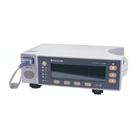
- Page 1 Operator’s Manual Nellcor OxiMax N-600x Pulse Oximeter OxiMax Technology...
- Page 2 To obtain information about a warranty, if any, contact Covidien Technical Services at 1.800.635.5267 or your local representative. Purchase of this instrument confers no express or implied license under any Covidien patent to use the instrument with any pulse oximeter that is not manufactured or licensed by...
-
Page 3: Table Of Contents
Contents Safety Information ..........1 Safety Warnings ................. - Page 4 Contents Turning the Backlight On or Off ............49 Adjusting the Screen Contrast ............50 Adjusting the Backlight Brightness ........... 50 Selecting the Pleth View ..............50 Selecting the Blip View ..............51 Selecting the Real-Time Trend View ..........52 Selecting the Trend Data Display ..........
- Page 5 OXIMAX Sensor Event Record Data Available ........85 OXIMAX Sensor Event Record Not Available ........86 OXIMAX Sensor Event Record Graphical Data ........87 Viewing and Printing OXIMAX Sensor Event History Data ....89 OXIMAX Sensor Tabular Event Data ..........91 Viewing and Printing In-Sensor Tabular Event History Data ....
- Page 6 Contents Performance Considerations ........125 Overview ..................
- Page 7 OXIMAX Technology ..............164 Functional Testers and Patient Simulators ........165 Specifications ..........167 Performance ...................
- Page 8 Contents...
-
Page 9: Safety Information
Safety Information Safety Information Safety Warnings Warnings are identified by the WARNING symbol shown above. Warnings alert you to potential serious outcomes (death, injury, or adverse events) to the patient or user. WARNING: The sensor extrapolates from the date and time provided by the N-600x when recording the sensor event record to the sensor. -
Page 10: Safety Cautions
Safety Information WARNING: Chemicals from a broken LCD display panel are toxic when ingested. Use caution when handling a pulse oximeter with a broken display panel. WARNING: Pulse oximetry readings and pulse signals can be affected by certain environmental conditions, O sensor application errors, and certain patient conditions. - Page 11 Safety Information pulse oximeter’s data interface must be certified according to IEC Standard 60950 for data-processing equipment or IEC Standard 60601-1 for electromedical equipment. All combinations of equipment must be in compliance with IEC Standard 60601-1-1 systems requirements. Anyone who connects additional equipment to the signal input port or signal output port (N-600x data port connector) configures a medical system and is therefore responsible for ensuring...
- Page 12 Safety Information Page Left Intentionally Blank N-600x Operator’s Manual...
-
Page 13: Introduction
Introduction Introduction WARNING: The N-600x is intended only as an adjunct in patient assessment. It must be used in conjunction with clinical signs and symptoms. Intended Use The Nellcor N-600x Pulse Oximetry System with N-600X Pulse Oximeter and Nellcor Sensors and Cables with O technology is indicated for prescription use only for the continuous non-invasive monitoring of functional oxygen saturation of arterial hemoglobin (SpO... -
Page 14: How To Use This Manual
How to Use this Manual All users should read this manual thoroughly. More experienced users of the N-600x can directly go to the topics for the information they require. This manual is available on the Internet at: www.covidien.com/rms N-600x Operator’s Manual... -
Page 15: Symbols, Controls, Displays And Indicators
Symbols, Controls, Displays and Indicators Symbols, Controls, Displays and Indicators About the Front Panel 12. ADJUST UP Button, page 10. 1. SpO Sensor Port, page 26. 2. Low Battery Indicator, page 15. 13. ADJUST DOWN Button, page 10. 3. AC Power Indicator, page 15. 14. -
Page 16: About The Rear Panel
Symbols, Controls, Displays and Indicators About the Rear Panel 1. Equipotential Terminal (Ground). 2. AC Power Connector, page 23. 3. Data Port Connector, page 105. 4. Fuse Holder. 5. Supply Voltage Selector Switch, page 24. Figure 2: Rear Panel Components N-600x Operator’s Manual... -
Page 17: About The Symbols
Symbols, Controls, Displays and Indicators About the Symbols The symbols, located on the rear panel of the N-600x, are as follows. Table 1: Symbols and Descriptions Symbol Description See Instructions for Use Fuse Replacement Equipotential Terminal (ground) Date of Manufacture Data Interface Applied Part - Not defibrillator proof Type BF... -
Page 18: About The Controls
Symbols, Controls, Displays and Indicators About the Controls ON/STANDBY Button Turns the monitor on and off. Note: Pressing a button, except the ON/STANDBY button, should result in either a valid or an invalid key tone (refer to Table 3). If the key pressed fails to emit a tone, contact qualified service personnel. -
Page 19: About The Displays
Symbols, Controls, Displays and Indicators • Pressing and holding the HELP/CONTRAST button while simultaneously pressing the ADJUST UP and ADJUST DOWN buttons lightens or darkens the display screen. Softkey Menu Bar Displays the current functions for each of the four softkey buttons. -
Page 20: Blip Display
Symbols, Controls, Displays and Indicators When the monitor is powered by the internal battery, the pleth display includes a horizontal battery fuel gauge positioned in the upper left corner which shows the remaining charge (operating hours) on the battery. If a monitor reporting low battery is connected to an AC power source, the battery fuel gauge displays the charging progress. -
Page 21: Real-Time Trend Display
Symbols, Controls, Displays and Indicators Real-Time Trend Display The real-time trend display includes %SpO2 and/or pulse rate trend data plots and current measured %SpO2 and pulse rates. The trend data plots are automatically updated as each new trend point is calculated, where the interval between calculations is based on the display time scale selected. - Page 22 Symbols, Controls, Displays and Indicators search indicator is lit solid and SpO and Pulse Rate will continue to be updated every second. As these conditions extend, the amount of data required continues to increase. If the dynamic averaging time reaches 40 seconds, the pulse search indicator begins flashing, the SpO and pulse rate displays flash zeros indicating a loss-of-pulse condition.
-
Page 23: About The Visual Indicators
Symbols, Controls, Displays and Indicators About the Visual Indicators Table 2: Visual Indicators Indicator Description Shows the hemoglobin oxygen saturation level. The display %SpO Display value flashes zeros during loss-of-pulse alarms and flashes the value when the SpO is outside the alarm limits. During Pulse Search, the monitor continues to update the display. - Page 24 Symbols, Controls, Displays and Indicators Table 2: Visual Indicators Indicator Description Battery Fuel Gauge Displays the battery charge remaining on the monitor. The Indicator battery fuel gauge consists of four bars, each corresponding to approximately 1.5 hours of operating time. All four bars are lit when the battery is fully charged.
-
Page 25: About The Audible Indicators
Symbols, Controls, Displays and Indicators Table 2: Visual Indicators Indicator Description Data In-Sensor Lights to indicate that the attached O sensor contains a Indicator patient sensor event record. The sensor event record information may be viewed or printed. SatSeconds Indicator Fills in clockwise as the SatSeconds alarm management system detects a %SpO reading outside of the limit setting. - Page 26 Symbols, Controls, Displays and Indicators Table 3: Audible Indicators Function Description Invalid Button Press Short, low pitched tone indicating a button has been pressed that is inappropriate for the current state of the monitor. Valid Button Press Short, medium pitched tone indicating an appropriate button has been pressed.
- Page 27 Symbols, Controls, Displays and Indicators Table 3: Audible Indicators Function Description Pulse Beep Single beep sounds for each detected pulse. The pitch of the pulse beep signal changes with a point point rise or fall in the saturation level. Volume Setting Tone Continuous tone used when adjusting the alarm volume.
- Page 28 Symbols, Controls, Displays and Indicators Page Left Intentionally Blank N-600x Operator’s Manual...
-
Page 29: Setting Up The Monitor
Setting Up the Monitor Setting Up the Monitor WARNING: To ensure patient safety, do not place the pulse oximeter in any position that might cause it to fall on the patient. WARNING: As with all medical equipment, carefully route patient cabling to reduce the possibility of patient entanglement or strangulation. - Page 30 Setting Up the Monitor WARNING: Do not lift the pulse oximeter by the pulse oximetry cable or power cord because the cable or cord could disconnect from the pulse oximeter, causing the pulse oximeter to drop on the patient. WARNING: The N-600x is not defibrillator-proof. However, it may remain attached to the patient during defibrillation or while an electrosurgical unit is in use, but the readings may be inaccurate during the defibrillation and shortly...
-
Page 31: List Of Components
Setting Up the Monitor List of Components Quantity Item -600 x Pulse Oximeter Nellcor O Sensor or Assortment Pack 10 Pulse Oximetry Cable -600 x Operator’s Manual (applicable to country of sale) and/or compact disc Power Cord (applicable to country of sale) Fuses, 0.5 A, 250 volts, slow blow, IEC (5 x 20 mm) - Page 32 Setting Up the Monitor Caution: Use only the hospital-grade power cord provided by Nellcor. 1. Set the Supply Voltage Selector switch to the applicable voltage. 2. Plug the female connector end of the power cord into the power connector on the rear of the monitor. 3.
-
Page 33: Connecting An Oximax Sensor
Setting Up the Monitor Note:If the AC power indicator is not lit, check the: • power cord • supply voltage selector switch • user-accessible fuses • AC power outlet Note: The monitor can be operated with a depleted battery when connected to an AC power outlet. A warning message displays and must be cleared by pressing the ALARM SILENCE button before the monitor can be used for patient monitoring. - Page 34 Setting Up the Monitor 1. Firmly connect a DOC-10 pulse oximetry cable to the SpO Sensor Port of the monitor. 2. Connect a Nellcor O sensor to the opposite end of the DOC-10 pulse oximetry cable. N-600x Operator’s Manual...
-
Page 35: Operating The Battery
Operating the Battery Operating the Battery WARNING: Dispose of battery in accordance with local requirements and regulations. Operating on Battery Power The N-600x monitor has an internal battery that can be used to power the monitor during transport or when AC power is not available. -
Page 36: Low Battery Indicator
Operating the Battery Service Manual. Recharge the battery when it has not been charged for three or more months. Caution: Replace the battery if fewer than four bars are lit after fully charging the battery. To charge a low or fully depleted battery, connect the monitor to AC power outlet. - Page 37 Operating the Battery available on the existing battery charge. Refer to Table 4 for a description of the low and critical battery conditions. A low battery audible alarm can be cancelled by pressing the ALARM SILENCE button. The low battery indicator and display screen message continues to display.
-
Page 38: Description Of Low And Critical Battery Conditions
Operating the Battery Description of Low and Critical Battery Conditions Table 4: Low and Critical Battery Conditions Critical State Operation Battery Battery Power normal AC/Battery charge LED LOW BATTERY LED LOW BATTERY message Audible alarm Error code none Effect of ALARM SILENCE normal Shutdown normal... - Page 39 Operating the Battery Critical State Operation Battery Battery Power normal AC/Battery charge LED LOW BATTERY LED LOW BATTERY message Audible alarm low priority Error code logged Effect of ALARM SILENCE First press silences audio alarm, second press cancels LOW BATTERY message (LED) stays on until Low Battery Condition is corrected.
- Page 40 Operating the Battery Critical State Operation Battery Battery Power Not used not displayed AC/Battery charge LED LOW BATTERY LED (flashing) LOW BATTERY message Audible alarm high priority Error code displayed and logged Effect of ALARM SILENCE none Shutdown after 10 seconds N-600x Operator’s Manual...
- Page 41 Operating the Battery Critical State Operation Battery Battery Power SpO2 - displayed. AC/Battery Charge LED - LOW BATTERY LED-on (flashing) LOW BATTERY message - The Battery Fuel Gauge Indicator shows a fully depleted battery (no bars lit). Warning message in the pleth window: UNIT WILL SHUT DOWN IF AC POWER LOST...
-
Page 42: Battery Fuel Gauge Indicator
Operating the Battery Battery Fuel Gauge Indicator The N-600x has a battery fuel gauge indicator which displays the battery power remaining on the monitor. The indicator appears on the the pleth and blip display screens. When the monitor is fully charged, all four bars are lit on the battery fuel gauge indicator. -
Page 43: Using The Monitor
Using the Monitor Using the Monitor Overview This section describes menu navigation, power on/off and display options, parameter ranges, O sensor attachments, and configuring default settings suitable for your environment. Menu Description The N-600x is outlined below. You can choose the type of trend data to view by selecting either Monitor trend or Sensor trend data in the Trend menu. -
Page 44: Menu Structure
Using the Monitor • Italicized Text — the destination of the BACK and EXIT softkeys Menu Structure Main Menu LIMITS (Limits Menu) SELECT ADULT EXIT (to Main menu) TREND (Trend Menu) MON (Monitor Menu) VIEW (Monitor Trend View Menu) DUAL SPO2 PULSE NEXT (History/Amplitude Menu) - Page 45 Using the Monitor Menu Structure SCALE (Cycle through ±5, ±10, ±15, ±20, ±25, (continued...) ±30, ±35, ±40 and ±50 (units of BPM or %SpO2, depending on the data displayed) of the max and min. values under the cursor, default to 10 to 100 for SAT trend graph and 5-250 for Pulse trend graph if there is no data point under the cursor for current view) AUTO (Based on all of the graphed trend data:...
- Page 46 Using the Monitor Menu Structure TABLE (Table Menu) (continued...) ^ (show previous table, only available when there is a previous graph; bottom/top line repeats in new table) v (show next table, only available when there is a next graph; bottom/top line repeats in new table) PRINT BACK (back to Sensor menu)
- Page 47 Using the Monitor Menu Structure DATA (On-screen options for SENSOR-R (Write-once (continued...) Sensor) sensor are: “SPO2, SPO2+BPM, DEFAULT.” On-screen options for SENSOR-RW (rewritable sensor) are: “SPO2, SPO2+BPM, DEFAULT.” SELECT toggles SENSOR-R or SENSOR-RW sensor type; up/down keys scroll through options in order.) The SENSOR-R feature supports all of the current O sensors.
-
Page 48: Parameter Ranges
Using the Monitor Menu Structure NEXT (Analog/Mode Menu) (continued...) ANALOG (Analog Voltage Select Menu) 0 VOLT 1 VOLT STEP BACK (back to Analog/Mode menu) MODE (Mode Menu) BACK (back to Analog/Mode menu) EXIT (to Main menu) BACK (back to Communication/Nurse Call menu) EXIT (to Main menu) BACK (back to Clock/Language menu) - Page 49 Using the Monitor by the clinician, and these settings remain in effect until the monitor is turned off. Table 6: Parameter Ranges Factory Factory Ranges/ Parameter Adult Neonate Selections Defaults Defaults %SpO Lower Alarm 100% Upper Alarm Limit plus 1 to Limit 100% %SpO...
- Page 50 Using the Monitor Table 6: Parameter Ranges Factory Factory Ranges/ Parameter Adult Neonate Selections Defaults Defaults Data Port ASCII, GRAPH, ASCII ASCII Mode OXINET, CLINICAL, PHILIPS, SPACELBS, MARQ (GE Marquette), DATEX (Datex- Ohmeda) Default Pleth, Blip Pleth Pleth Display Real-Time Trend Format Display Low to high...
-
Page 51: Turning On The Monitor
Using the Monitor Table 6: Parameter Ranges Factory Factory Ranges/ Parameter Adult Neonate Selections Defaults Defaults Real-Time 48, 36, 24, 12, 30 minutes 30 minutes Trend Scale 8, 4, 2, 1 hours, 30 minutes Response Normal or Fast Normal Normal Mode Normally High, Normally Low... - Page 52 Using the Monitor each time the N-600x is turned on as described in the following procedure. Caution: If any indicator or display element does not light when the pulse oximeter is turned on, do not use the pulse oximeter. Instead, contact qualified service personnel, your local Nellcor representative, or Nellcor’s Technical Services Department.
- Page 53 Using the Monitor 3. Once the display test portion of POST completes, the software version displays for approximately five seconds and a sequence of three ascending tones sound. Note:The software version shown above is only a sample. Check your monitor for the current software version installed. The software version is often needed when calling Nellcor’s Technical Services Department or your local Nellcor representative for technical assistance.
-
Page 54: Oximax Sensor Attached
Using the Monitor WARNING: If you do not hear the POST pass tone, do not use the pulse oximeter. WARNING: Ensure the speaker is clear of any obstructions. Failure to do so could result in an inaudible alarm tone. Note:In addition to serving as the POST pass verification, the POST pass tone also functions as an audible confirmation that the speaker is performing properly. - Page 55 Using the Monitor For a sensor containing data, the message identifies the sensor data type. For a blank sensor, the message identifies the monitor’s current data type setting used to write data to the sensor. The data type settings are SpO and SPO +BPM.
- Page 56 Using the Monitor Notice the movement of the blip bar or plethysmographic waveform or beating heart indicating the monitor is displaying real-time data. Listen for the pulse beep tone. If the pulse beep tone does not sound with each pulse, it is an indication the pulse beep volume is set to zero, the speaker is malfunctioning, or the signal is corrupt.
-
Page 57: No Oximax Sensor Attached
Using the Monitor No O Sensor Attached Upon successful completion of the POST process, the monitor sounds a one-second tone indicating that the monitor has passed the POST. The monitor displays dashes [ - - - ] and the Pulse Search indicator is not lit, indicating the monitor failed to detect an O sensor. -
Page 58: Adjusting The Screen Contrast
Using the Monitor • pressing the ALARM SILENCE button • any alarm Adjusting the Screen Contrast 1. With the monitor in the normal monitoring mode, press and hold the HELP/CONTRAST button while pressing the ADJUST UP or ADJUST DOWN button until the desired contrast is obtained. -
Page 59: Selecting The Blip View
Using the Monitor 2. Press the VIEW softkey. 3. Press the PLETH softkey. The pleth view displays. Selecting the Blip View The blip view displays the SpO , pulse rate, blip bar, and limits in a larger format for easier viewing. 1. -
Page 60: Selecting The Real-Time Trend View
Using the Monitor Selecting the Real-Time Trend View The real-time trend view displays the %SpO and/or pulse rate trend data. The real-time trend submenu enables you to: • select the trend data display, • set the trend time scale display, and •... -
Page 61: Setting The Trend Time Scale Display
Using the Monitor 3. Press the TREND softkey. 4. Press the VIEW softkey. 5. Press any of the trend softkeys (DUAL, SPO2, or PULSE). Setting the Trend Time Scale Display 1. Press the SETUP softkey. 2. Press the VIEW softkey. 3. -
Page 62: Setting The Pulse Beep Volume
Using the Monitor 4. Press the ZOOM softkey. 5. Press the SCALE softkey to cycle the trend amplitude scale display through ±5 points, ±10 points, ±15 points, ±20 points, ±25 points, ±30 points, ±35 points, ±40 points and ±50 points above and below the newest - rightmost - trend data point. -
Page 63: Setting The Date And Time
Using the Monitor 1. With the monitor in the normal monitoring mode, press the ALARM SILENCE button until the alarm volume level displays and sounds on the monitor. 2. While continuing to press the ALARM SILENCE button, press and hold the ADJUST UP or ADJUST DOWN button to increase or decrease the volume. -
Page 64: Setting The Alarm Silence Duration
Using the Monitor 2. Press the NEXT softkey. 3. Press the CLOCK softkey. 4. Press the SET softkey. 5. Press the SELECT softkey to select the TIME and DATE fields as shown in the graphic below. TIME HOURS : MINUTES : SECONDS (16 : 46 : 05) DATE DAY - MONTH - YEAR (02 - JAN - 06) 6. -
Page 65: Disabling Audible Alarms
Note: The ability to set the alarm silence duration to OFF can be enabled or disabled by qualified service personnel as described in the N-600x Service Manual. The N-600x Service Manual is available on the Internet at: www.covidien.com/rms N-600x Operator’s Manual... -
Page 66: Selecting The Standby Mode
Using the Monitor WARNING: Do not disable the audible alarm function or decrease the audible alarm volume if the patient’s safety could be compromised. 1. With the monitor in the normal monitoring mode, press the ALARM SILENCE button until the alarm silence duration setting displays. -
Page 67: Adult-Pediatric Or Neonatal Settings
Using the Monitor 1. Verify the N-600x is monitoring a patient and the alarm limits are configured to the patient being monitored. 2. Disconnect the sensor from the monitor. 3. Press the ALARM SILENCE button to silence the audible alarms. 4. -
Page 68: Setting Patient Adult-Pediatric Or Neonatal Modes
Using the Monitor WARNING: Each time the pulse oximeter is used, check alarm limits to ensure that they are appropriate for the patient being monitored. Setting Patient Adult-Pediatric or Neonatal Modes 1. With the monitor in the normal monitoring mode, press the LIMITS softkey. -
Page 69: Alarm Limit Changed Indicator
Using the Monitor Alarm Limit Changed Indicator Alarm limits that have been changed from the institution or factory default settings are identified by a decimal point (.) after the displayed reading (%SpO or BPM). The changed parameter is also identified by a decimal point on the alarm limits screen. Setting Alarm Limits The Alarm Limit display enables you to adjust the upper and lower saturation and pulse rate limits. - Page 70 Using the Monitor 1. Press the LIMITS softkey. The current alarm limits display. NEONATE LIMITS %SP02 %SPO2 UPPER LOWER SAT-S EXIT ADULT SELECT 2. Press the ADULT or NEO softkey to select the Adult-Pediatric or Neonatal alarm limits screen. 3. Press the SELECT softkey to select the parameter to be adjusted.
-
Page 71: Setting Satseconds Alarm Limit
Using the Monitor institutional default limits are effected. Factory or institutional defaults are selected by qualified service personnel by following the procedures outlined in the N-600x Service Manual. Setting SatSeconds Alarm Limit Refer to Using SatSeconds on page 153, for more information on the SatSeconds feature. -
Page 72: Setting Monitor Response Mode
Using the Monitor Setting Monitor Response Mode The purpose of the response mode is to set the response time of the N-600x algorithm calculation of the SpO (the response mode does not affect the N-600x algorithm’s calculation of pulse rate). The trending interval (2- or 4-seconds) is updated automatically by the monitor to roughly correspond with the SpO calculation... -
Page 73: Selecting The Display Language
Using the Monitor 4. Use the ADJUST UP or ADJUST DOWN buttons to select the desired response mode. 5. Press the EXIT softkey. Selecting the Display Language The N-600x can be programmed to display the information in various languages. The languages available are: ENGLISH DANSK (Danish) DEUTSCH (German) -
Page 74: Oximax Sensor Messages
Using the Monitor 4. Use the ADJUST UP or ADJUST DOWN buttons to select the desired language. 5. Press the EXIT softkey. Note: The selected language displays until the monitor is turned OFF. The selected language can be set as a default by qualified service personnel by following the procedures outlined in the N-600x Service Manual. -
Page 75: Oximax Sensor Adjust Condition Messages
Using the Monitor display all of the messages. When multiple screens are required, navigation between screens can be accomplished by using the NEXT, BACK, and EXIT softkeys. sensor messages may be disabled. Refer to OXIMAX Sensor Messages on page 66 for selecting the O Sensor Messages, Enable/Disable function. - Page 76 Using the Monitor • Message — EAR/FOREHEAD SENSOR? • Message — NASAL/EAR SENSOR? • Message — O ADHESIVE SENSOR • Message — SECURE CABLE • Message — HEADBAND • Message — WARM SITE • Message — BANDAGE ASSEMBLY • Message — NAIL POLISH •...
-
Page 77: Using Monitor Trend Data
Using Monitor Trend Data Using Monitor Trend Data Overview The trend displays enable you to view trend data. Two types of trend data can be viewed: • Monitor trend data stored in the monitor • Patient event data stored in the O sensor (single-patient-use O sensors only) and can be... - Page 78 Using Monitor Trend Data The monitor stores up to 48 hours of 4-second trend data or 24 hours of 2-second trend data. The amount of trend data displayed on the screen is determined by using the ZOOM softkey. The settings available are 20 and 40 seconds, 15 or 30 minutes, and 1, 2, 4, 8, 12, 24, 36, or 48 hours.
-
Page 79: Storing Trend Data
Using Monitor Trend Data Storing Trend Data Whenever the N-600x is turned on, it stores the monitor %SpO and pulse rate readings in memory every 2- or 4-seconds (regardless of whether the N-600x is monitoring a patient or not). The N-600x can store up to 48 hours of 4-second trend data or 24 hours of 2-second trend data. -
Page 80: Selecting The Trend Data Display Scale
Using Monitor Trend Data message(s) function. This display is the first message displayed when an O sensor is connected to the monitor. Selecting the Trend Data Display Scale The trend scale is the amount of trend data displayed on the screen. - Page 81 Using Monitor Trend Data 5. Press the ZOOM softkey. The Zoom menu displays. Pressing the TIME softkey cycles the displayed trend time scale through 48 hours, 36 hours, 12 hours, 8 hours, 4 hours, 2 hours, 1 hour, 30 minutes, 15 minutes, 40 seconds and 20 seconds. Note: The 20-second and 40-second trend displays are in tabular format.
-
Page 82: Reading The Trend Data Display
Using Monitor Trend Data Pressing the BACK softkey returns the monitor to the Monitor menu. Reading the Trend Data Display The following table identifies the components of the trend data display. Table 7: Reading Trend Display Item Description Amount of trend data displayed on the screen. Settings available are 20 and 40 seconds, 15 and 30 minutes, 1, 2, 4, 8, 12, 24, 36, and 48 hours. -
Page 83: Dual Trend Data Display
Using Monitor Trend Data Dual Trend Data Display The dual trend data display shows both oxygen saturation (%SpO ) levels and pulse rate (bpm) trend data. 1. With the monitor in the normal monitoring mode, press the TREND softkey. 2. Press the MONITR softkey. 3. -
Page 84: Pulse Rate Trend Display
Using Monitor Trend Data 4. Press the SPO softkey. SpO trend data displays. Pulse Rate Trend Display 1. With the monitor in the normal monitoring mode, press the TREND softkey. 2. Press the MONITR softkey. 3. Press the VIEW softkey. 4. -
Page 85: Pulse Amplitude Trend Data Display
Using Monitor Trend Data on the display. Refer to OXIMAX Sensor Type on page 71, to set up the desired trend data scale. Pulse amplitude cannot be displayed on the histogram display. 1. With the monitor in the normal monitoring mode, press the TREND softkey. -
Page 86: Clearing Trend Information
Using Monitor Trend Data 3. Press the VIEW softkey. 4. Press the NEXT softkey. 5. Press the AMP softkey. The pulse amplitude units (PAU) trend data displays. The PAU reading (12 : 20) indicates the pulse amplitude units (upper and lower) at the cursor position (dashed line). The cursor moves right or left using the ADJUST UP (right) and ADJUST DOWN (left) buttons. - Page 87 Using Monitor Trend Data Note: Press NO and then EXIT to close this function without deleting the trend data. 5. Press the YES softkey. All the trend data clears and the monitor sounds three beeps. N-600x Operator’s Manual...
- Page 88 Using Monitor Trend Data Page Left Intentionally Blank N-600x Operator’s Manual...
-
Page 89: Using Oximax Sensor Event Records
Using OXIMAX Sensor Event Records Using O Sensor Event Records Overview WARNING: The sensor extrapolates from the date and time provided by the N-600x when recording the sensor event record to the sensor. The accuracy of the date/time is determinated by the date/time of the N-600x. It is recommended that the N-600x user set the time/date to the correct value before a sensor event record-enabled sensor is connected, and that this date/time not be changed while... -
Page 90: Setting Up Oximax Sensor Messages
Using OXIMAX Sensor Event Records maximum number of events that can be stored in an O sensor is typically 100. Event records can only be viewed after an O sensor containing patient alarm data (event records) has been connected to an O monitor with SENSOR enabled. -
Page 91: Setting In-Sensor Data Type
Using OXIMAX Sensor Event Records 1. With the monitor in the normal monitoring mode, press the SETUP softkey. 2. Press the SENSOR softkey. 3. Press the MSG softkey. 4. Press the ADJUST UP or ADJUST DOWN button to toggle the ENABLE message. - Page 92 Using OXIMAX Sensor Event Records 2. Press the SENSOR softkey. 3. Press the DATA softkey. Note: O sensor data type settings are displayed on the monitor as shown in the figure below (in-sensor data type). If no sensor is connected, both sensor types and the full set of options for each are displayed.
-
Page 93: Oximax Sensor Data Type
Using OXIMAX Sensor Event Records 6. Press the EXIT softkey to set the O sensor type. Sensor Data Type When an O sensor with no previously recorded patient data is connected to the O monitor, a “DATA TYPE: . . .” message is displayed briefly at the bottom of the display after the sensor type message. -
Page 94: Oximax Sensor Event Record Not Available
Using OXIMAX Sensor Event Records A corresponding “DATA IN SENSOR” message is also displayed at the bottom of the display. After 4 to 6 seconds, if all the data has been read from the O sensor, the message is replaced with the main menu. -
Page 95: Oximax Sensor Event Record Graphical Data
Using OXIMAX Sensor Event Records sensor memory chip in the prior monitoring situation, a TREND/ SENSOR option is unavailable. A sample event display without data is shown below. The message clears when the graph or summary closes. Sensor Event Record Graphical Data Graphical representations of patient event history is only available on single-patient-use O sensors. - Page 96 Using OXIMAX Sensor Event Records • sensor is disconnected • sensor is removed from the patient The graph title shows the data type (EVENT GRAPH) in the upper left corner. The number of the displayed event and the total number of events recorded in the O sensor are shown to the right of the title (example, 2/2).
-
Page 97: Viewing And Printing Oximax Sensor Event History Data
Using OXIMAX Sensor Event Records The PRINT softkey enables you to print the displayed event graph. The BACK softkey returns to the previous TREND/SENSOR submenu level. Viewing and Printing O Sensor Event History Data With the monitor in the normal monitoring mode, you can connect a printer, capable of printing graphs, to the monitor data port connector in order to print O sensor event history data. - Page 98 Using OXIMAX Sensor Event Records 5. Press the PRINT softkey to print the displayed screen. 6. Press the EXIT softkey. A sequence of %SpO + BPM (saturation plus pulse rate) “dual-view” event graphs are shown below. The dual-view graph is the same as a single graphical event history graphs, except the graphs are compressed horizontally to allow both %SpO pulse rate graphs to be shown for the same event.
-
Page 99: Oximax Sensor Tabular Event Data
Using OXIMAX Sensor Event Records Sensor Tabular Event Data The O sensor tabular event data is a listing of all events recorded on the O sensor’s memory chip. SUMMARY DATE START %SPO2 06JAN 63/70 13:55 00:03:00 75/80 06JAN 60/64 11:07 00:10:30 76/83 06JAN... -
Page 100: Viewing And Printing In-Sensor Tabular Event History Data
Using OXIMAX Sensor Event Records The ADJUST UP and ADJUST DOWN buttons on the monitor panel are used to move through the Event Summary table line by line. The PRINT softkey enables you to print the displayed event graph. The BACK softkey returns to the previous TREND/SENSOR submenu level. -
Page 101: Printing Monitor Trend Data
Printing Monitor Trend Data Printing Monitor Trend Data Overview Trend information (monitor and in-sensor event history) can be sent to a personal computer or to a serial printer. Note: The protocol settings must be set to ASCII MODE for printing text data or GRAPH MODE for printing graphical data. Printing 1. - Page 102 Printing Monitor Trend Data 4. Press the COMM softkey. 5. Set the BAUD rate to the appropriate number using the ADJUST UP button. 6. Press the SELECT softkey to select PROTOCOL. 7. Set the PROTOCOL to ASCII for text printing or GRAPH for graph printing using the ADJUST UP button.
-
Page 103: Monitor Trend Data In Ascii Mode
Printing Monitor Trend Data 12. Press the PRINT softkey. ASCII printout: GRAPH printout: Monitor Trend Data in ASCII Mode Refer to Printing Monitor Trend Data on page 93 for the procedure to print trend information. The format of data displayed when a trend printout is shown in Figure 3. -
Page 104: Trend Data In Graph Mode
Printing Monitor Trend Data not present, a corruption of the data may have been detected and the data should be ignored. Figure 3: ASCII Mode Printout Note: Once trend printing has begun, printing can only be aborted by turning off the N-600x or the printer. Trend Data in Graph Mode Refer to Printing Monitor Trend Data on page 93 for the procedure to print trend information. - Page 105 Printing Monitor Trend Data When a real-time printout or display is being transmitted to a printer or PC, a new line of data is displayed every 2 seconds. Column headings are displayed or printed after every 25 lines, or if one of the values in the column heading changes. Readings are displayed at 4-second intervals if the SpO response mode is set to normal and at 2-second intervals when the SpO2 response...
- Page 106 Printing Monitor Trend Data An example of real-time data output is shown in Figure 5. Figure 5: Real-Time Printout N-600x Operator’s Manual...
-
Page 107: Column Headings
Printing Monitor Trend Data Column Headings Every 25 line of the data output consists of a column heading. A column heading is displayed whenever the value within a column heading changes. There are three column-heading lines shown in the printout. Using the top row as the starting point there are 25 lines before the second row of column headings is printed. -
Page 108: Alarm Limits
Printing Monitor Trend Data Note: The numbers may change if the monitor is serviced and receives a software upgrade. Alarm Limits The last data field in the top line indicates the upper and the lower alarm limits for %SpO and for the pulse rate (PR). In the example above the lower alarm limit for SpO is 85% and the upper alarm limit is 100%. -
Page 109: Data Column Headings
Printing Monitor Trend Data Data Column Headings Actual column headings are in the second row of the column heading line. Patient data presented in the chart, from left to right, is the: • time the patient data was recorded • current %SpO value •... -
Page 110: Operating Status
Printing Monitor Trend Data Patient information is highlighted in the display above. Parameter values are displayed directly beneath the heading for each parameter. In this example, the %SpO is 100 and the pulse rate is 190 beats per minute. The “*” next to the 190 indicates that 190 beats per minute is outside of the alarm limits, indicated in the top row, for pulse rate. - Page 111 Printing Monitor Trend Data Code Definition Patient Motion Pulse Rate Upper Limit Alarm Pulse Rate Lower Limit Alarm Pulse Search Saturation Upper Limit Alarm Saturation Lower Limit Alarm Sensor Disconnect Sensor Off Note: An O sensor disconnect causes three dashes [- - -] to be displayed in the patient data section of the display or printout.
- Page 112 Printing Monitor Trend Data Page Left Intentionally Blank N-600x Operator’s Manual...
-
Page 113: Using The Data Port
Using the Data Port Using the Data Port Overview Patient data can be output through the data port on the back of the N-600x by connecting it to a PC or serial printer. When connecting the N-600x to a printer or PC, verify proper operation prior to clinical use. -
Page 114: Data Port Pinouts
Using the Data Port certified to UL-1950 or IEC-60950. The cable used must have a braided shield that provides 100% coverage, such as a Belden cable (Belden part number 9609) or equivalent. The shield must have a 360-degree connection to the metal shell on the N-600x's DB-15 connector and to the connector on the PC or serial printer. - Page 115 Using the Data Port Table 8: Data Port Pinouts Signal Name AN_PLETH (analog pleth waveform output) NC_COM (relay closure nurse call, common lead) TxD represents the Transmit Data line, and RxD is the Receive Data line. The pin layouts (as viewed from the rear panel of the N-600x) are illustrated in Figure 6.
-
Page 116: Data Port Setup
Using the Data Port Data Port Setup Use the Data Port Setup display to set the baud rate and the protocol of the data port on the N-600x. The Data Port Setup display is accessed by pressing the COMM softkey on the Setup menu. 1. -
Page 117: Using The Nurse Call Interface
Using the Data Port • GRAPH • OXINET • PHILIPS • SPACELBS (Spacelabs) • MARQ (GE Marquette) • DATEX (Datex-Ohmeda) 6. Press the EXIT softkey. Using the Nurse Call Interface WARNING: The nurse call feature should not be used as the primary source of alarm notification. -
Page 118: Setting Nurse Call Rs-232 Polarity
Using the Data Port on battery. The relay-based nurse call function is available when the monitor is operating either on AC power or on battery power. The remote location is signaled anytime there is an audible alarm. If the audible alarm has been turned off or silenced, the nurse call function is also turned off. -
Page 119: Setting Nurse Call Relays Normally Open/Closed
Using the Data Port 2. Press the NEXT softkey twice and then press the NCALL softkey. 3. Press the NORM + softkey OR press the NORM - softkey. 4. Press the EXIT softkey. Setting Nurse Call Relays Normally Open/Closed Data port pins 7 and 15 provide a relay that closes when an alarm is sounding on the monitor. - Page 120 Using the Data Port pin's parameter varies over its full range of values, as indicated in Table 9. Table 9: Analog Pinouts Parameter Parameter Range %SpO2 100% Pulse Rate 250 bpm Pleth Waveform For example, as the current value of %SpO varies from 0 to 100%, the voltage from pin 6 to ground (pin 10) varies from 0 to 1 volt.
- Page 121 Using the Data Port Selecting the STEP softkey causes the voltage to increase from 0 to 1 volt at 1/10 -volt increments, with each step lasting at least 1 second. Nellcor recommends that a qualified service personnel perform the calibration of the attached device as described in the N-600x Service Manual.
- Page 122 Using the Data Port Page Left Intentionally Blank N-600x Operator’s Manual...
-
Page 123: Oximax Sensors And Accessories
OXIMAX Sensors and Accessories Sensors and Accessories WARNING: The sensor extrapolates from the date and time provided by the N-600x when recording the sensor event record to the sensor. The accuracy of the date/time is determined by the date/time of the N-600x. It is recommended that the N-600x user set the time/date to the correct value before a sensor event record-enabled sensor is connected, and that this date/time not be changed while... -
Page 124: Selecting An Oximax Sensor
OXIMAX Sensors and Accessories Selecting an O Sensor WARNING: Before use, carefully read the O sensor directions for use, including all warnings, cautions, and instructions. WARNING: Do not use a damaged O sensor or pulse oximetry cable. Do not use an O sensor with exposed optical components. - Page 125 A Sensor Accuracy Grid listing all of the O sensors used with the N-600x is available on the Internet at: www.covidien.com/rms When selecting an O sensor, consider the patient’s weight and activity level, the adequacy of perfusion, and the available sensor sites, the need for sterility, and the anticipated duration of monitoring.
- Page 126 OXIMAX Sensors and Accessories Performance Considerations on page 127, for more information on O sensor performance. Table 10: Nellcor O Sensor Models and Patient Sizes Patient Sensor Model Size >10 kg FAST adhesive FAST reflectance oxygen sensor oxygen sensor (Sterile, <3 or >40 kg single...
-
Page 127: Oximax Sensor Features
OXIMAX Sensors and Accessories Table 10: Nellcor O Sensor Models and Patient Sizes Patient Sensor Model Size Softcare nonadhesive sensor, SC-PR <1.5 kg single-patient-use, preterm infant Softcare nonadhesive sensor, SC-NEO 1.5 to 5 kg single-patient-use, neonate Softcare nonadhesive sensor, SC-A >40 kg single-patient-use, adult The pulse oximetry cable DOC-10 connects the N-600x pulse... -
Page 128: Biocompatibility Testing
See Figure 8 on page 122. • GCX Roll Stand. See Figure 9 on page 123. • Soft-Sided Carrying Case. See Figure 10 on page 124. Accessories for the N-600x are also listed on the Internet at: www.covidien.com/rms N-600x Operator’s Manual... -
Page 129: Gcx Mounting Plate
OXIMAX Sensors and Accessories GCX Mounting Plate An optional mounting plate is available for the N-600x. This mounting plate fits standard, commercially available GCX mount brackets, and is used to securely mount the N-600x to a wall bracket or a roll stand. The mounting plate attaches to the bottom of the N-600x as shown in Figure 7. -
Page 130: Gcx Vertical Wall Mount Arm
OXIMAX Sensors and Accessories GCX Vertical Wall Mount Arm An optional vertical wall mount arm and 19-inch channel are available and can be ordered separately for the N-600x. The vertical wall mount arm attaches to the N-600x GCX mounting plate as in Figure 8. For further instructions regarding connecting the vertical wall mount arm, refer to the illustrated directions for use included with the vertical wall mount arm. -
Page 131: Soft-Sided Carrying Case
OXIMAX Sensors and Accessories connecting the GCX roll stand, refer to the illustrated directions for use included with the GCX roll stand. Figure 9: GCX Roll Stand Soft-Sided Carrying Case An optional soft-sided carrying case is available from Nellcor for the N-600x. - Page 132 OXIMAX Sensors and Accessories contains two pockets for O sensors, cables, and Operator’s Manual. You can order the carrying case directly from Nellcor. Figure 10: Soft-Sided Carrying Case N-600x Operator’s Manual...
-
Page 133: Performance Considerations
Performance Considerations Performance Considerations WARNING: Pulse oximetry readings and pulse signals can be affected by certain ambient environmental conditions, sensor application errors, and certain patient conditions. See the appropriate sections of the manual for specific safety information: • Safety Information on page 1 •... -
Page 134: Dysfunctional Hemoglobins
Performance Considerations • dysfunctional hemoglobins • poor peripheral perfusion • excessive patient movement • venous pulsations • intravascular dyes, such as indocyanine green or methylene blue • externally applied coloring agents (nail polish, dye, pigmented cream) • defibrillation Dysfunctional Hemoglobins Dysfunctional hemoglobins such as carboxyhemoglobin, methemoglobin, and sulphemoglobin are unable to carry oxygen. -
Page 135: Pulse Rates
Performance Considerations Pulse Rates The N-600x only displays pulse rates between 20 and 250 bpm. Detected pulse rates above 250 bpm are displayed as 250. Detected pulse rates below 20 are displayed as 0. Sensor Performance Considerations WARNING: Pulse oximetry readings and pulse signal can be affected by certain ambient conditions, O sensor application errors, and certain patient conditions. - Page 136 Performance Considerations • failure to cover the O sensor site with opaque material in high ambient light conditions Loss-of-pulse signal can occur for the following reasons: • the O sensor is applied too tightly • a blood pressure cuff is inflated on the same extremity as the one with the O sensor attached •...
- Page 137 Performance Considerations • use an adhesive O sensor that improves patient skin contact • use a new O sensor with fresh adhesive backing • keep the patient still, if possible If poor perfusion affects performance, consider using the MAX-R sensor; it obtains measurements from the nasal septal anterior ethmoid artery, an artery supplied by the internal carotid.
- Page 138 Performance Considerations Page Left Intentionally Blank N-600x Operator’s Manual...
-
Page 139: Troubleshooting
Troubleshooting Troubleshooting Overview This section describes how to troubleshoot common problems while using your N-600x pulse oximeter. This chapter includes information about the on-screen help function, error code messages, and how to obtain technical help and support. WARNING: If you are uncertain about the accuracy of any measurement, check the patient's vital signs by alternate means;... -
Page 140: Accessing Multiple Topics
Troubleshooting Accessing Multiple Topics You can access multiple on-screen help topics and select a specific topic to view. Follow the example described below to access the SatSeconds help topic. 1. From the Main menu, press the HELP/CONTRAST button. The HELP MAIN window appears. 2. - Page 141 Troubleshooting The SatSeconds help topic contains a total of six consec- utive help windows. 4. Press the NEXT softkey to scroll through each window of the selected help topic. 5. Press NEXT. 6. Press NEXT. N-600x Operator’s Manual...
-
Page 142: Accessing Single Topics
Troubleshooting 7. Press NEXT. 8. Press NEXT. 9. Press BACK to view the previous windows. Continue to press BACK to return to the HELP MAIN window. 10. Press EXIT to return to the monitor’s Main menu. Accessing Single Topics The on-screen help enables you to access single topics by pressing the HELP/CONTRAST button from a monitor submenu. - Page 143 Troubleshooting 2. Press the HELP/CONTRAST button. The HELP LIMITS window appears. 3. Press ADJUST UP or ADJUST DOWN to highlight an available help topic (SELECT, NEO and ADULT). For this example, hightlight SELECT. 4. Press SHOW. The HELP LIMITS SELECT window appears. 5.
-
Page 144: Error Codes
Troubleshooting 7. Press BACK. 8. Press ADJUST DOWN to highlight ADULT and the press SHOW. The HELP LIMITS ADULT window appears. 9. Press EXIT to return to the LIMITS display. Error Codes When the N-600x detects an error condition, it may display “EEE” followed by an error code. - Page 145 Troubleshooting the screen and display the message “EEE XXX,” and sound a low priority alarm. Cycling the power clears these errors. Table 12: Error Codes Error Error Action Code Message DEFAULTS The current power on default LOST settings have been lost and returned to factory defaults.
- Page 146 Troubleshooting Table 12: Error Codes Error Error Action Code Message TRENDS LOST Monitor trends are corrupted and will be cleared. Turn off the monitor, and then back on again. 701-716, POWER SUPPLY The monitor power supply has 720-724, FAILURE detected an error. The monitor will 732-740, shutdown after 10 seconds.
-
Page 147: Prompts And Error Messages
Troubleshooting Prompts and Error Messages Prompt/Error Messages are displayed in the menu area. Prompt messages alert you for a response while error messages provide information.The two figures below show examples of a prompt and an error message. Table 13 describes the N-600x prompt/error messages. Time-out is the maximum time that the message remains displayed. - Page 148 Troubleshooting Advisory messages are centered on the display. Prompts are those messages requiring a response (yes or no) and will be left justified. Table 13: Prompt/Error Messages Exit Exit on Time-out Message Alarm Displayed Resolution (seconds) Alarm Silence CLOCK None After the If the N 600x...
- Page 149 Troubleshooting Table 13: Prompt/Error Messages Exit Exit on Time-out Message Alarm Displayed Resolution (seconds) Alarm Silence DEFAULTS LOST None After the If the N 600x monitor is detects that power cycled. power settings have been lost. DELETE When After TRENDS? attempting to responding to delete trend data...
-
Page 150: Primary Speaker Failure
Troubleshooting Table 13: Prompt/Error Messages Exit Exit on Time-out Message Alarm Displayed Resolution (seconds) Alarm Silence SENSOR TYPE First message Time displayed when a sensor is connected to the monitor. Primary Speaker Failure The N-600x may detect a failure of the primary speaker and sound a high-pitched, slow-pulsing piezo tone. -
Page 151: Help And Support
Nellcor representative. The N-600x Service Manual, which is for use by qualified service personnel, provides additional troubleshooting information. The N-600x Service Manual is available on the Internet at: www.covidien.com/rms N-600x Operator’s Manual... - Page 152 Troubleshooting The following is a list of possible errors and suggestions. Table 14: Common Problems and Resolutions Problem Resolution • Ensure the supply voltage selector switch There is no response when I press the ON/STANDBY button. is set to the proper voltage. •...
- Page 153 Troubleshooting Table 14: Common Problems and Resolutions Problem Resolution The Pulse Search Indicator is lit • Check the O sensor directions for for more than 10 seconds use to determine if an appropriate (before any measurements are sensor is being used and if it is taken).
- Page 154 Troubleshooting Table 14: Common Problems and Resolutions Problem Resolution The Pulse Search Indicator • Check the status of your patient. illuminates after successful measurements have been • Perfusion may be too low for the made. monitor to track the pulse. Test the instrument on another patient.
-
Page 155: Emi (Electromagnetic Interference)
Troubleshooting Table 14: Common Problems and Resolutions Problem Resolution Error Code: “EEE XXX” • Press the ON/STANDBY button and allow followed by a number the monitor to shut off completely. Then appears. press the button again to turn the monitor back on. If the error code persists, record the number and provide this information to a qualified service personnel, or your... - Page 156 Troubleshooting Directive 93/42/EEC. These limits are designed to provide reasonable protection against harmful interference in a typical medical installation. However, because of the proliferation of radio-frequency transmitting equipment and other sources of electrical noise in health care environments (for example, electrosurgical units, cellular phones, mobile two-way radios, electrical appliances, and high-definition television), it is possible that high levels of such interference due to close proximity or strength of a source may...
-
Page 157: Obtaining Technical Assistance
Return the N-600x by any shipping method that provides proof of delivery. The N-600x Operator’s and Service Manuals are available on the Internet at: www.covidien.com/rms N-600x Operator’s Manual... - Page 158 Troubleshooting Page Left Intentionally Blank N-600x Operator’s Manual...
-
Page 159: Maintenance
Maintenance Maintenance Overview This section describes the steps required to maintain, service, and properly clean your N-600x pulse oximeter. Follow local governing ordinance and recycling instructions regarding the disposal or recycling of the N-600x and accessories. Service WARNING: The cover should be removed only by qualified service personnel. -
Page 160: Cleaning
Maintenance Cleaning Caution: Do not spray, pour, or spill any liquid on the N-600x, its accessories, connectors, switches, or openings in the chassis. For surface-cleaning and disinfecting the monitor, follow your institution's procedures or: • The N-600x may be surface-cleaned by using a soft cloth dampened with either a commercial, nonabrasive cleaner or a solution of 70% alcohol in water, and lightly wiping the surfaces of the monitor. -
Page 161: Using Satseconds
Using SatSeconds Using SatSeconds Overview With traditional alarm management, upper and lower alarm limits are set for monitoring oxygen saturation. During monitoring, as soon as an alarm limit is violated by as little as one percentage point, an audible alarm immediately sounds. When the %SpO level fluctuates near an alarm limit, the alarm sounds each time the limit is violated. - Page 162 Using SatSeconds The alarm response time, assuming a SatSeconds limit set at 50 and a lower alarm limit set at 90, is described and illustrated below. In this example, the %SpO level drops to 88 (2 points) and remains there for a period of 2 seconds (2 points x 2 seconds = 4 SatSeconds).
-
Page 163: Satseconds "Safety Net
Using SatSeconds Saturation levels may fluctuate rather than remain steady for a period of several seconds. Often, the %SpO levels may fluctuate above and below the alarm limit, reentering the non-alarm range several times. During such fluctuations, the N-600x pulse oximeter integrates the number of %SpO points, both positive and negative, until either the SatSeconds limit (SatSeconds time setting) is reached,... - Page 164 Using SatSeconds When the indicator is filled, indicating that the SatSeconds setting has been reached, an audible alarm sounds and the displayed %SpO rate flashes. As with traditional alarm management, the audible alarm may be silenced by pressing the ALARM SILENCE button. N-600x Operator’s Manual...
-
Page 165: Factory Default Settings
Factory Default Settings Factory Default Settings Overview The N-600x is shipped with factory default settings. Authorized technical personnel using the procedures described in the N-600x Service Manual can change default settings. Neonate Default Settings Table 15: Neonate Factory Defaults Parameter Setting Monitoring Mode %SpO... -
Page 166: Adult Default Settings
Factory Default Settings Table 15: Neonate Factory Defaults Parameter Setting Language English Nurse Call Polarity Normally Low Pulse Beep Volume 4 of 10 Pulse Rate Lower Alarm Limit 90 bpm Pulse Rate Upper Alarm Limit 190 bpm Real-Time Trend Display %SpO Real-Time Trend Scale 30 Minutes... - Page 167 Factory Default Settings Table 16: Adult Factory Defaults Parameter Setting Alarm Volume 7 of 10 Backlight Brightness 8 (Battery Power) 10 (AC Power) Data Port Baud Rate 9600 Data Port Protocol ASCII Display Contrast Midrange Display Format Pleth Language English Nurse Call Polarity Normally Low Pulse Beep Volume...
- Page 168 Factory Default Settings Page Left Intentionally Blank N-600x Operator’s Manual...
-
Page 169: Principles Of Operation
Principles of Operation Principles of Operation Overview The N-600x uses pulse oximetry to measure functional oxygen saturation in the blood. Pulse oximetry works by applying an sensor to a pulsating arteriolar vascular bed, such as a finger or toe. The O sensor contains a dual light source and a photo detector. -
Page 170: Automatic Calibration
Principles of Operation Because oxyhemoglobin and deoxyhemoglobin differ in light absorption, the amount of red and infrared light absorbed by blood is related to hemoglobin oxygen saturation. The monitor uses the pulsatile nature of arterial flow to identify the oxygen saturation of arterial hemoglobin. During systole, a new pulse of arterial blood enters the vascular bed, and blood volume and light absorption increase. -
Page 171: Functional Versus Fractional Saturation
Principles of Operation Functional versus Fractional Saturation This pulse oximeter measures functional saturation – oxygenated hemoglobin expressed as a percentage of the hemoglobin that can transport oxygen. It does not detect significant amounts of dysfunctional hemoglobin, such as carboxyhemoglobin or methemoglobin. -
Page 172: Oximax Technology
Principles of Operation temperature, the partial pressure of carbon dioxide (PCO 2,3-DPG, and fetal hemoglobin. See Figure 12. Figure 12: Oxyhemoglobin Dissociation Curve Technology The N-600x pulse oximeter is designed to use Nellcor O brand sensors, which integrate the O technology. -
Page 173: Functional Testers And Patient Simulators
Principles of Operation then loads the data to begin monitoring. As the pulse oximeter reads the information, it displays the O sensor model number. This process only takes a couple of seconds. The O sensor model number disappears after 5 seconds. Pulse oximeters containing O technology, including the N-600x, use calibration data contained in the O... - Page 174 Principles of Operation Many functional testers and patient simulators have been designed to interface with the pulse oximeter's expected calibration curves and may be suitable for use with Nellcor monitors and/or sensors. Not all such devices, however, are adapted for use with the Nellcor O digital calibration system.
-
Page 175: Specifications
Specifications Specifications Performance Measurement Range 1% to 100% Pulse Rate 20 to 250 beats per minute (bpm) Perfusion Range 0.03% to 20% Accuracy Saturation 70 to 100% ±2 digits 2, 3 Adult 2, 3, 4 60 to 80% ±3 digits Adult and Neonate Low Sat 4, 5 70 to 100% ±2 digits... - Page 176 Specifications Accuracy Saturation accuracy varies by sensor type. Refer to the Sensor Accuracy Grid at www.covidien.com/rms. Accuracy specifications were validated using measurements of healthy non-smoking adult volunteers during controlled hypoxia studies spanning the specified saturation ranges. Subjects were recruited from the local population and comprised both men and women ranging in age from 18-50 years old, and spanned a range of skin pigmentations.
-
Page 177: Electrical
Specifications Display Update Interval 1 second Electrical Instrument Power Rated at 100 to 120 volts AC (nominal 120 VAC) Requirements or 220 to 240 volts AC (nominal 230 VAC), 20 volt/amps to be compliant with IEC 60601 clause 10.2.2. Fuses Quantity 2, 0.5 A, 250 volts, slow blow, IEC (5 x 20 mm). -
Page 178: Environmental Conditions
Specifications Battery Shelf Life • 4 months, new fully-charged battery (when monitor is placed in "Shelf-mode" by qualified service personnel using the procedures indicated in the N-600x Service Manual • After 4 months storage in "Shelf- mode", the N-600x will run for 33% of stated battery life Complies With... - Page 179 Specifications Operation Altitude 390 m to 3,012 m 1,254 ft. to 9,882 ft.) Atmospheric Pressure 70 kPa to 106 kPa (20.6 in. Hg to 31.3 in. Hg) Relative Humidity 15% to 95% non condensing to be compliant with IEC 60601 1, sub clause 44.5...
-
Page 180: Physical Characteristics
Specifications Sensor Power Dissipation Sensor Dissipation 52.5 mW 52.5 mW 52.5 mW 52.5 mW 52.5 mW 52.5 mW 52.5 mW Oxiband OXI 52.5 mW Oxiband OXI 52.5 mW Durasensor DS 100A OxiCliq P 52.5 mW OxiCliq N 52.5 mW OxiCliq I 52.5 mW OxiCliq A 52.5 mW... -
Page 181: Compliance
Specifications Compliance Item Compliant With Equipment classification Safety Standards: IEC 60601 (same as EN60601 1), CSA 601.1, UL 60601-1, EN865, EN/IEC 60601 2 (second edition) Type of protection Class I (on AC power) Internally powered (on battery power) Degree of protection Type BF Applied part Mode of operation... -
Page 182: Manufacturer's Declaration
Specifications Item Compliant With Radiated and conducted EN 55011, Group 1, Class B emissions Operation with electrical line FDA Reviewer’s Guide voltage variations Magnetic field susceptibility RS 101 in MIL-STD-461E Manufacturer’s Declaration WARNING: The use of accessories, sensors, and cables other than those specified may result in increased emission and/ or decreased immunity of the N 600x pulse oximeter. - Page 183 Specifications Table 18: Electromagnetic Immunity The N 600x is suitable for use in the specified electromagnetic environment. The customer and/or user of the N 600x should assure that it is used in an electromagnetic environment as described below. Electromagnetic Immunity Compliance 60601-1-2 Environment...
- Page 184 Specifications Table 18: Electromagnetic Immunity The N 600x is suitable for use in the specified electromagnetic environment. The customer and/or user of the N 600x should assure that it is used in an electromagnetic environment as described below. Electromagnetic Immunity Compliance 60601-1-2 Environment...
- Page 185 Specifications Table 18: Electromagnetic Immunity The N 600x is suitable for use in the specified electromagnetic environment. The customer and/or user of the N 600x should assure that it is used in an electromagnetic environment as described below. Electromagnetic Immunity Compliance 60601-1-2 Environment...
- Page 186 Specifications Table 19: Electromagnetic Immunity, RF Portable Equipment For portable and mobile communication equipment. The N 600x is suitable for use in the specified electromagnetic environment. The customer and/or user of the N 600x should assure that it is used in an electromagnetic environment as described below: Electromagnetic Immunity...
- Page 187 Specifications Table 19: Electromagnetic Immunity, RF Portable Equipment For portable and mobile communication equipment. The N 600x is suitable for use in the specified electromagnetic environment. The customer and/or user of the N 600x should assure that it is used in an electromagnetic environment as described below: Electromagnetic Immunity...
- Page 188 Specifications Table 19: Electromagnetic Immunity, RF Portable Equipment For portable and mobile communication equipment. The N 600x is suitable for use in the specified electromagnetic environment. The customer and/or user of the N 600x should assure that it is used in an electromagnetic environment as described below: Electromagnetic Immunity...
- Page 189 Specifications Table 20: Recommended Separation Distances Recommended Separation Distances between Portable and Mobile RF Communications Equipment and the N 600x (IEC 60601 Frequency of 150 KHz to 80 MHz to 800 MHz to Transmitter 80 MHz 800 MHz 2.5 GHz Equation d = 1.2P d = 1.2P...
- Page 190 Specifications Table 21: Cables Cables and Maximum Complies With Length Sensors • RF emissions, 10.0 ft. (3 m) pulse CISPR 11, oximetry Class B/Group 1 cable Software 10.0 ft. (3 m) • Harmonic download emissions, cable, RS IEC 61000-3-2 serial, 15 to 9 pin “D”...
- Page 191 Specifications Table 21: Cables Cables and Maximum Complies With Length Sensors • RF emissions, sensors: CISPR 11, Class B/Group 1 1.5 ft. (0.5 m) 3.0 ft. (0.9 m) • Harmonic emissions, 1.5 ft. (0.5 m) IEC 61000-3-2 1.5 ft. (0.5 m) •...
- Page 192 Specifications Table 21: Cables Cables and Maximum Complies With Length Sensors • RF emissions, 3.0 ft. (0.9 m) Durasensor CISPR 11, sensor Class B/Group 1 100A • Harmonic emissions, IEC 61000-3-2 • Voltage fluctuations/flicker emission, IEC 61000-3-3 • Electrostatic discharge (ESD), IEC 61000-4-2 •...
- Page 193 Specifications Table 21: Cables Cables and Maximum Complies With Length Sensors • RF emissions, 3 cable OxiCliq CISPR 11, sensors: 3.0 ft. (0.9 m) Class B/Group 1 • Harmonic emissions, IEC 61000-3-2 • Voltage fluctuations/flicker 4.0 ft. (1.2 m) emission, Dura sensors: IEC 61000-3-3...
- Page 194 Specifications Page Left Intentionally Blank N-600x Operator’s Manual...
-
Page 195: Clinical Study
Clinical Study Clinical Study Overview This section contains data from the clinical study conducted for the Nellcor™ sensors used with the Nellcor™ N-600X Pulse Oximeter. One (1) prospective, controlled hypoxia clinical study was conducted to demonstrate the accuracy of Nellcor™ sensors when used in conjunction with the Nellcor™... -
Page 196: Study Population
Clinical Study Study Population Table 22: Demographic Data Type Class Total Male Gender Female Caucasian Hispanic Race African American Asian 19-48 Weight 108-250 Very light Olive Skin pigment Dark olive/Medium black Extremely dark/Blue black N-600x Operator’s Manual... -
Page 197: Study Results
Clinical Study Study Results Accuracy was calculated using the root mean square difference (RMSD). Table 23: SpO Accuracy for Nellcor™ Sensors vs. CO-oximeters MAX-A MAX-N MAX-FAST Data Data Data Decade Arms Arms Arms Points Points Points 60-70 3.05 2.89 2.22 70-80 2.35 2.32... - Page 198 Clinical Study Figure 13: Modified Bland-Altman Plot Test Sensor; Avg CO-oximeter value Avg CO-oximeter value 70-100% SpO 70-100% SpO Oximetry board with MAX-A sensor Trendline of MAX-A sensor Oximetry board with MAX-N sensor Trendline of MAX-N sensor Oximetry board with MAX-FAST sensor Trendline of MAX-FAST sensor N-600x Operator’s Manual...
-
Page 199: Adverse Events Or Deviations
Clinical Study Adverse Events or Deviations The study was conducted as expected with no adverse events and no deviations from the protocol. Conclusion The pooled results indicate that for a saturation range of 60-80% for SpO , the acceptance criterion was met for the monitoring system when tested with MAX-A, MAX-N and MAX-FAST sensors. - Page 200 Clinical Study Page Left Intentionally Blank N-600x Operator’s Manual...
-
Page 201: Index
Index Index Calculated Saturation 163 Calibration 151 AC Power Indicator 15 Carrying Case Adult Soft-Sided 123 Backlight Brightness 159 Default Settings 158 Cautions 2 Adult-Pediatric Patients 59 Cleaning 152 Alarm Limit Display 61 Clock 56 Alarm Off 102 Clock Settings Lost 137 Alarm Silence 102 Confirmation Tone 17 Alarm Silence Duration Display 56... - Page 202 Index Default Settings Graph Mode Printout 96 Adult 158 Graphical Sensor Event Record Data 87 Factory 157 Neonate 157 Help Defaults Lost 137 accessing single topics 134 Delete Trends? 141 multiple topics 132 Deutsch 65 Histogram Trend Data Display 76 Disabling Audio Alarms 57 Hospital Type Environments 5 Disinfecting 152...
- Page 203 Index menu Performance Considerations softkey 11 Pulse Oximeter 125 Sensor 127 MO 103 Performance Verification 125 Monitor Accuracy Tolerance 167 PH 103 Performance Considerations 125 PL 103 Returning 149 Pleth Display 11 Monitor Displays Dashes 49 Plethysmographic Waveform Display 15 Monitor Trend Data 69 Portuguese 65 Power-On Self-Test (POST) 44...
- Page 204 Index Roll Stand 122 Settings Lost 137 SH 103 SL 103 Safety Checks 151 SO 103 Safety Warnings 1 softkey SatSeconds menu bar 11 Alarm Management 153 Describing 153 Soft-Sided Carrying Case 123 Display 155 Software Version 45 Safety Net 155 Spanish 65 Saturation Specifications 167...
- Page 205 Index Invalid Button Press 18 Histogram 76 Low Priority Alarm 18 Pulse Amplitude 77 Medium Priority Alarm 18 Pulse Rate 76 Piezo Tone 18 Reading the 74 Power-On Self-Test Pass 18 Scale 72 Pulse Beep 19 SpO2 75 Valid Button Press 18 Trend Scale 72 Volume Setting Tone 19 Troubleshooting...
- Page 206 Index N-600x Operator’s Manual...
- Page 208 Part No. 10055994 Rev B 2014-02 COVIDIEN, COVIDIEN with logo and Covidien logo are U.S. and internationally registered trademarks of Covidien AG. ™* Trademark of its respective owner. Other brands are trademarks of a Covidien company. ©2011 Covidien. Covidien llc, 15 Hampshire Street, Mansfield, MA 02048 USA.
Need help?
Do you have a question about the Nellcor OxiMax N-600x and is the answer not in the manual?
Questions and answers