Table of Contents
Advertisement
Advertisement
Table of Contents

Related Manuals for Covidien Nellcor Series


Summary of Contents for Covidien Nellcor Series
- Page 1 Operator’s Manual Nellcor Bedside SpO Patient Monitoring System...
- Page 2 © 2018 Covidien. All rights reserved. COVIDIEN, COVIDIEN with logo, and Covidien logo and Positive Results for Life are U.S. and internationally registered trademarks of Covidien AG. ™* brands are trade- marks of their respective owners. Other brands are trademarks of a Covidien company.
-
Page 3: Table Of Contents
Table of Contents Introduction Overview ..........1-1 Safety Information . - Page 4 4.5.1 Set Patient Mode (Type) ......... .4-5 4.5.2 Set SpO and Pulse Rate Alarm Limits...
- Page 5 Preventive Maintenance Overview ..........7-1 Cleaning .
- Page 6 11.4 Environmental Conditions ....... 11-2 11.5 Tone Definition ......... . 11-3 11.6 Performance Specifications .
- Page 7 List of Tables Table 1-1. Safety Symbol Definitions................1-1 Table 2-1. Display Colors......................2-7 Table 2-2. Symbol Descriptors ...................2-8 Table 3-1. Standard Items....................3-2 Table 4-1. Alarm Conditions .................... 4-10 Table 4-2. Audio Status...................... 4-12 Table 4-3. Menu Structure and Factory Defaults............4-20 Table 4-4. Service Menu Settings (Password Protected)........4-21 Table 5-1. Nurse Call Relay Pins States for NORMALLY + .........5-5 Table 5-2. Nurse Call Relay Pins States for NORMALLY –...
- Page 8 Page Left Intentionally Blank...
- Page 9 List of Figures Figure 2-1. Front and Side Panel Components ............2-3 Figure 2-2. Display Components .................2-4 Figure 2-3. Rear Panel Components................2-7 Figure 3-1. Connecting a Pulse Oximetry Sensor to Interface Cable....3-6 Figure 4-1. Sample Initial Screen .................4-3 Figure 4-2. Save Change Screen ..................4-5 Figure 4-3. QUICK ACCESS Menu ..............4-7 Figure 4-4. ...
- Page 10 Figure 10-5. Third SpO Event: Triggers SatSeconds™ Alarm......10-7 Figure A-1. Modified Bland-Altman for SpO2 (All Data - No Motion): vs. (SpO2 - SaO ) ................A-5 Figure A-2. Modified Bland-Altman for Pulse Rate (All Data - No Motion): ECG HR vs. (Pulse Rate - ECG HR)............A-6 Figure A-3. ...
- Page 11 Figure A-21. Correlation Plot for SpO2 (All Data - Low Saturation): vs. SpO2 ................... A-26 Figure A-22. Correlation Plot for Pulse Rate (All Data - Low Saturation): ECG HR vs. Pulse Rate ................A-27 Figure A-23. Modified Bland-Altman for SpO2 (All Data - Motion): vs.
- Page 12 Page Left Intentionally Blank...
-
Page 13: Introduction
1 Introduction Overview This manual contains information for operating the Nellcor™ bedside SpO patient monitoring system. This manual applies to the following product: PM100N Note: Before use, carefully read this manual, accessory Instructions for Use, and all precautionary information and specifications. Safety Information This section contains important safety information related to general use of the Nell- cor™... -
Page 14: Warnings
Introduction Warnings 1.2.2 WARNING: Explosion hazard — Do not use the monitoring system in the presence of flammable anesthetics. WARNING: Explosion hazard — Do not use the monitoring system with other manufacturer's batteries. Do not use different types or models of batteries such as dry batteries, nickel-metal hydride batteries, or Lithium-ion batteries together. - Page 15 Safety Information WARNING: Always disconnect and remove the monitoring system and sensors during magnetic resonance imaging (MRI) scanning. Attempting to use the monitoring system during an MRI procedure could cause burns or adversely affect the MRI image or the monitoring system's accuracy.
-
Page 16: Cautions
Introduction WARNING: Do not silence or decrease the volume of the audible alarm if patient safety could be compromised. WARNING: Do not preset different alarm limits for the same or similar equipment within a single area. Cautions 1.2.3 ... - Page 17 Caution: For best product performance and measurement accuracy, use only accessories supplied or recommended by Covidien. Use accessories according to the manufacturer's directions for use and institutional standards. Use only accessories that have passed the recommended biocompatibility testing in compliance with ISO 10993-1.
-
Page 18: Technical Assistance
Introduction Technical Assistance Technical Services 1.3.1 For technical information and assistance, contact Covidien or a local Covidien repre- sentative. Covidien Technical Services: Patient Monitoring 15 Hampshire Street Mansfield, MA 02048 USA 1.800.635.5267, 1.925.463.4635, or contact a local Covidien representative www.covidien.com When calling Covidien or a local Covidien representative, have the monitoring system serial number available. -
Page 19: Warranty Information
Warranty Information The information contained in this document is subject to change without notice. Covidien makes no warranty of any kind with regard to this material, including, but not limited to, the implied warranties or merchantability and fitness for a particular purpose. - Page 20 Introduction Page Left Intentionally Blank Operator’s Manual...
-
Page 21: Product Overview
2 Product Overview Overview WARNING: Patient conditions may result in erroneous readings. If the measurements are suspect, verify the reading using another clinically accepted measurement method. This chapter contains basic information about the Nellcor™ bedside SpO patient monitoring system. The monitoring system relies on unique oximetry technology and design to provide hospitals, clinicians, and caregivers accurate, timely data, which includes a number of parameters. -
Page 22: Indications For Use
Product Overview Indications for Use WARNING: The monitoring system is intended only as an adjunct in patient assessment. It must be used in conjunction with clinical signs and symptoms. The Nellcor™ Bedside SpO Patient Monitoring System is intended for prescription use only for the continuous non-invasive monitoring of functional oxygen satura- tion of arterial hemoglobin (SpO ) and pulse rate. -
Page 23: Product Views
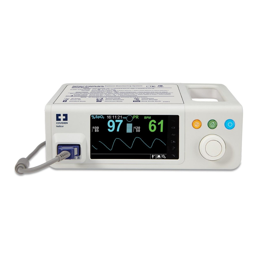
Product Views Product Views Front Panel and Display Components 2.4.1 Front and Side Panels Figure 2-1. Front and Side Panel Components Quick Guide Provides a summary of instructions for operation of the monitoring system. Silence Alarm button Press to toggle between disabling and re-enabling the audible alarm. -
Page 24: Figure 2-2. Display Components
Product Overview LCD display panel Use to view all graphic and numeric patient information as well as status conditions and warning messages. connector Use to connect to the interface cable and SpO sensor. Display Figure 2-2. Display Components Upper and lower alarm limits Reflects upper and lower SpO and pulse rate alarm limits. - Page 25 Product Views Alarm silenced icon The yellow icon indicates Alarm Silenced. This indicator also shows the time remaining in the alarm silence period. The red icon indicates Audio OFF. Audio OFF icon Pulse rate real-time value Displays the pulse rate in beats per minute. Current upper and lower alarm limit settings appear as smaller values to the left of the dynamic pulse rate value.
- Page 26 Product Overview Sensor message indicator Appears when the sensor is invalid. Options menu icon Select to customize options and features. Alarm limits menu icon Select to customize audible alarm limits. Patient mode area Reflects the current patient mode selected. Adult mode — Indicates alarm limits are set to adult limit •...
-
Page 27: Rear Panel
Product Views Table 2-1. Display Colors Color Condition Function Cyan numeric Value and plethysmographic waveform Green numeric Steady Pulse rate value Black background General background Red background High priority alarm condition Flashing SpO Yellow background Alarm condition Green font Informative message Steady Yellow font Low or medium priority message Red font... -
Page 28: Product And Carton Label Symbols
Product Overview Product and Carton Label Symbols 2.4.3 Table 2-2. Symbol Descriptors Symbol Description Symbol Description Type BF Data port Class II equipment Date of manufacture Prescription only device Keep dry Attention, consult accompanying doc- Fragile uments Atmospheric pressure limitations UL listed Humidity limitations CE Mark Temperature limitations... -
Page 29: Installation
3 Installation Overview This chapter contains information for the installation and set up of the Nellcor™ bedside SpO patient monitoring system prior to first-time usage. Safety Reminders WARNING: Ensure the speaker is clear of any obstruction. Failure to do so could result in an inaudible alarm tone. -
Page 30: Unpacking And Inspection
Compact disc (CD) and/or Operator's Manual Lithium-ion battery pack, M-BPL-1 (21) 5 hour AC power cord Covidien provides soft copy of monitoring system manuals on a compact disc for easy access and print-on-demand. Order a printed Nellcor™ bedside SpO patient monitoring system Operator’ s Manual at no cost or a printed Nellcor™... -
Page 31: Power
Power Power WARNING: In the USA, do not connect to an electrical outlet controlled by a wall switch, since this increases the risk of AC power loss to the monitoring system. Caution: The monitoring system must be connected to an appropriate power source. ... -
Page 32: Internal Battery Power
Note: Remove the battery if the monitoring system is not likely to be used for six (6) months. Note: Covidien strongly recommends fully recharging the battery whenever the time between recharges exceeds six (6) months. Note: The monitoring system may not operate if the battery charge is critically low. -
Page 33: Nellcor™ Pulse Oximetry Sensor Connection
WARNING: Do not use any other cables to extend the length of the Covidien-approved interface cable. Increasing the length will degrade signal quality and may lead to inaccurate measurements. Operator’s Manual... -
Page 34: Figure 3-1. Connecting A Pulse Oximetry Sensor To Interface Cable
Installation WARNING: Use only the Covidien-approved pulse oximetry sensor and interface cables. Use of other cables can have an adverse effect on performance. Do not attach any cable intended for computer use to the sensor port. WARNING: Failure to cover the applied pulse oximetry sensor with opaque material while operating under high ambient light conditions may result in inaccurate measurements. - Page 35 Nellcor™ Pulse Oximetry Sensor Connection A Sensor Message occurs when the device cannot obtain an SpO level or a pulse rate. Note: If the sensor is not connected firmly, the monitoring system could lose signal from patient. Note: Reference Performance Considerations, p.
- Page 36 Installation Page Left Intentionally Blank Operator’s Manual...
-
Page 37: Operation
60601-1-2: 2007 and IEC 60601-1-2:2014. These limits are designed to provide reasonable protection against harmful interference in a typical medical installation. WARNING: For best product performance and measurement accuracy, use only accessories supplied or recommended by Covidien. Use accessories according to their respective Directions for Use. -
Page 38: Apply Power To Monitoring System
Operation WARNING: Do not use damaged pulse oximetry sensors. Do not use with exposed optical components. Do not immerse completely in water, solvents, or cleaning solutions, since pulse oximetry sensors and connectors are not waterproof. Do not sterilize by irradiation, steam or ethylene oxide. -
Page 39: Turn Off The Monitoring System
Apply Power to Monitoring System Figure 4-1. Sample Initial Screen Ensure the POST pass tone sounds when POST completes. When the monitoring system completes power-on self-test (POST), a POST pass tone sounds. This functions as an audible confirmation of proper speaker performance. If the speaker does not func- tion, the monitoring system emits a continuous audible tone to alert the user that the speaker is not functioning and that the alarm warning sounds will be inaudible. -
Page 40: Menu Navigation
Operation Observe the message System is shutting down on the screen. Note: Press the Power On/Off button for at least 15 seconds to turn off the monitoring system after any situation involving continuous resets or a system lock. Menu Navigation Navigating menu options on the monitoring system requires manual manipulation of the three buttons and the knob. -
Page 41: Choose Patient Settings
Choose Patient Settings Figure 4-2. Save Change Screen The LCD panel displays easy-to-read numeric values for patient oxygen saturation and pulse rate in cyan and green, respectively. Reference Table 2-1. on page 2-7. Choose Patient Settings Set Patient Mode (Type) 4.5.1 Select the desired patient mode: Adult, Pediatric or Neonatal. To set patient mode: Select the Patient Mode icon. - Page 42 Operation WARNING: Prior to each use of the monitoring system, check the alarm limits to ensure they are appropriate for the patient being monitored. Ensure alarm limits do not exceed the standard thresholds set by the institution. WARNING: Do not preset different alarm limits for the same or similar equipment within a single area.
-
Page 43: Figure 4-3. Spo 2 Quick Access Menu
Choose Patient Settings reaches full, a medium priority alarm sounds. by adjusting the setting. The higher the SatSeconds™ value, the less frequent the alarm. Available SpO alarm limit thresholds • Upper and lower SpO alarm limit thresholds – alarm inhibition to disable audible alarms for SpO limit violations –... -
Page 44: Figure 4-4. Quick Access Pr Menu
Operation Figure 4-4. QUICK ACCESS PR Menu To set alarm limits using the QUICK ACCESS menus: Navigate to the SpO or pulse rate (PR) area of the main screen. A white outline appears around the area. Select the desired area, then make the desired settings. ALARM/LIMITS Menu ... -
Page 45: Set Spo 2 Waveform
Choose Patient Settings Set SpO WAVEFORM 4.5.3 Caregivers may choose to set sweep speed of the plethysmographic waveform and opt to view the tabular or graphical trend screen. To access the WAVEFORM Menu: Navigate to the waveform display area and select it to display the WAVEFORM Menu. Figure 4-6. Waveform Display Area Highlighted Figure 4-7. SpO Waveform Menu... -
Page 46: Manage Alarms And Alarm Limits
Operation Manage Alarms and Alarm Limits WARNING: Setting alarm limits to off or extreme high or low values will reduce alarm efficacy. WARNING: Do not silence the audible alarm or decrease its volume if patient safety could be compromised. -
Page 47: Audible Alarm Indicators
Note: If the monitoring system fails to perform as specified, contact Covidien Technical Services, a qualified service technician, or a local supplier for assistance. Audible Alarm Indicators 4.6.1 ... -
Page 48: Visual Alarm Indicators
Operation Table 4-2. Audio Status Alarm Icon Status Alarm Silenced Audio OFF To silence an audible alarm: Press the Silence Alarm button to immediately silence the alarm tone. The alarm resumes after the Alarm Silence period, if the alarm condition remains. Take the appropriate corrective action. ... -
Page 49: Set Additional Patient Modes
Set Additional Patient Modes Set Additional Patient Modes Additional patient modes are available to set the monitoring system to Normal or Fast Response Mode, Homecare Mode, Sleep Study Mode, or Standard Mode. Mode (Response Mode) 4.7.1 The response mode (Normal or Fast) establishes the rate at which the monitoring system responds to changes in the SpO data.The calculation of pulse rate and the recording of trend data are not affected. -
Page 50: Homecare Mode
Operation Homecare Mode 4.7.2 Set the monitoring system to Homecare Mode when a lay person will be using the monitoring system outside of a hospital or other professional care setting. Home- care Mode provides limited functionality to simplify operation. Note: A four-digit password is required to switch to Homecare Mode. -
Page 51: Sleep Study Mode
Set Additional Patient Modes Figure 4-11. Delete or Save Trend Data The “Switched to Homecare Mode” message appears. Until a sensor is connected to the patient and the monitoring system, the following screens appear: Figure 4-12. Sensor Messages Figure 4-13. Homecare Mode Main Screen with Homecare Icon Sleep Study Mode 4.7.3 Set the monitoring system to Sleep Study Mode when a sleep study will be per-... -
Page 52: Figure 4-14. Switch To Sleep Study Mode
Operation Note: A four-digit password is required to switch to Sleep Study Mode. To set the monitoring system to Sleep Study Mode: Access the OPTIONS Menu. Select Change Patient Mode, then select Switch to Sleep Study Mode. Figure 4-14. Switch to Sleep Study Mode Confirm the entry into Sleep Study Mode, or select Cancel. -
Page 53: Standard Mode
Set Additional Patient Modes Note: It is recommended to delete all trend data when configuring the monitoring system for a different patient. The “Switched to Sleep Study Mode” message appears. Figure 4-17. Sleep Study Mode Main Screen When the buttons and knob have not been used for 30 seconds, the screen dims. Standard Mode 4.7.4 Standard Mode is the factory default operating mode. -
Page 54: Select Optional Settings
Operation Note: It is recommended to delete all trend data when configuring the monitoring system for a different patient. The “Switched to Standard Mode” message appears. Select Optional Settings Volume 4.8.1 Use this option to adjust volume controls. To set the desired audible tone volume: Access the OPTIONS Menu. -
Page 55: Brightness
Select Optional Settings Brightness 4.8.2 Use this option to adjust the screen brightness. To set the desired brightness: Access the OPTIONS Menu. Select Brightness. Figure 4-20. Brightness Menu Item Select and set the desired brightness. Figure 4-21. Brightness Selection Operator’s Manual 4-19... -
Page 56: Menu Structure And Factory Defaults
Operation Menu Structure and Factory Defaults The monitoring system ships with factory default settings. To set different institu- tional default settings, contact a qualified service technician. Note: The ability to change alarm limits is inhibited in Homecare Mode. Table 4-3. Menu Structure and Factory Defaults Factory Default Item Available Selections... -
Page 57: Table 4-4. Service Menu Settings (Password Protected)
Menu Structure and Factory Defaults Table 4-3. Menu Structure and Factory Defaults (Continued) Factory Default Item Available Selections Adult Pediatric Neonatal Delete All Trend Data No, Yes Service Menu (For qualified service technicians only) PATIENT MODE Menu Adult option Sets Alarm Limits to standard default thresholds for adult patients Pediatric option Sets Alarm Limits to standard default thresholds... -
Page 58: Maintenance Reminder
Schedule regular maintenance and safety checks with a qualified service technician every 24 months. Reference Periodic Safety Checks, p. 7-4. In the case of mechanical or functional damage, contact Covidien or a local Covidien representative. Refer- ence Technical Assistance, p. 1-6. -
Page 59: Data Management
5 Data Management Overview This chapter contains information for accessing patient trend data obtained using the Nellcor™ bedside SpO patient monitoring system. Trend data can be viewed anytime patient trend is stored in the monitoring system. The monitoring system stores up to 96 hours of trend data. When the monitoring system begins measuring vital signs, it saves data every four (4) seconds during normal conditions, and every one (1) second during alarm conditions. -
Page 60: Graphical Trend Data
Data Management To scroll through Tabular Trend Data: Turn the knob to scroll through the trend data. Clockwise rotation moves forward to newer data. • Counterclockwise rotation moves backward to older data. • Press the knob again to adjust the scroll granularity. Larger values scroll through more data faster. -
Page 61: External Data Communication
External Data Communication Press the knob to activate scrolling. Turn the knob to scroll through the trend data. Clockwise rotation moves forward to newer data. • Counterclockwise rotation moves backward to older data. • After reviewing trend data, press the Home button to exit the graphical trend view. External Data Communication ... -
Page 62: Figure 5-3. Nurse Call Interface Pin Layout
Data Management The nurse call feature of the monitoring system works in conjunction with the nurse call system of the institution when the monitoring system sounds an audible alarm. It is operational regardless of whether the monitoring system uses AC power or battery power, as long as a proper connection between the nurse call port and the host system exists. -
Page 63: Trend Data Download
External Data Communication Table 5-1. Nurse Call Relay Pins States for NORMALLY + Monitoring system ON Monitoring system OFF NORMALLY + No alarm Audible alarm or alarm silenced Pin 1 and Pin 2 Open Closed Closed Pin 2 and Pin 3 Closed Open Open When the nurse call polarity is set to NORMALLY –, the nurse call relay operation is... - Page 64 Data Management ASCII format compatible with several spreadsheet programs (ASCII 2) • Note: Users may choose to import patient trend data to a spreadsheet program. To do so, users must export trend data using the ASCII 2 format option. Have a qualified service technician set this option prior to attempting a data download.
-
Page 65: Figure 5-4. Trend Data Download Option
External Data Communication Figure 5-4. Trend Data Download Option Connect a mini-USB cable from the monitoring system to the computer. Grasp the mini-USB end of the cable. Firmly insert into the bottom mini-USB data port. Firmly insert the USB end of the cable into a USB port on the host system. Ensure the computer properly identifies the monitoring system. - Page 66 Data Management Wait for the Output Complete message to indicate the download is complete. Save patient trend data to the personal computer disk or to an alternate source, depending on institutional requirements. To launch HyperTerminal Click the Start menu in the main task bar. Mouse over the Programs submenu, then Accessories, then Communications, then the HyperTerminal option.
-
Page 67: Figure 5-6. Sample Trend Data Printout
External Data Communication Ensure the parity bit is set to none. Ensure the stop bit is set to 1. Ensure the flow control is set to none. Click the OK button. Note: To test for trend data download connectivity, proceed with the download by pressing the Start option. -
Page 68: Table 5-3. Status Codes 5
Codes, p. 5-10. COM port USB Driver Alternatives Load the appropriate driver from the product CD or thumb drive into the connected • computer. The USB driver will automatically load. Contact Technical Services or a local Covidien representative. • 5-10 Operator’s Manual... -
Page 69: Figure 5-7. Sample Bridge Driver Installer Window
Insert the Nellcor™ bedside SpO patient monitoring system compact disc (CD) into the designated personal computer (PC). Copy the COVIDIEN USB to UART Bridge Driver zip file to the PC, installing it in the desired program folder. Right-click on the zipped folder. -
Page 70: Figure 5-8. Sample New Hardware Wizard Screen
Data Management Allow the PC to sense the new hardware and load the InstallShield Wizard, which guides users through the entire setup process. Do not click the Cancel button. Figure 5-8. Sample New Hardware Wizard Screen At the prompt from the InstallShield Wizard, click on the Next button to copy the driver to the PC. -
Page 71: Figure 5-9. Sample Device Manager Button Under Hardware Tab
External Data Communication Reboot the PC for changes to take effect. From the Start menu, click the Settings menu option and select the Control Panel option. Select the System option to open the System Properties window. Click the Hardware tab, then the Device Manager button. Figure 5-9. Sample Device Manager Button Under Hardware Tab Select the Ports option from the resulting list. -
Page 72: Figure 5-10. Sample Hardware List In Device Manager Window
Data Management Figure 5-10. Sample Hardware List in Device Manager Window Double click the Silicon Labs CP210x USB to UART Bridge option. Note: The listed COM port should match the HyperTerminal COM port designation. Reference To launch HyperTerminal, p. 5-8. 5-14 Operator’s Manual... -
Page 73: Figure 5-11. Sample Initial Usb To Uart Bridge Properties Window
External Data Communication Figure 5-11. Sample Initial USB to UART Bridge Properties Window Click the Port Settings tab. Set the bits per second to one of the following baud rates: 19200 or 115200. The factory default is 19200 bps. Note: The monitoring system’s baud rate setting must match the baud rate setting for the USB to UART Bridge. -
Page 74: Firmware Upgrades
Data Management Figure 5-12. Sample Baud rate list under Port Settings tab Click the OK button to complete the process. Reference To download trend data, p. 5-6, and proceed to step 8, utilizing HyperTerminal to connect to the monitoring system. Firmware Upgrades 5.4.3 Contact a qualified service technician to perform any firmware upgrade to the mon- itoring system, as described in the Service Manual. -
Page 75: Overview
6 Performance Considerations Overview This chapter contains information about optimizing the performance of the Nell- cor™ bedside SpO patient monitoring system. Verify the performance of the monitoring system by following the procedures out- lined in the Service Manual. Have a qualified service technician perform these proce- dures prior to initial installation in a clinical setting. -
Page 76: Overview
Performance Considerations Performance Considerations Overview 6.3.1 This section contains information for optimizing the performance of the monitoring system. Verify the performance of the monitoring system by following the procedures out- lined in the SRC-MAX Pulse Oximetry Functional Tester Technical Manual. Have a qual- ified service technician perform these procedures prior to initial installation in a clinical setting and every 24 months as part of preventive maintenance. -
Page 77: Sensor Performance Considerations
Use. WARNING: Use only Covidien-approved pulse oximetry sensors and pulse oximetry cables when connecting to the sensor connector. Connecting any other cable or sensor influences the accuracy of sensor data, since this may lead to adverse results. ... - Page 78 Performance Considerations Signal Loss Loss-of-pulse signal can occur for several reasons. Pulse oximetry sensor applied too tightly • Inflation of a blood pressure cuff on the same extremity as the attached pulse oximetry • sensor Arterial occlusion proximal to the pulse oximetry sensor •...
-
Page 79: Reducing Emi (Electromagnetic Interference)
Performance Considerations Reducing EMI (Electromagnetic Interference) 6.3.4 WARNING: Keep patients under close surveillance when monitoring. It is possible, although unlikely, that radiated electromagnetic signals from sources external to the patient and the monitoring system can cause inaccurate measurement readings. ... -
Page 80: Obtaining Technical Assistance
Performance Considerations Increase the separation between the interfering equipment and the monitoring system. • Connect the equipment into an outlet on a circuit different from that to which the other • device(s) are connected. The monitoring system generates, uses, and can radiate radio frequency energy and, if not installed and used in accordance with these instructions, may cause harmful interference with other susceptible devices in the vicinity. -
Page 81: Preventive Maintenance
7 Preventive Maintenance Overview This chapter describes the steps required to maintain, service, and properly clean the Nellcor™ bedside SpO patient monitoring system. Cleaning WARNING: Do not spray, pour, or spill any liquid on the monitoring system, its accessories, connectors, switches, or openings in the chassis. -
Page 82: Recycling And Disposal
Explosion hazard — Do not connect the battery reversed in positive (+) and negative (-) terminals. Do not charge the battery with polarities reversed. Caution: Covidien strongly recommends recharging the battery when it has not been recharged for six (6) or more months. Caution: Follow local government ordinances and recycling instructions regarding disposal or recycling of device components, including batteries. - Page 83 Battery Maintenance Caution: Do not use any chargers not specified by Covidien. Caution: Do not mistreat the battery, or use the battery in applications not recommended by Covidien. Caution: Keep the battery out of reach of children to avoid any accidents.
-
Page 84: Periodic Safety Checks
24 months. Inspect the equipment for mechanical and functional damage or deterioration. • Inspect the safety relevant labels for legibility. Contact Covidien or a local Covidien rep- • resentative, if labels are damaged or illegible. Ensure all user interface keys, cables, and accessories function normally. -
Page 85: Troubleshooting
8 Troubleshooting Overview This chapter describes how to troubleshoot common problems while using the Nellcor™ bedside SpO patient monitoring system. General WARNING: Check the patient's vital signs by alternate means should there be any doubt about the accuracy of any measurement. Request a qualified service technician confirm the monitoring system is functioning correctly. -
Page 86: Error Conditions
Troubleshooting Error Conditions Table 8-1. Common Problems and Resolutions Problem Resolution Battery Charging Indicator not lit Check power cord Check battery Check AC power inlet Check power/ mains outlet Sensor Message Reference Performance Considerations, p. 6-1. Check patient status; keep patient still, check for perfusion Pulse search Check all connections Patient Movement Detected... - Page 87 Screen does not function proper- Do not use the monitoring system; contact a qualified service technician or ly and the power-on beep tones Covidien Technical Services. do not sound No sound generation Verify setting point of volume is not 0 or 1.
-
Page 88: Return
Technical Assistance, p. 1-6. Unless otherwise instructed by Covidien, it is not necessary to return the sensor or other accessory items with the monitoring system. Pack the monitoring system in its original shipping carton. If the original carton is not available, use a suit- able carton with the appropriate packing material to protect it during shipping. -
Page 89: Accessories
9 Accessories Overview This chapter contains information for selecting the appropriate pulse oximetry sensor for use with the Nellcor™ bedside SpO patient monitoring system. Nellcor™ Pulse Oximetry Sensors WARNING: Before use, carefully read the pulse oximetry sensor Instructions for Use, including all warnings, cautions, and instructions. -
Page 90: Table 9-1. Nellcor™ Pulse Oximetry Sensor Models And Patient Sizes
Use the following table for selection or contact Covidien or a local Covidien representa- tive. Reference Sensor Performance Considerations, p. - Page 91 Nellcor™ Pulse Oximetry Sensors Table 9-1. Nellcor™ Pulse Oximetry Sensor Models and Patient Sizes (Continued) Nellcor™ Pulse Oximetry Sensor Patient Size Nellcor™ adult SpO sensor, reusable (nonsterile) DS-100A >40 kg Nellcor™ SpO sensor, multi-site reusable (nonsterile) D-YS >1 kg Nellcor™ SpO ear sensor clip, reusable (nonsterile) D-YSE >30 kg Nellcor™...
-
Page 92: Optional Equipment
Accessories Optional Equipment Contact Covidien or a local Covidien representative for more information about optional equipment for use with the monitoring system. Adapter plate — This adapter plate fits standard, commercially available GCX brackets • and securely mounts the monitoring system to a wall bracket or a roll stand. The adapter plate attaches to the bottom of the monitoring system. -
Page 93: 10 Theory Of Operations
10 Theory of Operations Overview 10.1 This chapter explains the theory behind operations of the Nellcor™ bedside SpO patient monitoring system. Theoretical Principles 10.2 The monitoring system uses pulse oximetry to measure functional oxygen satura- tion in the blood. Pulse oximetry works by applying a Nellcor™ pulse oximetry sensor to a pulsating arteriolar vascular bed, such as a finger or toe. -
Page 94: Automatic Calibration
Theory of Operations blood enters the vascular bed, and blood volume and light absorption increase. During diastole, blood volume and light absorption reach their lowest point. The monitoring system bases its SpO measurements on the difference between maximum and minimum absorption (measurements at systole and diastole). By doing so, it focuses on light absorption by pulsatile arterial blood, eliminating the effects of nonpulsatile absorbers such as tissue, bone, and venous blood. -
Page 95: Measured Versus Calculated Saturation
Measured versus Calculated Saturation --------------------------------- – functional saturation %carboxyhemoglobin fractional saturation %methemoglobin Measured versus Calculated Saturation 10.5 When calculating saturation from a blood gas partial pressure of oxygen (PO2), the calculated value may differ from the SpO measurement of a monitoring system. -
Page 96: Satseconds™ Alarm Management Feature
Theory of Operations SatSeconds™ Alarm Management Feature 10.6 The monitoring system monitors the percentage of hemoglobin binding sites saturat- ed with oxygen in the blood. With traditional alarm management, upper and lower alarm limits are set to alarm at specific SpO levels. -
Page 97: First Spo Event
SatSeconds™ Alarm Management Feature First SpO Event 10.6.1 Consider the first event. Suppose the SatSeconds™ alarm limit is set to 25. The patient’s SpO drops to 79% and the duration of the event is two (2) seconds before saturation again exceeds the lower alarm threshold of 85%. 6% drop below the lower alarm limit threshold x 2 second duration below the lower threshold 12 SatSeconds™;... -
Page 98: Second Spo Event
Theory of Operations Second SpO Event 10.6.2 Consider the second event. Suppose the SatSeconds™ alarm limit is still set to 25. The patient’s SpO drops to 84% and the duration of the event is 15 seconds before saturation again exceeds the lower alarm threshold of 85%. 1% drop below the lower alarm limit threshold x15 second duration below the lower threshold 15 SatSeconds™;... -
Page 99: Third Spo Event
SatSeconds™ Alarm Management Feature Third SpO Event 10.6.3 Consider the third event. Suppose the SatSeconds™ alarm limit is still set to 25. During this event, the patient’s SpO drops to 75%, which is 10% below the lower alarm threshold of 85%. Since the patient’s saturation does not return to a value over the lower alarm threshold within 2.5 seconds, an alarm sounds. -
Page 100: The Satseconds™ Safety Net
Theory of Operations The SatSeconds™ Safety Net 10.6.4 The SatSeconds™ “Safety Net” is for patients with saturation levels frequently below the limit, but not staying below the limit long enough for the SatSeconds™ time setting to be reached. When three or more limit violations occur within 60 seconds, an alarm sounds even if the SatSeconds™... -
Page 101: 11 Product Specifications
11 Product Specifications Overview 11.1 This chapter contains physical and operational specifications of the Nellcor™ bedside SpO patient monitoring system. Ensure all product requirements are met prior to installation of the monitoring system. Physical Characteristics 11.2 Enclosure Weight 1.6 kg (3.5 lbs.) including battery Dimensions 255 ×... -
Page 102: Electrical Requirements
Product Specifications Electrical Requirements 11.3 Battery power requirement AC 100-240VAC, 50/60Hz, 45 VA 10.8 V/ 2200 mAh Voltage and capacity of Li-Ion, 5 hour 10.8 V/4400 mAh Voltage and capacity of Li-Ion, 10 hour Compliance 91/157/EEC Fast-acting fuse 2A 32VAC,/DC Fast-acting fuse 500 mA 32VAC/50DC New batteries typically provide the stated duration when operating in Normal Response Mode, with pulse... -
Page 103: Tone Definition
Tone Definition Tone Definition 11.5 Table 11-2. Tone Definitions Tone Category Description High Priority Alarm Tone Volume level Adjustable (level 1-8) Pitch (± 20Hz) 976 Hz Effective pulse duration (t 160 msec (IEC 60601-1-8) Number of pulses in burst 10, interburst interval of 4 sec (IEC 60601-1-8) Repetitions Continually Medium Priority Alarm Tone... -
Page 104: Performance Specifications
Product Specifications Table 11-2. Tone Definitions (Continued) Tone Category Description Key Beep Volume level Adjustable (Off, level 1-7), (Invalid key presses are ignored) Pitch (± 20Hz) 440 Hz (valid), 168 Hz (invalid) Pulse width (± 20msec) 110 msec Number of pulses Repetitions No repeat POST Pass Tone Volume level... -
Page 105: Table 11-4. Nellcor™ Sensor Accuracy And Ranges
Performance Specifications Table 11-4. Nellcor™ Sensor Accuracy and Ranges Range Type Range Values Measurement Ranges saturation range 1% to 100% Pulse rate range 20 to 250 beats per minute (bpm) Perfusion range 0.03% to 20% Display sweep speed 6.25 mm/sec Accuracy Saturation 70% to 100% ±2 digits 2, 3 Adult... -
Page 106: Table 11-5. Nellcor™ Sensor Operating Ranges And Power Dissipation
Product Specifications Neonate specifications are shown for OxiMax™ MAXN sensors with the monitoring system. Clinical functionality of the MAXN sensor has been demonstrated on a population of hospital- ized neonate patients. The observed SpO2 accuracy was 2.5% in a study of 42 patients with ages of 1 to 23 days, weight from 750 to 4,100 grams, and 63 observations made spanning a range of 85% to 99% SaO2. -
Page 107: Product Compliance
Product Compliance Product Compliance 11.7 Standards Compliance EN ISO 80601-2-61: Edition 1.0 EN IEC 60601-1: Edition 3.1 EN IEC 60601-1-2: Edition 3.0 and 4.0 EN IEC 60601-1-6: Edition 3.1 EN IEC 60601-1-8: Edition 2.1 EN IEC 60601-1-11: Edition 2.0 CAN/CSA C22.2 No. 60601-1:14 3rd Edition ANSI/AAMI ES 60601-1:2005/(R)2012 Equipment Classifications Type of Protection against electric shock... - Page 108 Caution: For best product performance and measurement accuracy, use only accessories supplied or recommended by Covidien. Use accessories according to the Instructions for Use. Use only accessories that have passed the recommended biocompatibility testing in compliance with ISO 10993-1.
-
Page 109: Table 11-6. Electromagnetic Emissions Guidelines And Compliance
Manufacturer’s Declaration and Guidance Electromagnetic Emissions Table 11-6. Electromagnetic Emissions Guidelines and Compliance Guidance and Manufacturer’s Declaration—Electromagnetic Emissions (IEC/EN 60601-1-2) The monitoring system is intended for use in the electromagnetic environment specified below. The cus- tomer or the user of the monitoring system should assure that it is used in such an environment. Emissions Test Compliance Electromagnetic Environment Guidance... -
Page 110: Table 11-7. Electromagnetic Immunity Guidelines And Compliance
Product Specifications Electromagnetic Immunity Table 11-7. Electromagnetic Immunity Guidelines and Compliance Guidance and Manufacturer’s Declaration—Electromagnetic Immunity (IEC/EN 60601-1-2) The monitoring system is intended for use in the electromagnetic environment specified below. The cus- tomer or the user of the monitoring system should assure that it is used in such an environment. Immunity IEC/EN 60601-1-2 Compliance... -
Page 111: Table 11-8. Recommended Separation Distance Calculations
Manufacturer’s Declaration and Guidance Table 11-8. Recommended Separation Distance Calculations Guidance and Manufacturer’s Declaration—Electromagnetic Immunity (IEC/EN 60601-1-2) The monitoring system is intended for use in the electromagnetic environment specified below. The customer or the user of the monitoring system should assure that it is used in such an environment. Immunity IEC/EN 60601-1-2 Compliance... -
Page 112: Table 11-9. Recommended Separation Distances
Product Specifications Table 11-9. Recommended Separation Distances Recommended Separation Distances Between Portable and Mobile RF Communications Equipment and the Monitoring System (IEC/EN 60601-1-2) The monitoring system is intended for use in an electromagnetic environment in which radiated RF distur- bances are controlled. The customer or the user of the monitoring system can help prevent electromagnetic interference by maintaining a minimum distance between portable and mobile RF communications equip- ment (transmitters) and the monitoring system as recommended below, according to the maximum output power of the communications equipment. -
Page 113: Table 11-10. Test Specifications For Enclosure Port Immunity To Rf Wireless Communications Equipment
Manufacturer’s Declaration and Guidance Table 11-10. Test Specifications for Enclosure Port Immunity to RF Wireless Communications Equipment Test Band Service Modulation Max. power Distance Immunity frequency (MHz) test level (MHz) (V/m) 380 to 390 TETRA 400 Pulse modulation 18 Hz 430 to 470 GMRS 460, FRS 460 ±... -
Page 114: Sensor And Cable Compliance
Product Specifications Sensor and Cable Compliance 11.8.2 WARNING: The use of accessories, sensors, and cables other than those specified may result in inaccurate readings of the monitoring system and increased EMI emissions and decreased electromagnetic immunity of the monitoring system. Table 11-11. Cables and Sensors Item Maximum Length... -
Page 115: Table 11-12. Earth Leakage And Touch Current
Manufacturer’s Declaration and Guidance Table 11-12. Earth Leakage and Touch Current Earth Leakage Current IEC 60601-1 Neutral ANSI/AAMI ES 60601-1 Condition AC Line Polarity Line Cord Line Cord Normal Normal Closed Closed 5 mA Single Fault Open Closed 10 mA Closed Open Normal Reversed Closed... -
Page 116: Table 11-13. Patient Leakage Current
Product Specifications Table 11-13. Patient Leakage Current Patient Leakage Current IEC 60601-1 ANSI/AAMI Power Line Ground ES 60601-1 Condition AC Line Polarity Neutral Line Cable Normal Normal Closed Closed 100 µA Single Fault Open Closed 500 µA Closed Open Normal Reversed Closed Closed 100 µA Single Fault... -
Page 117: Essential Performance
Essential Performance Essential Performance 11.9 Per IEC 60601-1 and ISO 80601-2-61, the monitoring system’s essential performance attributes include: and pulse rate accuracy — Reference Table 11-4, Nellcor™ Sensor Accuracy and • Ranges on p. 11-5. Audible indicators — Reference Manage Alarms and Alarm Limits, p. - Page 118 Product Specifications Page Left Intentionally Blank 11-18 Operator’s Manual...
-
Page 119: Clinical Studies
OxiMax™ sensors used with the Nellcor™ bedside SpO patient monitoring system during both motion and non- motion conditions. All referenced studies are internal Covidien clinical studies. Methodology Hypoxia Methodology (Accuracy, Low Saturation, and Motion A.2.1... -
Page 120: Low Saturation Methodology (Low Saturation Study Only
Clinical Studies End tidal CO , respiratory rate, respiratory pattern and electrocardiogram were con- tinuously monitored throughout the study. Low Saturation Methodology (Low Saturation Study Only) A.2.2 The methodology and purpose of the Low Saturation study is the same as the hypoxia methodology. -
Page 121: Table A-1. Spo2 Accuracy Results (No Motion
Results The following summary describes the demographic information of the subjects enrolled into the SC-A sensor study: A total of 16 subjects were analyzed. There were 6 (37.5%) males and 10 (62.5%) female subjects enrolled into the study. The mean age of study participants was 31.44 ±... -
Page 122: Table A-2. Pulse Rate Accuracy Results (No Motion
Clinical Studies Table A-2. Pulse Rate Accuracy Results (No Motion) Sensor Motion # of Pulse Rate Pass/Fail Data Acceptance (BPM) Points Criteria (BPM) 3.0 MAXA 1154 0.76 Pass 3.0 MAXN 0.74 Pass 3.0 MAXFAST 0.81 Pass 3.0 SC-A 2.20 Pass ... - Page 123 Results Figure A-1. Modified Bland-Altman for SpO (All Data - No Motion): SaO vs. (SpO - SaO - SaO Upper 95% LoA Mean Bias Lower 95% LoA Operator’s Manual...
- Page 124 Clinical Studies Figure A-2. Modified Bland-Altman for Pulse Rate (All Data - No Motion): ECG HR vs. (Pulse Rate - ECG HR) Pulse Rate - ECG HR (BPM) Upper 95% LoA ECG HR (BPM) Mean Bias Lower 95% LoA Modified Bland-Altman plots for the SpO data by sensor type are presented in Figure A-3 through Figure A-9.
- Page 125 Results Figure A-3. Modified Bland-Altman for SpO - MAXA Sensor (No Motion): SaO vs. (SpO - SaO - SaO Upper 95% LoA Mean Bias Lower 95% LoA Operator’s Manual...
- Page 126 Clinical Studies Figure A-4. Modified Bland-Altman for SpO - MAXN Sensor (No Motion): SaO vs. (SpO - SaO - SaO Upper 95% LoA Mean Bias Lower 95% LoA Operator’s Manual...
- Page 127 Results Figure A-5. Modified Bland-Altman for SpO - MAXFAST Sensor (No Motion): SaO vs. (SpO - SaO - SaO Upper 95% LoA Mean Bias Lower 95% LoA Operator’s Manual...
- Page 128 Clinical Studies Figure A-6. Modified Bland-Altman for SpO - SC-A Sensor (No Motion): SaO vs. (SpO - SaO - SaO Upper 95% LoA Mean Bias Lower 95% LoA A-10 Operator’s Manual...
- Page 129 Results Figure A-7. Modified Bland-Altman for SpO - DS-100A Sensor (No Motion): SaO vs. (SpO - SaO - SaO Upper 95% LoA Mean Bias Lower 95% LoA Operator’s Manual A-11...
- Page 130 Clinical Studies Figure A-8. Modified Bland-Altman for SpO - OxiCliq-A Sensor (No Motion): SaO vs. (SpO - SaO - SaO Upper 95% LoA Mean Bias Lower 95% LoA A-12 Operator’s Manual...
- Page 131 Results Figure A-9. Modified Bland-Altman for SpO - D-YSE Sensor (No Motion): SaO vs. (SpO - SaO - SaO Upper 95% LoA Mean Bias Lower 95% LoA Modified Bland-Altman plots for the pulse rate data by sensor type are presented in Figure A-10 through Figure A-16. Operator’s Manual A-13...
-
Page 132: Figure A-10. Modified Bland-Altman For Pulse Rate - Maxa Sensor (No Motion): Ecg Hr Vs. (Pulse Rate - Ecg Hr
Clinical Studies Figure A-10. Modified Bland-Altman for Pulse Rate - MAXA Sensor (No Motion): ECG HR vs. (Pulse Rate - ECG HR) Pulse Rate - ECG HR (BPM) Upper 95% LoA ECG HR (BPM) Mean Bias Lower 95% LoA A-14 Operator’s Manual... -
Page 133: Figure A-11. Modified Bland-Altman For Pulse Rate - Maxn Sensor (No Motion): Ecg Hr Vs. (Pulse Rate - Ecg Hr
Results Figure A-11. Modified Bland-Altman for Pulse Rate - MAXN Sensor (No Motion): ECG HR vs. (Pulse Rate - ECG HR) Pulse Rate - ECG HR (BPM) Upper 95% LoA ECG HR (BPM) Mean Bias Lower 95% LoA Operator’s Manual A-15... -
Page 134: Figure A-12. Modified Bland-Altman For Pulse Rate - Maxfast Sensor (No Motion): Ecg Hr Vs. (Pulse Rate - Ecg Hr
Clinical Studies Figure A-12. Modified Bland-Altman for Pulse Rate - MAXFAST Sensor (No Motion): ECG HR vs. (Pulse Rate - ECG HR) Pulse Rate - ECG HR (BPM) Upper 95% LoA ECG HR (BPM) Mean Bias Lower 95% LoA A-16 Operator’s Manual... -
Page 135: Figure A-13. Modified Bland-Altman For Pulse Rate - Sc-A Sensor (No Motion): Ecg Hr Vs. (Pulse Rate - Ecg Hr
Results Figure A-13. Modified Bland-Altman for Pulse Rate - SC-A Sensor (No Motion): ECG HR vs. (Pulse Rate - ECG HR) Pulse Rate - ECG HR (BPM) Upper 95% LoA ECG HR (BPM) Mean Bias Lower 95% LoA Operator’s Manual A-17... -
Page 136: Figure A-14. Modified Bland-Altman For Pulse Rate - Ds-100A Sensor (No Motion): Ecg Hr Vs. (Pulse Rate - Ecg Hr
Clinical Studies Figure A-14. Modified Bland-Altman for Pulse Rate - DS-100A Sensor (No Motion): ECG HR vs. (Pulse Rate - ECG HR) Pulse Rate - ECG HR (BPM) Upper 95% LoA ECG HR (BPM) Mean Bias Lower 95% LoA A-18 Operator’s Manual... -
Page 137: Figure A-15. Modified Bland-Altman For Pulse Rate - Oxicliq-A Sensor (No Motion): Ecg Hr Vs. (Pulse Rate - Ecg Hr
Results Figure A-15. Modified Bland-Altman for Pulse Rate - OxiCliq-A Sensor (No Motion): ECG HR vs. (Pulse Rate - ECG HR) Pulse Rate - ECG HR (BPM) Upper 95% LoA ECG HR (BPM) Mean Bias Lower 95% LoA Operator’s Manual A-19... -
Page 138: Figure A-16. Modified Bland-Altman For Pulse Rate - D-Yse Sensor (No Motion): Ecg Hr Vs. (Pulse Rate - Ecg Hr
Clinical Studies Figure A-16. Modified Bland-Altman for Pulse Rate - D-YSE Sensor (No Motion): ECG HR vs. (Pulse Rate - ECG HR) Pulse Rate - ECG HR (BPM) Upper 95% LoA ECG HR (BPM) Mean Bias Lower 95% LoA Correlation plots for all the data are presented in Figure A-17 and Figure A-18 for and pulse rate respectively. -
Page 139: Figure A-17. Correlation Plot For Spo2 (All Data - No Motion)
Results Figure A-17. Correlation Plot for SpO (All Data - No Motion): SaO vs. SpO Operator’s Manual A-21... -
Page 140: Figure A-18. Correlation Plot For Pulse Rate (All Data - No Motion): Ecg Hr Vs. Pulse Rate
Clinical Studies Figure A-18. Correlation Plot for Pulse Rate (All Data - No Motion): ECG HR vs. Pulse Rate Pulse Rate (BPM) ECG HR (BPM) Pulse oximeters have been known to perform better at the higher saturation levels compared to the lower end. Though, when presenting the A , the common methodology is to provide the data across the whole range (70% to 100%). -
Page 141: Accuracy Results (Low Saturation
Results The plateaus that were used during the study were 70 - 76, 76.01 - 85, 85.01 - 94 and >94%, as presented in Table A-4. Table A-4. RMSD of SpO per Plateau (No Motion) Room Air Plateau Plateau Plateau Plateau Range 1102 1034 RMSD (%) - Page 142 Clinical Studies Table A-6. Pulse Rate Accuracy Results (60 to 80% SaO ) (Continued) Sensor Motion # of Pulse Rate Pass/Fail Data Acceptance (BPM) Points Criteria (BPM) 3.0 MAXFAST 0.81 Pass 3.0 2309 0.76 Pass Modified Bland-Altman plots for all the data are presented in Figure A-19 and Figure A-20 for SpO and pulse rate respectively.
-
Page 143: Figure A-20. Modified Bland-Altman For Pulse Rate (All Data - Low Saturation): Ecg Hr Vs. (Pulse Rate - Ecg Hr
Results Figure A-20. Modified Bland-Altman for Pulse Rate (All Data - Low Saturation): ECG HR vs. (Pulse Rate - ECG HR) Pulse Rate - ECG HR (BPM) Upper 95% LoA ECG HR (BPM) Mean Bias Lower 95% LoA Correlation plots for all the data are presented in Figure A-21 and Figure A-22 for and pulse rate respectively. -
Page 144: Figure A-21. Correlation Plot For Spo2 (All Data - Low Saturation)
Clinical Studies Figure A-21. Correlation Plot for SpO (All Data - Low Saturation): SaO vs. SpO A-26 Operator’s Manual... -
Page 145: Table A-7. Rmsd Of Spo2 Per Decade (Low Saturation
Results Figure A-22. Correlation Plot for Pulse Rate (All Data - Low Saturation): ECG HR vs. Pulse Rate Pulse Rate (BPM) ECG HR (BPM) Table A-7. RMSD of SpO per Decade (Low Saturation) 80%-70% 69%-60% Range RMSD (%) 1.73 2.69 Table A-8. RMSD of SpO per Plateau (Low Saturation) Plateau Plateau Range... -
Page 146: Accuracy Results (Motion
Clinical Studies Accuracy Results (Motion) A.3.3 The following describes the demographic information of the subjects enrolled into the study: A total of 14 subjects were analyzed, 5 (35.7%) males and 9 (64.3%) female subjects. The mean age was 31.57 ± 6.8 years, with a range of 24 to 42 years of age. Three subjects had dark pigmentation (dark olive to extremely dark). - Page 147 Results Note: Each individual subject is represented by a unique color on the plots. Subject identification numbers are indicated in the legend to the left of each plot. Figure A-23. Modified Bland-Altman for SpO (All Data - Motion): SaO vs. (SpO - SaO - SaO Upper 95% LoA...
-
Page 148: Figure A-24. Modified Bland-Altman For Pulse Rate (All Data - Motion): Ecg Hr Vs. (Pulse Rate - Ecg Hr
Clinical Studies Figure A-24. Modified Bland-Altman for Pulse Rate (All Data - Motion): ECG HR vs. (Pulse Rate - ECG HR) Pulse Rate - ECG HR (BPM) Upper 95% LoA ECG HR (BPM) Mean Bias Lower 95% LoA Modified Bland-Altman plots for the SpO data by sensor type are presented in Figure A-25 and Figure A-26. - Page 149 Results Figure A-25. Modified Bland-Altman for SpO - MAXA Sensor (Motion): SaO vs. (SpO - SaO - SaO Upper 95% LoA Mean Bias Lower 95% LoA Operator’s Manual A-31...
- Page 150 Clinical Studies Figure A-26. Modified Bland-Altman for SpO - MAXN Sensor (Motion): SaO vs. (SpO - SaO - SaO Upper 95% LoA Mean Bias Lower 95% LoA Modified Bland-Altman plots for the pulse rate data by sensor type are presented in Figure A-27 and Figure A-28. A-32 Operator’s Manual...
-
Page 151: Figure A-27. Modified Bland-Altman For Pulse Rate - Maxa Sensor (Motion): Ecg Hr Vs. (Pulse Rate - Ecg Hr
Results Figure A-27. Modified Bland-Altman for Pulse Rate - MAXA Sensor (Motion): ECG HR vs. (Pulse Rate - ECG HR) Pulse Rate - ECG HR (BPM) Upper 95% LoA ECG HR (BPM) Mean Bias Lower 95% LoA Operator’s Manual A-33... -
Page 152: Figure A-28. Modified Bland-Altman For Pulse Rate - Maxn Sensor (Motion): Ecg Hr Vs. (Pulse Rate - Ecg Hr
Clinical Studies Figure A-28. Modified Bland-Altman for Pulse Rate - MAXN Sensor (Motion): ECG HR vs. (Pulse Rate - ECG HR) Pulse Rate - ECG HR (BPM) Upper 95% LoA ECG HR (BPM) Mean Bias Lower 95% LoA Correlation plots for all the data are presented in Figure A-29 and Figure A-30 for and pulse rate respectively. -
Page 153: Figure A-29. Correlation Plot For Spo2 (All Data - Motion)
Results Figure A-29. Correlation Plot for SpO (All Data - Motion): SaO vs. SpO Figure A-30. Correlation Plot for Pulse Rate (All Data - Motion): ECG HR vs. Pulse Rate Pulse Rate (BPM) ECG HR (BPM) Operator’s Manual A-35... -
Page 154: Table A-11. Percent Modulation During Motion
Clinical Studies The results are presented in Table A-11, showing an increase in percent modulation greater than 2.5-fold during motion. Table A-11. Percent Modulation During Motion Quiescent Motion Ratio Periods Periods Percent 1.63 4.14 2.54 Modulation (%) Pulse oximeters have been known to perform better at the higher saturation levels compared to the lower end. -
Page 155: Conclusion
Conclusion Table A-13. RMSD of SpO per Plateau (Motion) Room Air Plateau Plateau Plateau Plateau Range RMSD (%) 2.61 1.96 2.19 2.33 Conclusion No Motion A.4.1 The pooled results indicate that the observed SpO values met the system's specification dependent on the sensor used with the Nellcor™ bedside SpO patient monitoring system during non-motion conditions across the SaO saturation range... - Page 156 Clinical Studies Page Left Intentionally Blank A-38 Operator’s Manual...
- Page 157 Index Front Panel 2-3, 2-4, 11-7 Functional Saturation 10-2 Accessory Adapter plate 9-4 GCX roll stand 9-4 GCX vertical wall mount arm 9-4 Ground Integrity Specification 11-14 Alarm limits menu icon 2-6 Alarm Silenced 4-12 Anemia 6-2 Indicator AC power 2-5 Battery charge 2-5, 3-3, 3-5 Biocompatibility Testing 9-4 Interference 2-5...
- Page 158 Specifications Electrical ..........11-6 Physical ..........11-1 Storage Altitude ..........11-2 Relative humidity ......... 11-2 Temperature ........11-2 Symbols Atmospheric pressure ......2-8 Attention ..........2-8 CE mark ..........2-8 Data port ..........2-8 Date of manufacture ......2-8 EU representative ........2-8 Fragile .............
- Page 160 Part No. PT00092862 Rev B (A7429-5) 2018-12 COVIDIEN, COVIDIEN with logo, and Covidien logo and Positive Results for Life are U.S. and internationally registered trademarks of Covidien AG. ™* brands are trademarks of their respective owners. Other brands are trademarks of a Covidien company.
Need help?
Do you have a question about the Nellcor Series and is the answer not in the manual?
Questions and answers