Table of Contents
Advertisement
Advertisement
Table of Contents

Related Manuals for Covidien Nellcor


Summary of Contents for Covidien Nellcor
- Page 1 Operator’s Manual Nellcor Portable SpO Patient Monitoring System...
- Page 2 COVIDIEN, COVIDIEN with logo, and Covidien logo and Positive Results for Life are U.S. and internationally registered trade- marks of Covidien AG. ™* brands are trademarks of their respective owners. Other brands are trademarks of a Covidien company. ©2018 Covidien. All rights reserved.
-
Page 3: Table Of Contents
3.3.2 Connecting a Nellcor™ Pulse Oximetry Sensor ........3-3... - Page 4 Table of Contents Menu Structure and Factory Defaults ........4-4 Patient Monitoring .
- Page 5 ..............9-1 Nellcor™ Pulse Oximetry Sensors .
- Page 6 Table of Contents 11.8 Product Compliance ............11-6 11.9 Manufacturer’s Declaration .
- Page 7 SpO2 Accuracy for Nellcor™ Sensors vs. CO-oximeters ........
- Page 8 Page Left Intentionally Blank viii...
- Page 9 List of Figures Figure 2-1. Front Panel Components ..............2-3 Figure 2-2. ...
- Page 10 List of Figures Figure 9-3. Carrying Case................9-4 Figure 9-4. ...
-
Page 11: Introduction
Before use, carefully read this manual, the Instructions for Use for the accessories, and all precautionary information and specifications. Safety Information This section contains important safety information related to general use of the Nellcor™ portable patient monitoring system. Other important safety information appears throughout the manual. The Nellcor™ portable SpO patient monitoring system is referred to as the “monitoring... -
Page 12: Explosion, Shock, And Toxicity Hazards
Introduction Explosion, Shock, and Toxicity Hazards 1.2.2 WARNING: Explosion hazard — Do not use the monitoring system in the presence of flammable anesthetics. WARNING: Shock hazard—Do not pour or spill liquids onto the monitoring system. WARNING: Shock hazard—Firmly close the battery cover to prevent moisture from entering the monitoring system. -
Page 13: Monitoring System Operation And Service
Safety Information Monitoring System Operation and Service 1.2.4 WARNING: Inspect the monitoring system and all accessories before use to ensure there are no signs of physical damage or improper function. Do not use if damaged. WARNING: To ensure accurate performance and prevent device failure, do not expose the monitoring system to extreme moisture, such as direct exposure to rain. -
Page 14: Monitoring System Readings
WARNING: Do not use any other cables to extend the length of the Covidien-approved interface cable. Increasing the length will degrade signal quality and may lead to inaccurate measurements. WARNING: To prevent damage, avoid undue bending of the sensor cable. -
Page 15: Electromagnetic Interference
Safety Information Electromagnetic Interference 1.2.7 WARNING: Any radio frequency transmitting equipment or other nearby sources of electrical noise may result in disruption of the monitoring system. WARNING: The monitoring system is designed for use in environments in which the signal can be obscured by electromagnetic interference. -
Page 16: Monitoring System Storage, Transport, And Disposal
Mansfield, MA 02048 USA 1.800.635.5267, 1.925.463.4635, or contact a local Covidien representative www.covidien.com When calling Covidien or a local Covidien representative, have the monitoring system serial number available. Provide the firmware version number listed at power-on self-test (POST). Operator’s Manual... -
Page 17: Related Documents
Covidien shall not be liable for errors contained herein or for incidental or consequential damages in connection with the furnishing, per- formance, or use of this material. - Page 18 Introduction Page Left Intentionally Blank Operator’s Manual...
-
Page 19: Product Overview
2 Product Overview Overview This chapter contains basic information about the Nellcor™ portable SpO patient monitoring system. The monitoring system relies on unique oximetry technology and design to provide hos- pitals, clinicians, and caregivers accurate, timely data, which includes a number of parameters: Arterial blood oxygen saturation (SpO ) —... -
Page 20: Intended Use
Do not make any clinical judgments based on this monitoring system’s measurements only. The Nellcor™ Portable SpO Patient Monitoring System is indicated for prescription use only for spot-check or continuous non-invasive monitoring of functional oxygen saturation of arterial hemoglobin (SpO ) and pulse rate. -
Page 21: Product Views
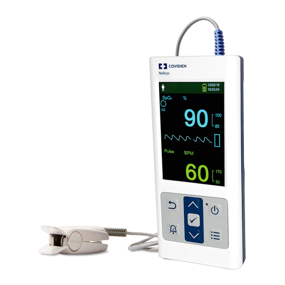
Product Views Product Views Front Panel and Display Components 2.4.1 Front Panel Figure 2-1. Front Panel Components LCD panel (“display” or Use to monitor all graphic and numeric patient information as well as status “screen”) conditions and warning messages. Reference Figure on page 2-4. Up button Press to increase value (such as bpm, alarm volume, or brightness) and to scroll up. -
Page 22: Figure 2-2. Display Components
Product Overview Power-on indicator Is lit green when power is on. Power On/Off button Press and hold to turn on or off the monitoring system. Menu button Press to access menu or to return to the monitoring screen. Display Figure 2-2. Display Components Patient type and patient Reflects the current patient type selected. - Page 23 Product Views Battery status icon Displays the remaining battery capacity. Battery Good — Battery power good. Four green bars appear when • battery is fully charged. The number of green bars decreases as battery power is used. Low Battery — A low priority alarm occurs when the remaining •...
-
Page 24: Table 2-1. Display Colors
Product Overview Interference indicator (Not shown in figure.) Lights when the monitoring system detects degrad- ed quality in the incoming signal. It is common for it to intermittently light as the monitoring system dynamically adjusts the amount of data required for measuring SpO and pulse rate. -
Page 25: Rear Panel
Product Views Rear Panel 2.4.2 Figure 2-3. Rear Panel Components Product and Carton Label Symbols 2.4.3 Table 2-2. Symbol Descriptors Symbol Description Symbol Description Type BF Serial number Prescription only device Date of manufacture Atmospheric pressure limitations Keep dry Humidity limitations Fragile Temperature limitations UL listed Must consult instructions for use CE Mark... - Page 26 Product Overview Table 2-2. Symbol Descriptors (Continued) Symbol Description Symbol Description Reference code (part number) EU representative Protected against foreign objects and Chinese RoHS moisture Proper waste disposal for electrical and Flammable electronic equipment Operator’s Manual...
-
Page 27: Installation
Compact disc (CD) and/or Operator's Manual and Home Use Guide Type AA lithium battery Covidien provides electronic copy of monitoring system manuals on a compact disc for easy access and print- on-demand. Order a printed Nellcor™ portable SpO patient monitoring system Operator’ s Manual or Home Use Guide at no cost or a printed Nellcor™... -
Page 28: Setup
Installation Setup Using the Batteries 3.3.1 WARNING: Explosion hazard — Use only AA size batteries. Do not use a combination of different battery types at the same time. For example, do not use dry batteries and nickel-metal hydride batteries or Lithium-ion batteries together. -
Page 29: Connecting A Nellcor™ Pulse Oximetry Sensor
To connect a Nellcor™ pulse oximetry sensor Select an appropriate compatible Nellcor™ pulse oximetry sensor for the patient and desired application. When selecting a sensor, consider the patient's weight and activity, adequacy of perfusion, availability of sensor sites, need for sterility, and anticipated duration of monitoring. -
Page 30: Figure 3-3. Interface Cable (Optional) Connection To Sensor
Installation If using a DEC-4 interface cable (optional), firmly connect the interface cable to the pulse oximetry sensor. Figure 3-3. Interface Cable (Optional) Connection to Sensor Attach the sensor to the patient. When the monitoring system detects a valid pulse, it enters monitoring mode and displays real- time patient data. -
Page 31: Operation
4 Operation Overview This chapter identifies methods for viewing and collecting patient oxygen saturation data using the Nellcor™ portable SpO patient monitoring system. Operation Basics Power On the Monitoring System 4.2.1 WARNING: If any indicator or display element does not light, or the speaker does not sound, do not use the monitoring system. -
Page 32: Figure 4-1. Example Initial Screen
Operation Figure 4-1. Example Initial Screen Ensure the POST pass tone sounds when POST completes. The POST pass tone functions as an audible confirmation of proper speaker performance. If the speaker does not function, the alarm warning sounds remain inaudible. Once POST is complete, the monitoring screen appears. If a sensor is connected to the patient, SpO pulse readings are displayed, as shown in Figure 4-2. ... -
Page 33: Power Off The Monitoring System
Operation Basics Note: Pressing any button should result in either a valid or an invalid tone. If a button press fails to emit a tone, contact a qualified service technician. Note: Do not use the monitoring system should a repeating, high-pitched alarm tone occur at power on. Instead, contact Technical Services or a qualified service technician. -
Page 34: Menu Structure And Factory Defaults
Operation Menu Structure and Factory Defaults The monitoring system ships with factory default settings. To set different institutional default set- tings, contact a qualified service technician. Table 4-1. Menu Structure and Available Options Factory defaults Item Available selections Adult/pediatric Neonate Alarm Limits Alarm Silence Duration 30, 60, 90, 120 s 120 s... -
Page 35: Patient Monitoring
Patient Monitoring Table 4-1. Menu Structure and Available Options (Continued) Factory defaults Item Available selections Adult/pediatric Neonate Monitoring History View Spot Data Saved spot readings View Continuous Data Intervals of 1, 5, 100, and 500 Clear Monitoring History No, Yes Transfer Data Spot Data By USB By USB... -
Page 36: Figure 4-3. Patient Mode Menu
Operation Scroll to Change Patient Mode and press the OK button. Figure 4-3. Patient Mode Menu Select the appropriate patient mode and pulse oximetry sensor based on body weight. Reference the pulse oximetry sensor Instructions for Use. Adult — For adult and pediatric patients Neonatal —... -
Page 37: Save A Spot Reading
Alarms and Alarm Limits Management Save a Spot Reading 4.4.2 The Save Spot Reading function saves a point in time of the patient’s data. To save a spot reading Press the Menu button. Figure 4-4. Save Spot Reading If it is not already selected, scroll to Save Spot Reading. Press the OK button to select this item. -
Page 38: Table 4-2. Alarm Conditions
Note: If the monitoring system fails to perform as specified, contact Covidien Technical Services, a qualified service technician, or a local supplier for assistance. Operator’s Manual... -
Page 39: Silencing An Audible Alarm
Alarms and Alarm Limits Management Silencing an Audible Alarm 4.5.2 WARNING: If patient safety could be compromised, do not silence the audible alarm or decrease its volume. WARNING: To avoid compromising patient safety, do not cover or obstruct the holes for the speaker. Audible alarm indicators include pitched tones, beeps, and a buzzing sound. -
Page 40: Adjusting Alarm Limits
Operation Adjusting Alarm Limits 4.5.3 WARNING: Prior to each use of the monitoring system, check the alarm limits to ensure they are appropriate for the patient being monitored. Ensure alarm limits do not exceed the standard thresholds set by the institution. -
Page 41: Figure 4-6. Alarm Limits Menu
Alarms and Alarm Limits Management Pulse Rate (PR) numerical area — Displays the pulse rate in beats per minute (bpm). The display value flashes zeros during loss-of-pulse alarms and flashes the pulse rate value on a yellow background when the pulse rate is outside of the alarm limits. During pulse search, the monitoring system continues to update the display. -
Page 42: Using The Satseconds™ Alarm Management System
Operation Press the OK button to select the desired option. For example, Figure shows the High SpO setting selected. Figure 4-7. High SpO Setting Press the up button or down button to change the value. Reference Menu Structure and Factory Defaults on page for adult and neonate limit options. -
Page 43: Additional Patient Modes
Additional Patient Modes Press the Down arrow to change the SatSeconds value to 50, 25, 10, or off (the default value is 100). Press OK to select the value. Figure 4-8. SatSeconds™ Setting Additional Patient Modes In addition to setting the patient mode to Adult or Neonate, patient mode settings include Response mode, Homecare mode, and Sleep Study mode. -
Page 44: Set Homecare Mode
Operation Figure 4-9. Response Mode Menu Press the Up or Down button to highlight Normal or Fast, then press the OK button to confirm the selection. Normal — Responds to changes in blood oxygen saturation within 5 to 7 seconds. • Fast — Responds to changes in blood oxygen saturation within 2 to 4 seconds. This mode can be •... -
Page 45: Figure 4-10. Patient Mode Menu Item
Additional Patient Modes Figure 4-10. Patient Mode Menu Item Press the Up or Down button to highlight the Homecare Mode menu, then press the OK button to select the Homecare Mode menu item. Figure 4-11. Homecare Mode Menu Item Operator’s Manual 4-15... -
Page 46: Figure 4-12. Pass Code Entry For Homecare Mode
Operation Enter the four-digit pass code for Homecare mode. Use the up and down arrows to change the value for each digit, then press the OK button to select the value. Figure 4-12. Pass Code Entry for Homecare Mode After entering the four-digit pass code, select Confirm to enter Homecare mode. When prompted to clear or keep monitoring history, select Yes or No. -
Page 47: Set Sleep Study Mode
Additional Patient Modes The monitoring system is now operating in Homecare mode. Figure 4-14. Homecare Mode Monitoring Screen To return to Standard mode, access the Patient Mode menu again, and enter the pass code for Standard mode. Set Sleep Study Mode 4.6.3 Set the monitoring system to Sleep Study mode when a sleep study will be performed on a patient. -
Page 48: Figure 4-16. Sleep Study Mode Menu Item
Operation Press the Up or Down button to highlight the Sleep Study Mode menu, then press the OK button to select the Sleep Study Mode menu item. Figure 4-16. Sleep Study Mode Menu Item Enter the four-digit pass code for Sleep Study mode. Use the up and down arrows to change the value for each digit, then press the OK button to select the value. -
Page 49: Adjust Brightness And Volume
Adjust Brightness and Volume After entering the four-digit pass code, select Confirm to enter Sleep Study mode. Figure 4-18. Sleep Study Mode When the buttons have not been pressed for 3 minutes, the screen dims. To brighten the screen again, press any button. To return to Standard mode, access the Patient Mode menu again, and enter the password for Standard mode. -
Page 50: Adjust Brightness
Operation Figure 4-19. Device Settings Menu Adjust Brightness 4.7.1 To adjust the brightness of the screen In the Device Settings menu, press the up button or down button to highlight the Brightness Setting menu item and then press the OK button to select the Brightness Setting menu. Figure 4-20. Brightness Setting Menu Press the down button to decrease the brightness. -
Page 51: Adjust Volume
Adjust Brightness and Volume Adjust Volume 4.7.2 To set the desired audible tone volume Press the Menu button. Press the down button to highlight the Device Settings menu and then press the OK button to select the Device Settings menu. Select the Sound Settings menu. -
Page 52: Screen Saver
Schedule regular maintenance and safety checks with a qualified service technician every 24 months. Reference Periodic Safety Checks on page 7-3. In the case of mechanical or functional damage, contact Covidien or a local Covidien representative. Reference Obtaining Technical Assis- tance on page 1-6. -
Page 53: Data Management
5 Data Management Overview This chapter contains information for accessing patient trend data obtained using the Nellcor™ portable SpO patient monitoring system. Trend data can be viewed anytime it is stored in the monitoring system. The monitoring system stores up to 80 hours of trend data. When the monitoring system begins measuring vital signs, it saves data once per second. -
Page 54: Figure 5-1. Monitoring History Menu
Data Management Figure 5-1. Monitoring History Menu From the Monitoring History menu, select View Spot Data or View Continuous Data. Figure 5-2. Monitoring History Screen The View Spot Data screen displays only the readings that were saved using the Save Spot Reading item from the main menu. If the list of readings is longer than one screen, a scroll bar displays on the right edge of the screen. -
Page 55: Table 5-1. Monitoring Status Codes
Monitoring History While viewing Continuous Data, adjust the interval of the displayed readings by pressing OK to display every 1, 5, 100, or 500 data points. The default interval is 100. Figure 5-3. Continuous Data Screen (Interval 100) and Scroll Bar The Status column of the history table will be blank if no errors were present when the data point was recorded. -
Page 56: External Data Communication
Data Management External Data Communication WARNING: Any connections between this monitoring system and other devices must comply with applicable medical systems safety standards such as IEC 60601-1 and applicable collaterals. Failure to do so may result in unsafe leakage current and grounding conditions. ... - Page 57 External Data Communication System Compatibility Prerequisites Windows™* operating system • HyperTerminal™* program or equivalent software installed on PC • Hardware Mini-USB data download cable • CD or thumb drive, if USB driver required • Data transfer by USB port relies on existing communication software drivers for USB-based devices already on the computer, so should not require any modification of the drivers used by the USB interface.
-
Page 58: Figure 5-4. Transfer Data Type
Data Management From the monitoring system’s Transfer Data menu, select Spot Data or Continuous Data. Figure 5-4. Transfer Data Type Select By USB. Figure 5-5. Transfer Data by USB The data is transferred, and a progress bar is displayed. If desired, select Cancel to abort the transmission. The Output Complete message is displayed when the transmission is complete. -
Page 59: Figure 5-6. Sample Trend Data Printout
External Data Communication To interpret downloaded trend data Examine trend data on the HyperTerminal™* program screen, in a spreadsheet, or on a printout from the personal computer. Figure 5-6. Sample Trend Data Printout Product column headings Data source, firmware version, and system settings Patient data column headings Lists appropriate time and data headings Time column... -
Page 60: Figure 5-7. Bridge Driver Installer Window
(CD) into the designated per- sonal computer (PC). Copy the COVIDIEN USB to UART Bridge Driver zip file to the PC, installing it in the desired program folder. Right-click on the zipped folder. Select Extract All. -
Page 61: Figure 5-8. New Hardware Wizard Screen
External Data Communication Figure 5-8. New Hardware Wizard Screen At the prompt from the installer, click on the Next button to copy the driver to the PC. When the installer provides the end-user license agreement, read it carefully, then click the button for accepting the terms of the license. -
Page 62: Figure 5-9. Device Manager Button Under Hardware Tab
Data Management Click the Hardware tab, then the Device Manager button. Figure 5-9. Device Manager Button Under Hardware Tab Select the Ports option from the resulting list. Figure 5-10. Hardware List in Device Manager Window Double click the Silicon Labs CP210x USB to UART Bridge option. 5-10 Operator’s Manual... -
Page 63: Figure 5-11. Sample Initial Usb To Uart Bridge Properties Window
External Data Communication Note: The listed COM port should match the HyperTerminal™* COM port designation. Reference To download trend data using the HyperTerminal™* program on page 5-5. Figure 5-11. Sample Initial USB to UART Bridge Properties Window Click the Port Settings tab. Operator’s Manual 5-11... -
Page 64: Firmware Upgrades
Data Management Set the bits per second to one of four possible baud rates: 19200 or 115200. The factory default is 19200 bps. Figure 5-12. Baud Rate List Under Port Settings Tab Click the OK button to complete the process. Reference To download trend data using the HyperTerminal™* program on page 5-5. -
Page 65: Performance Considerations
6 Performance Considerations Overview This chapter contains information about optimizing the performance of the Nellcor™ portable patient monitoring system. Verify the performance of the monitoring system by following the procedures outlined in the Service Manual. Have a qualified service technician perform these procedures prior to initial instal- lation in a clinical setting. -
Page 66: Patient Conditions
To ensure accurate measurements in bright ambient light, cover the pulse oximetry sensor site with opaque material. Inaccurate Sensor Measurement Conditions A variety of conditions can cause inaccurate Nellcor™ pulse oximetry sensor measurements. Incorrect application of the pulse oximetry sensor •... - Page 67 • Recommended Usage Select an appropriate Nellcor™ pulse oximetry sensor, apply it as directed, and observe all warnings and cautions presented in the Instructions for Use accompanying the sensor. Clean and remove any substances such as nail polish from the application site. Periodically check to ensure that the sensor remains properly positioned on the patient.
-
Page 68: Reducing Emi (Electromagnetic Interference)
Performance Considerations Reducing EMI (Electromagnetic Interference) 6.3.4 Because of the proliferation of radio frequency transmitting equipment and other sources of elec- trical noise in health care environments (for example, electrosurgical units, cellular phones, mobile two-way radios, electrical appliances, and high-definition television), it is possible that high levels of such interference due to close proximity or strength of a source may result in disruption of moni- toring system performance. -
Page 69: Preventive Maintenance
7 Preventive Maintenance Overview This chapter describes the steps required to maintain, service, and properly clean the Nellcor™ portable SpO patient monitoring system. Cleaning WARNING: Remove batteries from the monitoring system before cleaning. WARNING: For reusable sensors, refer to the cleaning instructions in the Instructions for Use for each sensor. -
Page 70: Recycling And Disposal
For sensors, follow cleaning instructions in the instructions for use shipped with those components. Before attempting to clean a Nellcor™ pulse oximetry sensor, read the Instructions for Use enclosed with the sensor. Each sensor model has cleaning instructions specific to that sensor. Follow the pulse oximetry sensor cleaning and disinfecting procedures in the particular sensor's Instructions for Use. -
Page 71: Periodic Safety Checks
Covidien recommends a qualified service technician perform the following checks every 24 months. Inspect the equipment for mechanical and functional damage or deterioration. • Inspect the safety relevant labels for legibility. Contact Covidien or a local Covidien representative, if • labels are damaged or illegible. - Page 72 Preventive Maintenance Page Left Intentionally Blank Operator’s Manual...
-
Page 73: Troubleshooting
8 Troubleshooting Overview This chapter describes how to troubleshoot common problems while using the Nellcor™ portable patient monitoring system. General WARNING: Check the patient's vital signs by alternate means should there be any doubt about the accuracy of any measurement. Request a qualified service technician confirm the monitoring system is functioning correctly. -
Page 74: Error Conditions
Choose alternate site. Loss of Pulse Warm site. Cover sensor. Use forehead, nasal, or ear sensor (adult patient only). Use Nellcor™ adhesive sensor. Secure cable. Secure with headband (MAX-FAST). Remove nail polish. Loosen sensor (too tight). Isolate external interference (electrosurgical device, cell phone). - Page 75 Error Conditions Table 8-1. Common Problems and Resolutions (Continued) Problem Resolution Screen does not function properly Do not use the monitoring system; contact a qualified service technician or Covidien and the power-on beep tones do Technical Services. not sound No sound generation Verify the volume setting is loud enough to hear.
-
Page 76: Return
Obtaining Technical Assistance on page 1-6. Unless otherwise instructed by Covidien, it is not necessary to return the sensor or other accessory items with the monitoring system. Pack the monitoring system in its original shipping carton. If the origi- nal carton is not available, use a suitable carton with the appropriate packing material to protect it during shipping. -
Page 77: Accessories
Performance Considerations page 6-1. The Nellcor™ interface cable connects the monitoring system with the Nellcor™ sensor. Do not attach any cable to the sensor port that is intended for computer use. Use only Covidien-approved sensors and interface cables when connecting to the sensor port. -
Page 78: Nellcor™ Sensor Features
Nellcor™ Sensor Features 9.2.1 Nellcor™ sensor features are different for sensors at a different revision level and by sensor type (adhe- sive, recycled, and reusable). The revision level of a sensor is located on the sensor plug. Biocompatibility Testing 9.2.2... -
Page 79: Optional Equipment
Optional Equipment Optional Equipment The following optional items are available for the monitoring system. Figure 9-1. Standard Protective Covers Figure 9-2. Transport Protective Cover WARNING: To avoid possible shock when using the monitoring system during patient transport, place it in a transport protective cover. It is made of heavier material than the standard protective cover and has a stand for easy viewing of the monitoring screen. - Page 80 Accessories Figure 9-3. Carrying Case Figure 9-4. Extension Cable (DEC-4) Operator’s Manual...
-
Page 81: 10 Theory Of Operations
The monitoring system uses pulse oximetry to measure functional oxygen saturation in the blood. Pulse oximetry works by applying a Nellcor™ sensor to a pulsating arteriolar vascular bed, such as a finger or toe. The sensor contains a dual light source and a photodetector. -
Page 82: Automatic Calibration
Some models of commercially available bench top functional testers and patient simulators can be used to verify the proper functionality of Nellcor™ monitoring systems, sensors, and cables. Refer- ence the individual testing device's operator's manual for the procedures specific to the model of tester used. -
Page 83: Unique Technologies
Unique Technologies Unique Technologies 10.5 Functional versus Fractional Saturation 10.5.1 This monitoring system measures functional saturation where oxygenated hemoglobin is expressed as a percentage of the hemoglobin that can transport oxygen. It does not detect significant amounts of dysfunctional hemoglobin, such as carboxyhemoglobin or methemoglobin. In contrast, hemoxime- ters such as the IL482, report fractional saturation where oxygenated hemoglobin is expressed as a per- centage of all measured hemoglobin, including measured dysfunctional hemoglobins. -
Page 84: Measured Versus Calculated Saturation
Theory of Operations Measured versus Calculated Saturation 10.5.2 When calculating saturation from a blood gas partial pressure of oxygen (PO ), the calculated value may differ from the SpO measurement of a monitoring system. This usually occurs when saturation calculations exclude corrections for the effects of variables such as pH, temperature, the partial pres- sure of carbon dioxide (PCO ), and 2,3-DPG, that shift the relationship between PO and SpO... -
Page 85: System Features
Use Nellcor™ sensors, which are specifically designed for use with the monitoring system. Identify Nellcor™ sensors by the Nellcor™ logo on the plug. All Nellcor™ sensors contain a memory chip car- rying information about the sensor which the monitoring system needs for correct operation, including the sensor’s calibration data, model type, troubleshooting codes, and error detection... -
Page 86: Satseconds™ Alarm Management Parameter
Theory of Operations SatSeconds™ Alarm Management Parameter 10.6.2 The monitoring system monitors the percentage of hemoglobin binding sites saturated with oxygen in the blood. With traditional alarm management, upper and lower alarm limits are set to alarm at specific SpO levels. - Page 87 System Features First SpO Event Consider the first event. Suppose the SatSeconds™ alarm limit is set to 25. The patient’s SpO drops to 79% and the duration of the event is 2 seconds before saturation again exceeds the lower alarm threshold of 85%.
- Page 88 Theory of Operations Second SpO Event Consider the second event. Suppose the SatSeconds™ alarm limit is still set to 25. The patient’s SpO drops to 84% and the duration of the event is 15 seconds before saturation again exceeds the lower alarm threshold of 85%.
- Page 89 System Features Third SpO Event Consider the third event. Suppose the SatSeconds™ alarm limit is still set to 25. During this event, the patient’s SpO drops to 75%, which is 10% below the lower alarm threshold of 85%. Since the patient’s saturation does not return to a value over the lower alarm threshold within 2.5 seconds, an alarm sounds.
- Page 90 Theory of Operations Page Left Intentionally Blank 10-10 Operator’s Manual...
-
Page 91: 11 Product Specifications
11 Product Specifications Overview 11.1 This chapter contains physical and operational specifications of the Nellcor™ portable SpO patient monitoring system. Ensure all product requirements are met prior to installation of the monitoring system. Physical Characteristics 11.2 Enclosure Weight 274 g (0.604 lbs), including four batteries Dimensions 70 mm W x 156 mm H x 32 mm D (2.76 in W x 6.14 in H x 1.26 in D) -
Page 92: Electrical
Product Specifications Electrical 11.3 Battery Four new lithium batteries with 3,000 mAh will typically provide 20 hours of monitoring with no external communication, no audible alarm sound, display backlight set to 25% brightness, and at an ambient temperature of 25° C. Type Lithium AA Voltage... -
Page 93: Tone Definition
Tone Definition Tone Definition 11.5 Table 11-2. Tone Definitions Tone category Description High priority alarm tone Volume level Adjustable (level 1-4) Pitch (± 20Hz) 540 Hz Pulse width (± 20msec) 175 msec (IEC60601-1-8) Number of pulses in burst 10, interburst interval of 4 sec (IEC60601-1-8) Repetitions Continually Medium priority alarm tone... -
Page 94: Sensor Accuracy And Ranges
Product Specifications Table 11-2. Tone Definitions (Continued) Tone category Description POST pass tone Volume level Not changeable Pitch (± 20Hz) 600 Hz Pulse width (± 20msec) 500 msec Number of pulses Repetitions No repeat Sensor Accuracy and Ranges 11.6 Table 11-3. Trends Types Tabular Memory Saves total 80 hours data events Saves date and time, alarm conditions,... -
Page 95: Sound Pressure
Power Dissipation 52.5 mW Saturation accuracy varies by sensor type. Refer to the Sensor Accuracy Grid at www.covidien.com/rms. Accuracy specifications were validated using measurements of healthy non-smoking adult volunteers during controlled hypoxia studies spanning the specified saturation ranges. Subjects were recruited from the local population and comprised both men and women ranging in age from 18-50 years old, and spanned a range of skin pigmentations. -
Page 96: Product Compliance
Product Specifications Product Compliance 11.8 Standards Compliance EN IEC 60601-1: Edition 3.1 EN IEC 60601-1-2: Edition 3.0 and 4.0 EN IEC 60601-1-6: Edition 3.1 EN IEC 60601-1-8: Edition 2.1 EN IEC 60601-1-11: Edition 2.0 EN ISO 80601-2-61: Edition 1.0 CAN/CSA C22.2 No. 60601-1:14 3rd Edition ANSI/AAMI ES 60601-1:2005/(R)2012 Equipment Classifications Type of Protection against electric shock... -
Page 97: Electromagnetic Compatibility (Emc)
(1) this device may not cause harmful interference, and (2) this device must accept any inter- ference received, including interference that may cause undesired operation. Any changes or modifications to this equipment not expressly approved by Covidien may cause harmful radio fre- quency interference and void your authority to operate this equipment. -
Page 98: Table 11-7. Electromagnetic Immunity Guidelines And Compliance
Product Specifications Table 11-6. Electromagnetic Emissions Guidelines and Compliance (Continued) Guidance and manufacturer’s declaration—Electromagnetic emissions (IEC/EN 60601-1-2) The monitoring system is intended for use in the electromagnetic environment specified below. The cus- tomer or the user of the monitoring system should assure that it is used in such an environment. Emissions test Compliance Electromagnetic environment guidance... -
Page 99: Table 11-8. Recommended Separation Distance Calculations
Manufacturer’s Declaration Table 11-8. Recommended Separation Distance Calculations Guidance and manufacturer’s declaration—Electromagnetic immunity (IEC/EN 60601-1-2) The monitoring system is intended for use in the electromagnetic environment specified below. The customer or the user of the monitoring system should assure that it is used in such an environment. Immunity test IEC/EN 60601-1-2 Compliance level... -
Page 100: Table 11-9
Product Specifications Table 11-9. Test Specifications for Enclosure Port Immunity to RF Wireless Communications Equipment Test Band (MHz) Service Modulation Max. power Distance (m) Immunity test frequency level (V/m) (MHz) 380 to 390 TETRA 400 Pulse modulation 18 Hz 430 to 470 GMRS 460, FRS 460 ±... -
Page 101: Sensor And Cable Compliance
Item Maximum length Sensors Nellcor™ adult SpO sensor, reusable (nonsterile) DS100A 3.0 ft. (0.9 m) Nellcor™ adult XL SpO sensor (sterile, single-use only) MAX-AL 3.0 ft. (0.9 m) Nellcor™ forehead SpO sensor (sterile, single-use only) MAX-FAST 2.5 ft (0.75 m) Operator’s Manual... -
Page 102: Safety Tests
Product Specifications Table 11-11. Sensor and Cable Length Item Maximum length Nellcor™ neonatal-adult SpO sensor (sterile, single-use only) MAX-N Nellcor™ infant SpO sensor (sterile, single-use only) MAX-I Nellcor™ pediatric SpO sensor (sterile, single-use only) MAX-P 1.5 ft. (0.5 m) Nellcor™ adult SpO... -
Page 103: Essential Performance
Essential Performance Table 11-13. Patient Leakage Current Specification Patient leakage current Test condition Allowable leakage current Normal Condition (NC) 100 μA Essential Performance 11.10 Per IEC 60601-1 and ISO 80601-2-61, the monitoring system’s essential performance attributes include: and pulse rate accuracy — Reference Sensor Accuracy and Ranges on page 11-4. - Page 104 Product Specifications Page Left Intentionally Blank 11-14 Operator’s Manual...
-
Page 105: A Clinical Studies
A Clinical Studies Overview This appendix contains data from clinical studies conducted for the Nellcor™ sensors used with the Nellcor™ portable SpO patient monitoring system. One (1) prospective, controlled hypoxia clinical study was conducted to demonstrate the accura- cy of Nellcor™ sensors when used in conjunction with the Nellcor™ portable SpO patient moni- toring system. -
Page 106: Study Population
108-250 Very light Olive Skin pigment Dark olive/Medium black Extremely dark/Blue black Study Results Accuracy was calculated using the root mean square difference (RMSD). Table A-2. SpO Accuracy for Nellcor™ Sensors vs. CO-oximeters MAX-A MAX-N MAX-FAST decade Data Arms Data Arms Data... -
Page 107: Adverse Events Or Deviations
Adverse Events or Deviations Figure A-1. Modified Bland-Altman Plot Test Sensor; Avg CO-oximeter value 70-100% SpO Avg CO-oximeter value 70-100% SpO Oximetry board with MAX-A sensor Trendline of MAX-A sensor Oximetry board with MAX-N sensor Trendline of MAX-N sensor Oximetry board with MAX-FAST sensor Trendline of MAX-FAST sensor Adverse Events or Deviations The study was conducted as expected with no adverse events and no deviations from the protocol. - Page 108 Clinical Studies Page Left Intentionally Blank Operator’s Manual...
- Page 109 Accessory equipment ........1-5 Nellcor™ pulse oximetry sensor Electromagnetic compatibility and measurement accuracy .
- Page 110 Index Essential performance ........11-13 Manufacturer’s declaration ....... . .11-6 Physical characteristics .
- Page 112 Part No. PT00106388 Rev A (A7328-3) 2019-07 © 2018 Covidien. All rights reserved. Covidien llc 15 Hampshire Street, Mansfield, MA 02048 USA. Covidien Ireland Limited, IDA Business & Technology Park, Tullamore, Ireland. www.covidien.com [T] 1.800.635.5267...
Need help?
Do you have a question about the Nellcor and is the answer not in the manual?
Questions and answers
Какой пароль от сервисного меню
How do you reset the date and time once the button battery has been replaced.