Table of Contents
Advertisement
Quick Links
Advertisement
Table of Contents
Troubleshooting

Subscribe to Our Youtube Channel
Related Manuals for Covidien WarmTouch


Summary of Contents for Covidien WarmTouch
- Page 1 Service Manual WarmTouch™ Convective Warming Unit...
- Page 2 COVIDIEN, COVIDIEN with logo, and Covidien logo are U.S. and internationally registered trademarks of Covidien AG. Other brands are trademarks of a Covidien company. ©2013 Covidien.
-
Page 3: Table Of Contents
....... . .2-2 2.2.4 Covidien WarmTouch™ Warming Blankets ....2-2 2.3 Product Views... - Page 4 4 Operation ..........4-1 4.1 Overview .
- Page 5 7.5 Performance Tests ........7-3 7.5.1 Power-On Test .
- Page 6 10.13 Power Supply Replacement ......10-43 10.14 Power Supply Output Cable Replacement ....10-46 10.15 Ground Cable Replacement .
- Page 7 .........14-1 14.2 Returning the Warming Unit to Covidien .
- Page 8 Page Left Intentionally Blank Service Manual...
- Page 9 Figures 1 Introduction Figure 1-1 Serial Number Label on Back of Warming Unit ... .1-9 Figure 1-2 Menu Screen ........1-10 Figure 1-3 System Information Screen .
- Page 10 Figure 5-9 Menu Screen ........5-10 Figure 5-10 Filter Information Screen .
- Page 11 Figure 10-3 Removing the Keypad ......10-5 Figure 10-4 Feeding the Keypad Cable Through the Access Slot ..10-6 Figure 10-5 Aligning the Keypad .
- Page 12 11 Internal Component Replacement (Inside Rear Enclosure) Figure 11-1 Thermistor Sensor Assembly ......11-3 Figure 11-2 Thermistor Wire and Rivet ......11-4 Figure 11-3 Thermistor Cable Connections .
- Page 13 Figure 11-41 USB Port ........11-44 Figure 11-42 Filter Enclosure and Screws .
- Page 14 Figure 12-26 Securing the Hose Duct Adapter ....12-29 Figure 12-27 USB Connector in Rear Enclosure ....12-30 Figure 12-28 Thermistor Cable Secured .
-
Page 15: Introduction
1 Introduction Overview This manual, for use by qualified personnel only, contains instructions for servicing, testing, and maintaining the Covidien WarmTouch™ Convective Warming Unit. The manual includes all information necessary for troubleshooting problems with the warming unit and replacing affected components, including parts lists, replacement procedures, and system diagrams. -
Page 16: Safety Information
Introduction Safety Information This section lists safety information associated with the warming unit. Where appropriate in the manual, individual Warnings and Cautions are repeated as reminders. Please familiarize yourself with this safety information before ser- vicing the warming unit. For reference, additional Warnings and Cautions that apply to operating the warming system in the clinical environment are provided in Warnings (Patient Treatment) -
Page 17: Cautions (Service)
Safety Information WARNING: No modification of this equipment is allowed. Modification can result in death, injury, or property damage. WARNING: Before attempting to open or disassemble the warming unit, disconnect the power cord from the AC power source. ... -
Page 18: Warnings (Patient Treatment)
Possible explosion hazard. Do not use the device in the presence of flammable anesthetics or in an oxygen-rich environment. WARNING: No free-hosing. Keep hose nozzle connected to a WarmTouch™ blanket at all times or thermal injury may occur. WARNING: Possible burn or infection hazard. - Page 19 WARNING: Use WarmTouch™ blankets only as directed. Carefully follow the Instructions for Use provided with the blankets regarding proper handling and positioning. ...
-
Page 20: Cautions (Patient Treatment)
Caution: Only use WarmTouch™ blankets with the WarmTouch warming unit. Do not attempt to use other types of blankets with the warming unit. Similarly, do not attempt to use WarmTouch blankets with other types of warming units. Caution: The USB port on the warming unit is for service use by qualified personnel only. -
Page 21: Esd (Electrostatic Discharge) Precautions
ESD (Electrostatic Discharge) Precautions ESD (Electrostatic Discharge) Precautions Caution: Observe ESD (electrostatic discharge) precautions when servicing the warming unit. To avoid damaging ESD-sensitive components while service the warming unit, follow all appropriate ESD guidelines. These guidelines include: Using an ESD wrist strap, properly connected to a reliable ground. •... - Page 22 Introduction Medium flat-blade screwdriver with long handle • Knife, box cutter, or similar tool with a thin, stiff blade • Wire cutters • Small knife or scissors • Cable ties • Strap or cable tie to wrap around handle of unit and hose duct adapter •...
-
Page 23: Serial Number, Software Version, And Error Codes
Serial Number, Software Version, and Error Codes Serial Number, Software Version, and Error Codes Prior to servicing the warming unit, note the unit’s serial number, software version, and any error codes. The serial number is located on the back of the warming unit (Figure 1-1). -
Page 24: Figure 1-2 Menu Screen
Introduction Figure 1-2. Menu Screen Press the System Information key. The System Information screen shows the software version and the most recent error messages, if any (Figure 1-3). Figure 1-3. System Information Screen Software Version Error Messages (Up to Six) Note: Time stamps associated with error messages do not necessarily reflect local time. The warming unit is set to UTC (Coordinated Universal Time) at manufacture. -
Page 25: Component Disposal - Weee Directive
Component Disposal - WEEE Directive Component Disposal - WEEE Directive The warming unit contains components that must be disposed of in accordance with WEEE Directive. Do not dispose of the warming unit as a whole or the following individual components as unsorted municipal waste: Power cord –... -
Page 26: Labeling Symbols
Label By prescription only No Free Hosing: Hose nozzle must be connected to a WarmTouch™ blanket or thermal injury may occur. Do not use during magnetic resonance imaging (MRI). Degree of protection from electric shock: Protection Class I, Type BF applied part... - Page 27 Labeling Symbols Table 1-3. Symbols on the Warming Unit and Shipping Label (Continued) Symbol Description Appears On... Warming Shipping Unit Label Temperature limitations (operating): +18°C to +28°C Relative humidity limitations (shipping/storage): 10% to 95% (non-condensing) Relative humidity limitations (operating): 15% to 85% (non-condensing) Atmospheric pressure limitations (shipping/storage): 12 kPa to 106 kPa...
-
Page 28: Obtaining Technical Assistance
For technical assistance or to order parts and additional manuals, contact Covi- dien Technical Services or a local Covidien representative. When contacting Covidien for troubleshooting or service issues, please provide the information described in Serial Number, Software Version, and Error Codes on page 1-9. - Page 29 Obtaining Technical Assistance Covidien Technical Services (Continued) Covidien Danmark A/S Covidien Deutschland Covidien ECE GmbH Galvaniho 7/a Langebrogade 6E, 4. sal 821 04 Bratislava 1411 København K Technisches Service Center Slovakia Danmark Raffineriestr. 18 Tel.: +421 248 214 573 Tel +45 702 753 50...
- Page 30 Introduction Covidien Technical Services (Continued) Covidien Norge AS Covidien Panama Covidien Polska Postboks 343 Parque Industrial Costa del Esta Al. Jerozolimskie 162 1372 Asker. Calle Primera, Edifio # 109 Warszawa. 02-342 Norway Panama City, Panama Polska Tel +47 668 522 22...
-
Page 31: Related Documents
• document provides instructions for operating the WarmTouch warming system in a clinical environment. Instructions for Use - Covidien WarmTouch™ Warming Blanket — This document, • provided with WarmTouch warming blankets, contains important information regarding intended use, handling, connection, and positioning of the blanket. - Page 32 Introduction Page Left Intentionally Blank 1-18 Service Manual...
-
Page 33: Product Overview
2 Product Overview Overview This chapter provides an introduction to the Covidien WarmTouch™ Convec- tive Warming System, including information about its features and controls. Product Description The warming system provides a means for treating or preventing hypothermia in adult and pediatric patients in clinical settings. The warming system consists of an electronic blower (warming unit) that delivers heated air through a flex- ible hose to a lightweight blanket placed on the patient. -
Page 34: Indications For Use
None known. Covidien WarmTouch™ Warming Blankets 2.2.4 The Covidien WarmTouch™ Convective Warming Unit is designed for use with WarmTouch™ blankets only. WarmTouch blankets are designed to attach securely to the warming unit’s hose nozzle. The nozzle features guides and a clip to ensure correct orientation. -
Page 35: Product Views
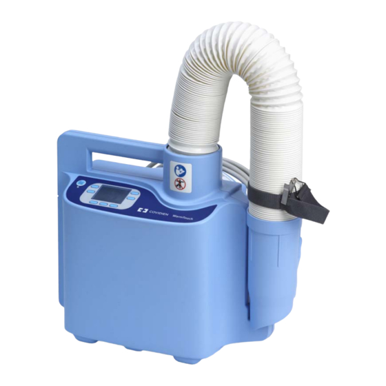
Product Views Product Views Front View 2.3.1 Figure 2-1. Front View Operator’s Panel Hose Handle Nozzle Strap with Clip No Free-Hosing Label Nozzle Service Manual... -
Page 36: Back View
Product Overview Back View 2.3.2 Figure 2-2. Back View No Free-Hosing Label Mounting Channel (x2) Serial Number Label Pole Clamp (x3) Symbols Label Bed Hook USB Port (Under Cover) Power Cord Service Manual... -
Page 37: Operator's Panel
Operator’s Panel Operator’s Panel The operator’s panel includes an On/Standby key, a multi-functional keypad, and a display that provides temperature and status information. The display indicates the function of each adjacent key. Key functions change based on operating context, as described in subsequent chapters. Figure 2-3. Operator’s Panel On/Standby Key –... - Page 38 Product Overview Animated arrow indicates that the temperature is adjusting upward or downward to a new setting. The symbol disappears when the tem- perature is within 1.5°C of the new setting. Menu Key – Press to access screens for viewing filter status and system informa- tion.
-
Page 39: Installation
3 Installation Overview This chapter contains information for installing the Covidien WarmTouch™ Convective Warming Unit. Safety Reminders WARNING: The use of accessories or cables with the warming system other than those indicated in this manual may result in non-compliance with the specifications... -
Page 40: Attaching The Power Cord
Installation Attaching the Power Cord The warming unit is shipped with a power cord appropriate to the country of use. To attach the power cord: Position the warming unit on its front so the bottom of the unit is accessible (Figure 3-2). -
Page 41: Figure 3-2 Power Cord Connection
Attaching the Power Cord Figure 3-2. Power Cord Connection Set the warming unit upright. Wrap the power cord around the back of the unit, and secure it with the attached strap (Figure 3-3). Service Manual... -
Page 42: Figure 3-3 Power Cord Wrapped And Secured
Installation Figure 3-3. Power Cord Wrapped and Secured Service Manual... -
Page 43: Installing The Warming Unit
Installing the Warming Unit Installing the Warming Unit The warming unit can be used as a standalone device, or it can be mounted on an IV pole, bed, or optional transport cart. The following sections provide mounting instructions. IV Pole Installation 3.4.1 The warming unit can be mounted on an IV pole with a maximum diameter of 3.2 cm (1.25 inches) and a minimum diameter of 1.9 cm (0.75 inches). -
Page 44: Figure 3-4 Back View
Installation Figure 3-4. Back View Mounting Channel Clamp Knob (x2) Clamp Foot (x2) Bracing the IV pole, position the warming unit against the pole so that the pole is fully seated in the mounting channel. Verify that the handle is not above the maximum height.Reference Figure 3-5 on page 3-7. -
Page 45: Figure 3-5 Warming Unit Mounted On Iv Pole
Installing the Warming Unit Figure 3-5. Warming Unit Mounted on IV Pole Service Manual... -
Page 46: Bed Installation
Installation Bed Installation 3.4.2 The warming unit can be attached to a bed that has a mounting surface up to 3.6 cm (1.4 inches) wide. Typically, the unit is attached to the bed’s head board or foot board. To attach the warming unit to a bed: Locate the bed hook on the back of the warming unit. -
Page 47: Cart Installation
Installing the Warming Unit Cart Installation 3.4.3 An optional transport cart is available for the warming unit. Contact Covidien Technical Services or a local Covidien representative to purchase the transport cart. Reference Obtaining Technical Assistance on page 1-14. To install the warming unit on the cart: Ensure that the power cord is secured at the back of the warming unit. -
Page 48: Figure 3-8 Cart Mounting Peg And Warming Unit Mounting Hole
Installation Locate the mounting pegs on the cart’s vertical poles, and locate the holes at the bottom of the warming unit’s mounting channels. Figure 3-8. Cart Mounting Peg and Warming Unit Mounting Hole Mounting Channel (x2) Mounting Peg (x2) Mounting Hole (x2) Holding the warming unit by the handle and bracing the cart, position the warming unit against the cart so that the mounting holes engage the mounting pegs. -
Page 49: Figure 3-9 Warming Unit Mounted On Cart
Installing the Warming Unit Figure 3-9. Warming Unit Mounted on Cart Service Manual 3-11... - Page 50 Installation Page Left Intentionally Blank 3-12 Service Manual...
-
Page 51: Operation
4 Operation Overview This chapter provides basic operating instructions for the Covidien Warm- Touch™ Convective Warming Unit. Full instructions for operating the unit in a clinical setting are provided in the Covidien WarmTouch™ Convective Warming System Operator’s Manual. Clinicians intending to use the warming system for treatment of patients must consult the Operator’s Manual. -
Page 52: Applying Power
Operation Applying Power WARNING: Possible electric shock hazard. Grounding reliability can be achieved only when the warming unit is connected to a suitable mains outlet with protective earth grounding. To apply power to the warming unit: Locate a hospital-grade or suitable mains outlet with protective earth grounding. Ensure that the power outlet is easily accessible;... -
Page 53: Overview Of Warming Unit Operating Modes
Overview of Warming Unit Operating Modes Overview of Warming Unit Operating Modes Standby Mode • Status LED: AMBER • Heater: OFF • Fan: OFF • Display: OFF Ready Mode • Status LED: GREEN • Heater: OFF • Fan: OFF • Display: ON Treatment Mode •... -
Page 54: Beginning Operation
Operation Beginning Operation To begin operation: Press the On/Standby key. The unit enters Ready mode: The status LED turns green, and the display turns on. • A short tone indicates a successful power-on self-test (POST). If POST is unsuc- • cessful, an alarm screen appears. -
Page 55: Controlling The Temperature
Replace Filter screen reappears at each subsequent power- Controlling the Temperature Note: During patient treatment, a WarmTouch™ warming blanket must be attached to the warming unit at all times. Select a setting by pressing one of the temperature keys. Change the setting as desired. -
Page 56: Using Boost Mode
Operation Figure 4-3. Warming System Set to 40°C (Medium) Note that when you change the temperature setting, an amber arrow appears next to the current temperature while it adjusts. When the temperature is within approximately 1.5°C of the new setting, the arrow disappears. Using Boost Mode 4.6.1 Boost mode allows rapid warming of patients. -
Page 57: Using The Heat Off Setting
Controlling the Temperature Using the Heat Off Setting 4.6.2 The heat off setting provides a means to cool a patient. To use the heat off setting, press the Heat Off key. Air is delivered to the warming blanket at room temperature (heater off). Figure 4-5. Warming System Set to Heat Off Returning to Ready Mode 4.6.3... -
Page 58: Returning To Standby Mode
Operation Returning to Standby Mode 4.6.4 Use Standby mode when you are finished using the warming system but do not wish to unplug it. To return to Standby mode during operation, press the On/Standby key. The heater and fan shut off, the display goes blank, and the status LED turns amber. -
Page 59: Maintenance
5 Maintenance Overview This chapter describes the cleaning and maintenance requirements for the Covidien WarmTouch™ Convective Warming Unit. Cleaning the Warming Unit Page 5-2 Safety Checks Page 5-3 Filter Replacement Page 5-4 Monitoring the Filter Status Page 5-10 Safety Reminders ... -
Page 60: Cleaning The Warming Unit
Maintenance Cleaning the Warming Unit WARNING: Clean the warming unit after each use, as described in this manual. WARNING: Disconnect the warming unit's power cord from the AC power source before performing this procedure. Caution: Do not spray, pour, or spill any liquid on the warming unit, its accessories, connectors, switches, or openings in the case. -
Page 61: Safety Checks
Safety Checks Safety Checks Physical Inspection 5.4.1 Covidien recommends that the customer perform a visual check of the follow- ing items before each use of the warming unit: Equipment — Inspect the warming unit and power cord for mechanical damage •... -
Page 62: Filter Replacement
Maintenance Filter Replacement WARNING: Do not operate the warming unit with the filter enclosure removed. WARNING: Disconnect the warming unit's power cord from the AC power source before performing this procedure. Caution: The HEPA filter must be replaced every 2,000 hours of operation or 365 days, whichever comes first. -
Page 63: Figure 5-2 Filter Enclosure And Power Cord Connection
Filter Replacement Requirements: WT HEPA Filter Kit (page A-7) • Torque driver with #2 Phillips bit • 70% isopropyl alcohol solution and soft cloth (if replacing gasket in filter enclo- • sure) To replace the filter: If the power cord is secured around the back of the unit, unwind it completely. Position the warming unit on its front so the bottom of the unit is accessible (Figure 5-2). -
Page 64: Figure 5-3 Hepa Filter
Maintenance Remove the three screws from the filter enclosure. Lift the enclosure away from the unit, disengaging the power cord from its socket. Set the enclosure and attached power cord aside. Caution: The institution should follow local governing ordinances and recycling instructions regarding disposal or recycling of filter and device components or end of life of the product. -
Page 65: Figure 5-4 Gasket Inside Filter Enclosure
Filter Replacement Before placing the filter enclosure back on the unit, check the circular gasket inside the enclosure (Figure 5-4). If the gasket is worn or damaged, replace it as follows: Peel the gasket off the enclosure. Use a soft cloth dampened with a solution of 70% isopropyl alcohol to remove any adhesive remnants from the surface. -
Page 66: Figure 5-6 Filter Information Screen - Filter Expired
Maintenance Set the unit upright, and plug the power cord into the power outlet. Reset the filter counters as follows: Press the On/Standby key. The Replace Filter screen appears (Figure 5-5). Figure 5-5. Replace Filter Screen Press the Replace Filter key. The Filter Information screen appears (Figure 5- Figure 5-6. Filter Information Screen - Filter Expired Press the Filter Reset key. -
Page 67: Figure 5-7 Main Screen At Power-On
Filter Replacement Figure 5-7. Main Screen at Power-On Power off the warming unit by pressing the On/Standby key. Disconnect the power cord from the outlet. Wrap the power cord around the back of the unit, and secure it with the attached strap (Figure 5-8). -
Page 68: Monitoring The Filter Status
Maintenance Monitoring the Filter Status The warming unit monitors filter usage and provides counters that indicate the number of operating hours and days until the filter needs to be replaced. You can anticipate filter replacement by checking the counters on the Filter Infor- mation screen. -
Page 69: Figure 5-10 Filter Information Screen
Monitoring the Filter Status Figure 5-10. Filter Information Screen Filter Days Remaining Filter Hours Remaining To return to the Main screen, press the Exit key twice. Service Manual 5-11... - Page 70 Maintenance Page Left Intentionally Blank 5-12 Service Manual...
-
Page 71: Troubleshooting
6 Troubleshooting Overview This chapter provides information for troubleshooting problems that may occur with the Covidien WarmTouch™ Convective Warming Unit. Principles of Operation Page 6-2 Basic Troubleshooting Page 6-9 Alarms Page 6-12 Safety Reminders WARNING: No modification of this equipment is allowed. Modification can result in death, injury, or property damage. -
Page 72: Principles Of Operation
Principles of Operation Overview 6.3.1 The Covidien WarmTouch™ Convective Warming System provides clinicians with a means to supply warmed or room temperature air to the skin surface of patients to achieve and maintain normothermia. The system consists of the Covidien WarmTouch™ Convective Warming Unit and specially designed blankets to distribute the air. -
Page 73: Block Diagram
Principles of Operation Block Diagram 6.3.2 Figure 6-1 shows the relationship between the major components in the warming unit. Descriptions of the components and their interactions follow. A detailed diagram of the cable connections between the components is provid- ed on page 6-8. -
Page 74: Component Descriptions
USB Port To facilitate software updates, error log downloads, and other service tasks performed at Covidien Service Centers, the warming unit can communicate with a computer via its USB interface. The USB port is located under a protec- tive cover at the back of the unit (see Figure 10-18 on page 10-23). - Page 75 The replaceable battery for the RTC is located on the UI PCBA. The USB connector on the UI PCBA supports software updates, error log downloads, and other service functions performed at Covidien Service Centers. Power PCBA...
- Page 76 Troubleshooting Power Supply The power supply is located inside the front enclosure (Figure 10-31 page 10-43). It is an internally-fused AC/DC converter delivering 48VDC, 65W output from an input range of 90-264VAC. It has an input connection from the AC power inlet, an output connection to the power PCBA, and a ground connection to the equipotential stud.
- Page 77 Principles of Operation Thermostat The thermostat is located in the hose duct adapter near the base of the hose (see Figure 11-9 on page 11-10). It is connected to the power PCBA. The ther- mostat provides thermal cut-out protection by opening at 49°C to 55°C (120°F to 131°F), resulting in heater and fan shutdown.
-
Page 78: Component Cable Connections
Troubleshooting Component Cable Connections 6.3.4 Figure 6-2. Cable Connections Between Major Components Service Manual... -
Page 79: Basic Troubleshooting
Basic Troubleshooting Basic Troubleshooting Table 6-1. Warming Unit Problems and Resolutions Problem Resolution Low-priority alarm Alarms on page 6-12. Medium-priority alarm (flashing) Failure to power on Check the power cord’s connection to the warming unit. The • (LED not turning on) connector must be fully seated (page 3-2). - Page 80 Troubleshooting Table 6-1. Warming Unit Problems and Resolutions (Continued) Problem Resolution Display not working Make sure that the On/Standby key has been pressed and the • status LED is green. (If the status LED is amber, the display is blank.) Check the display cable connection to the UI PCBA (page 10-8).
-
Page 81: Figure 11-1 Thermistor Sensor Assembly
Basic Troubleshooting Table 6-1. Warming Unit Problems and Resolutions (Continued) Problem Resolution Heater not operating Check the error codes on the System Information screen • (page 1-9), and perform recommended corrective actions (page B-1). Check the heater cable connection to the power PCBA •... -
Page 82: Alarms
Troubleshooting Alarms If an alarm condition or error occurs during operation, the warming unit sounds alarm tones and displays an alarm screen. There are two types of alarms: low-priority and medium-priority. Figure 6-3. Low-Priority Alarm (Left) and Medium-Priority Alarm (Right) Table 6-2. Alarm Indicators Symbol Tones Type of Alarm... - Page 83 Alarms To troubleshoot an alarm: If the alarm is currently indicated on the unit’s display, try clearing the alarm as follows: Power off the warming unit by pressing the key indicated on the alarm screen. Press the On/Standby key to power the warming unit back on. Note: While a low-priority alarm may be cleared this way, a medium-priority alarm typically will not be cleared.
- Page 84 Troubleshooting Page Left Intentionally Blank 6-14 Service Manual...
-
Page 85: Performance Verification
7 Performance Verification Overview This chapter provides instructions for testing the Covidien WarmTouch™ Con- vective Warming Unit after repair. Testing is required after most service proce- dures. Refer to the instructions in each component replacement section for minimum testing requirements. -
Page 86: Required Test Equipment
Performance Verification Required Test Equipment Temperature probe (either handheld meter or USB-based): • Accuracy of probe must be ±0.25°C or better over the range 10°C to 60°C. – Probe cable must be long enough to reach from computer to hose duct –... -
Page 87: Performance Tests
Performance Tests Performance Tests Power-On Test Page 7-3 Keypad Test Page 7-5 Display Test Page 7-7 Temperature Accuracy Test Page 7-8 Flow Test Page 7-10 Thermostat Test Page 7-11 Note: A test data sheet that can be used to record test results is provided on page C-2. -
Page 88: Figure 7-2 Main Screen At Power-On
Performance Verification Figure 7-2. Main Screen at Power-On Figure 7-3. Replace Filter Screen at Power-On Press one of the temperature keys. Verify that the temperature reading on the screen rises and stabilizes. When finished with all testing: Press the On/Standby key to power off the unit. Unplug the unit from the outlet. -
Page 89: Keypad Test
Performance Tests Keypad Test 7.5.2 Use the keypad test to confirm that each key is functioning and that the unit responds as expected. To perform the keypad test: Perform steps 1 and 2 of the power-on test (page 7-3). Press and verify each key: Expected Behavior of Unit Temperature reading on Main screen rises and stabilizes. - Page 90 Performance Verification Expected Behavior of Unit Main screen appears: (Exit) Unit powers off: - Display: OFF (On/Standby) - Status LED: AMBER When finished with all testing, unplug the unit from the outlet. Keypad Test Failure If the test fails, see Basic Troubleshooting on page 6-9.
-
Page 91: Display Test
Performance Tests Display Test 7.5.3 Use the display test to confirm that there are no bad pixels. To perform the display test: Plug the warming unit’s power cord into the outlet, and press the On/Standby key. Verify that the initial display screen is lighted white and has no vertical or horizontal black or colored rows. -
Page 92: Temperature Accuracy Test
Performance Verification Temperature Accuracy Test 7.5.4 Use the temperature accuracy test to verify that the unit’s output air tempera- ture is within specification. Requirements: Temperature probe (see page 7-2). • To perform the temperature accuracy test: Perform steps 1 and 2 of the power-on test (page 7-3). - Page 93 Performance Tests Lower the temperature probe into the hose until it contacts the metal screen at the base of the hose duct adapter. The probe should be approximately centered on the screen. Test the 34°C setting: Press the 34°C key. Allow the temperature to stabilize for at least 3 minutes. Confirm that the temperature measured by the probe is within 1°C of the temperature setting.
-
Page 94: Flow Test
Performance Verification Flow Test 7.5.5 Use the flow test to confirm fan functionality. To perform the flow test: Position the hose on the nozzle hook with the hose compressed as much as pos- sible (Figure 7-5). Figure 7-5. Position of Hose for Flow Test Perform steps 1 and 2 of the power-on test (page 7-3). -
Page 95: Thermostat Test
Performance Tests Thermostat Test 7.5.6 Use the thermostat test to verify that the thermostat opens when an over-tem- perature condition occurs and that an audible and visual alarm is generated. To perform the thermostat test: Perform steps 1 and 2 of the power-on test (page 7-3). -
Page 96: Figure 7-8 Select Test Screen
Performance Verification Press the key code as described in Service Screen Access on page 7-2. The Select Test screen appears (Figure 7-8). Figure 7-8. Select Test Screen Press the Test Thermostat key to begin the thermostat test. The Thermostat Test screen appears (Figure 7-9). - Page 97 Performance Tests Press the System Information key. The System Information screen shows the most recent error messages. Look for error code 006, indicating that the thermal cut-out switch opened. When finished with all testing: Press the On/Standby key to power off the unit. Unplug the unit from the outlet.
-
Page 98: Electrical Safety Tests
Performance Verification Electrical Safety Tests This section provides values for electrical safety tests required by the warming unit. Technicians must be familiar with the standards applicable to their respec- tive institution and country. Test equipment and its application must comply with the applicable standards. -
Page 99: External Component Replacement
8 External Component Replacement Overview This chapter provides instructions for replacing external components of the Covidien WarmTouch™ Convective Warming Unit. Pole Clamp Replacement Page 8-2 USB Port Cover Replacement Page 8-4 Power Cord Replacement Page 8-5 Nozzle Replacement Page 8-8... -
Page 100: Pole Clamp Replacement
External Component Replacement Pole Clamp Replacement This procedure describes replacing pole clamps only, not the mounting bolts for the clamps. If you are replacing the mounting bolts, refer to Pole Clamp and Mounting Bolt Replacement on page 11-18. Figure 8-1. Pole Clamps Requirements: WT-CWU Pole Clamp Kit (page... -
Page 101: Figure 8-2 Pole Clamp Foot And Knob
Pole Clamp Replacement To replace a pole clamp: At the back of the unit, completely loosen the knob on the clamp to be replaced, and remove it from the mounting bolt (Figure 8-2). Figure 8-2. Pole Clamp Foot and Knob Clamp Foot (x3) Clamp Knob (x3) Slide the clamp foot off the bolt. -
Page 102: Usb Port Cover Replacement
External Component Replacement USB Port Cover Replacement Figure 8-3. USB Port Cover Requirements: WT-CWU USB Port Cover Kit (page A-2) • Torque driver with #2 Phillips bit • WARNING: Disconnect the warming unit's power cord from the AC power source before performing this procedure. -
Page 103: Power Cord Replacement
Power Cord Replacement Power Cord Replacement WARNING: The use of accessories or cables with the warming system other than those indicated in this manual may result in non-compliance with the specifications listed in Electromagnetic Compatibility (EMC) on page 13-4. The power cord requires proper disposal in accordance with WEEE Directive. - Page 104 External Component Replacement Requirements: WarmTouch power cord (page A-2) • WARNING: Disconnect the warming unit's power cord from the AC power source before performing this procedure. To replace the power cord: If the power cord is secured around the back of the unit, unwind it completely.
-
Page 105: Figure 8-5 Power Cord Wrapped And Secured
Power Cord Replacement Figure 8-5. Power Cord Wrapped and Secured Service Manual... -
Page 106: Nozzle Replacement
External Component Replacement Nozzle Replacement Figure 8-6. Nozzle Requirements: WT-CWU Nozzle Kit (page A-2) • Medium flat-blade screwdriver with long handle • WARNING: Disconnect the warming unit's power cord from the AC power source before performing this procedure. Service Manual... -
Page 107: Figure 8-7 Nozzle Clips
Nozzle Replacement To replace the nozzle: Locate the four clips inside the nozzle that secure it to the hose (Figure 8-7). Figure 8-7. Nozzle Clips Nozzle Clip (x4) Flange Insert the screwdriver into the nozzle, positioning the blade between one of the clips and the surface of the nozzle. -
Page 108: Nozzle Strap With Clip Replacement
External Component Replacement Nozzle Strap with Clip Replacement Figure 8-8. Nozzle Strap with Clip Requirements: WT Nozzle Strap/Clip Kit (page A-2) • WARNING: Disconnect the warming unit's power cord from the AC power source before performing this procedure. To replace the nozzle strap with clip: Lift the nozzle off the hook on the side of the warming unit. -
Page 109: No Free-Hosing Label Replacement
No Free-Hosing Label Replacement No Free-Hosing Label Replacement The front enclosure and nozzle must display the no free-hosing label (Figure 8- 9). If either of these labels is damaged or becomes unreadable, it must be replaced. Figure 8-9. No Free-Hosing Labels on Front Enclosure (L) and Nozzle (R) Requirements: WT No Free-Hosing Label Kit (page... - Page 110 External Component Replacement To replace a no free-hosing label: Peel off the old label. Use a soft cloth dampened with a solution of 70% isopropyl alcohol to remove any adhesive remnants from the surface. After the surface is completely dry, remove the backing from the new label. Position the label as shown in Figure 8-9 on page 8-11.
-
Page 111: Accessing The Inside Of The Warming Unit
9 Accessing the Inside of the Warming Unit Overview This chapter provides instructions for accessing components inside the Covid- ien WarmTouch™ Convective Warming Unit. Note: Testing is required after service procedures that involve accessing the inside of the warming unit. Refer to the instructions in each component replacement section for minimum testing requirements. -
Page 112: Separating The Front And Rear Enclosures
Accessing the Inside of the Warming Unit Separating the Front and Rear Enclosures Figure 9-1. Separated Enclosures Requirements: Torque driver with #2 Phillips bit • WARNING: Disconnect the warming unit's power cord from the AC power source before performing this procedure. To separate the front and rear enclosures: If the power cord is secured around the back of the unit, unwind it completely. -
Page 113: Figure 9-2 Power Cord Connection
Separating the Front and Rear Enclosures Figure 9-2. Power Cord Connection Power Cord Routing Bracket Power Cord Connector Optional Step: Disengage the power cord from its routing bracket and remove it from the socket. Remove the seven screws securing the rear enclosure to the front enclosure (Figure 9-3). -
Page 114: Figure 9-3 Enclosure Screws
Accessing the Inside of the Warming Unit Figure 9-3. Enclosure Screws Supporting both enclosures, reposition the unit on its back. Caution: The front and rear enclosures are connected by cables. When separating the enclosures, do not apply stress to the cables. Carefully lift the front enclosure at the nozzle hook and rotate it away from the rear enclosure. -
Page 115: Rejoining The Front And Rear Enclosures
Rejoining the Front and Rear Enclosures Rejoining the Front and Rear Enclosures Requirements: Torque driver with #2 Phillips bit • Caution: When rejoining the front and rear enclosures, ensure that no cables are caught between them. To rejoin the front and rear enclosures: Carefully rotate the front enclosure onto the rear enclosure, tucking the cables into the rear enclosure as follows (Figure... -
Page 116: Figure 9-5 Power Cord Connection
Accessing the Inside of the Warming Unit Note: If the power cord is attached to the rear enclosure, check its alignment with the socket while positioning the front enclosure. Make sure that the power cord is fully seated in the socket when the enclosures are together. Align all edges of the enclosures, making sure they are fully seated and that no cables are caught between them. -
Page 117: Figure 9-6 Power Cord Wrapped And Secured
Rejoining the Front and Rear Enclosures Set the warming unit upright. Perform all required tests for the component being replaced. (Each component replacement procedure lists testing requirements.) Wrap the power cord around the back of the unit, and secure it with the provided strap (Figure 9-6). - Page 118 Accessing the Inside of the Warming Unit Page Left Intentionally Blank Service Manual...
-
Page 119: Figure 10-15 Ribbon Cable
10 Internal Component Replacement (Inside Front Enclosure) Overview 10.1 This chapter provides instructions for replacing components that require accessing the inside of the Covidien WarmTouch™ Convective Warming Unit’s front enclosure. Keypad Replacement Page 10-3 Display (LCD) Replacement Page 10-8 User Interface (UI) PCBA Replacement... -
Page 120: Internal Component Replacement (Inside Front Enclosure)
Internal Component Replacement (Inside Front Enclosure) Safety Reminders 10.2 WARNING: No modification of this equipment is allowed. Modification can result in death, injury, or property damage. WARNING: Before attempting to open or disassemble the warming unit, disconnect the power cord from the AC power source. -
Page 121: Keypad Replacement
Keypad Replacement Keypad Replacement 10.3 Figure 10-1. Keypad Requirements: WT-CWU Keypad Kit (page A-3) • Torque driver with #2 Phillips bit • Knife, box cutter, or similar tool with a thin, stiff blade • 70% isopropyl alcohol solution and soft cloth • Strap or cable tie to wrap around handle of unit •... -
Page 122: Figure 10-2 Keypad Cable Connection On Ui Pcba
Internal Component Replacement (Inside Front Enclosure) To replace the keypad: Follow the procedure Separating the Front and Rear Enclosures on page 9-2. On the UI PCBA, slide the locking bar up from the J204 connector, and disconnect the keypad cable (Figure 10-2). -
Page 123: Figure 10-3 Removing The Keypad
Keypad Replacement Figure 10-3. Removing the Keypad Use a soft cloth dampened with a solution of 70% isopropyl alcohol to remove any adhesive remnants from the surface. Make sure that the surface is completely dry before proceeding. Remove the clear window film and protective paper from the back of the new keypad. -
Page 124: Figure 10-4 Feeding The Keypad Cable Through The Access Slot
Internal Component Replacement (Inside Front Enclosure) Figure 10-4. Feeding the Keypad Cable Through the Access Slot Align the keypad with the top edge of the recess, and press the top edge of the keypad against the recess (Figure 10-5). Rub the keypad downward towards the bottom edge across its full width to engage the adhesive, taking care to eliminate any air from the seal. -
Page 125: Figure 10-6 Keypad Cable Secured By Locking Bar
Keypad Replacement Place the unit on its back. Remove the strap or cable tie from the handle, and re- open the unit. On the UI PCBA, slide the locking bar up from the J204 connector, and slide the keypad cable completely into the connector in front of the locking bar. Press down on both sides of the locking bar to secure the cable. -
Page 126: Display (Lcd) Replacement
Internal Component Replacement (Inside Front Enclosure) Display (LCD) Replacement 10.4 The display requires proper disposal in accordance with WEEE Directive. Do not dispose of this item as unsorted municipal waste. Figure 10-7. Display behind UI PCBA Requirements: WT-CWU Display Kit (page A-3) •... -
Page 127: Figure 10-8 Display Cable Connection On Ui Pcba
Display (LCD) Replacement To replace the display: Follow the procedure Separating the Front and Rear Enclosures on page 9-2. On the UI PCBA, lift the locking tab at the J207 connector, and disconnect the display cable. Leave the remaining cables attached to the PCBA (Figure 10-8). -
Page 128: Figure 10-9 Positioning The Display
Internal Component Replacement (Inside Front Enclosure) Leave the nylon spacer on each mounting screw. Caution: The institution should follow local governing ordinances and recycling instructions regarding disposal or recycling of filter and device components or end of life of the product. Lift the display out of its window. - Page 129 Display (LCD) Replacement Position the PCBA on the mounting screws with the USB cable at the top. Make sure that the display cable isn’t caught behind the PCBA. Make sure that the shoulder washers are in place in the PCBA mounting holes, with the bottom of the shoulder against the top surface of the PCBA.
-
Page 130: User Interface (Ui) Pcba Replacement
Internal Component Replacement (Inside Front Enclosure) User Interface (UI) PCBA Replacement 10.5 The UI PCBA and the battery on the PCBA require proper disposal in accordance with WEEE Directive. Do not dispose of these items as unsorted municipal waste. Figure 10-10. UI PCBA Requirements: WT-CWU UI PCBA Kit (page... - Page 131 User Interface (UI) PCBA Replacement WARNING: Disconnect the warming unit's power cord from the AC power source before performing this procedure. To replace the UI PCBA: Follow the procedure Separating the Front and Rear Enclosures on page 9-2. Disconnect the cables from the UI PCBA as follows (Figure 10-11): Slide the locking bar up from the J204 connector, and disconnect the keypad...
-
Page 132: Figure 10-11 Ui Pcba Connections
Internal Component Replacement (Inside Front Enclosure) Figure 10-11. UI PCBA Connections Keypad Cable Ribbon Cable (J204 Connection) (P204 Connection) USB Cable Display Cable (J203 Connection) (J207 Connection) Nut, Lock Washer, Shoulder Washer (x2) Remove the UI PCBA from its mounting screws as follows: Remove the nut from each mounting screw. -
Page 133: Figure 10-12 Usb Connection On Ui Pcba
User Interface (UI) PCBA Replacement Detach the USB cable from the J203 connector as follows (Figure 10-12): Carefully cut the cable tie securing the USB cable. Remove the cable tie and USB backing plate. Disconnect the USB cable. Figure 10-12. USB Connection on UI PCBA Cable Tie Backing Plate ... -
Page 134: Figure 10-13 Attaching Backing Plate And Cable Tie To Ui Pcba
Internal Component Replacement (Inside Front Enclosure) Attach the USB cable to the new UI PCBA as follows (Figure 10-13): Place the backing plate against the non-component side of the PCBA, cover- ing the notch at the top of the board. Align the holes in the backing plate with the holes on each side of the notch. - Page 135 User Interface (UI) PCBA Replacement Attach the UI PCBA to the mounting screws as follows: Make sure that the display is still seated in the display window. Make sure that the nylon spacers are still on the mounting screws. Position the PCBA on the mounting screws with the USB cable at the top. Make sure that the display cable and keypad cable aren’t caught behind the PCBA.
-
Page 136: Figure 10-14 Keypad Cable Secured By Locking Bar
Internal Component Replacement (Inside Front Enclosure) Figure 10-14. Keypad Cable Secured by Locking Bar Follow the procedure Rejoining the Front and Rear Enclosures on page 9-5. Perform the following tests: Keypad Test on page 7-5. Display Test on page 7-7. Electrical Safety Tests on page 7-14. -
Page 137: Ribbon Cable Replacement
Ribbon Cable Replacement Ribbon Cable Replacement 10.6 Figure 10-15. Ribbon Cable Requirements: WT-CWU Ribbon Cable Kit (page A-3) • Torque driver with #2 Phillips bit • WARNING: Disconnect the warming unit's power cord from the AC power source before performing this procedure. Service Manual 10-19... -
Page 138: Figure 10-16 Ribbon Cable Connections
Internal Component Replacement (Inside Front Enclosure) To replace the ribbon cable: Follow the procedure Separating the Front and Rear Enclosures on page 9-2. On the UI PCBA, open the locking ears at the P204 connector, and disconnect the ribbon cable (Figure 10-16). - Page 139 Ribbon Cable Replacement Follow the procedure Rejoining the Front and Rear Enclosures on page 9-5. Perform the following tests: Power-On Test on page 7-3. Electrical Safety Tests on page 7-14. Service Manual 10-21...
-
Page 140: Usb Cable Replacement
Internal Component Replacement (Inside Front Enclosure) USB Cable Replacement 10.7 Figure 10-17. USB Cable Requirements: WT-CWU USB Micro AB Cable Kit (page A-3) • Torque driver with #1 and #2 Phillips bits and 11/32” hex socket • Wire cutters • 1 cable tie •... -
Page 141: Figure 10-18 Usb Port
USB Cable Replacement To replace the USB cable: At the back of the unit, loosen the screw securing the cover over the USB port, and rotate the cover aside (Figure 10-18). Do not remove the cover. Figure 10-18. USB Port USB Connector Screw (x2) USB Port Cover Remove the two screws securing the USB cable connector to the enclosure. -
Page 142: Figure 10-19 Ui Pcba Connections
Internal Component Replacement (Inside Front Enclosure) Figure 10-19. UI PCBA Connections Keypad Cable Ribbon Cable (J204 Connection) (P204 Connection) USB Cable Display Cable (J203 Connection) (J207 Connection) Nut, Lock Washer, Shoulder Washer (x2) Remove the UI PCBA from its mounting screws as follows: Remove the nut from each mounting screw. -
Page 143: Figure 10-20 Usb Connection On Ui Pcba
USB Cable Replacement Detach the USB cable from the J203 connector as follows (Figure 10-20): Cut the cable tie securing the USB cable. Remove the cable tie and set the USB backing plate aside. Disconnect the USB cable. Figure 10-20. USB Connection on UI PCBA Cable Tie Backing Plate Attach the new USB cable to the UI PCBA as follows... -
Page 144: Figure 10-21 Attaching Backing Plate And Cable Tie To Ui Pcba
Internal Component Replacement (Inside Front Enclosure) From the back of the PCBA, insert the cable tie through the opposite hole in the backing plate to the front of the PCBA. Connect the USB cable to the J203 connector. Figure 10-21. Attaching Backing Plate and Cable Tie to UI PCBA Adjust the cable tie so that the lock is snug against the PCBA. - Page 145 USB Cable Replacement Attach the UI PCBA to the mounting screws as follows: Make sure that the display is still seated in the display window. Make sure that the nylon spacers are still on the mounting screws. Position the PCBA on the mounting screws with the USB cable at the top. Make sure that the display cable and keypad cable aren’t caught behind the PCBA.
-
Page 146: Figure 10-22 Keypad Cable Secured By Locking Bar
Internal Component Replacement (Inside Front Enclosure) Figure 10-22. Keypad Cable Secured by Locking Bar Position the connector on the other end of the USB cable in the port inside the rear enclosure, with the connector paddle toward the bottom of the enclosure (Figure 10-17 on page 10-22). -
Page 147: Clock Battery Replacement
Clock Battery Replacement Clock Battery Replacement 10.8 The battery requires proper disposal in accordance with WEEE Directive. Do not dispose of this item as unsorted municipal waste. Figure 10-23. Clock Battery on UI PCBA Requirements: 3V CR 2032, lithium-ion coin-cell battery • Torque driver with #2 Phillips bit •... - Page 148 Internal Component Replacement (Inside Front Enclosure) To replace the battery: Follow the procedure Separating the Front and Rear Enclosures on page 9-2. Using a non-metallic stylus or similar tool, carefully push the battery up from the bottom of its holder on the UI PCBA until you can grasp the battery and remove it. ...
-
Page 149: Power Pcba Replacement
Power PCBA Replacement Power PCBA Replacement 10.9 The Power PCBA requires proper disposal in accordance with WEEE Directive. Do not dispose of this item as unsorted municipal waste. Figure 10-24. Power PCBA Requirements: WT-CWU Power PCBA Kit (page A-3) • Torque driver with #2 Phillips bit •... - Page 150 Internal Component Replacement (Inside Front Enclosure) To replace the Power PCBA: Follow the procedure Separating the Front and Rear Enclosures on page 9-2. Disconnect the cables from the Power PCBA as follows (Figure 10-25): Disconnect the AC power inlet wire assembly from the 6-pin P112 connector. Disconnect the power supply output cable from the 4-pin P109 connector.
-
Page 151: Figure 10-25 Power Pcba Connections
Power PCBA Replacement Figure 10-25. Power PCBA Connections Heater Cable Ribbon Cable (P114 Connection) (P101 Connection) AC Power Inlet Wire Assembly Thermistor Cable (P112 Connection) (P108 Connection) Power Supply Output Cable Fan Cable (P109 Connection) (P111 Connection) Speaker Cable Thermostat Cable (P103 Connection) (P113 Connection) Remove the four screws securing the Power PCBA to the enclosure. - Page 152 Internal Component Replacement (Inside Front Enclosure) Dispose of the Power PCBA as required by WEEE Directive. Position the new Power PCBA on the four mounting bosses, with the P101 con- nector toward the UI PCBA (Figure 10-25 on page 10-33). Attach the Power PCBA to the mounting bosses with the four screws.
-
Page 153: Fuse Replacement
Fuse Replacement Fuse Replacement 10.10 Figure 10-26. Fuses on Power PCBA Requirements: WT-CWU Fuse Kit (page A-3) or Littlefuse 0218010; 250 V, 10 A fuse (or equiva- • lent) Torque driver with #2 Phillips bit • Note: Each kit contains five fuses. ... - Page 154 Internal Component Replacement (Inside Front Enclosure) To replace the fuse(s): Follow the procedure Separating the Front and Rear Enclosures on page 9-2. Locate and remove the blown fuse(s) on the Power PCBA. Insert the new fuse(s). Follow the procedure Rejoining the Front and Rear Enclosures on page 9-5.
-
Page 155: Speaker Replacement
Speaker Replacement Speaker Replacement 10.11 Figure 10-27. Speaker Requirements: WT-CWU Speaker Kit (page A-3) • Torque driver with #2 Phillips bit • WARNING: Disconnect the warming unit's power cord from the AC power source before performing this procedure. Service Manual 10-37... -
Page 156: Figure 10-28 Speaker Cable Connections
Internal Component Replacement (Inside Front Enclosure) To replace the speaker: Follow the procedure Separating the Front and Rear Enclosures on page 9-2. Disconnect the two speaker wires from the speaker. Remove the four screws securing the speaker to the enclosure, and remove the speaker. - Page 157 Speaker Replacement Perform the following tests: Power-On Test on page 7-3. Listen for the POST tone to verify speaker opera- tion. Electrical Safety Tests on page 7-14. Service Manual 10-39...
-
Page 158: Speaker Cable Replacement
Internal Component Replacement (Inside Front Enclosure) Speaker Cable Replacement 10.12 Figure 10-29. Speaker Cable Requirements: WT-CWU Speaker Cable Kit (page A-4) • Torque driver with #2 Phillips bit • WARNING: Disconnect the warming unit's power cord from the AC power source before performing this procedure. -
Page 159: Figure 10-30 Speaker Cable Connections
Speaker Cable Replacement To replace the speaker cable: Follow the procedure Separating the Front and Rear Enclosures on page 9-2. Disconnect the two speaker cable connections from the speaker terminal (Figure 10-30). On the Power PCBA, disconnect the speaker cable from the 2-pin P103 connector. Figure 10-30. Speaker Cable Connections Positive (+) Terminal Negative (–) Terminal... - Page 160 Internal Component Replacement (Inside Front Enclosure) Perform the following tests: Power-On Test on page 7-3. Listen for the POST tone to verify the speaker cable connection. Electrical Safety Tests on page 7-14. 10-42 Service Manual...
-
Page 161: Power Supply Replacement
Power Supply Replacement Power Supply Replacement 10.13 The power supply requires proper disposal in accordance with WEEE Directive. Do not dispose of this item as unsorted municipal waste. Figure 10-31. Power Supply Requirements: WT-CWU Pwr Supply Kit (page A-4) • Torque driver with #1 and #2 Phillips bits •... -
Page 162: Figure 10-32 Power Supply Connections
Internal Component Replacement (Inside Front Enclosure) To replace the power supply: Follow the procedure Separating the Front and Rear Enclosures on page 9-2. Disconnect the cables from the power supply as follows (Figure 10-32): Disconnect the ground cable from the GND terminal. Disconnect the AC power inlet wire assembly from the 3-pin CON1 connector. - Page 163 Power Supply Replacement Remove the four screws securing the power supply to the enclosure. Caution: The institution should follow local governing ordinances and recycling instructions regarding disposal or recycling of filter and device components or end of life of the product. Dispose of the power supply as required by WEEE Directive.
-
Page 164: Power Supply Output Cable Replacement
Internal Component Replacement (Inside Front Enclosure) Power Supply Output Cable Replacement 10.14 Figure 10-33. Power Supply Output Cable Requirements: WT-CWU P/S Output Cable Kit (page A-4) • Torque driver with #2 Phillips bit • WARNING: Disconnect the warming unit's power cord from the AC power source before performing this procedure. -
Page 165: Figure 10-34 Power Supply Output Cable Connections
Power Supply Output Cable Replacement To replace the power supply output cable: Follow the procedure Separating the Front and Rear Enclosures on page 9-2. Disconnect the power supply output cable from the 4-pin P109 connector on the Power PCBA and from the 4-pin CON2 connector on the power supply (Figure 10- 34). -
Page 166: Ground Cable Replacement
Internal Component Replacement (Inside Front Enclosure) Ground Cable Replacement 10.15 Figure 10-35. Ground Cable GND Terminal Equipotential Stud (Power Supply) Ground Cable Requirements: WT-CWU Ground Cable Kit (page A-4) • Torque driver with #2 Phillips bit and 10mm hex socket • 10-48 Service Manual... -
Page 167: Figure 10-36 Ground Cable Terminal On Equipotential Stud
Ground Cable Replacement WARNING: Disconnect the warming unit's power cord from the AC power source before performing this procedure. To replace the ground cable: Follow the procedure Separating the Front and Rear Enclosures on page 9-2. Disconnect the ground cable from the GND terminal on the power supply (Figure 10-35 on page 10-48). - Page 168 Internal Component Replacement (Inside Front Enclosure) Attach the new ground cable to the equipotential stud as follows: Place the ground cable terminal on the stud. Place the lock washer on top of the terminal. Place the nut on top of the lock washer. Tighten the nut to 3.2 to 3.8 N-m (28.3 to 33.6 lb-in).
-
Page 169: Ac Power Inlet Replacement
AC Power Inlet Replacement AC Power Inlet Replacement 10.16 Figure 10-37. AC Power Inlet Requirements: WT-CWU AC Inlet Kit (page A-4) • Torque driver with #1 and #2 Phillips bits and 10mm hex socket • 10 mm open-end or box wrench • Wire cutters and cable tie (some warming unit configurations) •... -
Page 170: Figure 10-38 Ac Power Inlet Connections
Internal Component Replacement (Inside Front Enclosure) To replace the AC power inlet assembly: Follow the procedure Separating the Front and Rear Enclosures on page 9-2. Disconnect the AC power inlet wire assembly from the 6-pin P112 connector on the Power PCBA and from the 3-pin CON1 connector on the power supply (Figure 10-38). -
Page 171: Figure 10-39 Equipotential Stud Connections
AC Power Inlet Replacement Disconnect the AC power inlet ground cable from the equipotential stud as follows (Figure 10-39): Remove the top nut from the threaded end of the stud. Remove the lock washer and lift the power supply ground cable terminal off the stud. - Page 172 Internal Component Replacement (Inside Front Enclosure) Connect the AC power inlet wire assembly as follows (Figure 10-38 page 10-52): Connect the 6-pin connector to P112 on the Power PCBA. Make sure that the connector is oriented as shown in Figure 10-38, and that it is fully seated.
-
Page 173: Equipotential Stud Replacement
Equipotential Stud Replacement Equipotential Stud Replacement 10.17 Figure 10-40. Equipotential Stud Requirements: WT-CWU Equipotential Stud Kit (page A-4) • Torque driver with #2 Phillips bit and 10mm hex socket • 10 mm open-end or box wrench • Ohmmeter or digital multi-meter with resistance function •... -
Page 174: Figure 10-41 Equipotential Stud Connections
Internal Component Replacement (Inside Front Enclosure) To replace the equipotential stud: Follow the procedure Separating the Front and Rear Enclosures on page 9-2. Remove the equipotential stud as follows (Figure 10-41): Remove the top nut from the threaded end of the stud. Remove the lock washer and lift the power supply ground cable terminal off the stud. -
Page 175: Figure 10-42 Equipotential Stud And Washer
Equipotential Stud Replacement From the bottom of the enclosure, insert the threaded end of the stud into the hole (Figure 10-42). Figure 10-42. Equipotential Stud and Washer Connect the cables to the equipotential stud as follows (Figure 10-41 page 10-56): Place the AC power inlet ground cable terminal on the threaded end of the stud. Place a lock washer on top of the terminal. - Page 176 Internal Component Replacement (Inside Front Enclosure) Page Left Intentionally Blank 10-58 Service Manual...
- Page 177 11 Internal Component Replacement (Inside Rear Enclosure) Overview 11.1 This chapter provides instructions for replacing components that require accessing the inside of the Covidien WarmTouch™ Convective Warming Unit’s rear enclosure. Thermistor Sensor Assembly Replacement Page 11-3 Thermostat Replacement Page 11-9...
-
Page 178: Internal Component Replacement (Inside Rear Enclosure)
Internal Component Replacement (Inside Rear Enclosure) Safety Reminders 11.2 WARNING: No modification of this equipment is allowed. Modification can result in death, injury, or property damage. WARNING: Before attempting to open or disassemble the warming unit, disconnect the power cord from the AC power source. -
Page 179: Thermistor Sensor Assembly Replacement
Thermistor Sensor Assembly Replacement Thermistor Sensor Assembly Replacement 11.3 Figure 11-1. Thermistor Sensor Assembly Thermistor Wire and Rivet Thermistor Cable Connection (Power PCBA) Thermistor Cable Requirements: WT-CWU Thermistor Sens Assy Kit (page A-5) • Torque driver with #2 Phillips bit • Wire cutters •... -
Page 180: Figure 11-2 Thermistor Wire And Rivet
Internal Component Replacement (Inside Rear Enclosure) WARNING: Disconnect the warming unit's power cord from the AC power source before performing this procedure. Caution: The thermistor is very delicate and easily damaged. Use extreme care when working with the thermistor sensor assembly. To replace the thermistor sensor assembly: Follow the procedure Separating the Front and Rear Enclosures... -
Page 181: Figure 11-3 Thermistor Cable Connections
Thermistor Sensor Assembly Replacement Carefully cut and remove the cable tie securing the thermistor cable to the fan cable. Disconnect the thermistor cable from the 2-pin P108 connector on the Power PCBA. Remove the thermistor sensor assembly from the unit. Figure 11-3. Thermistor Cable Connections Cable Tie and Tie Mount Cable Tie... -
Page 182: Figure 11-4 Attaching Rivet To Thermistor Wire
Internal Component Replacement (Inside Rear Enclosure) Figure 11-4. Attaching Rivet to Thermistor Wire Caution: Be careful when moving the hose duct adapter. The connected thermistor wire can break if too much stress is applied to it. Position the thermistor in the hose duct adapter as follows (Figure 11-5): Make sure that the portion of wire between the rivet and the tip of the therm-... -
Page 183: Figure 11-6 Thermistor Position Inside Hose Duct Adapter
Thermistor Sensor Assembly Replacement Lift the hose duct adapter away from the fan duct just enough to see inside the adapter. Make sure that the tip of the thermistor is no more than 0.3 cm (1/8 inch) from the center hub of the duct adapter (Figure 11-6). - Page 184 Internal Component Replacement (Inside Rear Enclosure) Position the thermistor cable against the tie mount on the enclosure as shown in Figure 11-2 on page 11-4. Secure the cable with a cable tie and trim the end of the cable tie. Connect the thermistor cable to the 2-pin connector at P108 on the Power PCBA (Figure 11-3 on page 11-5).
-
Page 185: Thermostat Replacement
Thermostat Replacement Thermostat Replacement 11.4 Figure 11-8. Thermostat Requirements: WT-CWU Thermostat Kit (page A-5) • Torque driver with #2 Phillips bit • Small flat-blade screwdriver • WARNING: Disconnect the warming unit's power cord from the AC power source before performing this procedure. Service Manual 11-9... -
Page 186: Figure 11-9 Thermostat Cable Connection To Thermostat
Internal Component Replacement (Inside Rear Enclosure) To replace the thermostat: Follow the procedure Separating the Front and Rear Enclosures on page 9-2. Detach the thermostat cable from the two terminals on the thermostat (Figure 11- Figure 11-9. Thermostat Cable Connection to Thermostat Thermostat Thermostat Cable Terminal (x2) -
Page 187: Figure 11-10 Thermostat Rivets (Outside Of Hose Duct Adapter)
Thermostat Replacement Remove the rivets and thermostat. Figure 11-10. Thermostat Rivets (Outside of Hose Duct Adapter) Thermostat Rivet (x2) Rivet Pin (x2) Attach the new thermostat to the hose duct adapter as follows (Figure 11-11): From the inside of the hose duct adapter, insert the terminal side of the ther- mostat through the hole in the duct adapter. -
Page 188: Figure 11-11 Thermostat Rivets (Inside Of Hose Duct Adapter)
Internal Component Replacement (Inside Rear Enclosure) Figure 11-11. Thermostat Rivets (Inside of Hose Duct Adapter) Thermostat Rivet (x2) Rivet Pin (x2) Place the hose duct adapter back into the fan duct by inserting the top edge of the adapter first, then rotating the adapter downward until it drops into place (Figure 11-12). - Page 189 Thermostat Replacement Connect the two thermostat wires to the new thermostat as shown in Figure 11- on page 11-10. Note that the wires can be connected to either terminal, but for consistency across units they should be connected as shown. Make sure that thermostat cable is routed as shown in Figure 11-8 on page 11-9.
-
Page 190: Thermostat Cable Replacement
Internal Component Replacement (Inside Rear Enclosure) Thermostat Cable Replacement 11.5 Figure 11-13. Thermostat Cable Thermostat Cable Connection Thermostat Cable Routing Tabs (to Thermostat) Thermostat Cable Thermostat Cable Connection (Power PCBA) Requirements: WT-CWU Thermostat Cable Kit (page A-5) • Torque driver with #2 Phillips bit •... -
Page 191: Figure 11-14 Thermostat Cable Connection To Power Pcba
Thermostat Cable Replacement WARNING: Disconnect the warming unit's power cord from the AC power source before performing this procedure. To replace the thermostat cable: Follow the procedure Separating the Front and Rear Enclosures on page 9-2. Disconnect the thermostat cable from the 2-pin P113 connector on the Power PCBA (Figure 11-14). -
Page 192: Figure 11-15 Thermostat Cable Connection To Thermostat
Internal Component Replacement (Inside Rear Enclosure) Disconnect the thermostat cable from the two terminals on the thermostat (Figure 11-15). Figure 11-15. Thermostat Cable Connection to Thermostat Thermostat Thermostat Cable Terminal (x2) Connect the new thermostat cable to the two terminals. Note that the wires can be connected to either terminal, but for consistency across units they should be connected as shown in Figure... - Page 193 Thermostat Cable Replacement Using two cable ties, secure the thermostat cable to the heater cable as follows (Figure 11-14 on page 11-15): Place one cable tie around the cables approximately 5 cm (2 inches) from where the heater cable exits below the fan assembly. Place the other cable tie around the cables approximately 10 cm (4 inches) from the heater cable connector (P114) on the Power PCBA.
-
Page 194: Pole Clamp And Mounting Bolt Replacement
Internal Component Replacement (Inside Rear Enclosure) Pole Clamp and Mounting Bolt Replacement 11.6 This procedure describes replacing the pole clamps and the mounting bolts for the clamps. If you are replacing the pole clamps only, refer to Pole Clamp Replacement on page 8-2. -
Page 195: Figure 11-17 Pole Clamp Foot And Knob
Pole Clamp and Mounting Bolt Replacement To replace a pole clamp and mounting bolt: At the back of the unit, completely loosen the knob on the clamp to be replaced. Remove the knob and clamp foot from the mounting bolt (Figure 11-17). -
Page 196: Figure 11-18 Pole Clamp Mounting Bolt
Internal Component Replacement (Inside Rear Enclosure) Figure 11-18. Pole Clamp Mounting Bolt Install the new mounting bolt by placing the bolt into its mounting hole and press- ing downward until fully seated. Follow the procedure Rejoining the Front and Rear Enclosures on page 9-5. Slide the new clamp foot onto the bolt, making sure that the rubber pad is toward the unit. -
Page 197: Hose Replacement
Hose Replacement Hose Replacement 11.7 Figure 11-19. Hose Hose Hose Duct Adapter Requirements: WT-CWU Hose Kit (page A-5) • Torque driver with #2 Phillips bit • Medium flat-blade screwdriver with long handle • Pliers • Small knife or scissors • Service Manual 11-21... -
Page 198: Figure 11-20 Wire Attaching Hose To Hose Duct Adapter
Internal Component Replacement (Inside Rear Enclosure) WARNING: Disconnect the warming unit's power cord from the AC power source before performing this procedure. To replace the hose: Remove the nozzle strap from the hose and set it aside. (Reference Nozzle Strap with Clip Replacement on page 8-10.) Follow the procedure... -
Page 199: Figure 11-21 Inserting Hose Duct Adapter
Hose Replacement Follow the procedure Nozzle Replacement on page 8-8 to remove the nozzle from the end of the old hose and install it on the new hose. Note: Replacement of the No Free-Hosing label on the nozzle does not apply in this case. On the new hose, find the end of the reinforcing wire in the hose and trim around the wire so that approximately 1.6 cm (5/8 inch) is free of the hose material. - Page 200 Internal Component Replacement (Inside Rear Enclosure) Perform the following tests: Power-On Test on page 7-3. Electrical Safety Tests on page 7-14. 11-24 Service Manual...
-
Page 201: Hose Duct Adapter Replacement
Hose Duct Adapter Replacement Hose Duct Adapter Replacement 11.8 Figure 11-22. Hose Duct Adapter Requirements: WT-CWU Hose Duct Adapter Kit (page A-5) • Torque driver with #2 Phillips bit • Small flat-blade screwdriver • Pliers • WARNING: Disconnect the warming unit's power cord from the AC power source before performing this procedure. -
Page 202: Figure 11-23 Thermistor Wire And Rivet
Internal Component Replacement (Inside Rear Enclosure) To replace the hose duct adapter: Follow the procedure Separating the Front and Rear Enclosures on page 9-2. Locate the rivet connecting the thermistor wire to the hose duct adapter (Figure 11-23). Figure 11-23. Thermistor Wire and Rivet ... -
Page 203: Figure 11-24 Thermostat Cable Connection To Thermostat
Hose Duct Adapter Replacement Detach the thermostat cable from the two terminals on the thermostat (Figure 11- 24). Figure 11-24. Thermostat Cable Connection to Thermostat Thermostat Thermostat Cable Terminal (x2) Lift the hose and duct adapter out of the unit. Locate the reinforcing wire that attaches the hose to the duct adapter. Unbend the wire and slide it through the hole in the duct adapter flange (Figure 11-25). -
Page 204: Figure 11-25 Wire Attaching Hose To Hose Duct Adapter
Internal Component Replacement (Inside Rear Enclosure) Figure 11-25. Wire Attaching Hose to Hose Duct Adapter Rotate the hose clockwise to disengage it from the duct adapter. Remove the thermostat from the hose duct adapter as follows (Figure 11-26): Locate the two rivets securing the thermostat to the duct adapter. From the outside of the duct adapter, use a small flat-blade screwdriver to push the locking pin in each rivet inward until the rivet releases. -
Page 205: Figure 11-26 Thermostat Rivets (Outside Of Hose Duct Adapter)
Hose Duct Adapter Replacement Figure 11-26. Thermostat Rivets (Outside of Hose Duct Adapter) Thermostat Rivet (x2) Rivet Pin (x2) Attach the thermostat to the new hose duct adapter as follows (Figure 11-27): From the inside of the hose duct adapter, insert the terminal side of the ther- mostat through the hole in the duct adapter. -
Page 206: Figure 11-27 Thermostat Rivets (Inside Of Hose Duct Adapter)
Internal Component Replacement (Inside Rear Enclosure) Figure 11-27. Thermostat Rivets (Inside of Hose Duct Adapter) Thermostat Rivet (x2) Rivet Pin (x2) Attach the hose to the hose duct adapter as follows: Position the hose on the duct adapter. Rotate the hose counter-clockwise until the hose material reaches the flange and the exposed reinforcing wire is at the hole in the flange. -
Page 207: Figure 11-28 Inserting The Hose Duct Adapter
Hose Duct Adapter Replacement Figure 11-28. Inserting the Hose Duct Adapter Caution: The thermistor is very delicate and easily damaged. Use extreme care when working with the thermistor sensor assembly. Position the thermistor in the hose duct adapter as follows (Figure 11-29): Make sure that the portion of wire between the rivet and the tip of the therm- istor is straight. -
Page 208: Figure 11-29 Inserting Thermistor Wire And Rivet
Internal Component Replacement (Inside Rear Enclosure) Figure 11-29. Inserting Thermistor Wire and Rivet Connect the two thermostat wires to the thermostat as shown in Figure 11-24 page 11-27. Note that the wires can be connected to either terminal, but for con- sistency across units they should be connected as shown. Make sure that thermostat cable is routed as shown in Figure 11-22 page 11-25. -
Page 209: Fan Assembly Replacement
Fan Assembly Replacement Fan Assembly Replacement 11.9 Figure 11-30. Fan Assembly Requirements: WT-CWU Fan Assembly Kit (page A-5) • Torque driver with #1 and #2 Phillips bits • Wire cutters • 1 cable tie • Strap or additional cable tie to wrap around the hose duct adapter •... -
Page 210: Figure 11-31 Usb Port
Internal Component Replacement (Inside Rear Enclosure) WARNING: Disconnect the warming unit's power cord from the AC power source before performing this procedure. To replace the fan assembly: At the back of the unit, loosen the screw securing the cover over the USB port, and rotate the cover aside (Figure 11-31). -
Page 211: Figure 11-32 Filter Enclosure And Screws
Fan Assembly Replacement Set the filter enclosure (with power cord attached), filter, and screws aside. Figure 11-32. Filter Enclosure and Screws Filter Enclosure Power Cord Routing Bracket Filter Enclosure Screws (x3) Follow the procedure Separating the Front and Rear Enclosures on page 9-2. Service Manual 11-35... -
Page 212: Figure 11-33 Power Pcba Connections
Internal Component Replacement (Inside Rear Enclosure) Disconnect the following cables from the Power PCBA (Figure 11-33): Disconnect the thermistor cable from the 2-pin P108 connector. Disconnect the fan cable from the 4-pin P111 connector. Disconnect the thermostat cable from the 2-pin P113 connector. Disconnect the heater cable from the 5-pin P114 connector. -
Page 213: Figure 11-34 Fan Assembly Screws
Fan Assembly Replacement Remove the four screws securing the fan assembly to the rear enclosure (Figure 11-34). Figure 11-34. Fan Assembly Screws Supporting the fan assembly, turn the enclosure over. Service Manual 11-37... -
Page 214: Figure 11-35 Cable Tie Securing Fan Cable To Thermistor Cable
Internal Component Replacement (Inside Rear Enclosure) Carefully cut and remove the cable tie securing the fan cable to the thermistor cable (Figure 11-35). Figure 11-35. Cable Tie Securing Fan Cable to Thermistor Cable Fan Cable Cable Tie Thermistor Cable Caution: Be careful when moving the hose duct adapter. The connected thermistor wire can break if too much stress is applied to it. -
Page 215: Figure 11-36 Position Of Fan Assembly
Fan Assembly Replacement Position the new fan assembly in the unit as shown in Figure 11-36. Figure 11-36. Position of Fan Assembly Service Manual 11-39... -
Page 216: Figure 11-37 Inserting The Hose Duct Adapter
Internal Component Replacement (Inside Rear Enclosure) Insert the top edge of the hose duct adapter into the duct and rotate the adapter downward until it drops into place (Figure 11-37). Figure 11-37. Inserting the Hose Duct Adapter Using a strap or cable tie, secure the hose duct adapter to the enclosure as shown Figure 11-38. -
Page 217: Figure 11-39 Usb Connector In Rear Enclosure
Fan Assembly Replacement Secure the fan assembly to the rear enclosure as follows: Supporting the fan assembly with your hand, turn the enclosure over. Align the fan screw holes in the enclosure with the fan assembly (Figure 11- on page 11-37). Install the four screws and tighten them to 1.1 to 1.5 N-m (9.7 to 13.3 lb-in). - Page 218 Internal Component Replacement (Inside Rear Enclosure) Supporting the USB connector, rotate the rear enclosure so that you can access the outside. Secure the connector by installing the two screws from the outside of the enclosure. Tighten the screws to 0.18 to 0.27 N-m (1.6 to 2.4 lb-in).
-
Page 219: Heater Assembly Replacement
Heater Assembly Replacement Heater Assembly Replacement 11.10 Caution: Do not touch the heater coil. Body oil can damage the coil and affect heater operation. Figure 11-40. Heater Assembly (below Fan Assembly) Service Manual 11-43... -
Page 220: Figure 11-41 Usb Port
Internal Component Replacement (Inside Rear Enclosure) Requirements: WT-CWU Heater Assembly Kit (page A-5) • Torque driver with #1 and #2 Phillips bits • Wire cutters • 2 cable ties • Strap or additional cable tie to wrap around the hose duct adapter •... -
Page 221: Figure 11-42 Filter Enclosure And Screws
Heater Assembly Replacement Remove the two screws securing the USB cable connector to the enclosure. Save the screws. Remove the filter enclosure and filter as follows (Figure 11-42): If the power cord is secured around the back of the unit, unwind it completely. Position the warming unit on its front so the bottom of the unit is accessible. -
Page 222: Figure 11-43 Power Pcba Connections
Internal Component Replacement (Inside Rear Enclosure) Disconnect the following cables from the Power PCBA (Figure 11-43): Disconnect the thermistor cable from the 2-pin P108 connector. Disconnect the fan cable from the 4-pin P111 connector. Disconnect the thermostat cable from the 2-pin P113 connector. Disconnect the heater cable from the 5-pin P114 connector. -
Page 223: Figure 11-44 Fan Assembly Screws
Heater Assembly Replacement Remove the four screws securing the fan assembly to the rear enclosure (Figure 11-44). Figure 11-44. Fan Assembly Screws Supporting the fan assembly, turn the rear enclosure over. Caution: Be careful when moving the hose duct adapter. The connected thermistor wire can break if too much stress is applied to it. -
Page 224: Figure 11-45 Fan Assembly And Hose Duct Adapter
Internal Component Replacement (Inside Rear Enclosure) Disengage the hose duct adapter from the fan assembly (Figure 11-45). Figure 11-45. Fan Assembly and Hose Duct Adapter Hose Duct Adapter Cable Ties (Thermostat Cable to Heater Cable) Heater Cable Carefully cut and remove the cable ties securing the heater cable to the thermo- stat cable (Figure 11-45). -
Page 225: Figure 11-46 Fan Assembly Pulled For Heater Replacement
Heater Assembly Replacement Lift the fan assembly out of the unit and set it near the handle (Figure 11-46). Figure 11-46. Fan Assembly Pulled for Heater Replacement Service Manual 11-49... -
Page 226: Figure 11-47 Heater Assembly And Gasket
Internal Component Replacement (Inside Rear Enclosure) Peel the circular gasket off the enclosure (Figure 11-47). Figure 11-47. Heater Assembly and Gasket Heater Cone Heater Assembly Gasket Remove the heater assembly from the metal heater cone. Use a soft cloth dampened with a solution of 70% isopropyl alcohol to remove any adhesive remnants from the surface. -
Page 227: Figure 11-48 Routing Of Heater Wires
Heater Assembly Replacement Position the new heater assembly in the heater cone, with the wires routed through the notch in the enclosure. Make sure that the two wrapped sets of wires lie on opposite sides of the heater’s metal support rib (Figure 11-48). -
Page 228: Figure 11-49 Inserting The Hose Duct Adapter
Internal Component Replacement (Inside Rear Enclosure) Insert the top edge of the hose duct adapter into the duct and rotate the adapter downward until it drops into place (Figure 11-49). Figure 11-49. Inserting the Hose Duct Adapter Using a strap or cable tie, secure the hose duct adapter to the enclosure as shown Figure 11-50. -
Page 229: Figure 11-51 Usb Connector In Rear Enclosure
Heater Assembly Replacement Secure the fan assembly to the rear enclosure as follows: Supporting the fan assembly with your hand, turn the rear enclosure over. Align the fan screw holes in the enclosure with the fan assembly (Figure 11- on page 11-47). Install the four screws and tighten them to 1.1 to 1.5 N-m (9.7 to 13.3 lb-in). -
Page 230: Figure 11-52 Routing Of Cables Around Fan Assembly
Internal Component Replacement (Inside Rear Enclosure) outside of the enclosure. Tighten the screws to 0.18 to 0.27 N-m (1.6 to 2.4 lb-in). Remove the strap or cable tie from the hose duct adapter. Reconnect the cables to the Power PCBA as follows (Figure 11-43 on page 11-46): Connect the heater cable to the 5-pin P114 connector. - Page 231 Heater Assembly Replacement Using two cable ties, secure the thermostat cable to the heater cable as follows (Figure 11-52): Place one cable tie around the cables approximately 5 cm (2 inches) from where the heater cable exits below the fan assembly. Place the other cable tie around the cables approximately 10 cm (4 inches) from the heater cable connector (P114) on the Power PCBA.
- Page 232 Internal Component Replacement (Inside Rear Enclosure) Page Left Intentionally Blank 11-56 Service Manual...
-
Page 233: 12 Enclosure Replacement
12 Enclosure Replacement Overview 12.1 This chapter provides instructions for replacing the Covidien WarmTouch™ Convective Warming Unit’s enclosures. Front Enclosure Replacement Page 12-2 Filter Enclosure Replacement Page 12-12 Rear Enclosure Replacement Page 12-15 Note: Testing is required after each of these procedures. Refer to the instructions in each section for minimum testing requirements. -
Page 234: Front Enclosure Replacement
Enclosure Replacement Front Enclosure Replacement 12.3 Figure 12-1. Front Enclosure – Components to be Removed/Reinstalled AC Power Inlet UI PCBA and Display Power Supply Power PCBA Speaker Equipotential Stud Requirements: WT-CWU Front Enclosure Kit (page A-6) • Torque driver with #1 and #2 Phillips bits and 11/32” and 10mm hex sockets •... -
Page 235: Figure 12-2 Equipotential Stud Connections
Front Enclosure Replacement WARNING: Disconnect the warming unit's power cord from the AC power source before performing this procedure. To replace the front enclosure: Follow the procedure Separating the Front and Rear Enclosures on page 9-2. Remove the equipotential stud from the enclosure as follows (Figure 12-2): Remove the top nut and lock washer from the threaded end of the stud. -
Page 236: Figure 12-3 Ac Power Inlet Connections
Enclosure Replacement Remove the AC power inlet from the enclosure as follows (Figure 12-3): Disconnect the cable from the 6-pin P112 connector on the Power PCBA. Disconnect the cable from the 3-pin CON1 connector on the power supply. Note: A cable tie may secure the AC power inlet wire assembly to the power supply mounting boss next to the CON1 connector. -
Page 237: Figure 12-4 Power Supply Connections
Front Enclosure Replacement Remove the power supply from the enclosure as follows (Figure 12-4): Disconnect the power supply output cable from the 4-pin P109 connector on the Power PCBA. (Leave this cable connected to the power supply.) Remove the four screws securing the power supply to the enclosure. Remove the power supply and save all components for installation in the new enclosure. -
Page 238: Figure 12-5 Speaker Connections
Enclosure Replacement Remove the speaker from the enclosure as follows (Figure 12-5): Disconnect the speaker cable from the 2-pin P103 connector on the Power PCBA. (Leave this cable connected to the speaker.) Remove the four screws securing the speaker to the enclosure. Remove the speaker and save all components for installation in the new enclo- sure. -
Page 239: Figure 12-6 Power Pcba Connections
Front Enclosure Replacement Remove the Power PCBA and save all components for installation in the new enclosure. Figure 12-6. Power PCBA Connections Ribbon Cable Fan Cable (P204 Connection) (P111 Connection) Power PCBA Screw (x4) Thermostat Cable (P113 Connection) Thermistor Cable Heater Cable (P108 Connection) (P114 Connection) Service Manual... -
Page 240: Figure 12-7 Ui Pcba Connections
Enclosure Replacement Remove the UI PCBA and display from the enclosure as follows (Figure 12-7): Slide the locking bar up from the J204 connector, and disconnect the keypad cable. Leave the remaining cables attached. Remove the nut and lock washer from each mounting screw. Slide the UI PCBA and shoulder washers off the mounting screws, supporting the attached display. -
Page 241: Figure 12-8 Keypad Cable Secured By Locking Bar
Front Enclosure Replacement Discard the old front enclosure (with keypad and labels attached). Install the UI PCBA and display in the new front enclosure as follows (Figure 12-7 on page 12-8): Place a nylon spacer on each mounting screw. Check the display window and display for dust, fingerprints, and debris. If nec- essary, clean the window and display. - Page 242 Enclosure Replacement Install the Power PCBA in the new enclosure as follows (Figure 12-6 page 12-7): Position the Power PCBA on the four mounting bosses, with the attached ribbon cable toward the UI PCBA. Attach the Power PCBA to the mounting bosses with four screws. Tighten the screws to 1.1 to 1.5 N-m (9.7 to 13.3 lb-in).
- Page 243 Front Enclosure Replacement Install the AC power inlet in the new enclosure as follows (Figure 12-3 page 12-4): Position the AC power inlet assembly as shown in Figure 12-3. Attach the AC power inlet to the enclosure with the two screws. Tighten the screws to 0.4 to 0.6 N-m (3.5 to 5.3 lb-in).
-
Page 244: Filter Enclosure Replacement
Enclosure Replacement Filter Enclosure Replacement 12.4 Figure 12-9. Filter Enclosure Filter Enclosure Power Cord Routing Bracket Filter Enclosure Screws (x3) Power Cord Connector Requirements: WT-CWU Filter Enclosure Kit (page A-6) • Torque driver with #2 Phillips bit • WARNING: Disconnect the warming unit's power cord from the AC power source before performing this procedure. - Page 245 Filter Enclosure Replacement To replace the filter enclosure: If the power cord is secured around the back of the unit, unwind it completely. Position the warming unit on its front so the bottom of the unit is accessible (Figure 12-9 on page 12-12).
-
Page 246: Figure 12-10 Power Cord Wrapped And Secured
Enclosure Replacement Figure 12-10. Power Cord Wrapped and Secured 12-14 Service Manual... -
Page 247: Rear Enclosure Replacement
Rear Enclosure Replacement Rear Enclosure Replacement 12.5 Note: This procedure requires removing the serial number label from the rear enclosure and attaching it to the new enclosure. Be careful not to damage this label. Figure 12-11. Rear Enclosure (Outside) – Components to be Removed/Reinstalled Serial Number Label Filter Enclosure and Filter (below Enclosure) -
Page 248: Figure 12-12 Rear Enclosure (Inside) - Components To Be
Enclosure Replacement Figure 12-12. Rear Enclosure (Inside) – Components to be Removed/Reinstalled Thermostat Cable Hose Duct Adapter, Hose, and Thermostat Heater Assembly Fan Assembly (below Fan Assembly) USB Cable Pole Clamp Mounting Bolt (x3) Thermistor Cable 12-16 Service Manual... - Page 249 Rear Enclosure Replacement Requirements: WT-CWU Rear Enclosure Kit (page A-6) • Torque driver with #1 and #2 Phillips bits • Wire cutters • Small rubber mallet or similar tool • Handheld blow-dryer • 4 cable ties • Strap or additional cable tie to wrap around the hose duct adapter •...
-
Page 250: Figure 12-13 Usb Connector And Screws
Enclosure Replacement Figure 12-13. USB Connector and Screws Remove the filter enclosure and filter as follows (Figure 12-14): If the power cord is secured around the back of the unit, unwind it completely. Position the warming unit on its front so the bottom of the unit is accessible. Remove the three screws from the filter enclosure. -
Page 251: Figure 12-14 Filter Enclosure And Power Cord Connection
Rear Enclosure Replacement Figure 12-14. Filter Enclosure and Power Cord Connection Filter Enclosure Power Cord Routing Bracket Filter Enclosure Screws (x3) Follow the procedure Separating the Front and Rear Enclosures on page 9-2. Disconnect the following cables from the Power PCBA (Figure 12-15): Disconnect the thermistor cable from the 2-pin P108 connector. -
Page 252: Figure 12-15 Power Pcba Connections
Enclosure Replacement Figure 12-15. Power PCBA Connections Thermistor Cable Thermostat Cable (P108 Connection) (P113 Connection) Fan Cable Heater Cable (P111 Connection) (P114 Connection) Carefully cut and remove the following cable ties (Figure 12-16): Remove the cable tie securing the fan cable to the thermistor cable. Remove the cable tie securing the thermistor cable to the tie mount on the enclosure. -
Page 253: Figure 12-16 Cable Ties To Be Removed From Rear Enclosure
Rear Enclosure Replacement Figure 12-16. Cable Ties to be Removed from Rear Enclosure Cable Tie and Tie Mount Cable Ties (Heater Cable to (Thermistor Cable) Thermostat Cable) Cable Tie (Fan Cable to Thermistor Cable) Turn the rear enclosure over. Service Manual 12-21... -
Page 254: Figure 12-17 Fan Assembly Screws
Enclosure Replacement Remove the four screws securing the fan assembly to the rear enclosure (Figure 12-17). Set the screws aside for installation in the new enclosure. Figure 12-17. Fan Assembly Screws Supporting the fan assembly, turn the rear enclosure over. Caution: Be careful when moving the hose duct adapter. -
Page 255: Figure 12-18 Heater Assembly And Gasket
Rear Enclosure Replacement Caution: Do not touch the heater coil. Body oil can damage the coil and affect heater operation. Remove the heater assembly as follows (Figure 12-18): Peel the circular gasket off the enclosure. Discard the gasket. Lift the heater assembly out of the metal heater cone. Set the heater assembly aside for installation in the new rear enclosure. -
Page 256: Figure 12-19 Pole Clamps And Mounting Bolts
Enclosure Replacement Set the clamp knobs, feet, and bolts aside for installation in the new enclo- sure. Figure 12-19. Pole Clamps and Mounting Bolts Clamp Knob (x3) Mounting Bolt (x3) Clamp Foot (x3) Remove and save the serial number label for attachment to the new rear enclosure as follows (Figure 12-20):... -
Page 257: Figure 12-20 Serial Number Label
Rear Enclosure Replacement Figure 12-20. Serial Number Label Discard the old rear enclosure. Position the new rear enclosure with the inside facing up. Attach the cable tie mount for the thermistor cable as follows (Figure 12-21): Remove the backing from the mount to expose the adhesive. Position the mount approximately 0.8 cm (1/3 inch) below the handle opening and no more that 3.8 cm (1 and 1/2 inches) from the right edge of the open- ing. -
Page 258: Figure 12-22 Position Of Heater Cone And Screen
Enclosure Replacement Install the three pole clamp mounting bolts in the rear enclosure by placing each bolt into its mounting hole and pressing downward until fully seated. (See Figure 12-12 on page 12-16 for location.) Install the pole clamps on the mounting bolts as follows (Figure 12-19 page 12-24): Turn the enclosure over. -
Page 259: Figure 12-23 Routing Of Heater Wires
Rear Enclosure Replacement Caution: Do not touch the heater coil. Body oil can damage the coil and affect heater operation. Position the heater assembly in the heater cone, with the wires routed through the notch in the enclosure. Make sure that the two wrapped sets of wires lie on opposite sides of the heater’s metal support rib (Figure 12-23). -
Page 260: Figure 12-24 Position Of Hose Duct Adapter
Enclosure Replacement Caution: Be careful when moving the hose duct adapter. The connected thermistor wire can break if too much stress is applied to it. Position the hose duct adapter and hose at the hose opening in the enclosure, making sure that the thermostat is facing toward the side of the enclosure with the hose hook (Figure... -
Page 261: Figure 12-25 Inserting The Hose Duct Adapter
Rear Enclosure Replacement Figure 12-25. Inserting the Hose Duct Adapter Using a strap or cable tie, secure the hose duct adapter to the enclosure as shown Figure 12-26. Figure 12-26. Securing the Hose Duct Adapter Service Manual 12-29... -
Page 262: Figure 12-27 Usb Connector In Rear Enclosure
Enclosure Replacement Secure the fan assembly to the rear enclosure as follows: Supporting the fan assembly with your hand, turn the enclosure over. Align the fan screw holes in the enclosure with the fan assembly (Figure 12- on page 12-22). Install the four fan screws and tighten them to 1.1 to 1.5 N-m (9.7 to 13.3 lb- in). -
Page 263: Figure 12-28 Thermistor Cable Secured
Rear Enclosure Replacement Supporting the USB connector, rotate the rear enclosure so that you can access the outside. Secure the connector by installing the two screws from the outside of the enclosure. Tighten the screws to 0.18 to 0.27 N-m (1.6 to 2.4 lb-in). -
Page 264: Figure 12-29 Cable Ties And Routing Of Cables
Enclosure Replacement Place a cable tie around the fan cable and thermistor cable approximately 10 cm (4 inches) from the Power PCBA connectors (Figure 12-29). Trim the end of the cable tie. Figure 12-29. Cable Ties and Routing of Cables Cable Ties Thermostat Cable (Thermostat Cable to Heater Cable) Routing Tabs... -
Page 265: Figure 12-30 Serial Number Label
Rear Enclosure Replacement Follow the procedure Rejoining the Front and Rear Enclosures on page 9-5. Attach the saved serial number label to the rear enclosure as follows: Position the label as shown in Figure 12-30. Press from one edge to the opposite edge to adhere, taking care to eliminate air from under the label. - Page 266 Enclosure Replacement Page Left Intentionally Blank 12-34 Service Manual...
-
Page 267: 13 Product Specifications
13 Product Specifications Overview 13.1 This chapter provides physical and operational specifications for the Covidien WarmTouch™ Convective Warming Unit. Physical Characteristics 13.2 Warming Unit 13.2.1 Weight with Power Cord 5.2 kg (11.5 pounds) Dimensions - hose fully collapsed, 60 cm x 43 cm x 30 cm... -
Page 268: Electrical Requirements
Product Specifications Electrical Requirements 13.3 Power Requirements 100 to 240 V AC Max. current at 100 V = 8 A Max. current at 240 V = 5 A Input Frequency 50/60 Hz ±1 Hz Fuse (x2) Littlefuse (mfr.) 0218010; 250 V, 10 A Environmental Specifications 13.4 Operating... -
Page 269: Performance Specifications
Performance Specifications Performance Specifications 13.5 Maximum Contact Surface Temperature 44.1°C (111.4°F) Average Time for Contact Surface Temperature 6 minutes to Rise from 23°C ±2°C to 37°C Average Time for Temperature of Air Exiting < 1 minute the Hose to Rise from 23°C ±2°C to 37°C Accuracy of Displayed Temperature ±1.0°C (air entering hose) Automatic Temperature Stepdown... -
Page 270: Electromagnetic Compatibility (Emc)
Product Specifications Electromagnetic Compatibility (EMC) 13.7 Manufacturer’s Declaration 13.7.1 The warming system is suitable for prescription use only in the specified elec- tromagnetic environments. Use the warming system in accordance with the electromagnetic environments described in the following sections. Electromagnetic Emissions 13.7.2 Table 13-1. Electromagnetic Emissions Guidelines Guidance and Manufacturer’s Declaration—Electromagnetic Emissions... -
Page 271: Electromagnetic Immunity
Electromagnetic Compatibility (EMC) Electromagnetic Immunity 13.7.3 Table 13-2. Electromagnetic Immunity Guidelines Guidance and Manufacturer’s Declaration—Electromagnetic Immunity (IEC/EN 60601-1-2:2007, Table 2) The warming system is intended for use in the electromagnetic environment specified below. The cus- tomer or the user of the warming system should assure that it is used in such an environment. Immunity IEC/EN 60601-1-2 Compliance... - Page 272 Product Specifications Table 13-3. Recommended Separation Distance Calculations Guidance and Manufacturer’s Declaration—Electromagnetic Immunity (IEC/EN 60601-1-2:2007, Table 4) The warming system is intended for use in the electromagnetic environment specified below. The cus- tomer or the user of the warming system should assure that it is used in such an environment. Immunity IEC/EN 60601-1-2 Compliance...
- Page 273 Electromagnetic Compatibility (EMC) Note 1: At 80 MHz and 800 MHz, the higher frequency range applies. Note 2: These guidelines may not apply in all situations. Electromagnetic propagation is affected by absorption and reflection from structures, objects and people. Field strengths from fixed transmitters, such as base stations for radio (cellular/cordless) telephones and land mobile radios, amateur radio, AM and FM radio broadcast and TV broadcast cannot be pre- dicted theoretically with accuracy.
- Page 274 Product Specifications Page Left Intentionally Blank 13-8 Service Manual...
-
Page 275: 14 Packing For Shipment
Returning the Warming Unit to Covidien 14.2 If you are returning the warming unit to Covidien, first contact Covidien Tech- nical Services or your local Covidien representative for shipping instructions and a Returned Goods Authorization (RGA) number. Be sure to mark the ship- ping carton and any shipping documents with the RGA number. -
Page 276: Packing In The Original Carton
Packing for Shipment Packing in the Original Carton 14.3 If packing the warming unit in its original shipping carton, use the following procedure and reference Figure 14-1 on page 14-3. To pack the warming unit in its original carton: Place the lower insert on the work surface. Place the die-cut tray over the lower insert with the flat side up. -
Page 277: Figure 14-1 Packing In The Original Carton
Packing in the Original Carton Figure 14-1. Packing in the Original Carton Lower Insert Tape Warming Unit Die-Cut Tray Nozzle Support (x2) Upper Insert Die-Cut Pad Poly Bag Scope Pad Service Manual 14-3... -
Page 278: Packing In A Different Carton
Packing for Shipment Packing in a Different Carton 14.4 If the original carton is not available, use the following procedure to pack the warming unit. To pack the warming unit in a different carton: Locate a corrugated cardboard shipping carton with a bursting strength of at least 200 pounds per square inch (psi). -
Page 279: A Parts And Accessories
Overview This appendix describes the parts and accessories available for the Covidien WarmTouch™ Convective Warming Unit. Most spare parts are available as kits containing all components necessary for replacement. To order parts and accessories, contact Covidien Technical Services or your local Covidien representative. -
Page 280: External Components
Parts and Accessories External Components Table A-1. Parts List – External Components Kit or Part Part Figure Procedure Number WT-CWU Pole Clamp Kit 10088298 Figure A-2 Page 8-2 (Clamps and 3 - Pole Clamp Assy, with Bumper Knobs only) 3 - Knob, IV Pole Clamp 3 - Hex Bolt 1/4-20 x 3.25, ST Zinc WT-CWU USB Port Cover Kit 10088306... -
Page 281: Internal Components (Inside Front Enclosure
WT-CWU UI PCBA Kit 10088293 Figure A-5 Page 10-12 1 - PCB Assembly, UI, WarmTouch 1 - Backing Plate, USB Connector 2 - Washer, Shoulder, Nylon 2 - Nut, 8-32, Machine Screw, Hex 2 - Washer, Lock, #8, Ext. Tooth... - Page 282 Parts and Accessories Table A-2. Parts List – Internal Components (Inside Front Enclosure) (Continued) Kit or Part Part Figure Procedure Number WT-CWU Speaker Cable Kit GR103061 Figure A-5 Page 10-40 1 - Wire Assembly, Speaker WT-CWU Pwr Supply Kit 10088291 Figure A-5 Page 10-43 1 - AC/DC Converter, 90-264VAC, 65W, 48VDC Output...
-
Page 283: Internal Components (Inside Rear Enclosure
Figure Procedure Number WT-CWU Thermistor Sens Assy Kit 10088304 Figure A-6 Page 11-3 1 - Spec, Cable, Thermistor Duct Assy, WarmTouch 1 - Pop Rivet, Plastic, 0.126-0.138 1 - Cable Tie, Adhesive WT-CWU Thermostat Kit 10088301 Figure A-6 Page 11-9... -
Page 284: Enclosures
10088305 Figure A-3 Page 12-12 1 - Enclosure Air Filter, WarmTouch 1 - Gasket, with Adhesive, WarmTouch (attached to enclosure) 3 - Screw, #8 x .50, Plastite, PH HD 4 - Screw 8-32 x .38,Truss HD,ST Zinc 1 - Foot, Filter Cover (Short) (attached to enclosure) -
Page 285: Miscellaneous Components
10 - Screw, #6 x .38" Long, Sht Metal T-A,ST Zinc WT HEPA Filter Kit 10092812 Figure A-4 Page 5-4 1 - Filter, HEPA 1 - Gasket with Adhesive, WarmTouch 3 - Screw, #8 x .50, Plastite, PH HD Transport Cart 5022900 Page 3-9 Operator’s Manual - Covidien WarmTouch™... -
Page 286: Parts Locator
Parts and Accessories Parts Locator Figure A-1. External Components (Front) Front Enclosure Hose Keypad (Operator’s Panel) Nozzle Strap with Clip No Free-Hosing Label Nozzle Service Manual... -
Page 287: Figure A-2 External Components (Back
Parts Locator Figure A-2. External Components (Back) No Free-Hosing Label USB Port Cover Rear Enclosure Pole Clamp (x3) Service Manual... -
Page 288: Figure A-3 External Components (Bottom
Parts and Accessories Figure A-3. External Components (Bottom) Filter Enclosure Equipotential Stud Power Cord Figure A-4. HEPA Filter (Filter Enclosure Removed) A-10 Service Manual... -
Page 289: Figure A-5 Internal Components (Inside Front Enclosure
Parts Locator Figure A-5. Internal Components (Inside Front Enclosure) AC Power Inlet USB Cable Power Supply Keypad Cable (to Keypad on Front Enclosure) Power Supply Output Cable Ribbon Cable Speaker Power PCBA Speaker Cable Fuses User Interface (UI) PCBA Ground Cable Clock Battery Equipotential Stud Display Cable (to Display under UI PCBA) -
Page 290: Figure A-6 Internal Components (Inside Rear Enclosure
Parts and Accessories Figure A-6. Internal Components (Inside Rear Enclosure) Thermostat Cable Hose Duct Adapter Heater Assembly Thermostat (below Fan Assembly) USB Cable Fan Assembly Thermistor Sensor Assembly Pole Clamp Mounting Bolt (x3) Hose A-12 Service Manual... -
Page 291: B Error Codes
Software Version, and Error Codes on page 1-9. Suggested resolutions are provided for each error. If an error situation cannot be resolved, or if you see an error code that is not listed, contact Covidien Tech- nical Services. See Obtaining Technical Assistance... -
Page 292: Error Codes And Suggested Resolutions
Error Codes Error Codes and Suggested Resolutions Error Categories: A/D — Errors associated with or reported by the A/D microprocessor. • POST — Errors occurring during power-on self-test. • UI — Errors associated with or reported by the UI microprocessor. •... - Page 293 Error Codes and Suggested Resolutions Category: Alarm Priority: Description: Temperature > 48°C for at least 30 consecutive seconds. Resolution: Replace the power PCBA. See page 10-31. Category: Alarm Priority: Medium Description: Thermal cut-out switch has opened. Resolution: Check for: Thermistor dislodged from hose duct adapter - See page 11-3.
- Page 294 Error Codes Category: Alarm Priority: Description: Fan motor drew too much current. Resolution: Check for: Blockage in fan - See page 11-33. • If there is no blockage, replace the fan. See page 11-33. If this does not resolve the issue, replace the power PCBA. See page 10-31.
- Page 295 Error Codes and Suggested Resolutions Category: Alarm Priority: Description: Fan speed too low for current fan voltage. Resolution: Check for: Blockage in fan - See page 11-33. • If there is no blockage, replace the fan. See page 11-33. Category: Alarm Priority: Description: Fan speed too high for current fan voltage.
- Page 296 Error Codes Category: Alarm Priority: Description: Flash verify error during software upgrade. Resolution: Replace the power PCBA. See page 10-31. Category: Alarm Priority: Description: Invalid flash state (software error) during software upgrade. Resolution: Replace the power PCBA. See page 10-31. Category: Alarm Priority: Description:...
- Page 297 Error Codes and Suggested Resolutions Category: Alarm Priority: Description: Too many consecutive CRC errors in SPI commands. Resolution: Replace the ribbon cable. See page 10-19. If this does not resolve the issue, try replacing the power PCBA. See page 10-31. If the problem persists, try replacing the UI PCBA.
- Page 298 Error Codes Category: Alarm Priority: Description: Fan voltage < 10 V. Resolution: Replace the power PCBA. See page 10-31. Category: Alarm Priority: Description: Thermistor values not changing. Resolution: Replace the power PCBA. See page 10-31. Category: Alarm Priority: Description: No edges detected on AC_STATUS signal. Resolution: N/A - Indicates that the power cord was disconnected while the unit was still powered on.
- Page 299 Error Codes and Suggested Resolutions Category: POST Alarm Priority: Description: Clock frequency error during POST. Resolution: Replace the UI PCBA. See page 10-12. Category: POST Alarm Priority: Description: Keypad error during POST. Typically, this occurs when the user presses a key while POST is running.
- Page 300 Error Codes Category: POST Alarm Priority: Description: UI calculated checkword does not match the stored checkword. Resolution: Replace the UI PCBA. See page 10-12. Category: POST Alarm Priority: Description: GPX calculated checkword does not match the stored checkword. Resolution: Replace the UI PCBA. See page 10-12.
- Page 301 Error Codes and Suggested Resolutions Category: Alarm Priority: Description: One of the following conditions occurred: Temperature was more than ±1°C from the setpoint for at least 30 consecu- • tive seconds after the setpoint was reached. Temperature did not reach the specified setpoint within 10 minutes. •...
- Page 302 Error Codes Category: Alarm Priority: Description: No communication from AD microprocessor. Resolution: Replace the power PCBA. See page 10-31. Category: Alarm Priority: Description: Software upgrade cannot proceed due to checkword check error. Software file may be corrupted. Resolution: Obtain new software file(s) and retry the upgrade. Category: Alarm Priority: Description:...
- Page 303 Error Codes and Suggested Resolutions Category: Alarm Priority: Description: The UI microprocessor received a message from the A/D microprocessor indicating that the fan was shut down. Cause is typically provided in subsequent error mes- sages. Resolution: N/A - Refer to subsequent error messages. Category: Alarm Priority: Description:...
- Page 304 Error Codes Category: Alarm Priority: Description: RTC NVRAM contained an illegal setpoint temperature. Resolution: Replace the clock battery. See page 10-29. If this does not resolve the issue, replace the UI PCBA. See page 10-12. Category: Alarm Priority: Description: Error communicating with AD microprocessor across SPI bus. Resolution: Replace the ribbon cable.
- Page 305 Error Codes and Suggested Resolutions Category: Alarm Priority: Description: Bad checksum or other failure during file download for software upgrade. Resolution: Try reloading software to the unit. See page 7-7. If this does not resolve the issue, replace the UI PCBA. See page 10-12.
- Page 306 Error Codes Category: Alarm Priority: Description: Read error from RTC. Resolution: This error may appear due to electromagnetic interference from other devices at the customer site. Advise the customer to try increasing the distance between devices, repositioning the cabling, or plugging the devices into separate outlet circuit branches.
-
Page 307: C Service Test Data Sheet
C Service Test Data Sheet Overview Use the form on the following page to record basic maintenance details and test results for Covidien WarmTouch™ Convective Warming Units under ser- vice. Refer to the instructions in each component replacement section for minimum testing requirements. - Page 308 Service Test Data Sheet Service Test Data - Covidien WarmTouch™ Convective Warming Unit Job Number: Date: Serial Number: Customer Name: HEPA Filter Software Initial Counter Reading Days: Initial S/W Version: Hours: S/W Upgraded? Filter Replaced? Upgraded to: ...
-
Page 309: Index
Disposal ....1-11 Contacting Covidien ... . 1-14 Kit ......A-7 Contraindications . - Page 310 Index Replacement ....5-4 Filter Enclosure Key Code ..... 7-2 Kit .
- Page 311 Index Bottom ....A-10 Front ....2-3, A-8 Packing Instructions .
- Page 312 Index Specifications Tools Compliance ....13-3 Requirements ....1-7 Electrical .
- Page 314 Part No. 10079261 E 2013-05 © 2013 Covidien. Covidien llc 15 Hampshire Street, Mansfield, MA 02048 USA Covidien Ireland Limited, IDA Business and Technology Park, Tullamore. www.covidien.com [T] 1.800.635.5267...
Need help?
Do you have a question about the WarmTouch and is the answer not in the manual?
Questions and answers