Table of Contents
Advertisement
Advertisement
Table of Contents

Related Manuals for Covidien Nellcor


Summary of Contents for Covidien Nellcor
- Page 1 Operator’s Manual Nellcor Bedside SpO Patient Monitoring System...
- Page 2 © 2012 Covidien. COVIDIEN, COVIDIEN with logo, Covidien logo and Nellcor™ are U.S. and/ or internationally registered trademarks of Covidien llc. This document contains proprietary information that is protected by copyright. All rights reserved. Reproduction, adaptation, or translation without prior written permission is prohib-...
-
Page 3: Table Of Contents
......21 3.4.3 Connecting a Nellcor™ Pulse Oximetry Sensor ... .22... - Page 4 4.4.1 Menu Structure ........29 4.4.2 QUICK ACCESS Menus .
- Page 5 ........77 Nellcor™ Pulse Oximetry Sensors .
- Page 6 11.6 Performance Specifications ......94 11.7 Sound Pressure ........95 11.8 Product Compliance .
- Page 7 Table 5-1. Operating Status Codes ................... 54 Table 8-1. Common Problems and Resolutions ............74 Table 9-1. Nellcor™ Pulse Oximetry Sensor Models and Patient Sizes ....78 Table 11-1. Transport, Storage, and Operating Condition Ranges ......92 Table 11-2. Tone Definitions ....................93 Table 11-3.
- Page 8 viii...
- Page 9 List of Figures Figure 2-1. Front and Side Panel Components ..........11 Figure 2-2. Display Components ................12 Figure 2-3. Rear Panel Components ..............15 Figure 3-1. Connecting a Pulse Oximetry Sensor to Interface Cable ..23 Figure 4-1. Sample Initial Screen ................27 Figure 4-2. Save Change Screen ................
- Page 10 Page Left Intentionally Blank...
-
Page 11: Introduction
1 Introduction Overview This manual contains information for operating the Nellcor™ Bedside SpO Patient Monitoring System. Note: Before use, carefully read this manual, accessory Directions for Use, and all precautionary information and specifications. Safety Information This section contains important safety information related to general use of the Nellcor™... -
Page 12: Warnings
Introduction Warnings 1.2.2 WARNING: Explosion hazard — Do not use the monitoring system in the presence of flammable anesthetics. WARNING: Explosion hazard — Do not use the battery with other manufacturer's batteries. Do not use different types or models of batteries such as dry batteries, nickel-metal hydride batteries, or Lithium-ion batteries together. - Page 13 Safety Information WARNING: Always disconnect and remove the monitoring system and sensors during magnetic resonance imaging (MRI) scanning. Attempting to use the monitoring system during an MRI procedure could cause burns or adversely affect the MRI image or the monitoring system's accuracy. ...
-
Page 14: Cautions
Introduction WARNING: Any connections between this monitoring system and other devices must comply with applicable medical systems safety standards such as IEC 60601-1. Failure to do so could result in unsafe leakage current and grounding conditions. WARNING: Do not silence or decrease the volume of the audible alarm if patient safety could be compromised. - Page 15 Caution: For best product performance and measurement accuracy, use only accessories supplied or recommended by Covidien. Use accessories according to the manufacturer's directions for use and institutional standards. Use only accessories that have passed the recommended biocompatibility testing in compliance with ISO10993-1.
-
Page 16: Obtaining Technical Assistance
Before using the monitoring system, thoroughly read the this manual. Nellcor™ Pulse Oximetry Sensor Directions for Use — Guides sensor selection and usage. Before attaching any of the various Covidien-approved pulse oximetry sensors to the monitoring system, refer to the individual Directions for Use. -
Page 17: Revision History
Warranty Information The information contained in this document is subject to change without notice. Covidien makes no warranty of any kind with regard to this material, including, but not limited to, the implied warranties or merchantability and fitness for a particular purpose. Covidien shall not be liable for errors contained herein or for incidental or consequential damages in connection with the fur- nishing, performance, or use of this material. - Page 18 Introduction Page Left Intentionally Blank Operator’s Manual...
-
Page 19: Product Overview
This chapter contains basic information about the Nellcor™ Bedside SpO Patient Monitoring System. The monitoring system relies on unique oximetry technology and design to provide hospitals, clinicians, and caregivers accurate, timely data, which includes a number of parameters. -
Page 20: Indications For Use
Patient Monitoring System is indicated for the con- tinuous non-invasive monitoring of functional oxygen saturation of arterial hemoglobin (SpO ) and pulse rate. The Nellcor™ Bedside SpO Patient Moni- toring System is intended for prescription use only with neonatal, pediatric, and adult patients, and for patients who are well or poorly perfused, in hospi- tals, hospital-type facilities, and intra-hospital transport. -
Page 21: Product Views
Product Views Product Views Front Panel and Display Components 2.4.1 Front and Side Panels Figure 2-1. Front and Side Panel Components Alarm Audio Paused Press to toggle between disabling and re-enabling the button audible alarm. Reference Menu Options Navigation, p. 4-28. Return button Press to exit a menu displayed on the screen and go to the main screen. -
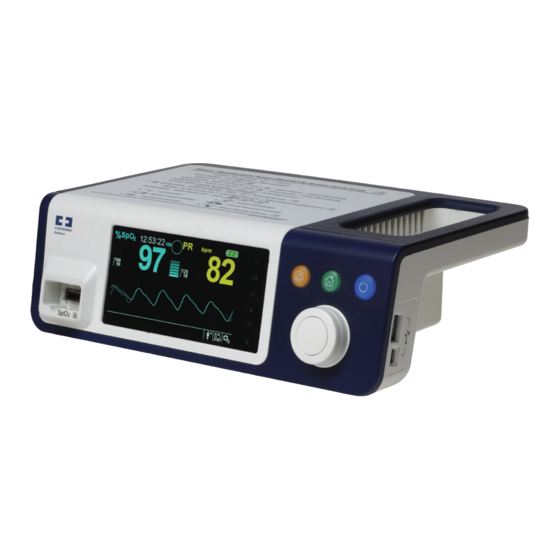
Page 22: Figure 2-2. Display Components
Product Overview Display Figure 2-2. Display Components Upper and lower alarm limits Reflects upper and lower SpO and pulse rate alarm limits. An alarm sounds each time patient saturation or pulse rate values violate these alarm limits. real-time value Indicates hemoglobin oxygen saturation levels. Current upper and lower alarm limit settings appear as smaller values to the left of the dynamic SpO value. - Page 23 Product Views Pulse rate real-time value Displays the pulse rate in beats per minute. Current upper and lower alarm limit settings appear as smaller values to the left of the dynamic pulse rate value. Battery status icon Displays the battery charge remaining on an internal 5- or 10-hour battery.
-
Page 24: Table 2-1. Display Colors
Product Overview Alarm limits menu area Reflects the current audible alarm status. Alarm Audio Paused — Visible in the alarm limits • menu area when the audible alarm is paused for a period of time. Alarm Audio Off — Visible in the alarm limits menu •... -
Page 25: Rear Panel
Product Views Rear Panel 2.4.2 Figure 2-3. Rear Panel Components Equipotential terminal Battery cover Nurse call port AC power connector Operator’s Manual... -
Page 26: Product And Carton Label Symbols
Product Overview Product and Carton Label Symbols 2.4.3 Table 2-2. Symbol Descriptors Symbol Description Symbol Description Type BF Data port Equipotentiality Date of manufacture Prescription only device Keep dry Attention, consult accompanying Fragile documents Atmospheric pressure limitations UL listed Humidity limitations CE Mark Temperature limitations Manufacturer This side up... -
Page 27: Installation
WARNING: Use only Nellcor-approved pulse oximetry sensors and pulse oximetry cables when connecting to the sensor connector. Connecting any other cable or sensor influences the accuracy of sensor data, which may lead to adverse results. -
Page 28: Unpacking And Inspection
Installation WARNING: Use only the Nellcor™ pulse oximetry interface cable with the monitoring system. Use of another interface cable will adversely affect performance. Caution: Follow local government ordinances and recycling instructions regarding disposal or recycling of device components, including its accessories. -
Page 29: Setup
Compact Disc (CD) and/or Operator's Manual Lithium-ion Battery Pack, M-BPL-1 (21) 5 hour AC Power Cord 1. Covidien provides soft copy of monitoring system manuals on a compact disc for easy access and print-on-demand. Order a printed Nellcor™ Bedside SpO Patient Monitoring System Operator’s Manual at no cost or a printed Nellcor™... -
Page 30: Connecting To Power
Installation Connecting to Power 3.4.1 The monitoring system operates on AC power or on a charged internal battery. Prior to connecting to power, perform a safety check of the equipment. Refer- ence Periodic Safety Checks, p. 7-72. To connect the AC power cable: Ensure the AC outlet is properly grounded and supplies the specified voltage and frequency (100-240V~ 50-60 Hz). -
Page 31: Using The Internal Battery
Note: Remove the battery if the monitoring system is not likely to be used for six (6) months. Note: Covidien strongly recommends fully recharging the battery whenever the time between recharges exceeds six (6) months. Note: The monitoring system may not operate if the battery charge is critically low. -
Page 32: Connecting A Nellcor™ Pulse Oximetry Sensor
Use to ensure skin integrity, correct positioning, and adhesion of the sensor. WARNING: Do not use any other cables to extend the length of the Covidien-approved interface cable. Increasing the length will degrade signal quality and may lead to inaccurate measurements. -
Page 33: Figure 3-1. Connecting A Pulse Oximetry Sensor To Interface Cable
9-77, for details regarding sensor selection. To fully connect an Nellcor™ pulse oximetry sensor: Select an appropriate compatible Nellcor™ pulse oximetry sensor for the patient and desired application. When selecting a sensor, consider the patient's weight and activity, adequacy of perfusion, availability of sensor sites, need for sterility, and anticipated dura- tion of monitoring. - Page 34 Installation A Sensor Message occurs when the device cannot obtain an SpO level or a pulse rate. Note: If the sensor is not connected firmly, the monitoring system could lose signal from patient. Note: Physiological conditions, medical procedures, or external agents that may interfere with the monitoring system’s ability to detect and display measurements include dysfunctional hemoglobin, arterial dyes, low perfusion, dark pigment, and externally applied coloring agents, such as nail polish, dye, or pigmented cream.
-
Page 35: Operation
These limits are designed to provide reasonable protection against harmful interference in a typical medical installation. WARNING: For best product performance and measurement accuracy, use only accessories supplied or recommended by Covidien. Use accessories according to their respective Directions for Use. -
Page 36: User Interface
Operation WARNING: Do not use damaged pulse oximetry sensors. Do not use with exposed optical components. Do not immerse completely in water, solvents, or cleaning solutions, since pulse oximetry sensors and connectors are not waterproof. Do not sterilize by irradiation, steam or ethylene oxide. Refer to the cleaning instructions in the Directions for Use for reusable sensors. -
Page 37: Turning Off The Monitoring System
User Interface To power on the monitoring system: Press the Power On/Off Button for more than one (1) second. Ensure the software version, the SpO alarm indicator, and the pulse rate alarm indicator light for approximately two (2) seconds. Figure 4-1. Sample Initial Screen Ensure the POST pass tone sounds when POST completes. -
Page 38: Menu Options Navigation
Operation Menu Options Navigation Navigating menu options on the monitoring system requires manual manipu- lation of the three buttons and the jog dial. Press the desired interface button. Power On/Off button — Press and hold this blue button to power on or to power off the monitoring system. -
Page 39: Menu Structure
Menu Options Navigation Navigation — Rotate the jog dial clockwise or counter-clockwise until a colored highlight surrounds the desired area. Any rotation of the jog dial either navigates or changes the desired option setting. Selection — Press the jog dial to select that desired area, then continue rotating the jog dial until highlighting the desired menu option, then press again. -
Page 40: Quick Access Menus
Operation Table 4-1. Menu structure and available options (Continued) Item Available Selections Default SATSECONDS option SatSeconds™ alarm management setting (Off, 10, 25, 50, 100) PATIENT MODE Menu ADULT option Sets Alarm Limits to standard default thresholds for adult patients Reference PEDIATRIC option Sets Alarm Limits to standard default thresholds for pediatric Table 4-4. ... -
Page 41: Figure 4-4. Quick Access Pr Menu With Alarm Audio Off
Menu Options Navigation PR Menu — Provides access to pulse rate (PR) alarm limit settings and alarm inhi- bition. Reference ALARM/LIMITS Menu, p. 4-35. Figure 4-4. QUICK ACCESS PR Menu with Alarm Audio OFF To select alarm limit settings via Quick Access menus: Rotate the jog dial until the white highlight appears over the SpO or the pulse rate (PR) real-time value field. -
Page 42: Options Menu
Operation Rotate the jog dial to change the field. Exit the menu using either of the listed strategies. Rotate the jog dial to highlight the Return option and press the jog dial. • Press the Return button until the LCD returns to its original screen. •... -
Page 43: Figure 4-6. Volume Selection
Menu Options Navigation Alarm Volume controls the volume (1-8) of alarms. • Key Beep Volume controls the volume (0ff, 1-7) of any button press. • Pulse Volume controls the volume (0ff, 1-7) of the plethysmographic waveform. • Rotate the jog dial to select the desired volume level. Press the jog dial to save the desired volume level. -
Page 44: Figure 4-7. Response Mode Menu
Operation Fast response mode — Responds to changes in blood oxygen saturation • within two (2) to four (4) seconds. This mode can be particularly helpful for situations that require close monitoring. Figure 4-7. Response Mode Menu Note: When in the Fast Response Mode, the monitoring system may produce more SpO and pulse rate alarms than expected. -
Page 45: Alarm/Limits Menu
Menu Options Navigation Figure 4-8. Delete All Trend Data Menu Item At the prompt “Are you sure you want to delete all trend data?” choose one of the following options. Press the jog dial to select NO and keep all trend data. •... - Page 46 Operation WARNING: Do not preset different alarm limits for the same or similar equipment within a single area. Caregivers may choose to adjust SpO and pulse rate (PR) alarm thresholds from default values as necessary. These changes remain in effect until modified again or until a power cycle occurs.
-
Page 47: Patient Mode Menu
Menu Options Navigation Figure 4-9. Alarm/Limits Menu Options Rotate the jog dial to change the desired option value. Reference Menu Structure, p. 4-29, for adult, pediatric, and neonate limit options. Available SpO alarm limit thresholds • Upper and lower SpO alarm limit thresholds –... -
Page 48: Spo 2 Waveform Menu
Operation To set patient mode: Rotate the jog dial to highlight the Patient Mode icon. Press the jog dial to display PATIENT MODE. Figure 4-10. Patient Mode Menu Rotate the jog dial to highlight the desired mode option: Adult, Pediatric or Neo- natal. -
Page 49: Figure 4-11. Highlighting The Waveform Display Area
Menu Options Navigation Figure 4-11. Highlighting the Waveform Display Area Press the jog dial to display the SpO WAVEFORM Menu. Figure 4-12. SpO Waveform Menu Sweep Speed — Access to set the speed at which the SpO waveform trace • moves across the screen. The higher the sweep speed value, the more data appears on the screen. -
Page 50: Managing Alarms And Alarm Limits
Operation Managing Alarms and Alarm Limits WARNING: Do not pause the audible alarm or decrease its volume if patient safety could be compromised. WARNING: Check alarm limits to ensure they are appropriate for each patient being monitored with each use. Ensure alarm limits do not exceed the standard thresholds set by the institution. -
Page 51: Audible Alarm Indicators
Note: If the monitoring system fails to perform as specified, contact Covidien Technical Services, a qualified service technician, or a local supplier for assistance. Audible Alarm Indicators 4.5.1 ... -
Page 52: Table 4-3. Audio Status
Operation Table 4-3. Audio Status Alarm Icon Status Alarm active Alarm audio paused Alarm audio OFF To pause an audible alarm: Press the Alarm Audio Paused button to immediately pause the alarm tone. The alarm resumes after the Alarm Audio Paused period, if the alarm condition remains. -
Page 53: Visual Alarm Indicators
Factory Defaults Visual Alarm Indicators 4.5.2 Visual alarms appear on the screen in order of highest priority, regardless of any audible alarm status. Reference Table 4-2. on page 4-40. Factory Defaults The monitoring system ships with factory default settings. To set different insti- tutional default settings, contact a qualified service technician. -
Page 54: Maintenance Reminder
Schedule regular maintenance and safety checks with a qualified service tech- nician every 24 months. Reference Periodic Safety Checks, p. 7-72. In the case of mechanical or functional damage, contact Covidien or a local Covidien rep- resentative. Reference Obtaining Technical Assistance, p. 1-6. -
Page 55: Data Management
5 Data Management Overview This chapter contains information for accessing patient trend data obtained using the Nellcor™ Bedside SpO Patient Monitoring System. Trend data can be viewed anytime patient trend is stored in the monitoring system. The monitoring system stores up to 96 hours of trend data. When the moni- toring system begins measuring vital signs, it saves data every four (4) seconds. -
Page 56: Graphical Trend Data
Data Management To select Tabular Trend: Rotate the jog dial to highlight the waveform area. Press the jog dial to display the SpO WAVEFORM Menu. Select Tabular Trend. To scroll through Tabular Trend Data: Rotate the jog dial to scroll through the trend data. Clockwise rotation moves forward to newer data. -
Page 57: External Data Communication
External Data Communication Figure 5-2. Graphical Trend Data Screen To scroll through Graphical Trend Data: Rotate the jog dial to highlight Scroll. Press the jog dial to activate scrolling. Rotate the jog dial to scroll through the trend data. Clockwise rotation moves forward to newer data. •... -
Page 58: Nurse Call Interface
Data Management USB interface — Enables firmware upgrades. Reference the Service Manual. • Mini USB interface — Enables trend data downloads and connection to a per- • sonal computer (PC). Nurse Call Interface 5.4.1 WARNING: Do not use the nurse call feature as the primary source of alarm notification. The audible and visual alarms of the monitoring system, used in conjunction with clinical signs and symptoms, are the primary sources for notifying medical personnel that an alarm condition exists. -
Page 59: Trend Data Download
External Data Communication Figure 5-3. Nurse Call Interface Pin Layout Nurse call normally closed Nurse call common lead Nurse call normally open The nurse call feature utilizes a relay closure to signal the nurse station during alarm conditions. Pins 2 and 3 provide a relay that closes during alarm condi- tions. - Page 60 IEC Standard 60950. All combinations of equipment must be in compliance with IEC Standard 60601- 1-1 system requirements. Use either ASCII communication protocol. Nellcor™ ASCII protocol (ASCII 1) • ASCII format compatible with several spreadsheet programs (ASCII 2) •...
-
Page 61: Figure 5-4. Trend Data Download Option
External Data Communication Note: Any trend data download relies on either factory default settings or institutional default settings established by a qualified service technician prior to usage. This includes baud rate and communication protocol selection. To download trend data Power on the monitoring system by pressing the button. -
Page 62: Figure 5-5. Trend Data Download Status
Data Management Press the jog dial again, since the item highlighted is the START option.The status bar indicating total percentage of the download appears and the START option, immediately changes to a CANCEL option. Note: Users may choose to cancel the download operation at any point in the download process by selecting CANCEL and then RETURN. - Page 63 External Data Communication Note: If this is the first time the HyperTerminal program launches, it will prompt the user to set it as the default Telnet program. Depending on institutional requirements, users may choose YES or NO. Click the HYPERTERMINAL option. When the Connect Description window opens, type in the desired file name in the Name field.
-
Page 64: Table 5-1. Operating Status Codes
Data Management different COM port, select the FILE menu, click NEW CONNECTION, and select a different COM port until data values scroll across the HyperTerminal screen. To interpret downloaded trend data: Examine trend data on the HyperTerminal screen, in a spreadsheet, or on a print- out from the personal computer. -
Page 65: Figure 5-6. Sample Trend Data Printout
External Data Communication Figure 5-6. Sample Trend Data Printout Product column headings Data source, firmware version, and system settings Patient data column headings Lists appropriate time and data headings Time column Real-time clock date and time stamp Output Complete Message indicating completion of trend data download Current saturation value %SpO Current pulse rate... - Page 66 Insert the Nellcor™ Bedside SpO Patient Monitoring System compact disc (CD) into the designated personal computer (PC). Copy the COVIDIEN USB to UART Bridge Driver zip file to the PC, installing it in the desired program folder. Right-click on the zipped folder.
-
Page 67: Figure 5-7. Sample Bridge Driver Installer Window
External Data Communication Figure 5-7. Sample Bridge Driver Installer window Reboot the PC for changes to take effect. Connect the monitoring system to the PC, firmly engaging the USB end to the PC and the mini-USB to the monitoring system. Allow the PC to sense the new hardware and load the InstallShield Wizard, which guides users through the entire setup process. - Page 68 Data Management When the InstallShield Wizard provides the end-user license agreement, read it carefully, then click the button for accepting the terms of the license. Click NEXT to formally accept the agreement. Review the Destination Folder mapping. To change the destination, click BROWSE and select the desired mapping.
-
Page 69: Figure 5-9. Sample Device Manager Button Under Hardware Tab
External Data Communication Figure 5-9. Sample DEVICE MANAGER button under hardware tab Select the Ports option from the resulting list. Operator’s Manual... -
Page 70: Figure 5-10. Sample Hardware List In Device Manager Window
Data Management Figure 5-10. Sample Hardware list in Device Manager window Double click the Silicon Labs CP210x USB to UART Bridge option. Note: The listed COM port should match the HyperTerminal COM port designation. Reference To launch HyperTerminal, p. 5-52. Operator’s Manual... -
Page 71: Figure 5-11. Sample Initial Usb To Uart Bridge Properties Window
External Data Communication Figure 5-11. Sample Initial USB to UART Bridge Properties Window Click the Port Settings tab. Set the bits per second to one of four possible baud rates: 19200, 38400, 57600, or 115200. The factory default is 19200 bps. Operator’s Manual... -
Page 72: Firmware Upgrades
Data Management Figure 5-12. Sample Baud rate list under Port Settings tab Click the OK button to complete the process. Reference To download trend data, p. 5-51, and proceed to step 8, utilizing HyperTerminal to connect to the monitoring system. Firmware Upgrades 5.4.3 Contact a qualified service technician to perform any firmware upgrade to the monitoring system, as described in the Service Manual. -
Page 73: Overview
6 Performance Considerations Overview This chapter contains information about optimizing the performance of the Nellcor™ Bedside SpO Patient Monitoring System. Verify the performance of the monitoring system by following the procedures outlined in the Service Manual. Have a qualified service technician perform these procedures prior to initial installation in a clinical setting. -
Page 74: Performance Considerations
Performance Considerations Performance Considerations Overview 6.3.1 This section contains information for optimizing the performance of the moni- toring system. Verify the performance of the monitoring system by following the procedures outlined in the SRC-MAX Pulse Oximetry Functional Tester Technical Manual. Have a qualified service technician perform these procedures prior to initial installation in a clinical setting and every 24 months as part of preventive main- tenance. -
Page 75: Sensor Performance Considerations
Failure to cover the pulse oximetry sensor site with opaque material in high ambient light conditions may result in inaccurate measurements. Inaccurate Sensor Measurement Conditions A variety of conditions can cause inaccurate Nellcor™ pulse oximetry sensor measurements. Incorrect application of the pulse oximetry sensor •... - Page 76 • Recommended Usage Select an appropriate Nellcor™ pulse oximetry sensor, apply it as directed, and observe all warnings and cautions presented in the Directions for Use accom- panying the sensor. Clean and remove any substances such as nail polish from the application site.
-
Page 77: Reducing Emi (Electromagnetic Interference)
Performance Considerations Reducing EMI (Electromagnetic Interference) 6.3.4 WARNING: Keep patients under close surveillance when monitoring. It is possible, although unlikely, that radiated electromagnetic signals from sources external to the patient and the monitoring system can cause inaccurate measurement readings. ... -
Page 78: Obtaining Technical Assistance
Performance Considerations Turn equipment in the vicinity off and on to isolate the offending equipment. • Reorient or relocate the interfering equipment. • Increase the separation between the interfering equipment and the monitoring • system. Connect the equipment into an outlet on a circuit different from that to which the •... -
Page 79: Preventive Maintenance
For sensors, follow cleaning instructions in the directions for use shipped with those components. Before attempting to clean a Nellcor™ pulse oximetry sensor, read the Directions for Use enclosed with the sensor. Each sensor model has cleaning instructions specific to that sensor. -
Page 80: Recycling And Disposal
Explosion hazard — Do not connect the battery reversed in positive (+) and negative (-) terminals. Do not charge the battery with polarities reversed. Caution: Covidien strongly recommends recharging the battery when it has not been recharged for six (6) or more months. Caution: Follow local government ordinances and recycling instructions regarding disposal or recycling of device components, including batteries. - Page 81 Battery Maintenance Caution: Do not use any chargers not specified by Covidien. Caution: Do not mistreat the battery, or use the battery in applications not recommended by Covidien. Caution: Keep the battery out of reach of children to avoid any accidents.
-
Page 82: Periodic Safety Checks
24 months. Inspect the equipment for mechanical and functional damage or deterioration. • Inspect the safety relevant labels for legibility. Contact Covidien or a local Covidien • representative, if labels are damaged or illegible. Ensure all user interface keys, cables, and accessories function normally. -
Page 83: Troubleshooting
8 Troubleshooting Overview This chapter describes how to troubleshoot common problems while using the Nellcor™ Bedside SpO Patient Monitoring System. General WARNING: Check the patient's vital signs by alternate means should there be any doubt about the accuracy of any measurement. Request a qualified service technician confirm the monitoring system is functioning correctly. -
Page 84: Error Conditions
Cable/Sensor Disconnect Warm site Cover sensor Loss of Pulse Use forehead, nasal, or ear sensor (adult patient only) Use Nellcor™ adhesive sensor Secure cable Secure with headband (MAX-FAST) Remove nail polish Loosen sensor (too tight) Isolate external interference (electrosurgical device, cell phone) - Page 85 Screen does not function prop- Do not use the monitoring system; contact a qualified service technician or erly and the power-on beep Covidien Technical Services. tones do not sound No sound generation Verify setting point of volume is not 0 or 1.
-
Page 86: Return
Managing Alarms and Alarm Limits, p. 4-40, for any issues related to alarm conditions. Return Contact Covidien or a local Covidien representative for shipping instructions, including a Returned Goods Authorization (RGA) number. Reference Obtain- ing Technical Assistance, p. 1-6. Unless otherwise instructed by Covidien, it is not necessary to return the sensor or other accessory items with the monitor- ing system. -
Page 87: Accessories
WARNING: Use only Nellcor-approved pulse oximetry sensors and pulse oximetry cables when connecting to the sensor connector. Connecting any other cable or sensor influences the accuracy of the sensor data, which may lead to adverse results. -
Page 88: Table 9-1. Nellcor™ Pulse Oximetry Sensor Models And Patient Sizes
Use the following table for selection or contact Covidien or a local Covidien representative. Reference Sensor Performance Considerations, p. 6- 65. Use the Nellcor™ pulse oximetry interface cable to connect the pulse oxim- etry sensor to the monitoring system. Table 9-1. Nellcor™ Pulse Oximetry Sensor Models and Patient Sizes Nellcor™ Pulse Oximetry Sensor... -
Page 89: Optional Equipment
Optional Equipment Table 9-1. Nellcor™ Pulse Oximetry Sensor Models and Patient Sizes (Continued) Nellcor™ Pulse Oximetry Sensor Patient Size MAX-R >50 kg Nellcor™ Adult SpO Nasal Sensor (Sterile, single-use only) MAX-FAST >10 kg Nellcor™ Forehead SpO Sensor DS-100A >40 kg Nellcor™ Adult SpO... -
Page 90: Biocompatibility Testing
Covidien representative www.covidien.com Biocompatibility Testing Biocompatibility testing has been conducted on Nellcor™ pulse oximetry sensors in compliance with ISO 10993-1, Biological Evaluation of Medical Devices, Part 1: Evaluation and Testing. The pulse oximetry sensors have passed the recommended biocompatibility testing and are therefore in compli- ance with ISO 10993-1. -
Page 91: 10 Theory Of Operations
10.2 The monitoring system uses pulse oximetry to measure functional oxygen sat- uration in the blood. Pulse oximetry works by applying a Nellcor™ pulse oxim- etry sensor to a pulsating arteriolar vascular bed, such as a finger or toe. The sensor contains a dual light source and a photodetector. -
Page 92: Automatic Calibration
10.4 Some models of commercially available bench top functional testers and patient simulators can be used to verify the proper functionality of Covidien Nellcor™ monitoring systems, sensors, and cables. Reference the individual testing device's operator's manual for the procedures specific to the model of tester used. -
Page 93: Unique Technologies
Unique Technologies These capabilities are beyond the scope of known bench top testers. SpO measurement accuracy can only be evaluated in vivo by comparing monitoring system readings with values traceable to SaO2 measurements obtained from simultaneously sampled arterial blood using a laboratory CO-oximeter. Many functional testers and patient simulators have been designed to inter- face with the monitoring system's expected calibration curves and may be suit- able for use with monitoring systems and/or sensors. -
Page 94: Measured Versus Calculated Saturation
Theory of Operations Measured versus Calculated Saturation 10.5.2 When calculating saturation from a blood gas partial pressure of oxygen (PO2), the calculated value may differ from the SpO measurement of a monitoring system. This usually occurs when saturation calculations exclude corrections for the effects of variables such as pH, temperature, the partial pressure of carbon dioxide (PCO2), and 2,3-DPG, that shift the relationship between PO2 and SpO... -
Page 95: Satseconds™ Alarm Management Feature
SatSeconds™ Alarm Management Feature results in an increase in the dynamic averaging. If the resulting dynamic averaging time exceeds 20 seconds for SpO , the algorithm sets the pulse search bit while continuing to update SpO and pulse rate values every second. As such measurement conditions extend, the amount of data required may continue to increase. -
Page 96: First Spo Event
Theory of Operations First SpO Event 10.6.1 Consider the first event. Suppose the SatSeconds alarm limit is set to 25. The patient’s SpO drops to 79% and the duration of the event is two (2) seconds before saturation again exceeds the lower alarm threshold of 85%. 6% drop below the lower alarm limit threshold x 2 second duration below the lower threshold 12 SatSeconds;... -
Page 97: Second Spo Event
SatSeconds™ Alarm Management Feature Second SpO Event 10.6.2 Consider the second event. Suppose the SatSeconds alarm limit is still set to 25. The patient’s SpO drops to 84% and the duration of the event is 15 seconds before saturation again exceeds the lower alarm threshold of 85%. 1% drop below the lower alarm limit threshold x15 second duration below the lower threshold 15 SatSeconds;... -
Page 98: Third Spo Event
Theory of Operations Third SpO Event 10.6.3 Consider the third event. Suppose the SatSeconds alarm limit is still set to 25. During this event, the patient’s SpO drops to 75%, which is 10% below the lower alarm threshold of 85%. Since the patient’s saturation does not return to a value over the lower alarm threshold within 2.5 seconds, an alarm sounds. -
Page 99: The Satseconds Safety Net
SatSeconds™ Alarm Management Feature The SatSeconds Safety Net 10.6.4 The SatSeconds “Safety Net” is for patients with saturation levels frequently below the limit, but not staying below the limit long enough for the SatSec- onds time setting to be reached. When three or more limit violations occur within 60 seconds, an alarm sounds even if the SatSeconds time setting has not been reached. - Page 100 Theory of Operations Page Left Intentionally Blank Operator’s Manual...
-
Page 101: 11 Product Specifications
11 Product Specifications Overview 11.1 This chapter contains physical and operational specifications of the Nellcor™ Bedside SpO Patient Monitoring System. Ensure all product require- ments are met prior to installation of the monitoring system. Physical Characteristics 11.2 Enclosure Weight 1.6 kg (3.5 lbs.) including battery Dimensions 255 ×... -
Page 102: Electrical
Product Specifications Electrical 11.3 Battery power requirement AC 100-240VAC, 50/60Hz, 45 VA 10.8 V/ 2200 mAh Voltage and capacity of Li-Ion, 5 hour 10.8 V/4400 mAh Voltage and capacity of Li-Ion, 10hour Compliance 91/157/EEC Fast-acting fuse 2A 32VAC,/DC Fast-acting fuse 500 mA 32VAC/50DC 1. -
Page 103: Tone Definition
Tone Definition Tone Definition 11.5 Table 11-2. Tone Definitions Tone Category Description High Priority Alarm Tone Volume level Adjustable (level 1-8) Pitch (± 20Hz) 976 Hz Pulse width (± 20msec) 150 msec (IEC60601-1-8) Number of pulses in burst 10, interburst interval of 4 sec (IEC60601-1-8) Repetitions Continually Medium Priority Alarm Tone... -
Page 104: Performance Specifications
Product Specifications Table 11-2. Tone Definitions (Continued) Tone Category Description Key Beep Volume level Adjustable (Off, level 1-7), (Invalid key presses are ignored) Pitch (± 20Hz) 440 Hz (valid), 168 Hz (invalid) Pulse width (± 20msec) 110 msec Number of pulses Repetitions No repeat POST Pass Tone Volume level... -
Page 105: Sound Pressure
(ARMS) range. Reference the Clinical Studies section for test results. For a complete listing of SpO2 accuracy across the full line of available Nellcor™ sensors, contact Covidien, a local Covidien representative, or locate it online at www.covidien.com. -
Page 106: Product Compliance
Caution: For best product performance and measurement accuracy, use only accessories supplied or recommended by Covidien. Use accessories according to the Directions for Use. Use only accessories that have passed the recommended biocompatibility testing in compliance with ISO10993-1. The use of accessories, sensors, and cables other than those specified may result in inaccurate readings of the monitoring system and increased emission and/or decreased electromagnetic immunity of the monitoring system. -
Page 107: Table 11-6. Electromagnetic Emissions Guidelines
Manufacturer’s Declaration The monitoring system is suitable for prescription use only in the electromag- netic environments specified in the standard. Use the monitoring system in accordance with the electromagnetic environments described. Electromagnetic Emissions Table 11-6. Electromagnetic Emissions Guidelines Emissions Test Compliance Electromagnetic Environment Guidance RF emissions Group 1, The oximeter is suitable for use in all establishments. -
Page 108: Table 11-7. Electromagnetic Immunity Guidelines
Product Specifications Electromagnetic Immunity Note: These guidelines may not apply in all situations. Electromagnetic propagation is affected by absorption and reflection from structures, objects, and people. Table 11-7. Electromagnetic Immunity Guidelines Immunity IEC/EN 60601-1-2 Compliance Electromagnetic Environment Test Test Level Level Guidance Electrostatic ±... -
Page 109: Table 11-8. Recommended Separation Distances
Manufacturer’s Declaration Table 11-8. Recommended Separation Distances Immunity IEC/EN 60601-1-2 Compliance Electromagnetic Environ- Test Test Level Level ment Guidance Frequency of Equation for Separation Transmitter Distance (d) Conducted RF 3 Vrms 3 Vrms 1.2 P 150 kHz 150 kHz IEC/EN 61000-4-6 80 MHz 80 MHz 150 kHz to 80 MHz Radiated RF... -
Page 110: Sensor And Cable Compliance
Product Specifications Sensor and Cable Compliance 11.9.2 WARNING: The use of accessories, sensors, and cables other than those specified may result in inaccurate readings of the monitoring system and increased emission of the monitoring system. Table 11-9. Cables and Sensors Item Maximum Length Sensors Pulse oximetry sensor cable... -
Page 111: Table 11-10. Earth And Enclosure Leakage Current Specifications
Manufacturer’s Declaration Table 11-10. Earth and Enclosure Leakage Current Specifications Earth Leakage Current IEC 60601-1 Neutral ANSI/AAMI Condition AC Line Polarity Line Cord Line Cord IEC 60601-1 ES 60601-1: 2005 Normal Normal Closed Closed 500 µA 300 µA Single Fault Open Closed 1000 µA Closed Open... -
Page 112: Table 11-11. Patient Applied And Patient Isolation Risk Current
Product Specifications Table 11-11. Patient Applied and Patient Isolation Risk Current Patient Applied Risk Current IEC 60601-1 Power Line ANSI/AAMI Condition AC Line Polarity Neutral Line Ground Cable ES 60601-1: 2005 Normal Normal Closed Closed 100 µA Single Fault Open Closed 500 µA Closed Open Normal... -
Page 113: Overview
Patient Monitoring System. One (1) prospective, controlled hypoxia clinical study was conducted to demon- strate the accuracy of Nellcor™ sensors when used in conjunction with the Nellcor™ Bedside Respiratory Patient Monitoring System. The study was per- formed with healthy volunteers at a single clinical laboratory. Accuracy was estab- lished by comparison to CO-oximetry. -
Page 114: Clinical Studies
108-250 Very light Olive Skin pigment Dark olive/Medium black Extremely dark/Blue black Study Results Accuracy was calculated using the root mean square difference (RMSD). Table A-2. SpO Accuracy for Nellcor™ Sensors vs. CO-oximeters MAX-A MAX-N MAX-FAST Decade Data Arms Data Arms Data... -
Page 115: Adverse Events Or Deviations
Adverse Events or Deviations Figure A-1. Modified Bland-Altman Plot Test Sensor; Avg CO-oximeter value 70-100% SpO Avg CO-oximeter value 70-100% SpO Oximetry board with MAX-A sensor Trendline of MAX-A sensor Oximetry board with MAX-N sensor Trendline of MAX-N sensor Oximetry board with MAX-FAST sensor Trendline of MAX-FAST sensor Adverse Events or Deviations The study was conducted as expected with no adverse events and no devia-... -
Page 116: Conclusion
Clinical Studies Conclusion The pooled results indicate that for a saturation range of 60-80% for SpO , the acceptance criterion was met for the monitoring system when tested with MAX-A, MAX-N and MAX-FAST sensors. The pooled results indicate that for a saturation range of 70-1 00% for SpO , the acceptance criterion was met. - Page 117 Related documents ........6 Caution Warranty ........... 7 Accessory equipment ........ 4 Accuracy ............ 5 Battery disposal ........72 Nellcor™ pulse oximetry sensor Conductor integrity ........5 Connection ..........22 Equipment inspection ......5 Disinfection ..........69 Excessive environmental conditions ..4 Performance considerations ....
- Page 118 Service, Returning your Oximeter .....76 Specifications Electrical ..........95 Physical ..........91, 103 Storage Altitude ............92 Relative humidity ........92 Temperature ..........92 Symbols Atmospheric pressure ......16 Attention ..........16 CE mark ............16 Data port ..........16 Date of manufacture ......16 Equipotentiality ........16 EU representative ........16 Fragile ............16 Humidity limitations .......16 Keep dry ..........16...
- Page 120 Part No. 10006048 Rev B (A7213-1) 07/2012 © 2012 Covidien. Covidien llc 15 Hampshire Street, Mansfield, MA 02048 USA. Covidien Ireland Limited, IDA Business & Technology Park, Tullamore. www.covidien.com [T] 1.800.NELLCOR...
Need help?
Do you have a question about the Nellcor and is the answer not in the manual?
Questions and answers