Sign In
Upload
Download
Table of Contents
Contents
Add to my manuals
Delete from my manuals
Share
URL of this page:
HTML Link:
Bookmark this page
Add
Manual will be automatically added to "My Manuals"
Print this page
×
Bookmark added
×
Added to my manuals
Manuals
Brands
Covidien Manuals
Medical Equipment
Nellcor GR101704
Service manual
Covidien Nellcor GR101704 Service Manual
Bedside respiratory patient monitoring system
Hide thumbs
1
2
Table Of Contents
3
4
5
6
7
8
9
10
11
12
13
14
15
16
17
18
19
20
21
22
23
24
25
26
27
28
29
30
31
32
33
34
35
36
37
38
39
40
41
42
43
44
45
46
47
48
49
50
51
52
53
54
55
56
57
58
59
60
61
62
63
64
65
66
67
68
69
70
71
72
73
74
75
76
77
78
79
80
81
82
83
84
85
86
87
88
89
90
91
92
93
94
95
96
97
98
99
100
101
102
103
104
105
106
107
108
109
110
111
112
113
114
115
116
117
118
119
120
121
122
123
124
125
126
127
128
129
130
131
132
133
134
135
136
137
138
139
140
141
142
143
144
145
146
147
148
149
150
151
152
153
154
155
156
157
158
159
160
161
162
163
164
165
166
167
168
169
170
171
172
173
174
175
176
177
178
179
180
181
182
183
184
185
186
187
188
189
190
191
192
193
194
195
196
197
198
199
200
201
202
203
204
205
206
207
208
209
210
211
212
213
214
215
216
217
218
219
220
221
222
223
224
225
226
227
228
229
230
231
232
233
234
235
236
page
of
236
Go
/
236
Contents
Table of Contents
Troubleshooting
Bookmarks
Table of Contents
Table of Contents
1 Introduction
Overview
Intended Audience
Safety Information
Safety Symbols
Warnings
Table 1-1. Safety Symbol Definitions
Cautions
Obtaining Technical Assistance
Technical Services
On-Screen Help
Related Documents
Warranty Information
2 Product Specifications
Overview
Physical Characteristics
Electrical Requirements
Power
Battery
Rating of Nurse Call Relay
Environmental Conditions
Operating
Transport and Storage
Sensor Accuracy and Ranges
Table 2-1. Nellcor™ Sensor Accuracy and Ranges
Sound Pressure
Product Compliance
Table 2-2. Nellcor™ Sensor Operating Range and Power Dissipation
Table 2-3. Sound Pressure in Decibels
Manufacturer's Declaration and Guidance
Electromagnetic Compatibility (EMC)
Table 2-4. Frequency Band, Output Power, and Modulation Type
Table 2-5. Electromagnetic Emissions Guidelines and Compliance
Electromagnetic Emissions
Table 2-6. Electromagnetic Immunity Guidelines and Compliance
Table 2-7. Recommended Separation Distance Calculations
Table 2-8. Recommended Separation Distances
Table 2-9. Sensor and Cable Length
Ground Integrity
Safety Tests
Table 2-10. Earth and Enclosure Leakage Current Specifications
Table 2-11. Patient Applied and Patient Isolation Risk Current
3 Theory of Operations
Overview
Block Diagram
Figure 3-1. Block Diagram
Theoretical Principles
Automatic Calibration
Functional Testers and Patient Simulators
Unique Technologies
Functional Versus Fractional Saturation
Measured Versus Calculated Saturation
Data Update Period, Data Averaging, and Signal Processing
Figure 3-2. Oxyhemoglobin Dissociation Curve
System Features
Nellcor™ Sensor Technology
Satseconds™ Alarm Management Parameter
Figure 3-4. First Spo 2 Event: no Satseconds Alarm
Figure 3-5. Second Spo 2 Event: no Satseconds Alarm
Oximax SPD™ Alert Parameter
Figure 3-7. Clinically Significant Desaturation Patterns
Pulse Rate Delay Alarm Management Parameter
4 Product Overview
Overview
Product Description
Indications for Use
List of Components
Synopsis
Table 4-1. Typical Packing List
Product Views
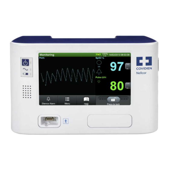
Front Panel
Figure 4-1. Front Panel
Monitoring Screen
Figure 4-2. Sample Monitoring Screen Elements
Rear Panel
Labeling Symbology
Table 4-2. Labeling Symbols and Descriptions
5 Installation
Overview
Safety Reminders
Product Setup
Mounting Options and Transport Considerations
Connection to an AC Power Source
Battery Insertion
Battery Charge
Battery Power Usage
Connection to Nellcor™ Sensors
Figure 5-1. Sensor Cable Insertion into Interface Cable
6 Operation
Overview
Power
AC Power
Battery Power
Table 6-1. Battery Power Status
Power up
System Resets
Automatic Shutdown and Power off
Figure 6-1. Sample POST Splash Screen
Nellcor™ Sensor Usage
Sensor Detection
Sensor Detection Failure
Figure 6-2. Sensor Type Message
User Interface
Default Monitoring Screen and Trend Data
Status Messages and Alarms in the Monitoring Status Field
Figure 6-3. Default Monitoring Screen Layout
Alarm Management and Status Messages
Figure 6-4. Sample User Prompt Message: READY
Figure 6-5. Sample Status Message: MONITORING
Figure 6-6. High Priority Alarm: BATTERY CRITICALLY LOW
Figure 6-7. Medium Priority Alarm: Spo 2 LOW
Figure 6-8. Low Priority Alarm: SENSOR off
Audible Alarm Management
Figure 6-9. Sample Alarm Limit Violations
Visual Alarm Management
HELP Option
Service Mode
Table 6-2. Possible User Interface Settings
Table 6-3. Possible Alarm Management Settings
Table 6-4. Possible Data Interface Settings
Table 6-5. Possible Service Functions
Figure 6-10. Prompt to Enter SERVICE MODE
Settings Menu
Alarm Limits
Alarm System
Display Settings
Figure 6-11. Default Monitoring Screen Layout
Logs Menu
Service Menu
Covidien Service Menu
About Monitor Menu
Parameter Activation Menu
7 Trend Data Access
Overview
Trend Data Management
Trend Data Basics
Data Port Connectivity
Overview
Table 7-1. Input and Output Configuration Options
Typical Equipment Used for Connectivity
Data Port Configuration Information
Table 7-2. Sample Equipment Types
Table 7-3. DB-15 Signal Pinouts
Figure 7-1. DB-15 Pin Layout
Table 7-4. RJ-45 Signal Pinouts
Figure 7-2. RJ-45 Receptacle
Figure 7-3. RJ-45 Pin Layout
Table 7-5. USB Signal Pinouts
Figure 7-4. USB Pin Layout
Table 7-6. Network Configuration Icons
Figure 7-5. New Network Connection Windows
Figure 7-6. New Network Connection Windows
Data Port Communications
Using the Nurse Call Interface
Nurse Call Feature
Table 7-7. Nurse Call Relay Pin States
Setting Nurse Call RS-232 Polarity
Figure 7-7. Nurse Call Polarity Screen
Calculating the Analog Voltage Output
Table 7-8. Analog Pinouts
8 Performance Considerations
Overview
Oximetry Considerations
Monitoring System Constraints
Nellcor™ Sensor Performance Considerations
Patient Conditions
Reducing EMI (Electromagnetic Interference)
9 Product Maintenance
Overview
Cleaning
Periodic Safety Checks
Service and Upgrades
Storage
Monitoring System Transport and Storage
Removed Battery Storage
10 Modification and Testing
Overview
Table 10-1. Possible User Interface Settings
Table 10-2. Possible Alarm Management Settings
Table 10-3. Possible Data Interface and Service Settings
Setting Institutional Defaults
Figure 10-1. Prompt to Enter SERVICE MODE
Performance Verification
Overview
Required Equipment
Table 10-4. Equipment and Descriptions
Safety Testing Standards
Battery Check
Battery Power
Battery Charge
Performance Tests
Power-On Defaults and Alarm Ranges
Operational Setup
Figure 10-2. Sample: Configuring Alarms
Figure 10-3. Sample: Configuring Alarms with Silenced Alarm
Overall Performance Check
Pulse Oximetry Functional Tests
Figure 10-4. Sensor Identification
Figure 10-5. SRC-MAX Functional Tester
Table 10-5. Functional Tests Options
Figure 10-10. MOD Test: BPM 60, Spo 2 75, and MOD Low
Figure 10-11. MOD Test: BPM 60, Spo 2 75, and MOD High
Figure 10-12. MOD Test: BPM 200, Spo 2 75, and MOD High
Figure 10-13. MOD Test: BPM 60, Spo 2 90, and MOD High
Figure 10-14. LIGHT Test: BPM 60, Spo 2 75, MOD Low, Light Low
Figure 10-15. LIGHT Test: BPM 60, Spo 2 75, MOD Low, Light High
Figure 10-16. LIGHT Test: BPM 200, Spo 2 75, MOD Low, Light High
Figure 10-17. LIGHT Test: BPM 60, Spo 2 90, MOD Low, Light High
Figure 10-18. LIGHT Test: BPM 60, Spo 2 90, MOD High, Light High
Setting Nurse Call
Test Data Sheet Form
Table 10-6. Performance and Functional Tests
Table 10-7. Electrical Safety Tests
Monitoring Screen Calibration
Figure 10-19. Initial Calibration Screen
Software and Firmware Upgrades
11 Troubleshooting
Overview
System Condition Categories
Figure 11-1. Ready Prompt
Figure 11-2. Sensor Disconnected Message and Help Screen
Figure 11-3. Stacked Alarm/Alerts
User Prompts and Messages
Alarms and Error Conditions
Alarms
Table 11-1. Common User Prompts and Messages
Table 11-2. Initial Alarm Priority for Errors
Figure 11-4. Sample Speaker Failure Message
Correctable Error Conditions
Table 11-3. Common Correctable Problems and Resolutions
Power Failure Issues
Table 11-4. Power Failure Issues
Monitoring Screen Issues
Alarm Issues
Communication Issues
Table 11-7. Common Prompts and Error Messages
Operational Performance Issues
Hardware Issues
Table 11-8. Common Operational Performance Issues
Table 11-9. Common Prompts and Error Messages
System Errors and Software Issues
Non-Correctable Failures
Figure 11-5. System Error
Product Return
12 Repair
Overview
Spare Parts List
Table 12-1. Available Spare Parts
Figure 12-1. Exploded View of Removable Components
Figure 12-2. Exploded View of Internal Components
Repair Prerequisites and Required Equipment
Basic Preventive Maintenance
Table 12-2. Required Equipment
Battery or Battery Access Door Replacement
Figure 12-3. External Fuse Removal
Fuse Removal and Replacement
Figure 12-4. Battery Removal
Rubber Feet Replacement
Figure 12-5. Rubber Feet Replacement
Chassis Disassembly and Reassembly
Parameter Module Replacement
Figure 12-6. Parameter Module Screw Removal
Figure 12-7. Parameter Module Tab Release
Figure 12-8. Parameter Module Assembly Removal
Figure 12-9. Parameter Module Disassembly
Figure 12-10. Parameter Board PCB and Oximetry Module Removal
Monitoring System Chassis Disassembly
Figure 12-11. Corner Chassis Screws Removal
Table 12-3. Main PCB Connections
Monitoring System Chassis Reassembly
Figure 12-12. Initial Chassis Disassembly
Power Components Replacement
Power Entry Module (PEM) Replacement
Right Power Cable Assembly Replacement
Figure 12-13. Right Power Cable Assembly Replacement
Battery Components Replacement
Figure 12-14. Battery Cradle Removal
Figure 12-15. Power Supply PCB Removal
Figure 12-16. Battery Interconnect PCB Removal
Figure 12-17. Cooling Fan Removal
Left Power Cable Assembly Replacement
Figure 12-18. Left Power Cable Assembly Replacement
Front Panel Components Replacement
Main PCB Components Replacement
Table 12-4. Main PCB Connections
Figure 12-19. Main PCB Connectors
Figure 12-20. Antennae PCB and UFL Connectors Removal
Figure 12-21. Single Board Computer (SBC) Removal
LCD Assembly with Overlay Replacement
Figure 12-22. LCD Assembly Removal
Return Authorization and Shipment
General Instructions for Return
Repackage in Original Carton
Figure 12-23. Components to Repackage in Original Carton
Repackage in an Alternate Carton
Index
Advertisement
Quick Links
1
Service Mode
Download this manual
Service Manual
Nellcor™
Bedside Respiratory Patient Monitoring System
Table of
Contents
Previous
Page
Next
Page
1
2
3
4
5
Advertisement
Table of Contents
Need help?
Do you have a question about the Nellcor GR101704 and is the answer not in the manual?
Ask a question
Questions and answers
Related Manuals for Covidien Nellcor GR101704
Medical Equipment Covidien Nellcor GR101704-RR Operator's Manual
Bedside respiratory patient monitoring system respiration rate version 2.0 (38 pages)
Medical Equipment Covidien Nellcor FLEXMAX Instructions For Use Manual
Flexible spo 2 sensor, reusable (196 pages)
Medical Equipment Covidien Nellcor Operator's Manual
Portable spo2 patient monitoring system (112 pages)
Medical Equipment Covidien Nellcor Operator's Manual
Bedside spo2 patient monitoring system (120 pages)
Medical Equipment Covidien Nellcor OxiMax N-600x Operator's Manual
(208 pages)
Medical Equipment Covidien Nellcor Series Operator's Manual Addendum
Bedside respiratory patient monitoring system, respiration rate version 1.0 (36 pages)
Medical Equipment Covidien Nellcor OxiMax N-600x Operator's Manual
Alarm management system (146 pages)
Medical Equipment Covidien Nellcor PM100N Home Use Manual
Bedside spo2 patient monitoring system (48 pages)
Medical Equipment Covidien Nellcor PM10N Service Manual
Portable spo2 patient monitoring system (112 pages)
Medical Equipment Covidien Nellcor PM10N Home Use Manual
Portable spo2 patient monitoring system (50 pages)
Medical Equipment Covidien Nellcor D-YSPD Instructions For Use Manual
Pediatric spo2 sensor clip reusable (6 pages)
Medical Equipment Covidien Newport e360 Service Manual
Ventilator with accessories (154 pages)
Medical Equipment Covidien INVOS 5100C Operator's Manual
Regional saturation patient monitoring system (178 pages)
Medical Equipment Covidien Kendall SCD 700 Series Operation And Service Manual
Sequential compression system (771 pages)
Medical Equipment Covidien Valleylab FX8 Series Quick Reference Manual
Energy platform (2 pages)
Medical Equipment Covidien Force FX Service Manual
Electrosurgical generator c (246 pages)
This manual is also suitable for:
Nellcor pm1000n
Nellcor gr101704-rr
Nellcor pm1000n-rr
Table of Contents
Save PDF
Print
Rename the bookmark
Delete bookmark?
Delete from my manuals?
Login
Sign In
OR
Sign in with Facebook
Sign in with Google
Upload manual
Upload from disk
Upload from URL


Need help?
Do you have a question about the Nellcor GR101704 and is the answer not in the manual?
Questions and answers