Danfoss VLT AutomationDrive FC 300 Design Manual
90-1200 kw
Hide thumbs
Also See for VLT AutomationDrive FC 300:
- Design manual (296 pages) ,
- Programming manual (277 pages) ,
- Operating instructions manual (169 pages)

Related Manuals for Danfoss VLT AutomationDrive FC 300


Summary of Contents for Danfoss VLT AutomationDrive FC 300
- Page 1 MAKING MODERN LIVING POSSIBLE Design Guide ® AutomationDrive FC 300 90-1200 kW www.danfoss.com/drives...
-
Page 3: Table Of Contents
® Contents AutomationDrive FC 300 Design Guide 90-1200 kW Contents 1 How to Read this Design Guide 1.1 How to Read This Design Guide - FC 300 1.2 Available Literature 1.3 Approvals 1.4 Symbols 1.5 Abbreviations 1.6 Definitions 1.7 Power Factor 2 Safety and Conformity 2.1 Safety Precautions 2.2 Caution... - Page 4 ® Contents AutomationDrive FC 300 Design Guide 90-1200 kW 3.4.9 Process PID Control Programming Order 3.4.10 Optimisation of the Process Regulator 3.4.11 Ziegler Nichols Tuning Method 3.5 General Aspects of EMC 3.5.1 General Aspects of EMC Emissions 3.5.2 EMC Test Results 3.5.3 Emission Requirements 3.5.4 Immunity Requirements 3.6 Galvanic Isolation (PELV)
- Page 5 ® Contents AutomationDrive FC 300 Design Guide 90-1200 kW 5.2 Ordering Numbers 5.2.1 Options and Accessories 5.2.2 Brake Resistors 5.2.3 Advanced Harmonic Filters 5.2.4 Sine-Wave Filter Modules, 380-690 V AC 5.2.5 dU/dt Filters 6 Mechanical Installation 6.1 Pre-installation 6.1.1 Receiving the Frequency Converter 6.1.2 Transportation and Unpacking 6.1.3 Lifting 6.1.4 Mechanical Dimensions...
- Page 6 ® Contents AutomationDrive FC 300 Design Guide 90-1200 kW 7.2.4 Power/Semiconductor Fuse Size 7.2.5 Power/Semiconductor Fuse Options 7.2.6 Supplementary Fuses 7.2.7 High Power Fuses 12-Pulse 7.2.8 Supplementary Fuses - High Power 7.3 Disconnectors and Contactors 7.3.1 Mains Disconnects - Frame Sizes E and F 7.3.2 Mains Disconnects, 12-Pulse 7.3.3 Mains Contactors 7.4 Additional Motor Information...
- Page 7 ® Contents AutomationDrive FC 300 Design Guide 90-1200 kW 7.8.4 RFI Switch 7.9 Mains Supply Interference/Harmonics 7.9.1 The Effect of Harmonics in a Power Distribution System 7.9.2 Harmonic Limitation Standards and Requirements 7.9.3 Harmonic Mitigation 7.9.4 Harmonic Calculation 7.10 Residual Current Device 7.11 Final Setup and Test 8 Application Examples 8.1 Automatic Motor Adaptation (AMA)
- Page 8 ® Contents AutomationDrive FC 300 Design Guide 90-1200 kW 9.8 MCB 113 Extended Relay Card 9.9 Brake Resistors 9.10 LCP Panel Mounting Kit 9.11 Sine-wave Filters 9.12 High Power Options 9.12.1 Frame Size D Options 9.12.1.1 Load Share Terminals 9.12.1.2 Regeneration Terminals 9.12.1.3 Anti-Condensation Heater 9.12.1.4 Brake Chopper 9.12.1.5 Mains Shield...
- Page 9 ® Contents AutomationDrive FC 300 Design Guide 90-1200 kW 10.8 Examples 10.8.1 Writing a Parameter Value 10.8.2 Reading a Parameter Value 10.9 Modbus RTU Overview 10.9.1 Assumptions 10.9.2 Prerequisite Knowledge 10.9.3 Modbus RTU Overview 10.9.4 Frequency Converter with Modbus RTU 10.10 Network Configuration 10.10.1 Frequency Converter with Modbus RTU 10.11 Modbus RTU Message Framing Structure...
-
Page 10: How To Read This Design Guide
• The Programming Guide provides information on In no event shall Danfoss be liable for direct, indirect, how to programme and includes complete special, incidental, or consequential damages arising out of parameter descriptions. -
Page 11: Approvals
How to Read this Design Gui... ® AutomationDrive FC 300 Design Guide 90-1200 kW 1.3 Approvals 1.5 Abbreviations Alternating current American wire gauge Ampere/AMP Automatic Motor Adaptation Current limit °C Degrees Celsius Direct current Table 1.2 Compliance Marks: CE, UL, and C-Tick Drive Dependent D-TYPE Electro Magnetic Compatibility... -
Page 12: Definitions
How to Read this Design Gui... ® AutomationDrive FC 300 Design Guide 90-1200 kW 1.6 Definitions The rated motor power (nameplate data). Drive: The rated torque (motor). VLT,MAX The maximum output current. The instantaneous motor voltage. VLT,N The rated output current supplied by the frequency converter. - Page 13 How to Read this Design Gui... ® AutomationDrive FC 300 Design Guide 90-1200 kW Binary Reference Digital Inputs A signal applied to the serial communication port (FS-485 The digital inputs can be used for controlling various terminal 68-69). functions of the frequency converter. Bus Reference Digital Outputs A signal transmitted to the serial communication port (FC...
- Page 14 How to Read this Design Gui... ® AutomationDrive FC 300 Design Guide 90-1200 kW Thermistor: Most significant bit. A temperature-dependent resistor placed where the temperature is monitored (frequency converter or motor). NLCP Numerical local control panel LCP101. Total Harmonic Distortion. A state of full harmonic distortion.
-
Page 15: Power Factor
How to Read this Design Gui... ® AutomationDrive FC 300 Design Guide 90-1200 kW 1.7 Power Factor The power factor is the relation between I and I 3 × U × I 1 × COS ϕ Power factor = U × I RMS 3 ×... -
Page 16: Safety And Conformity
Frequency converters do not fall under the machinery WARNING directive. However, if a frequency converter is supplied for use in a machine, Danfoss provides information on safety DISCHARGE TIME aspects relating to the frequency converter. Frequency converters contain DC-link capacitors that can... -
Page 17: Enclosure Types
EMC directive either by using CE labelled components or by testing the EMC of the system. Standard Danfoss VLT frequency converters are available in If the manufacturer chooses to use only CE various enclosure types to meet the requirements of IP00 labelled components, there is no need to test the (chassis), IP20, IP21 (NEMA 1), or IP54 (NEMA12). -
Page 18: Aggressive Environments
Safety and Conformity ® AutomationDrive FC 300 Design Guide 90-1200 kW CAUTION with oil-resistant gaskets to mount oil-tight or dust-tight mechanisms. Doors are also provided with oil-resistant The frequency converter should not be installed in gaskets. In addition, enclosures for combination controllers environments with airborne liquids, particles, or gases have hinged doors, which swing horizontally and require a capable of affecting and damaging the electronic... - Page 19 Proper ventilation is still required for the internal components of the frequency converter. Contact Danfoss for additional information. 2.5.1 Humidity The frequency converter has been designed to meet the IEC/EN 60068-2-3 standard, EN 50178 § 9.4.2.2 at 50 °C.
-
Page 20: Product Introduction
Product Introduction ® AutomationDrive FC 300 Design Guide 90-1200 kW 3 Product Introduction 3.1 Product Overview Frame size Enclosure 21/54 21/54 protection NEMA Type 1/Type 12 Type 1/Type 12 Chassis Chassis High overload 90-132 kW at 400 V 160-250 kW at 400 V 90-132 kW at 400 V 160-250 kW at 400 V rated power -160%... -
Page 21: Controls
Product Introduction ® AutomationDrive FC 300 Design Guide 90-1200 kW NOTICE The F-frames are available with or without an options cabinet. The F1 and F2 consist of a rectifier cabinet on the left and an inverter cabinet on the right. The F3/F4 are F1/F2 units with an additional options cabinet located left of the rectifier cabinet. -
Page 22: Control Principle
Product Introduction ® AutomationDrive FC 300 Design Guide 90-1200 kW Speed/Torque Reference The reference to these controls can either be a single reference or be the sum of various references including relatively scaled references. For more information on reference handling, see 3.3 Reference Handling. 3.2.1 Control Principle A frequency converter rectifies AC voltage from mains into DC voltage, after which this DC voltage is converted into AC power with a variable amplitude and frequency. - Page 23 Product Introduction ® AutomationDrive FC 300 Design Guide 90-1200 kW Terminal no. Function 01, 02, 03 and 04, 05, 06 Two form C output relays. Maximum 240 V AC, 2 A. minimum 24 V DC, 10 mA, or 24 V AC, 100 mA. Can be used for indicating status and warnings.
- Page 24 Product Introduction ® AutomationDrive FC 300 Design Guide 90-1200 kW 230 VAC Anti-condensation heater (optional) 50/60 Hz (optional) TB6 Contactor 230 VAC 50/60 Hz 91 (L1) (U) 96 3 Phase (V) 97 92 (L2) power (W) 98 93 (L3) input (PE) 99 Motor Switch Mode...
- Page 25 Product Introduction ® AutomationDrive FC 300 Design Guide 90-1200 kW 91 (L1) (U) 96 3 Phase (V) 97 92 (L2) power 93 (L3) (W) 98 input (PE) 99 Motor Switch Mode DC bus 88 (-) Power Supply 89 (+) 10Vdc 24Vdc (R+) 82 Brake...
-
Page 26: Control Structure In Vvc Plus Advanced Vector Control
Product Introduction ® AutomationDrive FC 300 Design Guide 90-1200 kW 3.2.2 Control Structure in VVC plus Advanced Vector Control P 4-13 Motor speed P 4-19 high limit (RPM) Max. output freq. P 1-00 P 1-00 P 4-14 Con g. mode Con g. -
Page 27: Control Structure In Flux Sensorless
Product Introduction ® AutomationDrive FC 300 Design Guide 90-1200 kW 3.2.3 Control Structure in Flux Sensorless P 1-00 Con g. mode P 4-13 Motor speed high limit [RPM] P 4-19 P 4-14 Motor speed Max. output high limit [Hz] freq. High P 3-** P 7-0*... -
Page 28: Internal Current Control In Vvc Plus Mode
Product Introduction ® AutomationDrive FC 300 Design Guide 90-1200 kW In Illustration 3.6, 1-01 Motor Control Principle is set to [3] reference. In this mode, it is possible to control the Flux w motor feedb and 1-00 Configuration Mode is set to frequency converter via the digital inputs and various serial [1] Speed closed loop. - Page 29 Product Introduction ® AutomationDrive FC 300 Design Guide 90-1200 kW P 1-00 P 1-05 Con guration Local mode con guration mode Speed open/ closed loop Scale to RPM or Local Torque reference Local ref. Scale to Scale to process unit Process closed loop Illustration 3.9 Configuration Mode...
-
Page 30: Reference Handling
Product Introduction ® AutomationDrive FC 300 Design Guide 90-1200 kW 3.3 Reference Handling Local reference The local reference is active when the frequency converter is operated with the [Hand On] key active. Adjust the reference ▲ ▼ by using the [ ] and [◄/►] keys. -
Page 31: Reference Limits
Product Introduction ® AutomationDrive FC 300 Design Guide 90-1200 kW The remote reference is calculated once every scan P 3-00 Reference Range= [0] Min-Max interval and initially consists of the following reference Resulting reference inputs: • X (External): A sum (see 3-04 Reference Function) of up to 4 externally selected references, P 3-03 comprising any combination of a fixed preset... -
Page 32: Scaling Of Preset References And Bus References
Product Introduction ® AutomationDrive FC 300 Design Guide 90-1200 kW 3.3.2 Scaling of Preset References and Bus 3.3.3 Scaling of Analog and Pulse References References and Feedback Preset references References and feedback are scaled from analog and pulse Preset references are scaled according to the following: inputs in the same way. -
Page 33: Dead Band Around Zero
Product Introduction ® AutomationDrive FC 300 Design Guide 90-1200 kW The endpoints P1 and P2 are defined in Table 3.5, depending on which analog or pulse input is used. Analog 53 Analog 53 Analog 54 Analog 54 Pulse input Pulse input 33 S201=OFF S201=ON S202=OFF... - Page 34 Product Introduction ® AutomationDrive FC 300 Design Guide 90-1200 kW Case 1. This case shows how reference input with limits inside Min to Max limits clamps. General Reference General Motor parameters: parameters: Limited to: -200%- +200% Reference Range: Min - Max Motor speed direction: Both directions (-1000 RPM- +1000 RPM) Minimum Reference: 0 RPM (0,0%)
- Page 35 Product Introduction ® AutomationDrive FC 300 Design Guide 90-1200 kW Case 2. This case shows how reference input with limits outside -Max to +Max limits clamps to the inputs low and high limits before addition to external reference, as well as how the external reference is clamped to -Max to +Max by the reference algorithm.
- Page 36 Product Introduction ® AutomationDrive FC 300 Design Guide 90-1200 kW Case 3. General Reference General Motor parameters: parameters: Reference Range: -Max - +Max Motor speed direction: Both directions Minimum Reference: Don't care Motor speed Low limit: 0 RPM Dead band Maximum Reference: 1000 RPM (100,0%) Motor speed high limit: 1500 RPM -1 V to 1 V...
-
Page 37: Pid Control
Product Introduction ® AutomationDrive FC 300 Design Guide 90-1200 kW 3.4 PID Control 3.4.1 Speed PID Control 1-00 Configuration Mode 1-01 Motor Control Principle plus Flux sensorless Flux w/ enc. feedb [0] Speed open loop Not Active Not Active Active N.A. -
Page 38: Speed Pid Control Programming Order
Product Introduction ® AutomationDrive FC 300 Design Guide 90-1200 kW The Speed PID monitors the actual RPM of the motor by using a 24 V (HTL) incremental encoder as feedback. The feedback sensor is an encoder (1024 pulses per revolution) connected to terminals 32 and 33. 91 92 93 95 L1 L2 W PE... -
Page 39: Tuning Speed Pid Control
Product Introduction ® AutomationDrive FC 300 Design Guide 90-1200 kW Function Parameter no. Setting Set acceptable limits for the motor speed and frequency. 4-11 Motor Speed Low 0 RPM (default) Limit [RPM] 1500 RPM (default) 4-13 Motor Speed High 60 Hz (default 132 Hz) Limit [RPM] 4-19 Max Output Frequency... -
Page 40: Process Pid Control
Product Introduction ® AutomationDrive FC 300 Design Guide 90-1200 kW 3.4.6 Process PID Control plus Advanced Vector Control to see where the speed control is active. The process PID control can be used to control application parameters that can be measured by different sensors 1-00 Configuration 1-01 Motor Control Principle (pressure, temperature, and flow) and be affected by the... -
Page 41: Example Of Process Pid Control
Product Introduction ® AutomationDrive FC 300 Design Guide 90-1200 kW Parameter Description of function 7-34 Process PID Integral Eliminates steady state speed error. Lower value means quick reaction. However, too small a value may Time lead to oscillations. 7-35 Process PID Differen- Provides a gain proportional to the rate of feedback change. -
Page 42: Process Pid Control Programming Order
Product Introduction ® AutomationDrive FC 300 Design Guide 90-1200 kW 3.4.9 Process PID Control Programming Order Function Par. no. Setting Initialise the frequency converter. 14-22 [2] Initialization - make a power cycling - press [Reset] 1) Set motor parameters: Set the motor parameters according to the name 1-2* As stated on motor name plate plate data. -
Page 43: Optimisation Of The Process Regulator
Product Introduction ® AutomationDrive FC 300 Design Guide 90-1200 kW 3.4.10 Optimisation of the Process period of the oscillation (P ) is determined as shown in Regulator Illustration 3.25. After the basic settings have been made, optimise the y(t) following: •... -
Page 44: General Aspects Of Emc
Product Introduction ® AutomationDrive FC 300 Design Guide 90-1200 kW 3.5 General Aspects of EMC 3.5.1 General Aspects of EMC Emissions Electrical interference is most commonly found at frequencies in the range 150 kHz to 30 MHz. Airborne interference from the frequency converter system in the range 30 MHz to 1 GHz is generated from the inverter, motor cable, and the motor. -
Page 45: Emc Test Results
Product Introduction ® AutomationDrive FC 300 Design Guide 90-1200 kW To reduce the interference level from the entire system (unit and installation), make motor and brake cables as short as possible. Avoid placing cables with a sensitive signal level alongside motor and brake cables. Radio interference higher than 50 MHz (airborne) comes from the control electronics. -
Page 46: Immunity Requirements
All Danfoss frequency converters comply with the requirements for both the industrial and the home/office environment. To document immunity against electrical interference, the following immunity tests have been performed on a frequency converter (with options if relevant), a screened control cable and a control box with potentiometer, motor cable, and motor. -
Page 47: Galvanic Isolation (Pelv)
Installation at high altitude: 380-500 V, enclosure D, E, and F: At altitudes above 3 km, contact Danfoss regarding PELV. 525–690 V: At altitudes above 2 km, contact Danfoss regarding PELV. WARNING Touching the electrical parts could be fatal - even after the equipment has been disconnected from mains. -
Page 48: Brake Functions
Product Introduction ® AutomationDrive FC 300 Design Guide 90-1200 kW Leakage current [mA] Leakage current [mA] 100 Hz THVD=0% 2 kHz THVD=5% 100 kHz Illustration 3.29 Influence of Line Distortion on Leakage Illustration 3.31 Influence of the Cut-off Frequency of the RCD Current What is Responded to/Measured NOTICE... -
Page 49: Selection Of Brake Resistor
Table 3.18 Braking at High Overload Torque Level Danfoss offers brake resistors with duty cycle of 5%, 10% and 40%. If a 10% duty cycle is applied, the brake resistors are able to absorb brake power for 10% of the cycle time. The remaining 90% is used on dissipating excess heat. Make sure the resistor is designed to handle the required braking time. -
Page 50: Mechanical Brake Control
Check that the brake resistor can handle a voltage of against overloading by generating a fault in the frequency 410 V, 820 V, 850 V, 975 V, or 1130 V - unless Danfoss converter. brake resistors are used. - Page 51 Product Introduction ® AutomationDrive FC 300 Design Guide 90-1200 kW When [32] mechanical brake control is selected, the mechanical brake relay remains closed during start until the output current is above the level selected in 2-20 Release Brake Current. During stop, the mechanical brake will close when the speed is below the level selected in 2-21 Activate Brake Speed [RPM].
-
Page 52: Hoist Mechanical Brake
Product Introduction ® AutomationDrive FC 300 Design Guide 90-1200 kW 3.9.1 Hoist Mechanical Brake ® The VLT AutomationDrive features a mechanical brake control specifically designed for hoisting applications. The hoist mechanical brake is activated by 1-72 Start Function [6]. The main difference compared to the regular mechanical brake control is that the hoist mechanical brake function has direct control over the brake relay. -
Page 53: Smart Logic Controller
Product Introduction ® AutomationDrive FC 300 Design Guide 90-1200 kW I) Activate brake delay: The frequency converter starts TRUE, [1] action will be executed and so on. Only one again from the mechanical brake engaged position. event is evaluated at any time. If an event is evaluated as II) Stop delay: When the time between successive starts is FALSE, nothing happens in the SLC during the current scan shorter than the setting in 2-24 Stop Delay, the frequency... -
Page 54: Extreme Running Conditions
1-25 Motor Nominal Speed and 1-39 Motor Poles. the case that Warning 90 If it is possible that the motor may over-speed, becomes TRUE, then Relay 1 is Danfoss recommends a brake resistor be triggered. equipped to the frequency converter. External equipment may then... -
Page 55: Safe Torque Off
Product Introduction ® AutomationDrive FC 300 Design Guide 90-1200 kW the method used for controlling the intermediate circuit following example, where the X-axis shows the ratio voltage level. between I and I nominal. The Y- axis shows the motor motor time in seconds before the ETR cut of and trips the NOTICE frequency converter. -
Page 56: Safe Torque Off Operation (Fc 302 Only)
Product Introduction ® AutomationDrive FC 300 Design Guide 90-1200 kW 3.12.2 Safe Torque Off Operation (FC input for the external Safety Device. This means that in this 302 only) installation, set [7] or [8] 5-19 Terminal 37 Safe Stop. Refer to the MCB 112 Operating Instructions for further details. - Page 57 Product Introduction ® AutomationDrive FC 300 Design Guide 90-1200 kW Selections [6]–[9] 5-19 Terminal 37 Safe Stop must be selected for the combination of external safety device and MCB 112. NOTICE Note that [7] and [8] 5-19 Terminal 37 Safe Stop open up for Automatic restart when the external safety device is de-activated again.
-
Page 58: Selection
Selection ® AutomationDrive FC 300 Design Guide 90-1200 kW 4 Selection 4.1 Electrical Data, 380-500 V FC 302 N90K N110 N132 N160 N200 N250 High/Normal load* Typical shaft output at 400 V [kW] Typical shaft output at 460 V [hp] Typical shaft ouptut at 500 V [kW] Enclosure IP21 Enclosure IP54... - Page 59 Selection ® AutomationDrive FC 300 Design Guide 90-1200 kW FC 302 P315 P355 P400 High/Normal load* Typical shaft output at 400 V [kW] Typical shaft output at 460 V [HP] Typical shaft output at 500 V [kW] Enclosure IP21 Enclosure IP54 Enclosure IP00 Output current Continuous (at 400 V) [A]...
- Page 60 Selection ® AutomationDrive FC 300 Design Guide 90-1200 kW FC 302 P450 P500 P560 P630 P710 P800 High/Normal load* Typical shaft output at 400 V [kW] 1000 Typical shaft output at 460 V [HP] 1000 1000 1200 1200 1350 Typical shaft output at 500 V [kW] 1000 1000 1100...
- Page 61 Selection ® AutomationDrive FC 300 Design Guide 90-1200 kW FC 302 P250 P315 P355 P400 High/Normal load* Typical shaft output at 400 V [kW] Typical shaft output at 460 V [HP] Typical shaft output at 500 V [kW] Enclosure IP21 F8/F9 F8/F9 F8/F9...
- Page 62 Selection ® AutomationDrive FC 300 Design Guide 90-1200 kW FC 302 P450 P500 P560 P630 P710 P800 High/Normal load * Typical shaft output at 400 V [kW] 1000 Typical shaft output at 460 V [HP] 1000 1000 1200 1200 1350 Typical shaft output at 500 V [kW] 1000 1000...
-
Page 63: Electrical Data, 525-690
Selection ® AutomationDrive FC 300 Design Guide 90-1200 kW 4.2 Electrical Data, 525-690 V FC 302 N55K N75K N90K N110 N132 High/Normal load* Typical shaft output at 550 V [kW] Typical shaft output at 575 V [hp] Typical shaft output at 690 V [kW] Enclosure IP21 Enclosure IP54 Enclosure IP20... - Page 64 Selection ® AutomationDrive FC 300 Design Guide 90-1200 kW FC 302 High/Normal load* N160 N200 N250 N315 Typical Shaft output at 550 V [kW] Typical Shaft output at 575 V [hp] Typical Shaft output at 690 V [kW] Enclosure IP21 Enclosure IP54 Enclosure IP20 Output current...
- Page 65 Selection ® AutomationDrive FC 300 Design Guide 90-1200 kW FC 302 P355 High/Normal load* Typical shaft output at 550 V [kW] Typical shaft output at 575 V [HP] Typical shaft output at 690 V [kW] Enclosure IP21 Enclosure IP54 Enclosure IP00 Output current Continuous (at 550 V) [A] Intermittent (60 s overload) (at 550 V) [A]...
- Page 66 Selection ® AutomationDrive FC 300 Design Guide 90-1200 kW FC 302 P400 P500 P560 High/Normal load* Typical shaft output at 550 V [kW] Typical shaft output at 575 V [HP] Typical shaft output at 690 V [kW] Enclosure IP21 Enclosure IP54 Enclosure IP00 Output current Continuous (at 550 V) [A]...
- Page 67 Selection ® AutomationDrive FC 300 Design Guide 90-1200 kW FC 302 P630 P710 P800 High/Normal load* Typical shaft output at 550 V [kW] Typical shaft output at 575 V [HP] 1050 Typical shaft output at 690 V [kW] Enclosure IP21, IP54 without/with options F1/ F3 F1/ F3 F1/ F3...
- Page 68 Selection ® AutomationDrive FC 300 Design Guide 90-1200 kW FC 302 P900 P1M0 P1M2 High/Normal load* Typical shaft output at 550 V [kW] 1000 1000 1100 Typical shaft output at 575 V [HP] 1050 1150 1150 1350 1350 1550 Typical shaft output at 690 V [kW] 1000 1000 1200...
-
Page 69: Electrical Data, 525-690 V Ac, 12-Pulse
Selection ® AutomationDrive FC 300 Design Guide 90-1200 kW 4.2.1 Electrical Data, 525-690 V AC, 12-Pulse FC 302 P355 P400 P500 P560 High/Normal load Typical shaft output at 550 V [kW] Typical shaft output at 575 V [HP] Typical shaft output at 690 V [kW] Enclosure IP21 F8/F9 F8/F9... - Page 70 Selection ® AutomationDrive FC 300 Design Guide 90-1200 kW FC 302 P630 P710 P800 High/Normal load Typical shaft output at 550 V [kW] Typical shaft output at 575 V [HP] 1050 Typical shaft output at 690 V [kW] Enclosure IP21, IP54 without/with F10/F11 F10/F11 F10/F11...
- Page 71 Selection ® AutomationDrive FC 300 Design Guide 90-1200 kW FC 302 P900 P1M0 P1M2 High/ Normal load* Typical shaft output at 550 V [kW] 1000 1000 1100 Typical shaft output at 575 V [HP] 1050 1150 1150 1350 1350 1550 Typical shaft output at 690 V [kW] 1000 1000...
-
Page 72: General Specifications
Selection ® AutomationDrive FC 300 Design Guide 90-1200 kW 4.3 General Specifications Mains Supply Supply terminals (6-Pulse) L1, L2, L3 Supply terminals (12-Pulse) L1-1, L2-1, L3-1, L1-2, L2-2, L3-2 380-500 V ±10% Supply voltage FC 302: 525-690 V ±10% Supply voltage Mains voltage low/mains drop-out: During low mains voltage or a mains drop-out, the frequency converter continues until the intermediate circuit voltage drops below the minimum stop level, which corresponds typically to 15% below the frequency converter's lowest rated supply voltage. - Page 73 Selection ® AutomationDrive FC 300 Design Guide 90-1200 kW • Temperature monitoring of the heatsink ensures that the frequency converter trips if the temperature reaches a pre-defined level. An overload temperature cannot be reset until the temperature of the heatsink is below the values stated in the tables on the following pages.
- Page 74 Selection ® AutomationDrive FC 300 Design Guide 90-1200 kW Max. current 30 mA Resolution for analog inputs 10 bit (+sign) Accuracy of analog inputs Max. error 0.5% of full scale Bandwidth 100 Hz The analog inputs are galvanically isolated from the supply voltage (PELV) and other high-voltage terminals. PELV isolation +24V Control...
- Page 75 Selection ® AutomationDrive FC 300 Design Guide 90-1200 kW Max. capacitive load at frequency output 10 nF Minimum output frequency at frequency output 0 Hz Maximum output frequency at frequency output 32 kHz Accuracy of frequency output Max. error: 0.1 % of full scale Resolution of frequency outputs 12 bit Terminal 27 and 29 can also be programmed as input.
- Page 76 Selection ® AutomationDrive FC 300 Design Guide 90-1200 kW max error ±5% of rated torque Torque control accuracy (speed feedback) All control characteristics are based on a 4-pole asynchronous motor. Control Card Performance Scan interval 1 ms Surroundings Frame size D1h, D2h , E1, F1, F2, F3 and F4 IP21, IP54 Frame size D3h, D4h IP20...
-
Page 77: Efficiency
Selection ® AutomationDrive FC 300 Design Guide 90-1200 kW 4.4 Efficiency In small motors, the influence from the U/f characteristic on efficiency is marginal. However, in motors from 11 kW Efficiency of the Frequency Converter (η and up, the advantages are significant. The load on the frequency converter has little effect on its efficiency. -
Page 78: Du/Dt Conditions
0.82 those motors without phase insulation paper or other insulation reinforcement, Danfoss strongly recommends Table 4.17 dU/dt E-frame, 380-500 V a dU/dt filter or a Sine-Wave filter fitted on the output of With Danfoss dU/dt filter the frequency converter. -
Page 79: Derating For Ambient Temperature
Selection ® AutomationDrive FC 300 Design Guide 90-1200 kW 4.7.2 Derating for Ambient Temperature Graphs are presented individually for 60° AVM and SFAVM. 60° AVM only switches 2/3 of the time, whereas SFAVM switches throughout the whole period. The maximum switching frequency is 16 kHz for 60° AVM and 10 kHz for SFAVM. The discrete switching frequencies are presented in Table 4.20 and Table 4.21. -
Page 80: Automatic Derating
Selection ® AutomationDrive FC 300 Design Guide 90-1200 kW Frame Switching High overload HO, 150% Normal overload NO, 110% model pattern D-frame 60 AVM N55K to N315 525-690 V 45 C 50 C 50 C 55 C 55 C SFAVM 40 C 45 C 45 C... -
Page 81: How To Order
Software release 24-27 delivered to the local sales office. Software language It is also possible to establish a project list with several products and send it to a Danfoss sales representative. A options 29-30 B options 31-32 The drive configurator can be found on the global Internet site: www.danfoss.com/drives. - Page 82 Portuguese, Turkish, and Polish. J: Circuit breaker + fuses To order drives with a different language package, contact Adaptation X: Standard cable entries the local Danfoss sales office. Adaptation X: No adaptation Q: Heat sink access panel Description Possible choice...
- Page 83 How to Order ® AutomationDrive FC 300 Design Guide 90-1200 kW Description Possible choice Description Possible choice Product group 302: FC 302 Product group FC 302 Drive series FC 302 Power rating 8-10 450-1200 kW Power rating 8-10 250-560 kW Phases Three phases (T) Phases...
- Page 84 How to Order ® AutomationDrive FC 300 Design Guide 90-1200 kW Description Possible choice Description Possible choice RFI filter 16-17 H2: RFI filter, class A2 (standard) Mains option X: No mains option H4: RFI filter, class A1 3: Mains disconnect and Fuse HE: RCD with Class A2 RFI filter 5: Mains disconnect, Fuse and Load HF: RCD with class A1 RFI filter...
- Page 85 How to Order ® AutomationDrive FC 300 Design Guide 90-1200 kW Description Possible choice A options AX: No A option A0: MCA 101 Profibus DP V1 (standard) A4: MCA 104 DeviceNet (standard) A6: MCA 105 CANOpen (standard) AN: MCA 121 Ethernet IP AL: MCA-120 ProfiNet AQ: MCA-122 Modbus TCP AT: MCA 113 Profibus converter...
-
Page 86: Ordering Numbers
How to Order ® AutomationDrive FC 300 Design Guide 90-1200 kW 5.2 Ordering Numbers 5.2.1 Options and Accessories Type Description Ordering no. Miscellaneous hardware Profibus top entry Top entry for D and E-frame, enclosure type IP00, IP20, IP21, and IP54 176F1742 Terminal blocks Screw terminal blocks for replacing spring loaded terminals... -
Page 87: Brake Resistors
=Nominal resistance required to achieve 150% braking torque. br, nom =Resistance value of the recommended Danfoss brake resistor. Larger frequency converters include multiple inverter modules with a brake chopper in each inverter. Equal resistors should be connected to each brake chopper. - Page 88 =Nominal resistance required to achieve 150% braking torque. br, nom =Resistance value of the recommended Danfoss brake resistor. Larger frequency converters include multiple inverter modules with a brake chopper in each inverter. Equal resistors should be connected to each brake chopper.
-
Page 89: Advanced Harmonic Filters
How to Order ® AutomationDrive FC 300 Design Guide 90-1200 kW 5.2.3 Advanced Harmonic Filters Harmonic filters are used to reduce mains harmonics: • AHF 010: 10% current distortion • AHF 005: 5% current distortion For detailed information on advanced harmonic filters, see the Advanced Harmonic Filters Design Guide. Code Code Filter... - Page 90 How to Order ® AutomationDrive FC 300 Design Guide 90-1200 kW Code Code Filter Losses Typical VLT model and Acoustic number number current Frame size motor current ratings noise AHF005 AHF010 AHF005 AHF010 rating IP00 IP00 [kW] [kW] [dBA] AHF005 AHF010 IP20 IP20...
- Page 91 How to Order ® AutomationDrive FC 300 Design Guide 90-1200 kW Code Code Filter Losses Typical VLT model and Acoustic number number current Frame size motor current ratings noise AHF005 AHF010 AHF005 AHF010 rating IP00 IP00 [HP] [HP] [dBA] AHF005 AHF010 IP20 IP20...
- Page 92 How to Order ® AutomationDrive FC 300 Design Guide 90-1200 kW Filter Acoustic current Losses Typical VLT model and Code number Code number noise Frame size rating motor current ratings AHF005 IP00/ AHF010 IP00/ IP20 IP20 50 Hz AHF005 AHF010 [HP] [kW] [dBa]...
- Page 93 How to Order ® AutomationDrive FC 300 Design Guide 90-1200 kW Filter current VLT model and current ratings Losses rating Acoustic Code number Code number Frame size noise AHF005 IP00/ AHF010 IP00/ Typical Typical IP20 IP20 50 Hz motor 500-550 V motor 551-690 V AHF005 AHF010 size...
- Page 94 How to Order ® AutomationDrive FC 300 Design Guide 90-1200 kW Filter current VLT model and current ratings Losses rating Acoustic Code number Code number Frame size noise AHF005 IP00/ AHF010 IP00/ Typical Typical IP20 IP20 50 Hz motor 500-550 V motor 551-690 V AHF005 AHF010 size...
-
Page 95: Sine-Wave Filter Modules, 380-690 V Ac
How to Order ® AutomationDrive FC 300 Design Guide 90-1200 kW 5.2.4 Sine-Wave Filter Modules, 380-690 V AC 400 V, 50 Hz 460 V, 60 Hz 500 V, 50 Hz Frame size Filter ordering number [kW] [HP] [kW] IP00 IP23 D1h/D3h/D5h/D6h 130B3182 130B3183... - Page 96 How to Order ® AutomationDrive FC 300 Design Guide 90-1200 kW 525 V, 50 Hz 575 V, 60 Hz 690 V, 50 Hz Frame size Filter ordering number [kW] [HP] [kW] IP00 IP23 D1h/D3h/D5h/D6h 130B4116 130B4117 D1h/D3h/D5h/D6h 130B4118 130B4119 D1h/D3h/D5h/D6h 130B4118 130B4119 D1h/D3h/D5h/D6h...
-
Page 97: Du/Dt Filters
How to Order ® AutomationDrive FC 300 Design Guide 90-1200 kW 5.2.5 dU/dt Filters Typical application ratings 380-500 V [T5] 400 V, 460 V, 500 V, 50 Hz 60 Hz 50 Hz Frame size Filter ordering number IP00 IP23 D1h/D3h/D5h/D6h D1h/D3h/D5h/D6h 130B2847 130B2848... - Page 98 How to Order ® AutomationDrive FC 300 Design Guide 90-1200 kW Typical application ratings 525-690 V [T7] 525 V, 575 V, 690 V, 50 Hz 60 Hz 50 Hz Frame size Filter ordering number IP00 IP23 D1h/D3h, D5h/D6h 130B2841 130B2842 (IP20) D1h/D3h, D5h/D6h D1h/D3h, D5h/D6h 130B2844...
-
Page 99: Mechanical Installation
Mechanical Installation ® AutomationDrive FC 300 Design Guide 90-1200 kW 6 Mechanical Installation 6.1 Pre-installation NOTICE It is important to plan the installation of the frequency converter. Neglecting this may result in extra work during and after installation. Select the best possible operation site by considering the following criteria: •... - Page 100 Mechanical Installation ® AutomationDrive FC 300 Design Guide 90-1200 kW Illustration 6.5 Recommended Lifting Method, Frame Sizes F3, F4, F11, F12 and F13 Illustration 6.2 Recommended Lifting Method, D-frame Size Illustration 6.3 Recommended Lifting Method, E-frame Size Illustration 6.6 Recommended Lifting Method, Frame Size F8 NOTICE The pedestal is packaged separately and included in the shipment.
-
Page 101: Mechanical Dimensions
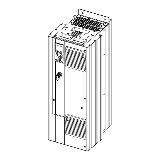
Mechanical Installation ® AutomationDrive FC 300 Design Guide 90-1200 kW 6.1.4 Mechanical Dimensions [12.8] [14.9] [9.7] [3.2] [7.1] [0.7] [3.9] [4.8] [5.1] [0.8] [3.1] [6.5] [7.9] [5.8] [33.2] [35.5] [33.2] [25.8] [26.5] [22.1] [20.0] [7.9] Illustration 6.7 Mechanical Dimensions, D1h 1 Ceiling 2 Air space outlet minimum 225 mm [8.9 in] [2.5]... - Page 102 Mechanical Installation ® AutomationDrive FC 300 Design Guide 90-1200 kW [16.5] [13.6] [14.9] [11.0] [3.8] [5.6] [0.7] [5.1] [0.8] [4.2] [8.3] [8.4] 1107 [12.6] [43.6] 1051 1050 [41.4] [5.8] [41.3] [33.7] [34.6] [28.3] [24.5] [10.7] Illustration 6.9 Mechanical Dimensions, D2h 1 Ceiling 2 Air space outlet minimum 225 mm [8.9 in] [2.9]...
- Page 103 Mechanical Installation ® AutomationDrive FC 300 Design Guide 90-1200 kW [9.8] [14.8] [7.1] [3.2] [1.0] [2.4] 122.5 [4.8] [0.7] [5.1] [0.8] 77.5 [3.1] [5.0] [7.9] [35.0] [33.2] [5.8] [35.8] [33.2] [25.8] [26.0] [19.5] [7.9] Illustration 6.11 Mechanical Dimensions, D3h 1 Ceiling 2 Air space outlet minimum 225 mm [8.9 in] [0.4] 3 Air space inlet minimum 225 mm [8.9 in]...
- Page 104 Mechanical Installation ® AutomationDrive FC 300 Design Guide 90-1200 kW [13.8] [14.8] [11.0] [1.5] [5.6] [0.7] [2.3] [5.1] [0.8] [4.2] 1122 [6.9] [8.4] [44.2] 1096 [12.6] [43.1] 1051 1050 [41.4] [41.3] [5.8] [33.7] [34.2] [24.1] [10.7] Illustration 6.13 Mechanical Dimensions, D4h 1 Ceiling [1.6] 2 Air space outlet minimum 225 mm [8.9 in]...
- Page 105 Mechanical Installation ® AutomationDrive FC 300 Design Guide 90-1200 kW [12.8] [12.1] [15] [10.9] [4.5] [7.1] [5.1] [4.8] [0.9] [3.1] [7.9] 16.1 [5.9] [6.3] 1324 1276 [52.1] [50.2] 1277 1111 [50.3] [43.7] 1107 [5.1] [43.6] [4.8] [28.8] [3.1] [7.9] [8.7] [7.9] Illustration 6.15 Mechanical Dimensions, D5h 1 Ceiling...
- Page 106 Mechanical Installation ® AutomationDrive FC 300 Design Guide 90-1200 kW [12.8] [15.0] [12.1] [4.5] [10.9] [5.1] [7.1] [4.8] [0.9] [3.1] [7.9] [6.3] [5.1] 1452 1663 1615 1617 [7.1] [65.5] [57.2] [63.6] 1447 [63.7] [57.0] [4.8] [3.1] [35.8] [7.9] [7.9] [22.0] Illustration 6.17 Mechanical Dimensions, D6h 1 Ceiling 2 Air space outlet minimum 225 mm [8.9 in]...
- Page 107 Mechanical Installation ® AutomationDrive FC 300 Design Guide 90-1200 kW [16.5] [16.2] [15.2] [14.7] [6.2] [5.1] [11] [0.9] [4.2] [8.4] [8.2] [6.3] [12.6] 1978 1953 [5.1] 1931 1760 [77.9] [76.9] 1754 [76] [69.3] [69.1] 1282 [50.5] [4.2] [8.4] [26.3] [12.6] Illustration 6.19 Mechanical Dimensions, D7h 1 Ceiling 2 Air space outlet minimum 225 mm [8.9 in]...
- Page 108 Mechanical Installation ® AutomationDrive FC 300 Design Guide 90-1200 kW [16.5] [16.2] [14.7] [16] [6.2] [5.1] [11] [0.9] [4.2] [8.4] [12.6] [8.5] [5.1] [6.4] 2284 2236 2259 [89.9] [88] [88.9] 2065 [81.3] 1699 [4.2] [66.9] 1400 [55.1] [8.4] [12.6] [38.3] Illustration 6.21 Mechanical Dimensions, D8h 1 Ceiling 2 Air space outlet minimum 225 mm [8.9 in]...
- Page 109 Mechanical Installation ® AutomationDrive FC 300 Design Guide 90-1200 kW IP21 AND IP54 / UL AND NEMA TYPE 1 AND 12 8.86 19.1 2X 13 1043 41.1 2000 (78.74) 1551 61.1 28.6 SIDE CABLE ENTRY KNOCK-OFF PLATE CABLE BASE BOTTOM CABLE ENTRY 15.4 (23.62) 19.4...
- Page 110 Mechanical Installation ® AutomationDrive FC 300 Design Guide 90-1200 kW IP00 / CHASSIS (5.5) (12.0) (7.3) (7.3) (1.5) 2X13 (2.5) (19.5) (1.0) (4.7) (0.5) (8.9) 1043 (41.1) 1547 1502 1320 (60.9) (59.1) (52.0) (6.3) (10.6) (6.2) (8.9) (21.2) (23.0) (0.9) (1.0) (1.0) (1.0)
- Page 111 Mechanical Installation ® AutomationDrive FC 300 Design Guide 90-1200 kW 1804 225.0 Ø29 (71.0) (8.85) (1.1) 2281 (89.8) 2206 (86.9) 1499 (59.0) (23.8) Illustration 6.25 Mechanical Dimensions, F2 Minimum clearance from ceiling Table 6.17 Legend to Illustration 6.25 MG34S202 - Rev. 2013-08-19...
- Page 112 Mechanical Installation ® AutomationDrive FC 300 Design Guide 90-1200 kW 225.0 2401 Ø29 (8.85) (94.5) (1.1) 2280 (89.7) 2205 (86.8) 1497 (58.9) (23.8) Illustration 6.26 Mechanical Dimensions, F4 Minimum clearance from ceiling Table 6.18 Legend to Illustration 6.26 MG34S202 - Rev. 2013-08-19...
- Page 113 Mechanical Installation ® AutomationDrive FC 300 Design Guide 90-1200 kW Frame size 90-132 kW 160-250 kW 90-132 kW 160-250 kW (380-500 V) (380-500 V) (380-500 V) (380-500 V) With Regeneration or Load Share 90-132 kW 160-315 kW 37-132 kW 160-315 kW Terminals (525-690 V) (525-690 V)
-
Page 114: Mechanical Dimensions, 12-Pulse Units
Mechanical Installation ® AutomationDrive FC 300 Design Guide 90-1200 kW 6.1.5 Mechanical Dimensions, 12-Pulse Units IP/21 NEMA 1 1400 m3/Hr 1970 m3/Hr 1160 Illustration 6.27 Mechanical Dimensions (mm), F8 MG34S202 - Rev. 2013-08-19... - Page 115 Mechanical Installation ® AutomationDrive FC 300 Design Guide 90-1200 kW 1400 IP/21 NEMA 1 2100 m3/Hr 1236 1970 m3/Hr 1160 Illustration 6.28 Mechanical Dimensions (mm), F9 MG34S202 - Rev. 2013-08-19...
- Page 116 Mechanical Installation ® AutomationDrive FC 300 Design Guide 90-1200 kW 1600 IP/21 NEMA 1 2800 m3/Hr 1648 3940 m3/Hr 2320 Illustration 6.29 Mechanical Dimensions (mm), F10 MG34S202 - Rev. 2013-08-19...
- Page 117 Mechanical Installation ® AutomationDrive FC 300 Design Guide 90-1200 kW 2400 IP/21 NEMA 1 4200 m3/Hr 2472 3940 m3/Hr 2320 Illustration 6.30 Mechanical Dimensions (mm), F11 MG34S202 - Rev. 2013-08-19...
- Page 118 Mechanical Installation ® AutomationDrive FC 300 Design Guide 90-1200 kW 2000 IP/21 NEMA 1 2800 m3/Hr 2472 4925 m3/Hr 2900 Illustration 6.31 Mechanical Dimensions (mm), F12 MG34S202 - Rev. 2013-08-19...
- Page 119 Mechanical Installation ® AutomationDrive FC 300 Design Guide 90-1200 kW 2800 IP/21 NEMA 1 4200 m3/Hr 2472 4925 m3/Hr 2900 Illustration 6.32 Mechanical Dimensions (mm), F13 Frame size High overload rated 250-400 kW 250-400 kW 450-630 kW 450-630 kW 710-800 kW 710-800 kW power - 160% (380-500 V)
-
Page 120: Mechanical Installation
Mechanical Installation ® AutomationDrive FC 300 Design Guide 90-1200 kW 6.2 Mechanical Installation Preparation for the mechanical installation of the frequency converter must be done carefully to ensure a proper fit and to avoid additional work during installation. The mechanical drawings in 6.1.4 Mechanical Dimensions provide more information about the space requirements. - Page 121 Mechanical Installation ® AutomationDrive FC 300 Design Guide 90-1200 kW (22.8) (30.6) (30.6) (30.6) Illustration 6.36 Front Clearance of IP21/IP54 Enclosure Type, Illustration 6.42 Front Clearance of IP21/IP54 Enclosure Type, Frame Size F1 Frame Size F10 2X578 (30.6) [22.8] [30.6] (2x) Illustration 6.43 Front Clearance of IP21/IP54 Enclosure Type, Illustration 6.37 Front Clearance of IP21/IP54 Enclosure Type,...
-
Page 122: Terminal Locations - Frame Size D
Mechanical Installation ® AutomationDrive FC 300 Design Guide 90-1200 kW 6.2.3 Terminal Locations - Frame Size D Take the following terminal positions into consideration when designing for cables access. Dimensions are shown in mm [in]. NOTICE Power cables are heavy and hard to bend. Consider the optimum position of the frequency converter to ensure easy installation of the cables. - Page 123 Mechanical Installation ® AutomationDrive FC 300 Design Guide 90-1200 kW SECTION B-B SECTION A-A MOTOR TERMINALS AND MAINS TERMINALS BRAKE TERMINALS MAINS TERMINAL MOTOR TERMINAL 331.2 211.1 GROUND 168.4 168.4 GROUND GROUND 143.4 143.4 GROUND 4X M10x20 STUD WITH NUT Illustration 6.48 Position of Power Connections, Frame Size D2h SECTION B-B SECTION A-A...
- Page 124 Mechanical Installation ® AutomationDrive FC 300 Design Guide 90-1200 kW 9 [ ] 0 [ ] Illustration 6.50 Terminal Locations, D5h with Disconnect Option Mains Terminals Brake Terminals Motor Terminals Earth/Ground Terminals Table 6.23 Legend to Illustration 6.50 MG34S202 - Rev. 2013-08-19...
- Page 125 Mechanical Installation ® AutomationDrive FC 300 Design Guide 90-1200 kW 28.6 24.5 20.4 20.1 0 [ ] Illustration 6.51 Terminal Locations, D5h with Brake Option Mains Terminals Brake Terminals Motor Terminals Earth/Ground Terminals Table 6.24 Legend to Illustration 6.51 MG34S202 - Rev. 2013-08-19...
- Page 126 Mechanical Installation ® AutomationDrive FC 300 Design Guide 90-1200 kW 18.0 Illustration 6.52 Terminal Locations, D6h with Contactor Option Mains Terminals TB6 Terminal block for contactor Brake Terminals Motor Terminals Earth/Ground Terminals Table 6.25 Legend to Illustration 6.52 MG34S202 - Rev. 2013-08-19...
- Page 127 Mechanical Installation ® AutomationDrive FC 300 Design Guide 90-1200 kW Illustration 6.53 Terminal Locations, D6h with Contactor and Disconnect Options Brake Terminals TB6 Terminal block for contactor Motor Terminals Earth/Ground Terminals Mains Terminals Table 6.26 Legend to Illustration 6.53 MG34S202 - Rev. 2013-08-19...
- Page 128 Mechanical Installation ® AutomationDrive FC 300 Design Guide 90-1200 kW 18.4 Illustration 6.54 Terminal Locations, D6h with Circuit Breaker Option Mains Terminals Brake Terminals Motor Terminals Earth/Ground Terminals Table 6.27 Legend to Illustration 6.54 MG34S202 - Rev. 2013-08-19...
- Page 129 Mechanical Installation ® AutomationDrive FC 300 Design Guide 90-1200 kW 21.4 20.3 16.2 15.6 14.7 0 [ ] Illustration 6.55 Terminal Locations, D7h with Disconnect Option Mains Terminals Motor Terminals Earth/Ground Terminals Brake Terminals Table 6.28 Legend to Illustration 6.55 MG34S202 - Rev.
- Page 130 Mechanical Installation ® AutomationDrive FC 300 Design Guide 90-1200 kW 1260 49.6 1202 47.3 1082 42.6 1034 40.7 1009 39.7 0 [ ] Illustration 6.56 Terminal Locations, D7h with Brake Option Mains Terminals Brake Terminals Motor Terminals Earth/Ground Terminals Table 6.29 Legend to Illustration 6.56 MG34S202 - Rev.
- Page 131 Mechanical Installation ® AutomationDrive FC 300 Design Guide 90-1200 kW 35.3 20.5 16.5 15.8 14.9 0 [ ] Illustration 6.57 Terminal Locations, D8h with Contactor Option TB6 Terminal block for contactor Motor Terminals Earth/Ground Terminals Brake Terminals Mains Terminals Table 6.30 Legend to Illustration 6.57 MG34S202 - Rev.
- Page 132 Mechanical Installation ® AutomationDrive FC 300 Design Guide 90-1200 kW 22.3 Illustration 6.58 Terminal Locations, D8h with Contactor and Disconnect Options TB6 Terminal block for contactor Mains Terminals Brake Terminals Motor Terminals Earth/Ground Terminals Table 6.31 Legend to Illustration 6.58 MG34S202 - Rev.
- Page 133 Mechanical Installation ® AutomationDrive FC 300 Design Guide 90-1200 kW 23.8 Illustration 6.59 Terminal Locations, D8h with Circuit Breaker Option Mains Terminals Brake Terminals Motor Terminals Earth/Ground Terminals Table 6.32 Legend to Illustration 6.59 MG34S202 - Rev. 2013-08-19...
-
Page 134: Terminal Locations - Frame Size E
Mechanical Installation ® AutomationDrive FC 300 Design Guide 90-1200 kW 6.2.4 Terminal Locations - Frame Size E Terminal Locations - Frame Size E1 Take the following position of the terminals into consideration when designing the cable access. Dimensions are shown in mm [in]. NOTICE Power cables are heavy and hard to bend. - Page 135 Mechanical Installation ® AutomationDrive FC 300 Design Guide 90-1200 kW NOTICE Power connections can be made to positions A or B. 492[19.4] 323[12.7] 0[0.0] 195[7.7] Illustration 6.61 IP21 (NEMA Type 1) and IP54 (NEMA Type 12) Enclosure Power Connection Positions MG34S202 - Rev.
- Page 136 Mechanical Installation ® AutomationDrive FC 300 Design Guide 90-1200 kW 19 Nm [14 FTa 453[17.8] 0[0.0] Illustration 6.62 IP21 (NEMA type 1) and IP54 (NEMA type 12) Enclosure Power Connection Positions (Detail B) MG34S202 - Rev. 2013-08-19...
- Page 137 Mechanical Installation ® AutomationDrive FC 300 Design Guide 90-1200 kW FASTENER TORQUE: M8 9.6 Nm [7 FT-LB] FASTENER TORQUE: M10 19 Nm [14 FT-LB] R/L1 91 S/L2 92 T/L3 93 19 Nm [14FT-LB] /T1 96 V/T2 97 V/T3 9 0[0.0] 144[5.7] 26[1.0] 26[1.0]...
- Page 138 Mechanical Installation ® AutomationDrive FC 300 Design Guide 90-1200 kW Terminal Locations - Frame Size E2 Take the following position of the terminals into consideration when designing the cable access. FASTENER TORQUE M8 9.6 Nm (7 FT-LB) FASTENER TORQUE M8 9.6 Nm (7 FT-LB) R/L1 91 S/L2 92 T/L3 93...
- Page 139 Mechanical Installation ® AutomationDrive FC 300 Design Guide 90-1200 kW 0[0.0] 0[0.0] 0[0.0] Illustration 6.66 IP00 Enclosure Power Connections, Position of Disconnect Switch Frame size Unit type Dimension for disconnect terminal, mm (in) IP00/CHASSIS 250/315 kW (400 V) and 381 (15.0) 245 (9.6) 334 (13.1) 423 (16.7)
-
Page 140: Terminal Locations - Frame Size F
Mechanical Installation ® AutomationDrive FC 300 Design Guide 90-1200 kW 6.2.5 Terminal Locations - Frame Size F The F-frames have 4 different sizes, F1, F2, F3, and F4. The F1 and F2 consist of an inverter cabinet on the right and rectifier cabinet on the left. - Page 141 Mechanical Installation ® AutomationDrive FC 300 Design Guide 90-1200 kW DC ‘-’ 1739.1 805.0 765.0 1694.1 DC ‘+’ 1654.1 710.0 Illustration 6.68 Terminal Locations - Regeneration Terminals for F1 and F3 Terminal Locations - Frame Size F2 and F4 308.3 [12.14] 253.1 [9.96] FASTENER TORQUE: MIO 19 Nm (14 FT -LB) FASTENER TORQUE: MIO 19 Nm (14 FT -LB)
- Page 142 Mechanical Installation ® AutomationDrive FC 300 Design Guide 90-1200 kW DC ‘-’ 1739.1 1203.2 1163.2 1694.1 DC ‘+’ 1654.1 1098.1 Illustration 6.70 Terminal Locations - Regeneration Terminals for F2 and F4 Terminal Locations - Rectifier (F1, F2, F3 and F4) CH22 CH22 CH22...
- Page 143 Mechanical Installation ® AutomationDrive FC 300 Design Guide 90-1200 kW Terminal Locations - Options Cabinet (F3 and F4) 1031.4[40.61] 939.0[36.97] 134.6[5.30] 0.0[0.00] 0.0[1.75] 244.4[1.75] 244.4[9.62] Illustration 6.72 Terminal Locations - Options Cabinet (Left, Front and Right Side View). Gland Plate is 42 mm below .0 Level. Earth/Ground bar Table 6.38 Legend to Illustration 6.72 MG34S202 - Rev.
- Page 144 Mechanical Installation ® AutomationDrive FC 300 Design Guide 90-1200 kW Terminal Locations - Options Cabinet with Circuit Breaker/Molded Case Switch (F3 and F4) 532.9 [20.98] 436.9 [17.20] 134.6 [5.30] 0.0 [0.00] 0.0 [0.00] 44.4 [1.75] 244.4 [9.62] Illustration 6.73 Terminal Locations - Options Cabinet with Circuit Breaker/Molded Case Switch (Left, Front and Right Side View). Gland Plate is 42 mm below .0 Level.
-
Page 145: Terminal Locations - Frame Size F, 12-Pulse
Mechanical Installation ® AutomationDrive FC 300 Design Guide 90-1200 kW 6.2.6 Terminal Locations - Frame Size F, 12-Pulse The 12-Pulse F-frame enclosures have 6 different sizes. The F8, F10, and F12 consist of an inverter cabinet on the right and a rectifier cabinet on the left. - Page 146 Mechanical Installation ® AutomationDrive FC 300 Design Guide 90-1200 kW Terminal Locations - Inverter Frame Size F10 and F11 308.3 [12.1] 253.1 [10.0] 180.3 [7.1] .0 [.0] 44.40 [1.75] 244.40 [9.62] Illustration 6.75 Terminal Locations - Inverter Cabinet. Gland Plate is 42 mm below .0 Level. Front View Left Side View Right Side View...
- Page 147 Mechanical Installation ® AutomationDrive FC 300 Design Guide 90-1200 kW Terminal Locations - Inverter Frame Size F12 and F13 308.3 [12.14] 253.1 [9.96] FASTENER TORQUE: MIO 19 Nm (14 FT -LB) FASTENER TORQUE: MIO 19 Nm (14 FT -LB) FASTENER TORQUE: MIO 19 Nm (14 FT -LB) U/T1 96 V/T2 97 W/T3 98...
- Page 148 Mechanical Installation ® AutomationDrive FC 300 Design Guide 90-1200 kW Terminal Locations - Rectifier (F10, F11, F12 and F13) 239.6 [ 9.43 ] U/T1 96 V/T2 97 W/T3 98 R2/L12 91-1 S2/L22 92-1 T2/L32 93-1 160.0 [ 6.30 ] R1/L11 S1/L21 T1/L31 93 56.6 [ 2.23 ]...
- Page 149 Mechanical Installation ® AutomationDrive FC 300 Design Guide 90-1200 kW Terminal Locations - Options Cabinet Frame Size F9 887.4 830.3 628.8 443.8 386.7 151.3 244.4 Illustration 6.78 Terminal Locations - Options Cabinet. Left Side View Front View Right Side View Table 6.45 Legend to Illustration 6.78 MG34S202 - Rev.
- Page 150 Mechanical Installation ® AutomationDrive FC 300 Design Guide 90-1200 kW Terminal Locations - Options Cabinet Frame Size F11/F13 547.8 440.4 151.3 244.4 Illustration 6.79 Terminal Locations - Options Cabinet. Left Side View Front View Right Side View Earth/Ground Bar Table 6.46 Legend to Illustration 6.79 MG34S202 - Rev.
-
Page 151: Gland/Conduit Entry - Ip21 (Nema 1) And Ip54 (Nema12)
Mechanical Installation ® AutomationDrive FC 300 Design Guide 90-1200 kW 6.2.7 Gland/Conduit Entry - IP21 (NEMA 1) and IP54 (NEMA12) [14.5] [1.0] [7.3] Cables are connected through the gland plate from the bottom. Remove the plate and plan where to place the entry for the glands or conduits. - Page 152 Mechanical Installation ® AutomationDrive FC 300 Design Guide 90-1200 kW [13.3] [6.6] [1.7] 62.5 202.8 130.0 [8.7] 98.6 [4.5] Illustration 6.84 E1, Bottom View Illustration 6.83 D7h & D8h, Bottom View 1 Mains Side 2 Motor Side 1 Mains Side 2 Motor Side Table 6.51 Legend to Illustration 6.84 Table 6.50 Legend to Illustration 6.83...
- Page 153 Mechanical Installation ® AutomationDrive FC 300 Design Guide 90-1200 kW 655.9 25.825 994.3 [39.146] 37.7 460.0 [1.485] [18.110] 216.5 199.5 [8.524] [7.854] 535.0 [21.063] 281.8 258.2 [11.096] [10.167] 533.0 35.5 [20.984] [1.398] 36.2 594.8 [1.425] [23.417] 1727.8 [68.024] Illustration 6.86 F2, Bottom View Cable conduit entry Table 6.53 Legend to Illustration 6.86 1265.3...
-
Page 154: Gland/Conduit Entry, 12-Pulse - Ip21 (Nema 1) And Ip54 (Nema12)
Mechanical Installation ® AutomationDrive FC 300 Design Guide 90-1200 kW 1252.8 994.3 634.7 (24.989) (49.321) (39.146) 37.7 (1.485) 2X 460.0 (18.110) 2X 216.5 199.5 (8.524) 535.0 (7.854) (21.063) 258.2 2X 281.8 (10.167) (11.096) 533 (20.984) 35.5 (1.398) 597.0 (23.504) 36.2 1130.0 (44.488) (1.425) 1191.8 (46.921) - Page 155 Mechanical Installation ® AutomationDrive FC 300 Design Guide 90-1200 kW 673,0 593,0 [ 26.50 ] [ 23.35 ] 460,0 [ 18.11 ] 37,2 [ 1.47 ] 199,5 [ 7.85 ] 535,0 [ 21 . 06 ] 258,5 [ 10.18 ] 37.2 533,0 [1.47]...
- Page 156 Mechanical Installation ® AutomationDrive FC 300 Design Guide 90-1200 kW 1670 . 0 593 . 0 [ 65 . 748 ] [ 23 . 346 ] 870 . 7 593 . 0 [ 34 . 252 ] 70 . 0 593 .
-
Page 157: Cooling And Airflow
Mechanical Installation ® AutomationDrive FC 300 Design Guide 90-1200 kW 1657 . 7 994 . 3 [ 65 . 2641 ] [ 39 . 146 ] 870 . 7 593 . 0 70 . 0 [ 34 . 252 ] 593 . - Page 158 Mechanical Installation ® AutomationDrive FC 300 Design Guide 90-1200 kW Drive size Airflow m3/h (cfm) Enclosure Drive type Frame size Door fan(s)/Top protection 380-480 V (T5) 525-690 V (T7) Heatsink fan(s) IP21/NEMA 1 or D1h, D5h, D6h IP54/NEMA 12 N110 to N160 N75 to N160 102 (60) 420 (250)
-
Page 159: Wall/Panel Mount Installation
Mechanical Installation ® AutomationDrive FC 300 Design Guide 90-1200 kW 27.3 45.9 89.3 115.7 Pressure Increase (Pa) Pressure Change Illustration 6.95 D-frame Derating vs. Pressure Change. Illustration 6.98 F1, F2, F3, F4 Frame Derating vs. Pressure Frequency Converter Airflow: 450 cfm (765 m Change. -
Page 160: Pedestal Installation Of E-Frames
Mechanical Installation ® AutomationDrive FC 300 Design Guide 90-1200 kW Illustration 6.99 Wall Mounting Spacer To install a pedestal-mounted D-frame unit, perform the following steps as shown in Illustration 6.100: Attach the pedestal to the back channel using 2 M10 nuts. Fasten 2 M5 screws through the back pedestal Illustration 6.100 Pedestal Hardware Installation flange into the pedestal drive mounting bracket. -
Page 161: Pedestal Installation Of F-Frames
Mechanical Installation ® AutomationDrive FC 300 Design Guide 90-1200 kW 6.2.13 Pedestal Installation of F-frames The F-frame frequency converters are shipped with a pedestal. The F-frame pedestals use 8 bolts instead of 4, as shown in Illustration 6.102. Illustration 6.103 Fastener Location Detail 1 M8x60 mm bolt 2 M10x30 mm bolt Table 6.63 Legend to Illustration 6.103... -
Page 162: Electrical Installation
Electrical Installation ® AutomationDrive FC 300 Design Guide 90-1200 kW 7 Electrical Installation 7.1 Connections 7.1.1 Torque Settings When tightening electrical connections, it is important to use a torque wrench to obtain the correct torque. Torque that is too low or too high results in a bad electrical connection. See the torque settings in Table 7.1. -
Page 163: Power Connections
Electrical Installation ® AutomationDrive FC 300 Design Guide 90-1200 kW 7.1.2 Power Connections Make the screen connections with the largest possible NOTICE surface area (cable clamp) by using the installation devices within the frequency converter. All cabling must comply with national and local regulations on cable cross-sections and ambient Cable-length and cross-section temperature. - Page 164 Electrical Installation ® AutomationDrive FC 300 Design Guide 90-1200 kW D-frame Interior Components (IP 21/54 NEMA 1/12) 13 (IP 20/Chassis) Illustration 7.3 D-frame Interior Components Illustration 7.4 Close-up View: LCP and Control Functions LCP (Local Control Panel) Relay 2 (04, 05, 06) RS-485 serial bus connector 10 Lifting ring Digital I/O and 24 V power supply...
- Page 165 Electrical Installation ® AutomationDrive FC 300 Design Guide 90-1200 kW Terminal Locations - D1h/D2h Take the following position of the terminals into consideration when designing the cable access. Illustration 7.5 Position of Earth Terminals IP21 (NEMA Type 1) and IP54 (NEMA Type 12), D1h/D2h MG34S202 - Rev.
- Page 166 Electrical Installation ® AutomationDrive FC 300 Design Guide 90-1200 kW Terminal Locations - D3h/D4h Take the following position of the terminals into consideration when designing the cable access. Illustration 7.6 Position of Earth Terminals IP20 (Chassis), D3h/D4h Earth Terminals Table 7.4 Legend to Illustration 7.5 and Illustration 7.6 MG34S202 - Rev.
- Page 167 Electrical Installation ® AutomationDrive FC 300 Design Guide 90-1200 kW Terminal Locations - D5h Take the following position of the terminals into consideration when designing the cable access. 9 [ ] 0 [ ] Illustration 7.7 Terminal Locations, D5h with Disconnect Option Mains Terminals Motor Terminals Brake Terminals...
- Page 168 Electrical Installation ® AutomationDrive FC 300 Design Guide 90-1200 kW 28.6 24.5 20.4 20.1 0 [ ] Illustration 7.8 Terminal Locations, D5h with Brake Option Mains Terminals Motor Terminals Brake Terminals Earth/Ground Terminals Table 7.6 Legend to Illustration 7.8 MG34S202 - Rev. 2013-08-19...
- Page 169 Electrical Installation ® AutomationDrive FC 300 Design Guide 90-1200 kW Terminal Locations - D6h Take the following position of the terminals into consideration when designing the cable access. 18.0 Illustration 7.9 Terminal Locations, D6h with Contactor Option Mains Terminals Motor Terminals TB6 Terminal block for contactor Earth/Ground Terminals Brake Terminals...
- Page 170 Electrical Installation ® AutomationDrive FC 300 Design Guide 90-1200 kW Illustration 7.10 Terminal Locations, D6h with Contactor and Disconnect Options Brake Terminals Earth/Ground Terminals TB6 Terminal block for contactor Mains Terminals Motor Terminals Table 7.8 Legend to Illustration 7.10 MG34S202 - Rev. 2013-08-19...
- Page 171 Electrical Installation ® AutomationDrive FC 300 Design Guide 90-1200 kW 18.4 Illustration 7.11 Terminal Locations, D6h with Circuit Breaker Option Mains Terminals Motor Terminals Brake Terminals Earth/Ground Terminals Table 7.9 Legend to Illustration 7.11 MG34S202 - Rev. 2013-08-19...
- Page 172 Electrical Installation ® AutomationDrive FC 300 Design Guide 90-1200 kW Terminal Locations - D7h Take the following position of the terminals into consideration when designing the cable access. 21.4 20.3 16.2 15.6 14.7 0 [ ] Illustration 7.12 Terminal Locations, D7h with Disconnect Option Mains Terminals Earth/Ground Terminals Motor Terminals...
- Page 173 Electrical Installation ® AutomationDrive FC 300 Design Guide 90-1200 kW 1260 49.6 1202 47.3 1082 42.6 1034 40.7 1009 39.7 0 [ ] Illustration 7.13 Terminal Locations, D7h with Brake Option Mains Terminals Motor Terminals Brake Terminals Earth/Ground Terminals Table 7.11 Legend to Illustration 7.13 MG34S202 - Rev.
- Page 174 Electrical Installation ® AutomationDrive FC 300 Design Guide 90-1200 kW Terminal Locations - D8h Take the following position of the terminals into consideration when designing the cable access. 35.3 20.5 16.5 15.8 14.9 0 [ ] Illustration 7.14 Terminal Locations, D8h with Contactor Option TB6 Terminal block for contactor Brake Terminals Motor Terminals...
- Page 175 Electrical Installation ® AutomationDrive FC 300 Design Guide 90-1200 kW 22.3 Illustration 7.15 Terminal Locations, D8h with Contactor and Disconnect Options TB6 Terminal block for contactor Motor Terminals Mains Terminals Earth/Ground Terminals Brake Terminals Table 7.13 Legend to Illustration 7.15 MG34S202 - Rev.
- Page 176 Electrical Installation ® AutomationDrive FC 300 Design Guide 90-1200 kW 23.8 Illustration 7.16 Terminal Locations, D8h with Circuit Breaker Option Mains Terminals Motor Terminals Brake Terminals Earth/Ground Terminals Table 7.14 Legend to Illustration 7.16 MG34S202 - Rev. 2013-08-19...
- Page 177 Electrical Installation ® AutomationDrive FC 300 Design Guide 90-1200 kW Terminal Locations - E1 Take the following position of the terminals into consideration when designing the cable access. 492[19.4] 323[12.7] 0[0.0] 195[7.7] Illustration 7.17 IP21 (NEMA Type 1) and IP54 (NEMA Type 12) Enclosure Power Connection Positions Front View of Unit Table 7.15 Legend to Illustration 7.17 MG34S202 - Rev.
- Page 178 Electrical Installation ® AutomationDrive FC 300 Design Guide 90-1200 kW 19 Nm [14 FTa 453[17.8] 0[0.0] Illustration 7.18 IP21 (NEMA Type 1) and IP54 (NEMA Type 12) Enclosure Power Connection Positions (Detail B) MG34S202 - Rev. 2013-08-19...
- Page 179 Electrical Installation ® AutomationDrive FC 300 Design Guide 90-1200 kW FASTENER TORQUE: M8 9.6 Nm [7 FT-LB] FASTENER TORQUE: M10 19 Nm [14 FT-LB] R/L1 91 S/L2 92 T/L3 93 19 Nm [14FT-LB] /T1 96 V/T2 97 V/T3 9 0[0.0] 144[5.7] 26[1.0] 26[1.0]...
- Page 180 Electrical Installation ® AutomationDrive FC 300 Design Guide 90-1200 kW Terminal Locations - Frame Size E2 FASTENER TORQUE M8 9.6 Nm (7 FT-LB) FASTENER TORQUE M8 9.6 Nm (7 FT-LB) R/L1 91 S/L2 92 T/L3 93 186[7.3] U/T1 96 V/T2 97 W/T3 98 17[0.7] 0[0.0]...
- Page 181 Electrical Installation ® AutomationDrive FC 300 Design Guide 90-1200 kW 0[0.0] 0[0.0] 0[0.0] Illustration 7.22 IP00 Enclosure Power Connections, Position of Disconnect Switch NOTICE The power cables are heavy and difficult to bend. Consider the optimum position of the frequency converter to ensure easy cable installation.
- Page 182 Electrical Installation ® AutomationDrive FC 300 Design Guide 90-1200 kW NOTICE The F-Frames have 4 different sizes - F1, F2, F3 and F4. The F1 and F2 consist of an inverter cabinet on the right and rectifier cabinet on the left. The F3 and F4 are F1 and F2 units, respectively, with an additional options cabinet to the left of the rectifier.
- Page 183 Electrical Installation ® AutomationDrive FC 300 Design Guide 90-1200 kW Terminal Locations - Frame Size F2 and F4 Take the following position of the terminals into consideration when designing the cable access. 308.3 [12.14] 253.1 [9.96] FASTENER TORQUE: MIO 19 Nm (14 FT -LB) FASTENER TORQUE: MIO 19 Nm (14 FT -LB) FASTENER TORQUE: MIO 19 Nm (14 FT -LB) U/T1 96...
- Page 184 Electrical Installation ® AutomationDrive FC 300 Design Guide 90-1200 kW Terminal Locations - Rectifier (F1, F2, F3 and F4) Take the following position of the terminals into consideration when designing the cable access. CH22 CH22 CH22 CH22 CH22 CH22 CTI25MB CTI25MB 435.5 [17.15] 343.1 [13.51]...
- Page 185 Electrical Installation ® AutomationDrive FC 300 Design Guide 90-1200 kW Terminal Locations - Options Cabinet (F3 and F4) Take the following position of the terminals into consideration when designing the cable access. 1031.4[40.61] 939.0[36.97] 134.6[5.30] 0.0[0.00] 0.0[1.75] 244.4[1.75] 244.4[9.62] Illustration 7.29 Terminal Locations - Options Cabinet. Gland Plate is 42 mm below .0 Level. Left Side Right Side Front Side...
- Page 186 Electrical Installation ® AutomationDrive FC 300 Design Guide 90-1200 kW Terminal Locations - Options Cabinet with Circuit Breaker/Molded Case Switch (F3 and F4) Take the following position of the terminals into consideration when designing the cable access. 532.9 [20.98] 436.9 [17.20] 134.6 [5.30] 0.0 [0.00] 0.0 [0.00]...
-
Page 187: Power Connections 12-Pulse Frequency Converters
Electrical Installation ® AutomationDrive FC 300 Design Guide 90-1200 kW 7.1.3 Power Connections 12-Pulse Frequency Converters NOTICE All cabling must comply with national and local regulations on cable cross-sections and ambient temperature. UL applications require 75 °C copper conductors. Non-UL applications can use 75 and 90 °C copper conductors. The power cable connections are situated as shown in Illustration 7.31. - Page 188 If one of the 6-pulse modular rectifiers becomes inoperable, it is possible to operate the frequency converter at reduced load with a single 6-pulse rectifier. Contact Danfoss for reconnection details. No paralleling of mains cabling is shown here. A 12-pulse frequency converter used as a 6-pulse should have mains cables of equal numbers and lengths.
- Page 189 Electrical Installation ® AutomationDrive FC 300 Design Guide 90-1200 kW NOTICE Use mains cables of equal length ( ±10%) and the same wire size for all 3 phases on both rectifier sections. Screening of Cables Avoid installation with twisted screen ends (pigtails). They spoil the screening effect at higher frequencies.
-
Page 190: 12-Pulse Transformer Selection Guidelines
Electrical Installation ® AutomationDrive FC 300 Design Guide 90-1200 kW 7.1.4 12-Pulse Transformer Selection Guidelines Transformers used in conjunction with 12-Pulse frequency converters must conform to the following specifications. Loading is based on 12-pulse K-4 rated transformer with 0.5% voltage and impedance balance between secondary windings. Leads from the transformer to the input terminals on the frequency converter are required to be equal length within 10%. -
Page 191: Fuses And Circuit Breakers
NOTICE These recommendations do not cover Danfoss recommends the fuses from the following tables. branch circuit protection for UL. Selecting the proper fuses and circuit breakers minimises damage due to an over-current condition within the Short-Circuit Protection frequency converter. -
Page 192: Power/Semiconductor Fuse Size
Electrical Installation ® AutomationDrive FC 300 Design Guide 90-1200 kW 7.2.4 Power/Semiconductor Fuse Size Fuses or Circuit Breakers are mandatory to comply with IEC 60364. Enclosure size FC 300 Model [kW] Recommended Recommended fuse size maximum fuse N90K aR-315 aR-315 N110 aR-350 aR-350... -
Page 193: Power/Semiconductor Fuse Options
Electrical Installation ® AutomationDrive FC 300 Design Guide 90-1200 kW 7.2.5 Power/Semiconductor Fuse Options Power Fuse Options size Bussman Littelfuse PN Littelfuse Bussmann Siba PN Ferraz-Shawmut Ferraz-Shawmut PN Ferraz-Shawmut PN (Europe) (North America) N90K 170M2619 LA50QS300-4 L50S-300 FWH-300A 20 189 A50QS300-4 6,9URD31D08A0315 A070URD31KI0315... - Page 194 Electrical Installation ® AutomationDrive FC 300 Design Guide 90-1200 kW VLT© Model Bussmann PN Siba PN Ferraz-Shawmut European PN Ferraz-Shawmut North American PN N55k T7 170M2616 20 610 31.160 6,9URD30D08A0160 A070URD30KI0160 N75k T7 170M2619 20 610 31.315 6,9URD31D08A0315 A070URD31KI0315 N90k T7 170M2619 20 610 31.315 6,9URD31D08A0315...
-
Page 195: Supplementary Fuses
Electrical Installation ® AutomationDrive FC 300 Design Guide 90-1200 kW 7.2.6 Supplementary Fuses Supplementary Fuses Frame size Bussmann PN Rating LPJ-21/2SP 2.5 A, 600 V Table 7.39 D-frame Anti-Condensation Heater Fuse Recommendation NOTICE If a D-frame frequency converter comes with an anti-condensation heater, the heater must be powered, controlled, and protected by the installing contractor. -
Page 196: High Power Fuses 12-Pulse
Electrical Installation ® AutomationDrive FC 300 Design Guide 90-1200 kW Frame Size Bussmann PN Rating GMC-800 MA 800 mA, 250 V Table 7.45 NAMUR Fuse Frame size Bussmann PN Rating Alternative fuses LP-CC-6 6 A, 600 V Any listed Class CC, 6 A Table 7.46 Safety Relay Coil Fuse with PILZ Relay 7.2.7 High Power Fuses 12-Pulse The fuses below are suitable for use on a circuit capable of delivering 100,000 A... -
Page 197: Supplementary Fuses - High Power
Electrical Installation ® AutomationDrive FC 300 Design Guide 90-1200 kW Size/Type Bussmann PN* Rating Siba P630 170M8611 1100 A, 1000 V 20 781 32. 1000 P710 170M8611 1100 A, 1000 V 20 781 32. 1000 P800 170M8611 1100 A, 1000 V 20 781 32. -
Page 198: Disconnectors And Contactors
Electrical Installation ® AutomationDrive FC 300 Design Guide 90-1200 kW Default breaker settings Frame Power & Voltage Type size Trip level [A] Time [s] P450 380-500 V & P630-P710 Merlin Gerin 525-690 V NPJF36120U31AABSCYP 1200 P500-P630 380-500 V & P800 Merlin Gerin 525-690 V NRJF36200U31AABSCYP... -
Page 199: Mains Disconnects, 12-Pulse
Electrical Installation ® AutomationDrive FC 300 Design Guide 90-1200 kW 7.3.2 Mains Disconnects, 12-Pulse Frame size Power Type 380-500 V P250 ABB OETL-NF600A P315 ABB OETL-NF600A P355 ABB OETL-NF600A P400 ABB OETL-NF600A P450 ABB OETL-NF800A P500 ABB OETL-NF800A P560 ABB OETL-NF800A P630 ABB OT800U21 P710... -
Page 200: Additional Motor Information
Electrical Installation ® AutomationDrive FC 300 Design Guide 90-1200 kW 7.4 Additional Motor Information 7.4.1 Motor Cable common point of a phase. The recommended common point is the motor terminals. For example, if inverter module A used a 100 m cable, then subsequent inverter modules could use a cable between 90-110 m in length. -
Page 201: Parallel Connection Of Motors
Electrical Installation ® AutomationDrive FC 300 Design Guide 90-1200 kW 7.4.2 Parallel Connection of Motors The frequency converter can control several parallel-connected motors. When using parallel motor connection, observe the following points: • Run applications with parallel motors in U/F mode (volts per hertz). •... -
Page 202: Motor Insulation
Table 7.66. If a • Try to ensure that the line voltage is balanced to motor has lower insulation rating, Danfoss recommends ground. This can be difficult for IT, TT, TN-CS, or using a dU/dt or sine wave filter. - Page 203 Electrical Installation ® AutomationDrive FC 300 Design Guide 90-1200 kW Illustration 7.38 Profibus Top Entry Kit, Installed Illustration 7.36 Control Card Wiring Path for the F1/F3. Control Card Wiring for the F2/F4 Use the Same Path In the D- and E-Frame frequency converters, it is possible to connect the fieldbus from the top of the unit, as shown in the following illustrations.
-
Page 204: Control Terminals
Electrical Installation ® AutomationDrive FC 300 Design Guide 90-1200 kW 7.5.3 Control Terminals Drawing Reference Numbers: 10-pole plug digital I/O 3-pole plug RS-485 Bus 6-pole analog I/O USB Connection Illustration 7.41 Location of Switches S801, S201, and S202 (Left to Right) 7.5.5 Installing Control Terminals Control Terminals To mount the cable to the terminal, perform the following... -
Page 205: Basic Wiring Example
Electrical Installation ® AutomationDrive FC 300 Design Guide 90-1200 kW 7.5.6 Basic Wiring Example Mount the terminals from the accessory bag to the front of the frequency converter. Connect terminals 18, 27, and 37 to +24 V (terminal 12/13) Default Settings: 18=Start, 5-10 Terminal 18 Digital Input [9] 27=Stop inverse, 5-12 Terminal 27 Digital Input [6] 37=Safe torque off inverse... -
Page 206: Installing Control Cables
Electrical Installation ® AutomationDrive FC 300 Design Guide 90-1200 kW 7.5.7 Installing Control Cables Electrical Installation 230 VAC Anti-condensation heater (optional) 50/60Hz (optional) TB6 Contactor 230 VAC 50/60Hz 91 (L1) (U) 96 3 Phase (V) 97 92 (L2) power (W) 98 93 (L3) input (PE) 99... - Page 207 Electrical Installation ® AutomationDrive FC 300 Design Guide 90-1200 kW 91 (L1) (U) 96 3 Phase (V) 97 92 (L2) power 93 (L3) (W) 98 input (PE) 99 Motor Switch Mode DC bus 88 (-) Power Supply 89 (+) 10Vdc 24Vdc (R+) 82 Brake...
- Page 208 Electrical Installation ® AutomationDrive FC 300 Design Guide 90-1200 kW Input Polarity of Control Terminals PNP (Source) Digital input wiring Illustration 7.45 Input Polarity of Control Terminals (PNP Source) Illustration 7.47 Shield Termination and Strain Relief of Control Cable NPN (Sink) Digital input wiring Illustration 7.46 Input Polarity of Control Terminals (NPN Sink) NOTICE...
-
Page 209: 12-Pulse Control Cables
Electrical Installation ® AutomationDrive FC 300 Design Guide 90-1200 kW 7.5.8 12-Pulse Control Cables CONTROL CARD CONNCECTION Switch Mode Power Supply 10Vdc 24Vdc 15mA 130/200mA 50 (+10 V OUT) +10 Vdc S202 -10 Vdc 53 (A IN) +10 Vdc ON/I=0-20mA 0/4-20 mA S201 OFF/U=0-10V... - Page 210 Electrical Installation ® AutomationDrive FC 300 Design Guide 90-1200 kW CUSTOMER SUPPLIED 24V RET. CONTROL CARD PIN 20 REGEN (TERMINAL JUMPERED TOGETHER) TERMINALS CUSTOMER SUPPLIED 24V CUSTOMER SUPPLIED (TERMINAL JUMPERED TOGETHER) MCB 113 PIN X46/1 MCB 113 PIN X46/3 MCB 113 PIN X46/5 MCB 113 PIN X46/7 MCB 113 PIN X46/9 PILZ...
-
Page 211: Relay Output D Frame
Electrical Installation ® AutomationDrive FC 300 Design Guide 90-1200 kW Input Polarity of Control Terminals Relay 2 • Terminal 04: common • PNP (Source) Terminal 05: normally open 400 V AC Digital input wiring • Terminal 06: normally closed 240 V AC Relay 1 and relay 2 are programmed in 5-40 Function Relay, 5-41 On Delay, Relay, and 5-42 Off Delay, Relay. -
Page 212: Brake Resistor Temperature Switch
88, 89 DC Bus 400Vac, 2A Table 7.69 DC Bus Terminals Contact Danfoss if further information is required. 7.6.2 Load Sharing Illustration 7.53 E- and F-Frame Additional Relay Outputs Load Sharing calls for extra equipment and safety consid- erations. For further information, Load Sharing Application 7.5.11 Brake Resistor Temperature Switch... -
Page 213: How To Connect A Pc To The Frequency Converter
USB cable. When connecting the PC to the frequency converter Carry out a high voltage test by short-circuiting terminals through a USB cable, Danfoss recommends using a USB U, V, W, L , and L . -
Page 214: Earthing
• Safety earthing: allowed but not recommended. See also 2.3.3 Danfoss The frequency converter has a high leakage Frequency Converter and CE Labelling, 3.5 General Aspects of current and must be earthed appropriately for EMC, 3.5.2 EMC Test Results, and 7.8.3 Earthing of Screened... - Page 215 Electrical Installation ® AutomationDrive FC 300 Design Guide 90-1200 kW Illustration 7.56 shows an example of an EMC-correct electrical installation of an IP 20 frequency converter. The frequency converter is fitted in an installation cabinet with an output contactor and connected to a PLC, which is installed in a separate cabinet.
-
Page 216: Use Of Emc-Correct Cables
7.8.2 Use of EMC-Correct Cables Correct Screening The preferred method is to secure control and serial Danfoss recommends braided screened/armoured cables to communication cables with screening clamps at both ends optimise EMC immunity of the control cables and the EMC to ensure best possible high frequency cable contact. -
Page 217: Rfi Switch
25 m, This terminal is connected to earth via an internal RC link. Danfoss recommends setting the 14-50 RFI Filter to [ON]. Use twisted-pair cables to reduce interference between Refer also to the Application Note, VLT on IT Mains, MN50P. -
Page 218: The Effect Of Harmonics In A Power Distribution System
Where additional harmonic suppression is required, Danfoss offers the following mitigation equipment: A commonly used term for describing the impedance of a grid is the short circuit ratio (R ). -
Page 219: Harmonic Calculation
Choose between complete or reduced AMA Auto Tune. If a Sine-wave filter is mounted, run only Use the free Danfoss MCT 31 calculation software to the reduced AMA, or remove the Sine-wave filter determine the degree of voltage pollution on the grid and during the AMA procedure. -
Page 220: Application Examples
Application Examples ® AutomationDrive FC 300 Design Guide 90-1200 kW 8 Application Examples Parameters Function Setting 8.1 Automatic Motor Adaptation (AMA) 1-29 Automatic +24 V NOTICE Motor [1] Enable +24 V Adaptation complete D IN A jumper wire may be required between terminal 12 (or (AMA) D IN 13) and terminal 27 for the frequency converter to... -
Page 221: Start/Stop
Application Examples ® AutomationDrive FC 300 Design Guide 90-1200 kW Parameters Speed Function Setting 6-12 Terminal 53 4 mA* +24 V Low Current +24 V D IN 6-13 Terminal 53 20 mA* D IN High Current 6-14 Terminal 53 0 RPM Start (18) D IN Low Ref./Feedb. -
Page 222: External Alarm Reset
Application Examples ® AutomationDrive FC 300 Design Guide 90-1200 kW Parameters Function Setting 8.5 Speed Reference with Manual 5-10 Terminal 18 [8] Start +24 V Potentiometer Digital Input +24 V 5-11 Terminal 19 [10] D IN Parameters D IN Digital Input Reversing* Function Setting... -
Page 223: Speed Up/Down
Application Examples ® AutomationDrive FC 300 Design Guide 90-1200 kW 8.6 Speed Up/Down 8.7 RS-485 Network Connection Parameters Parameters Function Setting Function Setting 5-10 Terminal 18 [8] Start* 8-30 Protocol +24 V +24 V Digital Input 8-31 Address +24 V +24 V 5-12 Terminal 27 [19] Freeze... -
Page 224: Motor Thermistor
Application Examples ® AutomationDrive FC 300 Design Guide 90-1200 kW 8.8 Motor Thermistor 8.9 Relay Setup with Smart Logic Control CAUTION Parameters Thermistors must use reinforced or double insulation Function Setting to meet PELV insulation requirements. 4-30 Motor +24 V Feedback Loss +24 V Parameters... -
Page 225: Mechanical Brake Control
Application Examples ® AutomationDrive FC 300 Design Guide 90-1200 kW 8.10 Mechanical Brake Control Parameters Function Setting 5-40 Function [32] Mech. +24 V Relay brake ctrl. +24 V 5-10 Terminal 18 [8] Start* D IN D IN Digital Input 5-11 Terminal 19 [11] Start D IN Digital Input... -
Page 226: Closed Loop Drive System
Application Examples ® AutomationDrive FC 300 Design Guide 90-1200 kW 8.13 Closed Loop Drive System If the frequency converter is at the torque limit and a stop command is activated, terminal 29 Output (programmed to [27] Torque limit and stop) is activated. The signal to terminal 27 changes from 'logic 1' to 'logic 0', and the A closed loop drive system usually consists of the motor starts to coast, thereby ensuring that the hoist stops... -
Page 227: Options And Accessories
AutomationDrive FC 300 Design Guide 90-1200 kW 9 Options and Accessories 9.1 Options and Accessories Danfoss offers a wide range of options and accessories for When installing a C option, a mounting kit is required. For ® a list of mounting kit ordering numbers, refer to 5 How to the VLT AutomationDrive. -
Page 228: Galvanic Isolation In The Mcb
Options and Accessories ® AutomationDrive FC 300 Design Guide 90-1200 kW FC Series Control card (FC 100/200/300) MCB 101 B slot General Purpose I/O Code No. 130BXXXX SW. ver. XX.XX 24 V General Purpose I/O option MCB 101 24 V X30/ DIG &... -
Page 229: Digital Inputs - Terminal X30/1-4
Options and Accessories ® AutomationDrive FC 300 Design Guide 90-1200 kW 9.2.2 Digital Inputs - Terminal X30/1-4 Digital Input Number of digital inputs 4 (6) Terminal number 18, 19, 27, 29, 32, 33 Logic PNP or NPN Voltage level 0-24 V DC Voltage level, logic 0' PNP (GND=0 V) <5 V DC Voltage level, logic 1' PNP (GND=0 V) -
Page 230: Encoder Option Mcb
Options and Accessories ® AutomationDrive FC 300 Design Guide 90-1200 kW • ® Hiperface Encoder: Absolute and Sine-Cosine (Stegmann/SICK) 9.3 Encoder Option MCB 102 • EnDat encoder: Absolute and Sine-Cosine (Heidenhain) Supports version 2.1 The encoder module can be used as a feedback source for •... -
Page 231: Resolver Option Mcb
Options and Accessories ® AutomationDrive FC 300 Design Guide 90-1200 kW 5 V GND 24 V Illustration 9.6 Rotation Direction 9.4 Resolver Option MCB 103 MCB 103 Resolver option is used for interfacing resolver Illustration 9.4 Incremental Encoder ® motor feedback to VLT AutomationDrive. - Page 232 Options and Accessories ® AutomationDrive FC 300 Design Guide 90-1200 kW MCB 103 Option B Resolver Input SW. ver. X.XX Code No. X32/ LED 1 REF OK LED 2 COS OK LED 3 SIN OK LED NA REF+ REF- Rotor COS+ COS- θ...
-
Page 233: Relay Option Mcb
Options and Accessories ® AutomationDrive FC 300 Design Guide 90-1200 kW 1-00 Configuration Mode [1] Speed closed loop 1-01 Motor Control Principle [3] Flux with feedback 1-10 Motor Construction [1] PM, non salient SPM 1-24 Motor Current Nameplate 1-25 Motor Nominal Speed Nameplate 1-26 Motor Cont. - Page 234 Options and Accessories ® AutomationDrive FC 300 Design Guide 90-1200 kW Relay 7 Relay 8 Relay 9 DISMOUNT RELAY CARD TO ACCESS RS485 TERMINATION (S801) OR CURRENT/VOLTAGE SWITCHES (S201, S202) Illustration 9.11 Disconnect Relay Terminals Illustration 9.10 A5, B1-B4, and C1-C4 IMPORTANT ! The label MUST be placed on the LCP frame as shown in Illustration 9.10 to meet UL approval.
-
Page 235: Back-Up Option Mcb
Options and Accessories ® AutomationDrive FC 300 Design Guide 90-1200 kW 9.6 24 V Back-Up Option MCB 107 An external 24 V DC supply can be installed for low-voltage supply to the control card and any installed options card, enabling full operation of the LCP without connection to the mains. External 24 V DC Supply Specification 24 V DC ±15% (max. - Page 236 Options and Accessories ® AutomationDrive FC 300 Design Guide 90-1200 kW from X44/10. 5-19 Terminal 37 Safe Stop must be ATEX Certification with FC 302 configured to the desired Safe Torque Off functionality. The MCB 112 has been certified for ATEX, which means Default is Safe Torque Off alarm.
-
Page 237: Mcb 113 Extended Relay Card
German NAMUR NE37 recommendations. ® The MCB 113 is a standard C1-option for the Danfoss VLT AutomationDrive and is detected automatically after mounting. For information on mounting and installing the option, see 9.1.3 Slot C. - Page 238 Options and Accessories ® AutomationDrive FC 300 Design Guide 90-1200 kW Electrical Data Relays Numbers 4 SPDT Load at 250 V AC/30 V DC Load at 250 V AC/30 V DC with cos=0.4 3.5 A Over voltage category (contact-earth) Over voltage category (contact-contact) Combination of 250 V and 24 V signals Possible with one unused relay in between Maximum thru-put delay...
-
Page 239: Brake Resistors
For the FC 300, Danfoss can supply a Sine-wave filter to dampen the acoustic motor noise. The filter reduces the ramp-up time of the voltage, the peak load voltage U PEAK MG34S202 - Rev. -
Page 240: High Power Options
Options and Accessories ® AutomationDrive FC 300 Design Guide 90-1200 kW and the ripple current ΔI to the motor. This results in the heater is controlled by customer-supplied 230 V AC. For best results, operate the heater only when the unit is not current and voltage becoming almost sinusoidal, which running. -
Page 241: Circuit Breaker
Options and Accessories ® AutomationDrive FC 300 Design Guide 90-1200 kW NOTICE NAMUR terminals NAMUR is an international association of automation When UL listing is required and the frequency converter technology users in the process industries, primarily is supplied with a contactor, the customer must provide chemical and pharmaceutical industries in Germany. - Page 242 Options and Accessories ® AutomationDrive FC 300 Design Guide 90-1200 kW • Safe Stop with Pilz Relay Analog current or analog voltage Provides a solution for the "Emergency Stop" option Additional features: without the contactor in F-Frame frequency converters. • One universal output, configurable for analog Manual motor starters voltage or analog current...
-
Page 243: Installation And Set-Up
RS-485 Installation and Set... ® AutomationDrive FC 300 Design Guide 90-1200 kW 10 RS-485 Installation and Set-up 10.1 Overview RS-485 is a 2-wire bus interface compatible with multi-drop network topology. Nodes can be connected as a bus, or via drop cables from a common trunk line. A total of 32 RS 232 nodes can be connected to one network segment. -
Page 244: Installation And Set-Up
Stop The FC protocol, also referred to as FC bus or Standard Parity bit bus, is the Danfoss standard fieldbus. It defines an access Illustration 10.4 Character (Byte) technique according to the master/follower principle for communications via a serial bus. -
Page 245: Telegram Structure
RS-485 Installation and Set... ® AutomationDrive FC 300 Design Guide 90-1200 kW 10.7.2 Telegram Structure The 10 represents the fixed characters, while the “n’” is variable (depending on the length of the text). Each telegram has the following structure: 10.7.4 Frequency Converter Address (ADR) Start character (STX)=02 Hex Two different address formats are used. -
Page 246: The Pke Field
RS-485 Installation and Set... ® AutomationDrive FC 300 Design Guide 90-1200 kW Parameter block The parameter block is used to transfer parameters between master and follower. The data block is made up of 12 bytes (6 words) and also contains the process block. PCD1 PCD2 high... -
Page 247: Parameter Number (Pnu)
RS-485 Installation and Set... ® AutomationDrive FC 300 Design Guide 90-1200 kW If the command cannot be performed, the follower sends block. Serial communication is only capable of reading this response: parameters containing data type 9 (text string). 0111 Command cannot be performed - and issues the following fault report in the parameter 15-40 FC Type to 15-53 Power Card Serial Number contain value (PWE):... -
Page 248: Process Words (Pcd)
RS-485 Installation and Set... ® AutomationDrive FC 300 Design Guide 90-1200 kW 4-12 Motor Speed Low Limit [Hz] has a conversion factor of PKE=E19E Hex - Write single word in 4-14 Motor Speed High 0.1. Limit [Hz] To preset the minimum frequency to 10 Hz, transfer the IND=0000 Hex value 100. -
Page 249: Modbus Rtu Overview
10.9 Modbus RTU Overview 10.9.4 Frequency Converter with 10.9.1 Assumptions Modbus RTU Danfoss assumes that the installed controller supports the The frequency converter communicates in Modbus RTU interfaces in this manual, and strictly observes all format over the built-in RS-485 interface. Modbus RTU... -
Page 250: Modbus Rtu Message Framing Structure
RS-485 Installation and Set... ® AutomationDrive FC 300 Design Guide 90-1200 kW 10.11.3 Start/Stop Field 10.11 Modbus RTU Message Framing Messages start with a silent period of at least 3.5 character Structure intervals, implemented as a multiple of character intervals at the selected network baud rate (shown as Start T1-T2- 10.11.1 Frequency Converter with Modbus T3-T4). -
Page 251: Data Field
RS-485 Installation and Set... ® AutomationDrive FC 300 Design Guide 90-1200 kW 10.11.6 Data Field The data field is constructed using sets of 2 hexadecimal digits, in the range of 00 to FF hexadecimal. These sequences are made up of one RTU character. The data field of messages sent from a master to follower device contains more information, which the follower must use to do what is defined by the function code. - Page 252 RS-485 Installation and Set... ® AutomationDrive FC 300 Design Guide 90-1200 kW Coil Coil Preset reference LSB Control not ready Control ready Preset reference MSB frequency converter not frequency converter ready ready DC brake No DC brake Coasting stop Safety closed Coast stop No coast stop No alarm...
-
Page 253: How To Control The Frequency Converter
RS-485 Installation and Set... ® AutomationDrive FC 300 Design Guide 90-1200 kW 10.11.9 How to Control the Code Name Meaning Frequency Converter Illegal The function code received in the query function is not an allowable action for the server (or follower). This may be because the This section describes codes that are used in the function function code is only applies to newer and data fields of a Modbus RTU message. -
Page 254: Ind
RS-485 Installation and Set... ® AutomationDrive FC 300 Design Guide 90-1200 kW 10.12.3 IND Bit value=0 Bit value=1 Reference value external selection lsb The array index is set in holding register 9 and used when Reference value external selection msb accessing array parameters. -
Page 255: Status Word According To Fc Profile
RS-485 Installation and Set... ® AutomationDrive FC 300 Design Guide 90-1200 kW Make a selection in 8-50 Coasting Select to define how Bit Bit 10=’1’: The control word is used. This function is 03 gates with the corresponding function on a digital relevant because the telegram always contains the control input. -
Page 256: Bus Speed Reference Value
RS-485 Installation and Set... ® AutomationDrive FC 300 Design Guide 90-1200 kW Bit 07=’1’: A warning has occurred. Bit=0 Bit=1 Control not ready Control ready Bit 08, Speed≠ reference/speed=reference Drive not ready Drive ready Bit 08=’0’: The motor is running but the present speed is Coasting Enable different from the preset speed reference. - Page 257 RS-485 Installation and Set... ® AutomationDrive FC 300 Design Guide 90-1200 kW Master-slave 16bit Speed ref. Slave-master Actual output freq. Illustration 10.17 Bus Speed Reference Value The reference and MAV are scaled as showed in Illustration 10.18. -100% 100% (C000hex) (0hex) (4000hex) Par.3-00 set to...
- Page 258 RS-485 Installation and Set... ® AutomationDrive FC 300 Design Guide 90-1200 kW 10.13.4 Control Word According to When bit 03="1", the frequency converter can start if the PROFIdrive Profile (CTW) other start conditions are satisfied. NOTICE The control word is used to send commands from a master The selection in 8-50 Coasting Select determines how bit (e.g.
- Page 259 RS-485 Installation and Set... ® AutomationDrive FC 300 Design Guide 90-1200 kW Bit 10=“0” causes the control word to be ignored, Bit Bit=0 Bit=1 10=“1” causes the control word to be used. This function is Control not ready Control ready relevant, because the control word is always contained in Drive not ready Drive ready...
- Page 260 RS-485 Installation and Set... ® AutomationDrive FC 300 Design Guide 90-1200 kW Bit 06, Start possible/Start not possible Bit 15, Timer OK/Timer exceeded If PROFIdrive has been selected in 8-10 Control Word Profile, When bit 15="0", the timers for the thermal motor bit 06 is "1"...
-
Page 261: Index
® Index AutomationDrive FC 300 Design Guide 90-1200 kW Index Cable Clamps....................212 Abbreviations..................9 EMC..................... 214 Entry Points................149, 152 Access To Control Terminals............200 Lengths And Cross Sections............70 Acoustic Noise..................75 Cable-length And Cross-section..........161 Active Reference.................. 26 Cable-Length And Cross-Section.......... - Page 262 ® Index AutomationDrive FC 300 Design Guide 90-1200 kW Derating Automatic................... 78 Manual....................76 Fans Tables....................77 Fans....................155 Design Guide................... 8 External Power Supply..............188 DeviceNet FC Profile....................252 DeviceNet................... 84 Fieldbus Connection............... 200 Operating Instructions..............8 Filters..................87, 93, 95 Digital Inputs...................
- Page 263 ® Index AutomationDrive FC 300 Design Guide 90-1200 kW Inputs Mains Analog....................71 Contactor..................197 Digital....................71 Drop-out....................53 Functions.................... 10 Supply....................13 Pulse/Encoder................... 72 Supply Interference..............215 Installation Manual Motor Starters..............240 Electrical.................... 160 Final Setup And Test..............217 101......................
- Page 264 ® Index AutomationDrive FC 300 Design Guide 90-1200 kW Ordering Protocol Overview................242 Advanced Harmonic Filters............87 Provide Speed Reference Input........218, 219 Brake Resistors.................. 85 Pulse Start/Stop................. 219 DU/dt Filters..................95 Form Type Code................79 Pulse/Encoder Inputs................ 72 Numbers....................79 Sine-Wave Filters................
- Page 265 ® Index AutomationDrive FC 300 Design Guide 90-1200 kW Screened/armoured................ 206 Switches S201 (A53), S202 (A54), And S801......202 Screening Switching Screening................161, 187 Frequency................161, 187 Of Cables................. 161, 187 On The Output.................. 52 Pattern....................12 Serial Communication..............214, 74 Synchronous Motor Speed.............
- Page 266 ® Index AutomationDrive FC 300 Design Guide 90-1200 kW Wiring Basic Example................. 203 Diagram D-Frame..............22, 204 Diagram E-Frame..............23, 205 Diagram F-Frame..............23, 205 Routing....................200 Ziegler Nichols Tuning Method............ 41 MG34S202 - Rev. 2013-08-19...
- Page 267 ® Index AutomationDrive FC 300 Design Guide 90-1200 kW MG34S202 - Rev. 2013-08-19...
- Page 268 130R0280 MG34S202 Rev. 2013-08-19 *MG34S202*...
Need help?
Do you have a question about the VLT AutomationDrive FC 300 and is the answer not in the manual?
Questions and answers