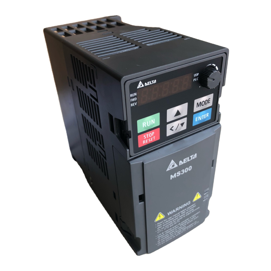
Delta MS300 Series User Manual
Standard compact drive
Hide thumbs
Also See for MS300 Series:
- User manual (805 pages) ,
- Operation manual (56 pages) ,
- Manual (16 pages)

Related Manuals for Delta MS300 Series


Summary of Contents for Delta MS300 Series
- Page 1 CALL NOW 800-985-6929 http://www.deltaacdrives.com Email: info@deltaacdrives.com Delta Standard Compact Drive MS300 Series User Manual CALL NOW 800-985-6929 http://www.deltaacdrives.com Email: info@deltaacdrives.com...
- Page 2 CALL NOW 800-985-6929 http://www.deltaacdrives.com Email: info@deltaacdrives.com PLEASE READ PRIOR TO INSTALLATION FOR SAFETY. AC input power must be disconnected before any wiring to the AC motor drive is made. Even if the power has been turned off, a charge may still remain in the DC-link capacitors with hazardous voltages before the POWER LED is OFF.
-
Page 3: Table Of Contents
CALL NOW 800-985-6929 http://www.deltaacdrives.com Email: info@deltaacdrives.com Table of Contents CHAPTER 1 INTRODUCTION ....................1-1 1-1 Nameplate Information....................1-2 1-2 Model Name.......................1-3 1-3 Serial Number......................1-3 1-4 RFI Jumper........................1-4 CHAPTER 2 DIMENSION ......................2-1 Frame A……………………………………………………..……………………………………2-1 Frame B……………………………………………………………..……………………………2-2 Frame C……………………………………………………………..……………………………2-3 Frame D…………………………………………………………..………………………………2-4 Frame E…………………………………………………………..………………………………2-5 Frame F…………………………………………………………..………………………………2-6 Digital Keypad…………..……………………………………………………………………….2-7 CHAPTER 3 INSTALLATION .................... -
Page 4: Table Of Contents
CALL NOW 800-985-6929 http://www.deltaacdrives.com Email: info@deltaacdrives.com 7-6 EMC Filter.........................7-26 7-7 EMC Shield Plate....................7-30 7-8 Capacitive Filter......................7-33 7-9 Conduit Box…......................7-35 7-10 Fan Kit........................7-43 7-11 Keypad Panel Mounting ……..................7-44 7-12 DIN-Rail Mounting....................7-45 7-13 Mounting Adapter Plate………………………………….……………………………7-47 CHAPTER 8 OPTION CARDS ....................8-1 8-1 Option Card Installation....................8-2 8-2 CMM-MOD01 Modbus/TCP Option Card..............8-7 8-3 CMM-PD01 PROFIBUS Option Card.................8-10... -
Page 5: Table Of Contents
CALL NOW 800-985-6929 http://www.deltaacdrives.com Email: info@deltaacdrives.com 17-3 Wiring Diagram.......................17-4 17-4 Failure Rate of the Drive Safety Function...............17-5 17-5 Reset the Parameter Settings…................17-5 17-6 Timing Diagram Description...................17-6 17-7 Error Code and Troubleshooting Instructions…………………………………………17-9 17-8 Test and Fault Confirmation……………………………………………………….…..17-11 Application Control Board: V 1.0 CALL NOW 800-985-6929 http://www.deltaacdrives.com Email: info@deltaacdrives.com... -
Page 6: Chapter 1 Introduction
CALL NOW 800-985-6929 http://www.deltaacdrives.com Email: info@deltaacdrives.com Chapter 1 IntroductionMS300 Chapter 1 Introduction 1-1 Nameplate Information 1-2 Model Name 1-3 Serial Number 1-4 RFI Jumper CALL NOW 800-985-6929 http://www.deltaacdrives.com Email: info@deltaacdrives.com... -
Page 7: Nameplate Information
CALL NOW 800-985-6929 http://www.deltaacdrives.com Email: info@deltaacdrives.com Chapter 1 Introduction MS300 After receiving the AC motor drive, please check for the following: Please inspect the unit after unpacking to ensure it was not damaged during shipment. Make sure that the part number printed on the package corresponds with the part number indicated on the nameplate. -
Page 8: Model Name
CALL NOW 800-985-6929 http://www.deltaacdrives.com Email: info@deltaacdrives.com Chapter 1 IntroductionMS300 1-2 Model Name 1-3 Serial Number CALL NOW 800-985-6929 http://www.deltaacdrives.com Email: info@deltaacdrives.com... -
Page 9: Rfi Jumper
CALL NOW 800-985-6929 http://www.deltaacdrives.com Email: info@deltaacdrives.com Chapter 1 Introduction MS300 1-4 RFI Jumper (1) In the drive there are Varistor / MOVs, which are connected from phase to phase and from phase to ground, to protect the drive against mains surges or voltage spikes. Because the Varistors / MOVs from phase to ground are connected to ground via the RFI jumper, the protection will be ineffective when the RFI jumper is removed. - Page 10 CALL NOW 800-985-6929 http://www.deltaacdrives.com Email: info@deltaacdrives.com Chapter 1 IntroductionMS300 Isolating main power from ground: When the power distribution system of the drive is a floating ground system (IT) or an asymmetric ground system (TN), the RFI Jumper must be removed. Removing the RFI Jumper disconnects the internal capacitors from ground to avoid damaging the internal circuits and to reduce the ground leakage current.
- Page 11 CALL NOW 800-985-6929 http://www.deltaacdrives.com Email: info@deltaacdrives.com Chapter 1 Introduction MS300 Asymmetric Ground System (Corner Grounded TN Systems) Caution: Do not remove the RFI jumper while the input terminal of the drive carries power. In the following four situations, the RFI jumper must be removed. This is to prevent the system from grounding through the RFI and filter capacitors, damaging the drive.
-
Page 12: Chapter 2 Dimension
CALL NOW 800-985-6929 http://www.deltaacdrives.com Email: info@deltaacdrives.com Chapter 2 Dimensions MS300 Chapter 2 Dimension Frame A A1: VFD1A6MS11ANSAA; VFD1A6MS11ENSAA; VFD1A6MS21ANSAA; VFD1A6MS21ENSAA; VFD1A6MS23ANSAA; VFD1A6MS23ENSAA A2: VFD2A8MS23ANSAA; VFD2A8MS23ENSAA A3: VFD2A5MS11ANSAA; VFD2A5MS11ENSAA; VFD2A8MS21ANSAA; VFD2A8MS21ENSAA A4: VFD1A5MS43ANSAA; VFD1A5MS43ENSAA A5: VFD4A8MS23ANSAA; VFD4A8MS23ENSAA; VFD2A7MS43ANSAA; VFD2A7MS43ENSAA Unit: mm [inch] Frame 68.0 [2.68] 128.0 [5.04]... - Page 13 CALL NOW 800-985-6929 http://www.deltaacdrives.com Email: info@deltaacdrives.com Chapter 2 Dimensions MS300 Frame B B1: VFD7A5MS23ANSAA; VFD7A5MS23ENSAA; VFD4A2MS43ANSAA; VFD4A2MS43ENSAA B2: VFD4A8MS21ANSAA; VFD4A8MS21ENSAA B3: VFD1A6MS21AFSAA; VFD2A8MS21AFSAA; VFD4A8MS21AFSAA; VFD1A5MS43AFSAA; VFD2A7MS43AFSAA; VFD4A2MS43AFSAA Unit: mm [inch] Frame 72.0 [2.83] 142.0 [5.59] 143.0 [5.63] 60.0 [2.36] 130.0 [5.63] 6.4 [0.25] 5.2 [0.20] 72.0 [2.83]...
- Page 14 CALL NOW 800-985-6929 http://www.deltaacdrives.com Email: info@deltaacdrives.com Chapter 2 Dimensions MS300 Frame C C1: VFD4A8MS11ANSAA; VFD4A8MS11ENSAA; VFD7A5MS21ANSAA; VFD7A5MS21ENSAA; VFD11AMS21ANSAA; VFD11AMS21ENSAA; VFD11AMS23ANSAA; VFD11AMS23ENSAA; VFD17AMS23ANSAA; VFD17AMS23ENSAA; VFD5A5MS43ANSAA; VFD5A5MS43ENSAA; VFD9A0MS43ANSAA; VFD9A0MS43ENSAA C2: VFD7A5MS21AFSAA; VFD11AMS21AFSAA; VFD5A5MS43AFSAA; VFD9A0MS43AFSAA Unit: mm [inch] Frame 87.0 [3.43] 157.0 [6.18] 152.0 [5.98] 73.0 [2.87] 144.5 [5.69]...
- Page 15 CALL NOW 800-985-6929 http://www.deltaacdrives.com Email: info@deltaacdrives.com Chapter 2 Dimensions MS300 Frame D D1: VFD25AMS23ANSAA; VFD25AMS23ENSAA; VFD13AMS43ANSAA; VFD13AMS43ENSAA; VFD17AMS43ANSAA; VFD17AMS43ENSAA D2: VFD13AMS43AFSAA; VFD17AMS43AFSAA Unit: mm [inch] Frame 109.0 [4.29] 207.0 [8.15] 154.0 [6.06] 94.0 [3.70] 193.8 [7.63] 6.0 [0.24] 5.5 [0.22] 109.0 [4.29] 207.0 [8.15] 187.0 [7.36]...
- Page 16 CALL NOW 800-985-6929 http://www.deltaacdrives.com Email: info@deltaacdrives.com Chapter 2 Dimensions MS300 Frame E E1: VFD33AMS23ANSAA; VFD33AMS23ENSAA; VFD49AMS23ANSAA; VFD49AMS23ENSAA; VFD25AMS43ANSAA; VFD25AMS43ENSAA; VFD32AMS43ANSAA; VFD32AMS43ENSAA E2: VFD25AMS43AFSAA; VFD32AMS43AFSAA Unit: mm [inch] Frame 130.0 [5.12] 250.0 [9.84] 185.0 [7.83] 115.0 [4.53] 236.8 [9.32] 6.0 [0.24] 5.5 [0.22] 130.0 [5.12] 250.0 [9.84]...
- Page 17 CALL NOW 800-985-6929 http://www.deltaacdrives.com Email: info@deltaacdrives.com Chapter 2 Dimensions MS300 Frame F F1: VFD65AMS23ANSAA; VFD65AMS23ENSAA; VFD38AMS43ANSAA; VFD38AMS43ENSAA; VFD45AMS43ANSAA; VFD45AMS43ENSAA F2: VFD38AMS43AFSAA; VFD45AMS43AFSAA Unit: mm [inch] Frame 175.0 [6.89] 300.0 [11.81] 192.0 [7.56] 154.0 [6.06] 279.5 [11.00] 6.5 [0.26] 8.4 [0.33] 175.0 [6.89] 300.0 [11.81] 244.0 [9.61]...
-
Page 18: Digital Keypad
CALL NOW 800-985-6929 http://www.deltaacdrives.com Email: info@deltaacdrives.com Chapter 2 Dimensions MS300 Digital Keypad KPMS-LE01 Unit: mm [inch] 68.0 [2.67] 63.8 [2.51] 45.2 [1.78] 8.0 [0.31] 46.8 [1.84] 42.0 [1.65] 26.0 [1.02] 7.5 [0.31] 30.0 [1.18] 22.7 [0.89] 2.0 [0.08] 2.2 [0.09] 1.3 [0.05] M3*0.5(2X) CALL NOW 800-985-6929... - Page 19 CALL NOW 800-985-6929 http://www.deltaacdrives.com Email: info@deltaacdrives.com Chapter 2 Dimensions MS300 [ This page intentionally left blank ] CALL NOW 800-985-6929 http://www.deltaacdrives.com Email: info@deltaacdrives.com...
-
Page 20: Chapter 3 Installation
CALL NOW 800-985-6929 http://www.deltaacdrives.com Email: info@deltaacdrives.com Chapter 3 Installation MS300 Chapter 3 Installation Minimum Mounting Clearance and Installation Prevent fiber particles, scraps of paper, shredded wood saw dust, metal particles, etc. from adhering to the heat sink Install the AC motor drive in a metal cabinet. When installing one drive below another one, use a ... - Page 21 CALL NOW 800-985-6929 http://www.deltaacdrives.com Email: info@deltaacdrives.com Chapter 3 Installation MS300 Air flow rate for cooling Power Dissipation Frame Flow Rate Flow Rate Loss External Internal Total Model No. (Unit: cfm) (Unit: m / hr) (Heat sink, unit: W) (Unit: W) (Unit: W) VFD1A6MS11ANSAA 10.0...
- Page 22 CALL NOW 800-985-6929 http://www.deltaacdrives.com Email: info@deltaacdrives.com Chapter 3 Installation MS300 Air flow rate for cooling Power Dissipation Frame Flow Rate Flow Rate Loss External Internal Total Model No. (Unit: cfm) (Unit: m / hr) (Heat sink, unit: W) (Unit: W) (Unit: W) VFD9A0MS43ENSAA VFD9A0MS43AFSAA...
- Page 23 CALL NOW 800-985-6929 http://www.deltaacdrives.com Email: info@deltaacdrives.com Chapter 3 Installation MS300 [ This page intentionally left blank ] CALL NOW 800-985-6929 http://www.deltaacdrives.com Email: info@deltaacdrives.com...
-
Page 24: Chapter 4 Wiring
CALL NOW 800-985-6929 http://www.deltaacdrives.com Email: info@deltaacdrives.com Chapter 4 WiringMS300 Chapter 4 Wiring 4-1 Wiring 4-2 System Wiring Diagram CALL NOW 800-985-6929 http://www.deltaacdrives.com Email: info@deltaacdrives.com... - Page 25 CALL NOW 800-985-6929 http://www.deltaacdrives.com Email: info@deltaacdrives.com Chapter 4 WiringMS300 After removing the front cover, please check if the power and control terminals are clearly visible. Please read following precautions to avoid wiring mistakes. It is crucial to cut off the AC motor drive power before doing any wiring. A charge may still remain in the DC bus capacitors with hazardous voltages even after the power has been turned off a short time.
-
Page 26: Wiring
CALL NOW 800-985-6929 http://www.deltaacdrives.com Email: info@deltaacdrives.com Chapter 4 WiringMS300 4-1 Wiring CALL NOW 800-985-6929 http://www.deltaacdrives.com Email: info@deltaacdrives.com... - Page 27 CALL NOW 800-985-6929 http://www.deltaacdrives.com Email: info@deltaacdrives.com Chapter 4 WiringMS300 Figure 1 CALL NOW 800-985-6929 http://www.deltaacdrives.com Email: info@deltaacdrives.com...
- Page 28 CALL NOW 800-985-6929 http://www.deltaacdrives.com Email: info@deltaacdrives.com Chapter 4 WiringMS300 Figure 2 SINK (NPN) / SOURCE (PNP) Mode S i n k Mo d e S o u r ce Mo d e wi th i n te r n a l p o we r ( +2 4 V d c) wi th i n te r n a l p o we r ( +2 4 V d c) i n te rn a l i n te rn a l...
-
Page 29: System Wiring Diagram
CALL NOW 800-985-6929 http://www.deltaacdrives.com Email: info@deltaacdrives.com Chapter 4 WiringMS300 4-2 System Wiring Diagram CALL NOW 800-985-6929 http://www.deltaacdrives.com Email: info@deltaacdrives.com... -
Page 30: Chapter 5 Main Circuit Terminals
CALL NOW 800-985-6929 http://www.deltaacdrives.com Email: info@deltaacdrives.com Chapter 5 Main Circuit TerminalsMS300 Chapter 5 Main Circuit Terminals 5-1 Main Circuit Diagram 5-2 Main Circuit Terminals CALL NOW 800-985-6929 http://www.deltaacdrives.com Email: info@deltaacdrives.com... - Page 31 U/T1, V/T2, W/T3 of the AC motor drive. DO NOT use phase-compensation DANGER capacitors or L-C (Inductance-Capacitance) or R-C (Resistance-Capacitance), unless approved by Delta. DO NOT connect brake resistor directly to +1/DC+ to DC-, +2/B1 to DC- to prevent damage to the drive.
-
Page 32: Remove The Front Cover
CALL NOW 800-985-6929 http://www.deltaacdrives.com Email: info@deltaacdrives.com Chapter 5 Main Circuit TerminalsMS300 Terminals for connecting DC reactor, external brake resistor and DC circuit These are the terminals for connecting the DC-reactor to improve the power factor and harmonics. At delivery they are shorted by a jumper. Please remove it before connecting the DC reactor. -
Page 33: Main Circuit Diagram
CALL NOW 800-985-6929 http://www.deltaacdrives.com Email: info@deltaacdrives.com Chapter 5 Main Circuit TerminalsMS300 5-1 Main Circuit Diagram Terminals Descriptions R/L1, S/L2 Mains input terminals 1-phase R/L1, S/L2, T/L3 Mains input terminals 3-phase U/T1, V/T2, W/T3 Motor output terminals for connecting 3-phase IM and PM motors. Connections for DC reactor to improve the power factor and harmonics. -
Page 34: Main Circuit Terminals
CALL NOW 800-985-6929 http://www.deltaacdrives.com Email: info@deltaacdrives.com Chapter 5 Main Circuit TerminalsMS300 5-2 Main Circuit Terminals It needs following additional terminal when wiring. The additional terminal dimension should comply with the following figure 1. After crimping the wire to the ring lug (must UL approved), UL and CSA approved R/C (YDPU2) heat shrink tubing rated min 600Vac insulation shall be install over the live part. - Page 35 CALL NOW 800-985-6929 http://www.deltaacdrives.com Email: info@deltaacdrives.com Chapter 5 Main Circuit TerminalsMS300 Frame A Main circuit terminals: R/L1, S/L2, T/L3, U/T1, V/T2, W/T3, ,DC-, DC+/+1, +2/B1, B2, Note: 1-phase model with no T/L3 terminal Max. Min. Wire Torque Models Wire Screw Gauge (±10%) Gauge...
- Page 36 CALL NOW 800-985-6929 http://www.deltaacdrives.com Email: info@deltaacdrives.com Chapter 5 Main Circuit TerminalsMS300 Frame B Main circuit terminals: R/L1, S/L2, T/L3, U/T1, V/T2, W/T3, ,DC-, DC+/+1, +2/B1, B2, Note: 1-phase model with no T/L3 terminal Max. Wire Min. Wire Torque Models Screw Gauge Gauge (±10%)
- Page 37 CALL NOW 800-985-6929 http://www.deltaacdrives.com Email: info@deltaacdrives.com Chapter 5 Main Circuit TerminalsMS300 Frame C Main circuit terminals: R/L1, S/L2, T/L3, U/T1, V/T2, W/T3, ,DC-, DC+/+1, +2/B1, B2, Note: 1-phase model with no T/L3 terminal Max. Wire Min. Wire Torque Models Screw Gauge Gauge (±10%)
- Page 38 CALL NOW 800-985-6929 http://www.deltaacdrives.com Email: info@deltaacdrives.com Chapter 5 Main Circuit TerminalsMS300 Frame D Main circuit terminals: R/L1, S/L2, T/L3, U/T1, V/T2, W/T3, , DC-, DC+/+1, +2/B1, B2, Max. Wire Min. Wire Torque Models Screw Gauge Gauge (±10%) VFD25AMS23ANSAA 8 AWG [8.4mm VFD25AMS23ENSAA VFD13AMS43ANSAA...
- Page 39 CALL NOW 800-985-6929 http://www.deltaacdrives.com Email: info@deltaacdrives.com Chapter 5 Main Circuit TerminalsMS300 Frame E Main circuit terminals: R/L1, S/L2, T/L3, U/T1, V/T2, W/T3, , DC-, DC+/+1, +2/B1, B2, Max. Wire Min. Wire Torque Models Screw Gauge Gauge (±10%) VFD33AMS23ANSAA 6 AWG 6 AWG VFD33AMS23ENSAA [13.3 mm...
- Page 40 CALL NOW 800-985-6929 http://www.deltaacdrives.com Email: info@deltaacdrives.com Chapter 5 Main Circuit TerminalsMS300 Frame F Main circuit terminals: R/L1, S/L2, T/L3, U/T1, V/T2, W/T3, , DC-, DC+/+1, +2/B1, B2, Max. Wire Min. Wire Torque Models Screw Gauge Gauge (±10%) VFD65AMS23ANSAA 2 AWG [33.6 mm VFD65AMS23ENSAA VFD38AMS43ANSAA...
- Page 41 CALL NOW 800-985-6929 http://www.deltaacdrives.com Email: info@deltaacdrives.com Chapter 5 Main Circuit TerminalsMS300 [ This page intentionally left blank ] 5-12 CALL NOW 800-985-6929 http://www.deltaacdrives.com Email: info@deltaacdrives.com...
- Page 42 CALL NOW 800-985-6929 http://www.deltaacdrives.com Email: info@deltaacdrives.com Chapter 6 Control TerminalsMS300 Chapter 6 Control Terminals Analog input terminals (AVI, ACI, ACM) Analog input signals are easily affected by external noise. Use shielded wiring and keep it as short as possible (<20 m) with proper grounding. If the noise is inductive, connecting the shield to terminal ACM can bring improvement.
- Page 43 CALL NOW 800-985-6929 http://www.deltaacdrives.com Email: info@deltaacdrives.com Chapter 6 Control TerminalsMS300 Specifications of Control Terminal Specifications of RELAY Terminal Wire Gauge: 20~18AWG [0.519~0.82 mm Wire Gauge: 24~16 AWG [0.205~1.3 mm Torque: 5 kg-cm / [4.3 Ib-in.] / [0.49 Nm] DATAMATRIX Safety function 32637012 RELAY RS485...
- Page 44 CALL NOW 800-985-6929 http://www.deltaacdrives.com Email: info@deltaacdrives.com Chapter 6 Control TerminalsMS300 Terminals Terminal Function Factory Setting (NPN mode) Digital control signal common +24V +24V ± 10 % 100 mA (Source) Refer to parameters 02-01~02-07 to program the multi-function inputs MI1~MI7. Source Mode ON: the activation current is 3.3 mA ≧...
- Page 45 CALL NOW 800-985-6929 http://www.deltaacdrives.com Email: info@deltaacdrives.com Chapter 6 Control TerminalsMS300 Terminals Terminal Function Factory Setting (NPN mode) +10V Potentiometer power supply +10.5 ± 0.5 Vdc / 20 mA Analog voltage input Programmable analog input, see Pr. 03-00 Impedance: 20kΩ internal circuit Range 0~Max.
- Page 46 CALL NOW 800-985-6929 http://www.deltaacdrives.com Email: info@deltaacdrives.com Chapter 6 Control TerminalsMS300 Terminals Terminal Function Factory Setting (NPN mode) Factory setting: S1/S2 shorted to +24V Rated voltage: 24VDC ±10%; Max. voltage: 30VDC ±10% S1,S2 Activation current: 6.67 mA ±10% STO activation mode Input voltage level: S1-DCM>0VDC or S2-DCM <...
- Page 47 CALL NOW 800-985-6929 http://www.deltaacdrives.com Email: info@deltaacdrives.com Chapter 6 Control TerminalsMS300 [ This page intentionally left blank ] CALL NOW 800-985-6929 http://www.deltaacdrives.com Email: info@deltaacdrives.com...
-
Page 48: Chapter 7 Optional Accessories
CALL NOW 800-985-6929 http://www.deltaacdrives.com Email: info@deltaacdrives.com Chapter 7 Optional AccessoriesMS300 Chapter 7 Optional Accessories All Brake Resistors and Brake Units Used in AC Motor Drives Non-fuse Circuit Breaker Fuse Specification Chart AC/DC Reactor Zero Phase Reactor EMC Filter EMC Shield Plate Capacitive Filter Conduit Box 7-10 Fan Kit... -
Page 49: All Brake Resistors And Brake Units Used In Ac Motor Drives
CALL NOW 800-985-6929 http://www.deltaacdrives.com Email: info@deltaacdrives.com Chapter 7 Optional Accessories MS300 The optional accessories listed in this chapter are available upon request. Installing additional accessories to your drive would substantially improve the drive’s performance. Please select an applicable accessory according to your need or contact the local distributor for suggestion. 7-1 All Brake Resistors and Brake Units Used in AC Motor Drives 115V 1-phase Applicable... - Page 50 Resistors of 1000W and above should be fixed on a surface with temperature below 350°C NOTE Please select the resistance value, power and brake usage (ED %) acc. to Delta rules. Definition for Brake Usage ED% Explanation: ED (%) is defined to allow enough time for the brake unit and brake resistor to dissipate the heat generated by braking.
- Page 51 CALL NOW 800-985-6929 http://www.deltaacdrives.com Email: info@deltaacdrives.com Chapter 7 Optional Accessories MS300 Take the safety of the environment into consideration when installing the brake resistors. If the minimum resistance value is to be used, consult local dealers for the calculation of the power. When using more than 2 brake units, equivalent resistor value of parallel brake unit can’t be less than the value in the column “Minimum Equivalent Resistor Value for Each AC Drive”...
-
Page 52: Non-Fuse Circuit Breaker
CALL NOW 800-985-6929 http://www.deltaacdrives.com Email: info@deltaacdrives.com Chapter 7 Optional AccessoriesMS300 7-2 Non-fuse Circuit Breaker Comply with UL standard: Per UL 508, paragraph 45.8.4, part a. Current Input / Output (Max.) Breaker rating Input (A) Voltage / 1-phase Model (3-phase) Normal duty Heavy duty Normal duty Heavy duty... - Page 53 CALL NOW 800-985-6929 http://www.deltaacdrives.com Email: info@deltaacdrives.com Chapter 7 Optional Accessories MS300 Current Input / Output (Max.) Breaker rating Input (A) Voltage / 1-phase Model (3-phase) Normal duty Heavy duty Normal duty Heavy duty VFD2A7MS43ANSXX 4.2 A / 3.0 A 3.7 A / 2.7 A 8.58 VFD2A7MS43ENSXX...
-
Page 54: Fuse Specification Chart
CALL NOW 800-985-6929 http://www.deltaacdrives.com Email: info@deltaacdrives.com Chapter 7 Optional AccessoriesMS300 7-3 Fuse Specification Chart The fuse specifications lower than below table is allowed. For installation in the United States, branch circuit protection must be provided in accordance with the National Electrical Code (NEC) and any applicable local codes. To fulfill this requirement, use the UL classified fuses. - Page 55 CALL NOW 800-985-6929 http://www.deltaacdrives.com Email: info@deltaacdrives.com Chapter 7 Optional Accessories MS300 Current Input / Output (Max.) Voltage/ 1-phase Branch Circuit Fuses Output Model (3-phase) Normal duty Heavy duty 79.2 VFD33AMS23ANSXX 43.2 A / 36.0 A 39.6 A / 33.0 A VFD33AMS23ENSXX Class T JJS-80 112.2...
-
Page 56: Ac/Dc Reactor
Saturation Rated Current Input/ Output Input Reactor DC Reactor DC Reactor Model ND / HD ND / HD (A Reactor (mH) Delta Part # (mH) Delta Part # Current (A VFD1A6MS11ANSAA 1.8 / 1.6 2.7 / 3.2 5.857 DR005D0585 5.857... - Page 57 Saturation Rated Current Input/ Output Input Reactor DC Reactor DC Reactor Model ND / HD ND / HD (A Reactor (mH) Delta Part # (mH) Delta Part # Current (A VFD4A8MS21ANSAA 5 / 4.8 7.5 / 9.6 3.66 DR008D0366 3.66...
- Page 58 Rated Saturation Current Input/ Output Input Reactor DC Reactor DC Reactor Model ND / HD ND / HD Reactor (mH) Delta Part # (mH) Delta Part # Current (A VFD2A7MS43ANSAA 3 / 2.7 4.5 / 5.4 6.077 DR004A0607 18.709 DR003D1870...
- Page 59 Screw Location Torque Terminal 5.32~7.09 kg-cm / [6.12~8.16 lb-in.] / [0.6~0.8 Nm] PE bolt 8.86~10.63 kg-cm / [10.2~12.24 lb-in.] / [1.0~1.2 Nm] Input AC reactor D1*D2 PE D Delta part # DR005A0254 DR008A0159 6*12 80.5 DR011A0115 6*12 80.5 DR017AP746 6*12 80.5...
- Page 60 Email: info@deltaacdrives.com Chapter 7 Optional AccessoriesMS300 Screw Location Torque Terminal 10.63~12.4 kg-cm / [12.24~14.28 lb-in.] / [1.2~1.4 Nm] Input AC reactor D1*D2 PE D Delta part # DR049AP215 6*12 1.2~1.4 DR065AP163 6*12 2.5~3.0 Unit:mm 7-13 CALL NOW 800-985-6929 http://www.deltaacdrives.com...
- Page 61 CALL NOW 800-985-6929 http://www.deltaacdrives.com Email: info@deltaacdrives.com Chapter 7 Optional Accessories MS300 Input AC reactor D1*D2 Delta part # DR075AP170 7*13 20*3 Unit:mm 7-14 CALL NOW 800-985-6929 http://www.deltaacdrives.com Email: info@deltaacdrives.com...
- Page 62 Screw Location Torque Terminal 5.32~7.09 kg-cm / [6.12~8.16 lb-in.] / [0.6~0.8 Nm] PE bolt 8.86~10.63 kg-cm / [10.2~12.24 lb-in.] / [1.0~1.2 Nm] Input AC reactor D1*D2 PE D Delta part # DR003A0810 DR004A0607 6*12 80.5 DR006A0405 6*12 DR009A0270 6*12 DR010A0231...
- Page 63 Email: info@deltaacdrives.com Chapter 7 Optional Accessories MS300 Screw Location Torque Terminal 10.63~12.4 kg-cm / [12.24~14.28 lb-in.] / [1.2~1.4 Nm] Input AC reactor D1*D2 PE D Delta part # DR038AP639 6*12 1.2~1.4 DR045AP541 7*13 1.2~1.4 Unit:mm 7-16 CALL NOW 800-985-6929 http://www.deltaacdrives.com...
- Page 64 CALL NOW 800-985-6929 http://www.deltaacdrives.com Email: info@deltaacdrives.com Chapter 7 Optional AccessoriesMS300 Input AC reactor D1*D2 Delta part # DR060AP405 7*13 20*3 Unit:mm 7-17 CALL NOW 800-985-6929 http://www.deltaacdrives.com Email: info@deltaacdrives.com...
- Page 65 CALL NOW 800-985-6929 http://www.deltaacdrives.com Email: info@deltaacdrives.com Chapter 7 Optional Accessories MS300 DC reactor can also, improve power factor, reduce input current, and reduce interference generated from motor drive. A DC reactor stabilizes the DC-bus voltage. Compared to an AC input reactor, the advantages are smaller size, lower price and lower voltage drop (lower power dissipation) Installation DC reactor is installed between terminals +1 and +2.
- Page 66 Chapter 7 Optional AccessoriesMS300 DC reactor dimension and specification: The length of screw should keep away from the hole. DC reactor Rated Current Saturation current DC reactor Dimension Delta Part # (Arms) (Arms) (mH) (mm) (mm) (mm) (mm) (mm) (mm) DR005D0585 8.64...
- Page 67 CALL NOW 800-985-6929 http://www.deltaacdrives.com Email: info@deltaacdrives.com Chapter 7 Optional Accessories MS300 DC reactor Rated Current Saturation current DC reactor Dimension Delta Part # (Arms) (Arms) (mH) (mm) (mm) (mm) (mm) (mm) (mm) DR012D0467 19.8 4.677 119 128 DR018D0311 30.6 3.119...
- Page 68 CALL NOW 800-985-6929 http://www.deltaacdrives.com Email: info@deltaacdrives.com Chapter 7 Optional AccessoriesMS300 Without AC reactor With AC reactor 230V 1-phase Rated current Shielded Cable Non-shielded Shielded Cable Non-shielded (ND) (Arms) Model (meter) cable (meter) (meter) cable (meter) VFD1A6MS21ANSAA VFD1A6MS21ENSAA VFD1A6MS21AFSAA VFD2A8MS21ANSAA VFD2A8MS21ENSAA VFD2A8MS21AFSAA VFD4A8MS21ANSAA VFD4A8MS21ENSAA...
- Page 69 CALL NOW 800-985-6929 http://www.deltaacdrives.com Email: info@deltaacdrives.com Chapter 7 Optional Accessories MS300 Without AC reactor With AC reactor 460V 3-phase Rated current Shielded Cable Non-shielded Shielded Cable Non-shielded (ND) (Arms) Model (meter) cable (meter) (meter) cable (meter) VFD1A5MS43ANSAA VFD1A5MS43ENSAA VFD1A5MS43AFSAA VFD2A7MS43ANSAA VFD2A7MS43ENSAA VFD2A7MS43AFSAA...
-
Page 70: Zero Phase Reactor
Interferences can also be suppressed by installing a zero phase reactor at the mains input or the motor output of the drive, depending on where the interference is. Delta provides two types of zero phase reactors to solve interference problems. - Page 71 CALL NOW 800-985-6929 http://www.deltaacdrives.com Email: info@deltaacdrives.com Chapter 7 Optional Accessories MS300 Installation During installation, please pass the cable through at least one zero-phase reactor. Use a suitable cable type (insulation class and wire section) so that the cable passes easily through the zero-phase reactor.
- Page 72 CALL NOW 800-985-6929 http://www.deltaacdrives.com Email: info@deltaacdrives.com Chapter 7 Optional AccessoriesMS300 Recommended max. wiring gauge when installing zero phase reactor Max. Wire Gauge AWG Max. Wire Gauge AWG Model # of Zero Max, Wire Gauge (1Cx3) (1Cx4) Phase Reactor or LUG width 75 °C 90 °C 75 °C...
-
Page 73: Emc Filter
Recommended model of cable length Input zero-phase reactor Frame Model # Current Filter model # 100m 100m Position to place zero phase reactor DELTA VFD1A6MS11ANSAA EMF11AM21A RF008X00A T60006L2040W453 VFD1A6MS21ANSAA EMF11AM21A RF008X00A T60006L2040W453 ✓ ✓ ✓ ✓ VFD2A8MS21ANSAA EMF11AM21A RF008X00A T60006L2040W453 ✓... - Page 74 CALL NOW 800-985-6929 http://www.deltaacdrives.com Email: info@deltaacdrives.com Chapter 7 Optional AccessoriesMS300 Filter Dimension EMF11AM21A EMF10AM23A EMF6A0M43A Screw Torque M5 * 2 16~20 kg-cm / [13.9~17.3 lb-in.] / [1.56~1.96 Nm] M4 * 2 14~16 kg-cm / [12.2~13.8 lb-in.] / [1.38~1.56 Nm] 72.0 [2.83] M5 screw TORQUE:16-18kgf-cm 54.0 [2.13]...
- Page 75 CALL NOW 800-985-6929 http://www.deltaacdrives.com Email: info@deltaacdrives.com Chapter 7 Optional Accessories MS300 EMF27AM21B; EMF24AM23B EMF33AM23B; EMF12AM43B EMF23AM43B Screw Torque M5 * 4 16~20 kg-cm / [13.9~17.3 lb-in.] / [1.56~1.96 Nm] 109.0 [4.29] M5 screw 94.0 [3.70] TORQUE:16-18kgf-cm 76.0 [2.99] 28.0 [1.10] 29.1 [1.14] 5.5 [0.22] 5.5 [0.22]...
- Page 76 CALL NOW 800-985-6929 http://www.deltaacdrives.com Email: info@deltaacdrives.com Chapter 7 Optional AccessoriesMS300 TDK B84143D0050R127 (50A) TDK B84143D0075R127 (75A), TDK B84143D0090R127 (90A) 7-29 CALL NOW 800-985-6929 http://www.deltaacdrives.com Email: info@deltaacdrives.com...
-
Page 77: Emc Shield Plate
CALL NOW 800-985-6929 http://www.deltaacdrives.com Email: info@deltaacdrives.com Chapter 7 Optional Accessories MS300 7-7 EMC Shield Plate EMC Shield Plate (for use with use shielded cable) EMC Shield Plate model Reference figure Frame MKM-EPA MKM-EPB MKM-EPC MKM-EPD MKM-EPE MKM-EPF 7-30 CALL NOW 800-985-6929 http://www.deltaacdrives.com Email: info@deltaacdrives.com... - Page 78 CALL NOW 800-985-6929 http://www.deltaacdrives.com Email: info@deltaacdrives.com Chapter 7 Optional AccessoriesMS300 Installation (Frame A model as an example) 1. As on the right, fix the iron plate on the AC motor drive. Torque value: Frame Screw Torque M3.5 6~8 kg-cm / [5.2~6.9 lb-in.] / [0.59~0.78 Nm] 6~8 kg-cm / [5.2~6.9 lb-in.] / [0.59~0.78 Nm] 6~8 kg-cm / [5.2~6.9 lb-in.] / [0.59~0.78 Nm] 4~6 kg-cm / [3.5~5.2 lb-in.] / [0.39~0.59 Nm]...
- Page 79 CALL NOW 800-985-6929 http://www.deltaacdrives.com Email: info@deltaacdrives.com Chapter 7 Optional Accessories MS300 Recommended wire mounting method Frame Model of EMC Shield Plate Reference figure MKM-EPA MKM-EPB MKM-EPC MKM-EPD MKM-EPE MKM-EPF 7-32 CALL NOW 800-985-6929 http://www.deltaacdrives.com Email: info@deltaacdrives.com...
-
Page 80: Capacitive Filter
CALL NOW 800-985-6929 http://www.deltaacdrives.com Email: info@deltaacdrives.com Chapter 7 Optional AccessoriesMS300 7-8 Capacitive Filter diagram Installation The capacitive filter (CXY101-43A) is a simple filter which can support basic filtering and noise interference reduction. Capacitor Filter Grid Motor Capacitive filter and drive wiring figure: R/L1 S/L2 T/ L3 Specification:... - Page 81 CALL NOW 800-985-6929 http://www.deltaacdrives.com Email: info@deltaacdrives.com Chapter 7 Optional Accessories MS300 Dimension: CXY101-43A Unit:mm [inch] 77 .5 [3 .05 ] 77 .5 [3 .05 ] 86 .5 [3 .41 ] 4.0 [ 0.1 6] 31 .6 [1 .24 ] 7-34 CALL NOW 800-985-6929 http://www.deltaacdrives.com...
-
Page 82: Conduit Box
CALL NOW 800-985-6929 http://www.deltaacdrives.com Email: info@deltaacdrives.com Chapter 7 Optional AccessoriesMS300 7-9 Conduit Box Conduit box are in compliance with protection level NEMA 1 / UL Type 1 Frame A (A1~A2) Frame A (A3~A5) Model of conduit box: MKM-CBA0 Model of conduit box: MKM-CBA 71 5 2 81 . - Page 83 CALL NOW 800-985-6929 http://www.deltaacdrives.com Email: info@deltaacdrives.com Chapter 7 Optional Accessories MS300 Frame B Model of conduit box: MKM-CBB 87 7 3 45 . [ . 71 9 2 83 . [ . Unit : mm [inch.] 7-36 CALL NOW 800-985-6929 http://www.deltaacdrives.com Email: info@deltaacdrives.com...
- Page 84 CALL NOW 800-985-6929 http://www.deltaacdrives.com Email: info@deltaacdrives.com Chapter 7 Optional AccessoriesMS300 Frame C Model of conduit box: MKM-CBC 89 2 3 51 . [ . 87 0 3 43 . [ . Unit : mm [inch.] 7-37 CALL NOW 800-985-6929 http://www.deltaacdrives.com Email: info@deltaacdrives.com...
- Page 85 CALL NOW 800-985-6929 http://www.deltaacdrives.com Email: info@deltaacdrives.com Chapter 7 Optional Accessories MS300 Frame D Model of conduit box: MKM-CBD 8 8 5 3 48 . [ . 103 7 4 08 . [ . Unit mm inch Unit : mm [inch.] 7-38 CALL NOW 800-985-6929 http://www.deltaacdrives.com...
- Page 86 CALL NOW 800-985-6929 http://www.deltaacdrives.com Email: info@deltaacdrives.com Chapter 7 Optional AccessoriesMS300 Frame E Model of conduit box: MKM-CBE 8 7 1 3 43 . [ . 1 24 5 4 90 . [ . Unit m m inch Unit : mm [inch.] 7-39 CALL NOW 800-985-6929 http://www.deltaacdrives.com...
- Page 87 CALL NOW 800-985-6929 http://www.deltaacdrives.com Email: info@deltaacdrives.com Chapter 7 Optional Accessories MS300 Frame F Model of conduit box: MKM-CBF 168 7 6 64 . [ . 90 8 3 57 . [ . Unit : mm [inch.] 7-40 CALL NOW 800-985-6929 http://www.deltaacdrives.com Email: info@deltaacdrives.com...
- Page 88 CALL NOW 800-985-6929 http://www.deltaacdrives.com Email: info@deltaacdrives.com Chapter 7 Optional AccessoriesMS300 Installation: Recommended screw torque: M3: 4-6 kg-cm / [3.5-5.2 lb-in.] / [0.39-0.59 Nm] M3.5: 4-6 kg-cm / [3.5-5.2 lb-in.] / [0.39-0.59 Nm] M4: 6-8 kg-cm / [5.2-6.9 lb-in.] / [0.59-0.78 Nm] Frame A 7-41 CALL NOW 800-985-6929...
- Page 89 CALL NOW 800-985-6929 http://www.deltaacdrives.com Email: info@deltaacdrives.com Chapter 7 Optional Accessories MS300 Frame B~F 7-42 CALL NOW 800-985-6929 http://www.deltaacdrives.com Email: info@deltaacdrives.com...
-
Page 90: Fan Kit
CALL NOW 800-985-6929 http://www.deltaacdrives.com Email: info@deltaacdrives.com Chapter 7 Optional AccessoriesMS300 7-10 Fan Kit Frame Fan Model Fan Kit MKM-FKMA MKM-FKMB MKM-FKMC MKM-FKMD MKM-FKME MKM-FKMF Fan Removal 1. As shown in figure on the right, press the tabs on both sides of the fan to remove it. 2. -
Page 91: Keypad Panel Mounting
CALL NOW 800-985-6929 http://www.deltaacdrives.com Email: info@deltaacdrives.com Chapter 7 Optional Accessories MS300 7-11 Keypad Panel Mounting KPMS-LE01 Method 1: Direct installation on a plate (unit: mm [inch]) Torque: 8~9 kg-cm [6.94~7.81 lb-in.] [0.78~0.88 Nm] Method 2: Mounting through a plate (unit: mm [inch]) Thickness = 1.2 [0.05] or 2.0 [0.08] ※... -
Page 92: Din-Rail Mounting
CALL NOW 800-985-6929 http://www.deltaacdrives.com Email: info@deltaacdrives.com Chapter 7 Optional AccessoriesMS300 7-12 DIN-Rail Mounting MKM-DRB (applicable for Frame A and Frame B) 72.0[2.83] 8.0[0.31] Screw Torque 8~10 kg-cm M4*2PCS [6.9~8.7 lb-in.] [0.7 ~0 98 Nm] 4.6[0.18] (M4 NUT) unit: mm[inch] MKM-DRC (applicable for Frame C) Screw Torque 87.0[3.43]... - Page 93 CALL NOW 800-985-6929 http://www.deltaacdrives.com Email: info@deltaacdrives.com Chapter 7 Optional Accessories MS300 Installation Screw Torque 8~10 kg-cm MKM-DRB M4*P0.7*2PCS [6.9~8.7 lb-in.] [0.78~0.98 Nm] 10~12 kg-cm MKM-DRC M5*P0.8*4PCS [8.7~10.4 lb-in.] [0.98~1.18 Nm] MKM-DRB: for frame A. B MKM-DRC: for frame C 7-46 CALL NOW 800-985-6929 http://www.deltaacdrives.com...
-
Page 94: Mounting Adapter Plate
CALL NOW 800-985-6929 http://www.deltaacdrives.com Email: info@deltaacdrives.com Chapter 7 Optional AccessoriesMS300 7-13 Mounting Adapter Plate This mounting adapter accessory is to change the wiring way of MS300/MH300 series to provide flexible installation. It changes the wiring from mains input/motor output at the bottom to mains input from the top and motor output from the bottom. - Page 95 CALL NOW 800-985-6929 http://www.deltaacdrives.com Email: info@deltaacdrives.com Chapter 7 Optional Accessories MS300 MKM-MAPB: Applicable for Frame A and B Installation L 1 L 2 L 3 Unit: mm [inch] Screw Torque 14~16 kg-cm / [12.2~13.9 lb-in.] / [1.37~1.56 Nm] 16~20 kg-cm / [13.9~17.4 lb-in.] / [1.56~1.96 Nm] 7-48 CALL NOW 800-985-6929 http://www.deltaacdrives.com...
- Page 96 CALL NOW 800-985-6929 http://www.deltaacdrives.com Email: info@deltaacdrives.com Chapter 7 Optional AccessoriesMS300 MKM-MAPC: Applicable for frame C Installation Unit: mm [inch] Screw Torque 14~16 kg-cm / [12.2~13.9 lb-in.] / [1.37~1.56 Nm] 16~20 kg-cm / [13.9~17.4 lb-in.] / [1.56~1.96 Nm] 7-49 CALL NOW 800-985-6929 http://www.deltaacdrives.com Email: info@deltaacdrives.com...
- Page 97 CALL NOW 800-985-6929 http://www.deltaacdrives.com Email: info@deltaacdrives.com Chapter 7 Optional Accessories MS300 [ This page intentionally left blank ] 7-50 CALL NOW 800-985-6929 http://www.deltaacdrives.com Email: info@deltaacdrives.com...
-
Page 98: Chapter 8 Option Cards
CALL NOW 800-985-6929 http://www.deltaacdrives.com Email: info@deltaacdrives.com Chapter 8 Optional Cards MS300 Chapter 8 Option Cards Option Card Installation CMM-MOD01 Modbus/TCP option card CMM-PD01 PROFIBUS option card CMM-DN01 DeviceNet option card CMM-EIP01 Modbus TCP/EtherNet IP option card CMM-COP01 CANopen option card EMM-BPS01 Back-up Power Supply card CALL NOW 800-985-6929 http://www.deltaacdrives.com... -
Page 99: Option Card Installation
CALL NOW 800-985-6929 http://www.deltaacdrives.com Email: info@deltaacdrives.com Chapter 8 Optional Cards MS300 The option cards mentioned in this chapter are optional items. Please select applicable option cards for your drive or contact your local distributor for suggestion. The option cards can improve the performance of the drive significantly. - Page 100 CALL NOW 800-985-6929 http://www.deltaacdrives.com Email: info@deltaacdrives.com Chapter 8 Optional Cards MS300 NOTE Wiring after the option card fixed fitting is clipped with the holes (see Fasten the screw to fix the option card before wiring (shown in Fig. 8-3). Torque:4~6 kg-cm [3.5~5.2 lb-in] / [0.39~0.59 Nm].
- Page 101 CALL NOW 800-985-6929 http://www.deltaacdrives.com Email: info@deltaacdrives.com Chapter 8 Optional Cards MS300 Fasten the screw after the option card fixed fitting is clipped with the holes. (shown in Fig. 8-5) Torque: 4~6 kg-cm [3.5~5.2 lb-in.] [0.39~0.59 Nm] Fig. 8-5 Installation is completed (shown in Fig. 8-6). Put the front cover back on. Fig.
- Page 102 CALL NOW 800-985-6929 http://www.deltaacdrives.com Email: info@deltaacdrives.com Chapter 8 Optional Cards MS300 NOTE The option cards listed below must connect to ground when wiring. The ground terminal is enclosed with option card as shown in Fig. 8-7. 1. CMM-MOD01 2. CMM-PD01 3.
- Page 103 CALL NOW 800-985-6929 http://www.deltaacdrives.com Email: info@deltaacdrives.com Chapter 8 Optional Cards MS300 Frame F Fig. 8-11 Torque (±10%) Frame F: 7 kg-cm [6.1 Ib-in.] [0.69 Nm] CALL NOW 800-985-6929 http://www.deltaacdrives.com Email: info@deltaacdrives.com...
-
Page 104: Cmm-Mod01 Modbus/Tcp Option Card
Category 5e shielding 100 M Transmission speed 10 / 100 Mbps Auto-Detect Network protocol ICMP, IP, TCP, UDP, DHCP, SMTP, MODBUS OVER TCP / IP, Delta Configuration Electrical Specification Power supply voltage 5 VDC (supplied by AC motor drive) Insulation voltage... - Page 105 Setting for source of The operation command is controlled by 00-21 communication card operation command Decoding method for 09-30 Decoding method for Delta AC motor drive communication 09-75 IP setting Static IP(0) / Dynamic distribution IP(1) 09-76 IP address -1 IP address 192.168.1.5...
- Page 106 CALL NOW 800-985-6929 http://www.deltaacdrives.com Email: info@deltaacdrives.com Chapter 8 Optional Cards MS300 LED Indicator & Troubleshooting LED Indicators Status Indication Processing Methods POWER Green Power supply in normal status No action is required POWER Green No power supply Check the power supply Network connection in normal No action is required status...
-
Page 107: Cmm-Pd01 Profibus Option Card
CALL NOW 800-985-6929 http://www.deltaacdrives.com Email: info@deltaacdrives.com Chapter 8 Optional Cards MS300 8-3 CMM-PD01 PROFIBUS option card Features 1. Supports PZD control data exchange. 2. Supports PKW polling AC motor drive parameters. 3. Supports user diagnosis function. 4. Auto-detects baud rates; supports Max. 12 Mbps. ... - Page 108 CALL NOW 800-985-6929 http://www.deltaacdrives.com Email: info@deltaacdrives.com Chapter 8 Optional Cards MS300 Environment ESD (IEC 61800-5-1, IEC 6100-4-2) EFT (IEC 61800-5-1, IEC 6100-4-4) Noise immunity Surge Test (IEC 61800-5-1, IEC 6100-4-5) Conducted Susceptibility Test (IEC 61800-5-1, IEC 6100-4-6) Operation: -10ºC ~ 50ºC (temperature), 90% (humidity) Operation / Storage Storage: -25ºC ~ 70ºC (temperature), 95% (humidity) International standards:...
-
Page 109: Cmm-Dn01 Devicenet Option Card
8-4 CMM-DN01 DeviceNet option card Functions Based on the high-speed communication interface of Delta’s HSSP protocol, the AC motor drive can be controlled in real-time. Supports Group 2 only connection and polling I/O data exchange. For I/O mapping, supports max. 32 words input and 32 words output. - Page 110 CALL NOW 800-985-6929 http://www.deltaacdrives.com Email: info@deltaacdrives.com Chapter 8 Optional Cards MS300 Mechanical Specification Weight 23 g Environment ESD (IEC 61800-5-1, IEC 6100-4-2) EFT (IEC 61800-5-1, IEC 6100-4-4) Noise immunity Surge Test (IEC 61800-5-1, IEC 6100-4-5) Conducted Susceptibility Test (IEC 61800-5-1, IEC 6100-4-6) Operation: -10ºC ~ 50ºC (temperature), 90% (humidity) Operation / Storage Storage: -25ºC ~ 70ºC (temperature), 95% (humidity)
- Page 111 CALL NOW 800-985-6929 http://www.deltaacdrives.com Email: info@deltaacdrives.com Chapter 8 Optional Cards MS300 NS LED LED status Indication Processing Methods 1. Check the power of CMM-DN01 and see if the connection is normal. No power supply or CMM-DN01 has 2. Make sure there are at least one or more nodes not completed MAC ID test yet.
-
Page 112: Cmm-Eip01 Modbus Tcp/Ethernet Ip Option Card
Category 5e shielding 100 M Transmission speed 10 / 100 Mbps Auto-Detect ICMP, IP, TCP, UDP, DHCP, HTTP, SMTP, MODBUS OVER TCP / IP, Network protocol EtherNet / IP, Delta Configuration Electrical Specification Insulation voltage 500 VDC Power consumption 0.8 W... - Page 113 Operation command The operation command is controlled by 00-21 source communication card. Decoding method for The decoding method for Delta AC motor 09-30 communication drive 09-75 IP setting Static IP(0) / Dynamic distribution IP(1) 09-76 IP address -1 IP address 192.168.1.5...
- Page 114 CALL NOW 800-985-6929 http://www.deltaacdrives.com Email: info@deltaacdrives.com Chapter 8 Optional Cards MS300 LED Indicator & Troubleshooting There are 2 LED indicators on CMM-EIP01: POWER LED and LINK LED. POWER LED displays the status of the working power, and LINK LED displays the connection status of the communication. LED Indicators Status Indication...
-
Page 115: Cmm-Cop01 Canopen Option Card
CALL NOW 800-985-6929 http://www.deltaacdrives.com Email: info@deltaacdrives.com Chapter 8 Optional Cards MS300 8-6 CMM-COP01 CANopen option card Product Profile 1. Screw fixing hole 2. Positioning hole 3. AC motor drive connection port 4. Communication port 5. Indicator 6. Ground terminal block Wire: 24~20 AWG Torque: 2 kg-cm / [1.7 Ib-in.] / [0.2 Nm] ... - Page 116 UC-CMC050-01A 5000 196.8 UC-CMC100-01A 10000 393.7 UC-CMC200-01A 20000 787.4 CANopen Dimension Model:TAP-CN03 NOTE For more information on CANopen, please refer to CANopen user manual or download related manuals on Delta website: http://www.delta.com.tw/industrialautomation/. 8-19 CALL NOW 800-985-6929 http://www.deltaacdrives.com Email: info@deltaacdrives.com...
- Page 117 CALL NOW 800-985-6929 http://www.deltaacdrives.com Email: info@deltaacdrives.com Chapter 8 Optional Cards MS300 8-7 EMM-BPS01 Back-up Power Supply option card Features 1. External 24V DC input via this card 2. To keep the control board alive for parameter read/write, status monitoring and communication. ...
-
Page 118: Chapter 9 Specification
CALL NOW 800-985-6929 http://www.deltaacdrives.com Email: info@deltaacdrives.com Chapter 9 Specification MS300 Chapter 9 Specification 9-1 115V Series 9-2 230V Series 9-3 460V Series 9-4 Environment for Operation, Storage and Transportation 9-5 Derating of Ambient Temperature and Altitude CALL NOW 800-985-6929 http://www.deltaacdrives.com Email: info@deltaacdrives.com... -
Page 119: V Series
CALL NOW 800-985-6929 http://www.deltaacdrives.com Email: info@deltaacdrives.com Chapter 9 Specification MS300 9-1 115V Series 115V series_1-phase (no built-in filter) ANSAA Model VFD_ _ _ _ _ _ _ _ 1A6MS11 2A5MS11 4A8MS11 ENSAA Applicable Motor Output (kW) 0.75 Applicable Motor Output (hp) 0.25 Rated Output Capacity (kVA) Rated Output Current (A) - Page 120 CALL NOW 800-985-6929 http://www.deltaacdrives.com Email: info@deltaacdrives.com Chapter 9 Specification MS300 9-2 230V Series 230V series_1-phase without built-in filter ANSAA Model VFD_ _ _ _ _ _ _ _ 1A6MS21 2A8MS21 4A8MS21 7A5MS21 11AMS21 ENSAA Applicable Motor Output (kW) 0.75 Applicable Motor Output (hp) 0.25 Rated Output Capacity (kVA) Rated Output Current (A)
- Page 121 CALL NOW 800-985-6929 http://www.deltaacdrives.com Email: info@deltaacdrives.com Chapter 9 Specification MS300 230V series_3-phase (no built-in filter) ANSAA Model VFD_ _ _ _ _ _ _ _ 1A6MS23 2A8MS23 4A8MS23 7A5MS23 11AMS23 ENSAA Applicable Motor Output (kW) 0.75 Applicable Motor Output (hp) 0.25 Rated Output Capacity (kVA) Rated Output Current (A)
- Page 122 CALL NOW 800-985-6929 http://www.deltaacdrives.com Email: info@deltaacdrives.com Chapter 9 Specification MS300 9-3 460V Series 460V series_3-phase without built-in filter ANSAA Model VFD_ _ _ _ _ _ _ _ 1A5MS43 2A7MS43 4A2MS43 5A5MS43 9A0MS43 ENSAA Applicable Motor Output (kW) 0.75 Applicable Motor Output (hp) Rated Output Capacity (kVA) Rated Output Current (A) Carrier Frequency (kHz)
- Page 123 CALL NOW 800-985-6929 http://www.deltaacdrives.com Email: info@deltaacdrives.com Chapter 9 Specification MS300 460V series_3-phase without built-in filter ANSAA Model VFD_ _ _ _ _ _ _ _ 13AMS43 17AMS43 25AMS43 32AMS43 38AMS43 45AMS43 ENSAA Applicable Motor Output (kW) 18.5 Applicable Motor Output (hp) Rated Output Capacity (kVA) 19.1 24.4...
- Page 124 CALL NOW 800-985-6929 http://www.deltaacdrives.com Email: info@deltaacdrives.com Chapter 9 Specification MS300 General Specifications Control Method V/F、SVC Applied Motor IM (Induction Motor), Simple PM motor control (IPM and SPM) 150% /3 Hz ( V/f, SVC control for IM,Heavy duty ) Starting Torque 100% /(1/20 of motor rated frequency) ( SVC control for PM,Heavy duty ) [Note 1] 1 : 50...
-
Page 125: Environment For Operation, Storage And Transportation
CALL NOW 800-985-6929 http://www.deltaacdrives.com Email: info@deltaacdrives.com Chapter 9 Specification MS300 9-4 Environment for Operation, Storage and Transportation DO NOT expose the AC Motor Drive in the bad environment, such as dust, direct sunlight, corrosive/ inflammable gasses, humidity, liquid and vibration environment. The salt in the air must be less than 0.01 mg/cm every year. -
Page 126: Derating Of Ambient Temperature And Altitude
CALL NOW 800-985-6929 http://www.deltaacdrives.com Email: info@deltaacdrives.com Chapter 9 Specification MS300 9-5 Derating of Ambient Temperature and Altitude Derating of Ambient Temperature Ambient Temperature Derating of IP20 / UL Open Type ° ° At rated current the ambient temperature is -10 C ~ +50 Over 50°C the rated current has to be decreased 2.5%/°C up to 60°C. - Page 127 CALL NOW 800-985-6929 http://www.deltaacdrives.com Email: info@deltaacdrives.com Derating of Altitude For IP20 / UL Open Type Current derating at ambient temperature Ambient temperature 0-1000 100% Operating altitude above sea level 1001-1500 100% 1501-2000 100% For IP40 / NEMA1 / UL Type 1 Current derating at ambient temperature Ambient temperature 0-1000...
- Page 128 C of temperature for every 100 m increase High Altitude in altitude. Maximum altitude for Corner Grounded is 2000 m. Contact Delta for more information if you need to use this motor drive at an altitude of 2000 m or higher.
- Page 129 CALL NOW 800-985-6929 http://www.deltaacdrives.com Email: info@deltaacdrives.com Chapter 9 Specification MS300 [ This page intentionally left blank ] 9-12 CALL NOW 800-985-6929 http://www.deltaacdrives.com Email: info@deltaacdrives.com...
-
Page 130: Chapter 10 Digital Keypad
CALL NOW 800-985-6929 http://www.deltaacdrives.com Email: info@deltaacdrives.com Chapter 10 Digital KeypadMS300 Chapter 10 Digital Keypad Appearance of KPMS-LE01 keyboard panel Descriptions of Keypad Functions Displayed items Descriptions Display present frequency command of the drive Display actual output frequency to the motor Display user-defined output of physical quantity Example for parameter 00-04 = 30 (User Defined output) Display output current... - Page 131 CALL NOW 800-985-6929 http://www.deltaacdrives.com Email: info@deltaacdrives.com Chapter 10 Digital KeypadMS300 Displayed items Descriptions Display parameter value Display external fault Display the data has been accepted and automatically stored in R UN STOP PL C the internal memory R EV R UN STOP Display when the set data is not accepted or the value exceeded PL C...
- Page 132 CALL NOW 800-985-6929 http://www.deltaacdrives.com Email: info@deltaacdrives.com Chapter 10 Digital KeypadMS300 B. F page (Frequency command setting page) General Mode 1 (maximum operating frequency 01-00 is double digits, e.g.: Pr. 01-00=60.00 Hz) Long < / < / < / < / press General Mode 2 (maximum operating frequency 01-00 is three digits, e.g.: Pr.
- Page 133 CALL NOW 800-985-6929 http://www.deltaacdrives.com Email: info@deltaacdrives.com Chapter 10 Digital KeypadMS300 Pr. 13-00=3 is Fan application, keypad will display FAn Pr. 13-00=4 is Pump application, keypad will display PUMP Pr. 13-00=5 is Conveyor application, keypad will display CnYr Pr. 13-00=6 is Machine tool, keypad will display CnC Pr.
- Page 134 CALL NOW 800-985-6929 http://www.deltaacdrives.com Email: info@deltaacdrives.com Chapter 10 Digital KeypadMS300 The application selection can be activated by setting Pr. 13-00≠0. After setting Pr. 13-00=1, the user can give the definition of 13-01~50 by their requirement. The default setting of Pr. 13-01~50 is P 0.00. Press Enter to set the corresponding parameters to Pr.
- Page 135 CALL NOW 800-985-6929 http://www.deltaacdrives.com Email: info@deltaacdrives.com Chapter 10 Digital KeypadMS300 E.g.: The default setting of Pr. 01-00 is 60.00. After pressing MODE key for >2 seconds to enable the left shift function, pressing LEFT/DOWN key will be as shown below: <...
- Page 136 CALL NOW 800-985-6929 http://www.deltaacdrives.com Email: info@deltaacdrives.com Chapter 10 Digital KeypadMS300 E.g.: The default setting of Pr. 03-74 is -100.0. After pressing MODE key for >2 seconds to enable the left shift function, pressing LEFT/DOWN key will be as shown below: <...
- Page 137 CALL NOW 800-985-6929 http://www.deltaacdrives.com Email: info@deltaacdrives.com Chapter 10 Digital KeypadMS300 [ This page intentionally left blank ] 10-8 CALL NOW 800-985-6929 http://www.deltaacdrives.com Email: info@deltaacdrives.com...
-
Page 138: Drive Parameters
CALL NOW 800-985-6929 http://www.deltaacdrives.com Email: info@deltaacdrives.com Chapter 11 Summary of Parameter SettingsMS300 Chapter 11 Summary of Parameter Settings This chapter provides summary of parameter settings for user to gather the parameter setting ranges, factory settings and set parameters. The parameters can be set, changed and reset by the digital keypad. NOTE : The parameter can be set during operation 00 Drive Parameters... - Page 139 CALL NOW 800-985-6929 http://www.deltaacdrives.com Email: info@deltaacdrives.com Chapter 11 Summary of Parameter SettingsMS300 Factory Explanation Settings Setting Display AC motor drive rated Read 00-01 Display by models current only 0: No function 1: Parameter write protect 5: Reset KWH display to 0 6: Reset PLC 7: Reset CANopen index (Slave) 8: Keypad doesn't respond...
- Page 140 CALL NOW 800-985-6929 http://www.deltaacdrives.com Email: info@deltaacdrives.com Chapter 11 Summary of Parameter SettingsMS300 Factory Explanation Settings Setting 20: The corresponding CPU pin status of digital output (0.) 22: Pulse input frequency (S.) 23: Pulse input position (q.) 25: Overload counting (0.00~100.00 %) (o.) (Unit: %) 26: GFF ground fault (G.) (Unit: %) 27: DC Bus voltage ripple (r.) (Unit: %) 28: Display PLC register D1043 data (C)
- Page 141 CALL NOW 800-985-6929 http://www.deltaacdrives.com Email: info@deltaacdrives.com Chapter 11 Summary of Parameter SettingsMS300 Factory Explanation Settings Setting 0: Digital keypad 1: Communication RS-485 input 2: External analog input (Refer to Pr. 03-00) 3: External UP / DOWN terminal 4: Pulse input without direction command Source of the master (Refer to Pr.
- Page 142 CALL NOW 800-985-6929 http://www.deltaacdrives.com Email: info@deltaacdrives.com Chapter 11 Summary of Parameter SettingsMS300 Factory Explanation Settings Setting bit 4~15: user defined unit 000xh: Hz 001xh: rpm 002xh: % 003xh: kg 004xh: M/S 005xh: kW 006xh: HP 007xh: PPM 008xh: l /m 009xh: kg/s 00Axh: kg/m 00Bxh: kg/h...
- Page 143 CALL NOW 800-985-6929 http://www.deltaacdrives.com Email: info@deltaacdrives.com Chapter 11 Summary of Parameter SettingsMS300 Factory Explanation Settings Setting 0: Disable 0~65535 (when Pr. 00-25 set to no decimal place) 00-26 Max. user defined value 0.0~6553.5 (when Pr. 00-25 set to 1 decimal place) 0.0~655.35 (when Pr.
- Page 144 CALL NOW 800-985-6929 http://www.deltaacdrives.com Email: info@deltaacdrives.com Chapter 11 Summary of Parameter SettingsMS300 Factory Explanation Settings Setting 0: Master and auxiliary frequency function disabled 1: By digital keypad 2: By communication RS-485 input 3: By analog input 00-35 Source of auxiliary frequency 4: By external Up / Down key input 5: Pulse input with steering command (refer to Pr.
- Page 145 CALL NOW 800-985-6929 http://www.deltaacdrives.com Email: info@deltaacdrives.com Chapter 11 Summary of Parameter SettingsMS300 01 Basic Parameters Factory Explanation Settings Setting 60.00/ 01-00 Max. operation frequency of motor 1 0.00~599.00 Hz 50.00 60.00/ 01-01 Output frequency of motor 1 0.00~599.00 Hz 50.00 110 V / 230 V series: 0.0 V~255.0 V 220.0 01-02...
- Page 146 CALL NOW 800-985-6929 http://www.deltaacdrives.com Email: info@deltaacdrives.com Chapter 11 Summary of Parameter SettingsMS300 Factory Explanation Settings Setting 01-22 JOG frequency 0.00~599.00 Hz 6.00 01-23 Accel. / decel. frequency 0.00~599.00 Hz 0.00 Pr. 01-45 = 0: 0.00~25.00 sec. 0.20 01-24 S-curve acceleration begin time 1 ...
- Page 147 CALL NOW 800-985-6929 http://www.deltaacdrives.com Email: info@deltaacdrives.com Chapter 11 Summary of Parameter SettingsMS300 Factory Explanation Settings Setting 0: Linear accel. / decel. 1: Auto accel., linear decel. Auto acceleration / deceleration 2: Linear accel., auto decel. 01-44 setting 3: Auto accel. / decel. Linear, stall prevention by auto accel.
- Page 148 CALL NOW 800-985-6929 http://www.deltaacdrives.com Email: info@deltaacdrives.com Chapter 11 Summary of Parameter SettingsMS300 Factory Explanation Settings Setting 110 V / 230 V series: 0.0 V~240.0 V 01-68 Mid-point voltage 2 of motor 4 460 V series: 0.0 V~480.0 V 01-69 Min.
- Page 149 CALL NOW 800-985-6929 http://www.deltaacdrives.com Email: info@deltaacdrives.com Chapter 11 Summary of Parameter SettingsMS300 02 Digital Input / Output Parameters Factory Explanation Settings Setting 0: No function 1: 2-wire mode 1, power on for operation control (M1: FWD / STOP, M2: REV / STOP) 2: 2-wire mode 2, power on for operation control (M1: RUN / STOP, M2: REV / FWD) 3: 3-wire, power on for operation control...
- Page 150 CALL NOW 800-985-6929 http://www.deltaacdrives.com Email: info@deltaacdrives.com Chapter 11 Summary of Parameter SettingsMS300 Factory Explanation Settings Setting 12: Output stop 13: Cancel the setting of auto accel. / decel. time 15: Rotating speed command from AVI 16: Rotating speed command from ACI 18: Forced to stop (Pr.
- Page 151 CALL NOW 800-985-6929 http://www.deltaacdrives.com Email: info@deltaacdrives.com Chapter 11 Summary of Parameter SettingsMS300 Factory Explanation Settings Setting 0: UP / DOWN by the accel. / decel. time 1: UP / DOWN constant speed (Pr. 02-10) 02-09 UP / DOWN key mode ...
- Page 152 CALL NOW 800-985-6929 http://www.deltaacdrives.com Email: info@deltaacdrives.com Chapter 11 Summary of Parameter SettingsMS300 Factory Explanation Settings Setting 32: △-connection for the motor coil 33: Zero speed (actual output frequency) 34: Zero speed include stop (actual output frequency) 35: Error output selection 1 (Pr. 06-23) 36: Error output selection 2 (Pr.
- Page 153 CALL NOW 800-985-6929 http://www.deltaacdrives.com Email: info@deltaacdrives.com Chapter 11 Summary of Parameter SettingsMS300 Factory Explanation Settings Setting 02-47 Zero-speed Level of Motor 0~65535 rpm Status of multi-function input Read 02-50 Monitor the status of multi-function input terminals terminal only Status of multi-function output Monitor the status of multi-function output Read 02-51...
- Page 154 CALL NOW 800-985-6929 http://www.deltaacdrives.com Email: info@deltaacdrives.com Chapter 11 Summary of Parameter SettingsMS300 03 Analog Input / Output Parameters Factory Explanation Settings Setting 03-00 Analog input selection (AVI) 0: No function 03-01 Analog input selection (ACI) 1: Frequency command 4: PID target value 5: PID feedback signal 6: PTC thermistor input value...
- Page 155 CALL NOW 800-985-6929 http://www.deltaacdrives.com Email: info@deltaacdrives.com Chapter 11 Summary of Parameter SettingsMS300 Factory Explanation Settings Setting 0: Output frequency (Hz) 1: Frequency command (Hz) 2: Motor speed (Hz) 3: Output current (rms) 4: Output voltage 5: DC Bus voltage 6: Power factor 7: Power 9: AVI 10: ACI...
- Page 156 CALL NOW 800-985-6929 http://www.deltaacdrives.com Email: info@deltaacdrives.com Chapter 11 Summary of Parameter SettingsMS300 Factory Explanation Settings Setting 03-35 AFM filter output time 0.00 ~ 20.00 sec. 0.01 0:Disable 03-39 VR input selection 1:Frequency command 03-40 VR input bias -100.0~100.0 % 0: No bias 1: Lower than or equal to bias...
- Page 157 CALL NOW 800-985-6929 http://www.deltaacdrives.com Email: info@deltaacdrives.com Chapter 11 Summary of Parameter SettingsMS300 Factory Explanation Settings Setting 0.00~ -10.00 V 03-69 Negative AVI voltage lowest point 0.00 (valid when Pr. 03-28 set as -10 V ~ +10 V) Negative AVI voltage proportional -100.00~100.00 % 03-70 ...
- Page 158 CALL NOW 800-985-6929 http://www.deltaacdrives.com Email: info@deltaacdrives.com Chapter 11 Summary of Parameter SettingsMS300 04 Multi-stage Speed Parameters Factory Explanation Settings Setting 04-00 stage speed frequency 0.00~599.00 Hz 0.00 04-01 stage speed frequency 0.00~599.00 Hz 0.00 04-02 stage speed frequency 0.00~599.00 Hz 0.00 ...
- Page 159 CALL NOW 800-985-6929 http://www.deltaacdrives.com Email: info@deltaacdrives.com Chapter 11 Summary of Parameter SettingsMS300 05 Motor Parameters Factory Explanation Settings Setting 0: No function 1: Dynamic test for induction motor (IM) 05-00 Motor parameter auto tuning 2: Static test for induction motor (IM) 13: High frequency stall test for PM synchronous motor Full-load current of induction...
- Page 160 CALL NOW 800-985-6929 http://www.deltaacdrives.com Email: info@deltaacdrives.com Chapter 11 Summary of Parameter SettingsMS300 Factory Explanation Settings Setting Stator inductance (Lx) of 05-21 0~6553.5 mH induction motor 2 1: Motor 1 2: Motor 2 05-22 Multi-motors (induction) selection 3: Motor 3 (VF or SVC control mode only) 4: Motor 4 (VF or SVC control mode only) Frequency for Y-connection 05-23...
- Page 161 CALL NOW 800-985-6929 http://www.deltaacdrives.com Email: info@deltaacdrives.com Chapter 11 Summary of Parameter SettingsMS300 Factory Explanation Settings Setting Stator resistance of permanent 0.000~65.535 05-39 0.000 magnet synchronous motor Permanent magnet synchronous 05-40 0.00~655.35 mH 0.00 motor Ld Permanent magnet synchronous 05-41 0.00~655.35 mH 0.00 motor Lq...
- Page 162 CALL NOW 800-985-6929 http://www.deltaacdrives.com Email: info@deltaacdrives.com Chapter 11 Summary of Parameter SettingsMS300 06 Protection Parameters (1) Factory Explanation Settings Setting 110V / 230V: 150.0~220.0 Vdc 180.0 06-00 Low voltage level 460V: 300.0~440.0 Vdc 360.0 0: Disabled 06-01 Over-voltage stall prevention 110V / 230V: 0.0~450.0 Vdc 380.0 ...
- Page 163 CALL NOW 800-985-6929 http://www.deltaacdrives.com Email: info@deltaacdrives.com Chapter 11 Summary of Parameter SettingsMS300 Factory Explanation Settings Setting 0: No function 1: Continue operation after Over-torque detection during constant speed operation Over-torque detection selection 2: Stop after Over-torque detection during constant 06-09 ...
- Page 164 CALL NOW 800-985-6929 http://www.deltaacdrives.com Email: info@deltaacdrives.com Chapter 11 Summary of Parameter SettingsMS300 Factory Explanation Settings Setting 23: Electronics thermal relay protection 2 (EoL2) 24: Motor PTC overheat (oH3) 26: Over-torque 1 (ot1) 27: Over-torque 2 (ot2) 28: Low current (uC) 31: Memory read-out error (cF2) 33: U-phase current detection error (cd1) 34: V-phase current detection error (cd2)
- Page 165 CALL NOW 800-985-6929 http://www.deltaacdrives.com Email: info@deltaacdrives.com Chapter 11 Summary of Parameter SettingsMS300 Factory Explanation Settings Setting 87: Drive over load in low frequency (oL3) 89: Initial rotor position detection error (roPd) 101: CANopen software disconnect 1 (CGdE) 102: CANopen software disconnect 2 (CHbE) 104: CANopen hardware disconnect (CbFE) index setting error 105: CANopen...
- Page 166 CALL NOW 800-985-6929 http://www.deltaacdrives.com Email: info@deltaacdrives.com Chapter 11 Summary of Parameter SettingsMS300 Factory Explanation Settings Setting Frequency command for Read 06-31 0.00~599.00 Hz malfunction only Read 06-32 0.00~599.00 Hz Output frequency at malfunction only Read 06-33 Output voltage at malfunction 0.0~6553.5 V only Read...
- Page 167 CALL NOW 800-985-6929 http://www.deltaacdrives.com Email: info@deltaacdrives.com Chapter 11 Summary of Parameter SettingsMS300 Factory Explanation Settings Setting 0: Constant rated current and limit carrier wave by load current and temperature 1: Constant carrier frequency and limit load current 06-55 Derating protection ...
- Page 168 CALL NOW 800-985-6929 http://www.deltaacdrives.com Email: info@deltaacdrives.com Chapter 11 Summary of Parameter SettingsMS300 Factory Explanation Settings Setting Operation time of fault record 6 Read 06-92 0~65535 days (Day) only Operation time of fault record 6 Read 0~1439 min. 06-93 (Min.) only 11-31 CALL NOW 800-985-6929 http://www.deltaacdrives.com...
- Page 169 CALL NOW 800-985-6929 http://www.deltaacdrives.com Email: info@deltaacdrives.com Chapter 11 Summary of Parameter SettingsMS300 07 Special Parameters Factory Explanation Settings Setting 110 V / 230 V: 350.0~450.0 Vdc 370.0 07-00 Software brake level 460 V: 700.0~900.0 Vdc 740.0 07-01 DC brake current level ...
- Page 170 CALL NOW 800-985-6929 http://www.deltaacdrives.com Email: info@deltaacdrives.com Chapter 11 Summary of Parameter SettingsMS300 Factory Explanation Settings Setting 0: Coast to stop 1: Stop by 1 deceleration time 2: Stop by 2 deceleration time Deceleration of emergency or 3: Stop by 3 deceleration time 07-20 ...
- Page 171 CALL NOW 800-985-6929 http://www.deltaacdrives.com Email: info@deltaacdrives.com Chapter 11 Summary of Parameter SettingsMS300 Factory Explanation Settings Setting 0.00~10.00 Slip compensation gain 07-72 0.00 (motor 2) (Default value is 1 in SVC mode) Torque compensation gain IM: 0~10 (when Pr. 05-33 = 0) 07-73 ...
- Page 172 CALL NOW 800-985-6929 http://www.deltaacdrives.com Email: info@deltaacdrives.com Chapter 11 Summary of Parameter SettingsMS300 08 High-function PID Parameters Factory Explanation Settings Setting 0: No function 1: Negative PID feedback: by analog input (Pr. 03-00) 2: Negative PID feedback: by PG card pulse input, without direction (Pr.
- Page 173 CALL NOW 800-985-6929 http://www.deltaacdrives.com Email: info@deltaacdrives.com Chapter 11 Summary of Parameter SettingsMS300 Factory Explanation Settings Setting 0: Serial connection 08-20 PID mode selection 1: Parallel connection Enable PID to change 0: Operation direction can be changed 08-21 operation direction 1: Operation direction can not be changed 08-22 Wakeup delay time 0.00~600.00 sec.
- Page 174 CALL NOW 800-985-6929 http://www.deltaacdrives.com Email: info@deltaacdrives.com Chapter 11 Summary of Parameter SettingsMS300 09 Communication Parameters Factory Explanation Settings Setting 09-00 Communication address 1~254 09-01 COM1 transmission speed 4.8~115.2 Kbps 0: Warn and continue operation 1: Warn and ramp to stop 09-02 COM1 transmission fault treatment ...
- Page 175 0: 1 Mbps 1: 500 Kbps 2: 250 Kbps 09-37 CANopen speed 3: 125 Kbps 4: 100 Kbps (Delta only) 5: 50 Kbps bit 0: CANopen software disconnection 1 CANopen Guarding Time out) bit 1: CANopen software disconnection 2 (CANopen...
- Page 176 Address of communication card Profibus-DP: 1-125 Standard DeviceNet: 0: 125 Kbps 1: 250 Kbps 2: 500 Kbps 3: 1 Mbps (Delta Only) Non-standard DeviceNet: (Delta Only) 0: 10 Kbps 09-71 Setting of DeviceNet speed 1: 20 Kbps ...
- Page 177 CALL NOW 800-985-6929 http://www.deltaacdrives.com Email: info@deltaacdrives.com Chapter 11 Summary of Parameter SettingsMS300 Factory Explanation Settings Setting 0: Disable In this mode, baud rate can only be 125 Kbps, 250 Kbps, 500 Kbps, 1 Mbps in standard 09-72 Other setting of DeviceNet speed DeviceNet speed ...
- Page 178 CALL NOW 800-985-6929 http://www.deltaacdrives.com Email: info@deltaacdrives.com Chapter 11 Summary of Parameter SettingsMS300 Factory Explanation Settings Setting bit 0: Enable IP filter bit 1: Internet parameters enable (1 bit) When IP address is set up, this bit will be enabled. After updating the parameters of communication card, this bit will change to Additional setting for disable.
- Page 179 CALL NOW 800-985-6929 http://www.deltaacdrives.com Email: info@deltaacdrives.com Chapter 11 Summary of Parameter SettingsMS300 10 Speed Feedback Control Parameters Factory Explanation Settings Setting 0: Disabled 10-00 Encoder type selection 5: Pulse input (MI7) 10-01 Encoder pulse per round 1~20000 0: Disabled 10-02 Encoder input type setting 5: Single-phase input (MI7) 10-04...
- Page 180 CALL NOW 800-985-6929 http://www.deltaacdrives.com Email: info@deltaacdrives.com Chapter 11 Summary of Parameter SettingsMS300 Factory Explanation Settings Setting Frequency point when switch 10-39 from I/F mode to PM sensorless 0.00~599.00 Hz 20.00 mode. Frequency when switch from 10-40 PM sensorless observer mode 0.00~599.00 Hz 20.00 ...
- Page 181 CALL NOW 800-985-6929 http://www.deltaacdrives.com Email: info@deltaacdrives.com Chapter 11 Summary of Parameter SettingsMS300 11 Advanced Parameters Factory Explanation Settings Setting bit 3: Dead Time compensation closed 11-00 System control bit 7: Selection to save or not save the frequency 11-06 ASR 1 gain 0~40 Hz (IM) / 1~100 Hz (PM) ...
- Page 182 CALL NOW 800-985-6929 http://www.deltaacdrives.com Email: info@deltaacdrives.com Chapter 11 Summary of Parameter SettingsMS300 13 Macro / User Define Macro Factory Explanation Settings Setting 00: Disabled 01: User Parameter 02: Compressor 03: Fan 13-00 Application selection 04: Pump 05: Conveyor 06: Machine tool 07: Packing 08: Textiles 13-01...
- Page 183 CALL NOW 800-985-6929 http://www.deltaacdrives.com Email: info@deltaacdrives.com Chapter 11 Summary of Parameter SettingsMS300 14 Protection Parameters (2) Factory Explanation Settings Setting Read 14-50 Output frequency at malfunction 2 0.00~599.00 Hz only Read 14-51 DC voltage at malfunction 2 0.0~6553.5 V only Read 14-52 Output current at malfunction 2...
- Page 184 CALL NOW 800-985-6929 http://www.deltaacdrives.com Email: info@deltaacdrives.com Chapter 11 Summary of Parameter SettingsMS300 Factory Explanation Settings Setting Read 14-69 IGBT temperature at malfunction 6 -3276.7~3276.7 only 14-70 Fault record 7 Refer to fault record Pr. 6-17~06-22 14-71 Fault record 8 Refer to fault record Pr. 6-17~06-22 14-72 Fault record 9 Refer to fault record Pr.
- Page 185 CALL NOW 800-985-6929 http://www.deltaacdrives.com Email: info@deltaacdrives.com Chapter 11 Summary of Parameter SettingsMS300 [This page intentionally left blank] 11-48 CALL NOW 800-985-6929 http://www.deltaacdrives.com Email: info@deltaacdrives.com...
- Page 186 CALL NOW 800-985-6929 http://www.deltaacdrives.com Email: info@deltaacdrives.com Chapter 12 Description of Parameter SettingsMS300 Chapter 12 Description of Parameter Settings 12-1 Description of parameter settings 00 Drive Parameters This parameter can be set during operation. Identity Code of the AC Motor Drive Factory Setting: #.# Settings Read Only Display AC Motor Drive Rated Current...
- Page 187 CALL NOW 800-985-6929 http://www.deltaacdrives.com Email: info@deltaacdrives.com Chapter 12 Description of Parameter SettingsMS300 Parameter Reset Factory Setting: 0 Settings 0: No Function 1: Parameter write protect 5: Reset KWH display to 0 6: Reset PLC 7: Reset CANopen index (Slave) 8: Keypad doesn't respond 9: All parameters are reset to factory settings (base frequency is 50 Hz) 10: All parameters are reset to factory settings (base frequency is 60Hz) 11: All parameters are reset to factory settings (base frequency is 50 Hz)
- Page 188 CALL NOW 800-985-6929 http://www.deltaacdrives.com Email: info@deltaacdrives.com Chapter 12 Description of Parameter SettingsMS300 6: Display output power of U, V, W (P) (Unit: kW) 7: Display actual motor speed rpm (r) (Unit: rpm) 10: Display PID feedback (b) (Unit: %) 11: Display signal value of AVI analog input terminal (1.) (Unit: %) 12: Display signal value of ACI analog input terminal (2.) (Unit: %) 14: Display the temperature of IGBT (i.) (Unit: 16: The status of digital input (ON / OFF) (i)
- Page 189 CALL NOW 800-985-6929 http://www.deltaacdrives.com Email: info@deltaacdrives.com Chapter 12 Description of Parameter SettingsMS300 ● The value is 0000 0000 0010 0001 in binary and 0021H in HEX. When Pr. 00-04 is set to “16” or “19”, it will display“0021h”with LED u page is ON in the keypad. ●...
- Page 190 CALL NOW 800-985-6929 http://www.deltaacdrives.com Email: info@deltaacdrives.com Chapter 12 Description of Parameter SettingsMS300 This parameter allows user to enter their password (which is set in Pr. 00-08) to unlock the parameter protection and to make changes to the parameter. To avoid future inconvenience, be sure to write down the set value after setting this parameter. ...
-
Page 191: Control Mode
CALL NOW 800-985-6929 http://www.deltaacdrives.com Email: info@deltaacdrives.com Chapter 12 Description of Parameter SettingsMS300 Control Mode Factory Setting: 0 Settings 0: Speed mode This parameter determines the control mode of the AC motor drive. Control of Speed Mode Factory Setting: 0 Settings 0: V/F (IM V/F control) 1: VFPG (IM V/F control + Encoder) - Page 192 CALL NOW 800-985-6929 http://www.deltaacdrives.com Email: info@deltaacdrives.com Chapter 12 Description of Parameter SettingsMS300 When Pr. 00-10 = 0 and set Pr. 00-11 to 2, the sensorless vector control diagram is shown as follows: DC BUS DC BUS Volt age Voltage Protect ion Det ect ion Current Detection...
- Page 193 CALL NOW 800-985-6929 http://www.deltaacdrives.com Email: info@deltaacdrives.com Chapter 12 Description of Parameter SettingsMS300 Series 230V 460V 1~15HP 20~30HP 1~20HP 25~40HP Models [0.75~11kW] [15~37kW] [0.75~15kW] [18.5~55kW] Settings Range 02~15kHz 02~10kHz 02~15kHz 02~10kHz Normal Duty 4 kHz Factory Setting Heavy Duty 4 kHz Factory Setting Electromagnetic Heat...
- Page 194 CALL NOW 800-985-6929 http://www.deltaacdrives.com Email: info@deltaacdrives.com Chapter 12 Description of Parameter SettingsMS300 The AUTO / HAND mode can be switched by the keypad KPC-CC01 (optional) or multi-function input terminal (MI) to set the source of the master frequency. Pr. 00-20 and Pr. 00-21 are for the settings of frequency source and operation source in AUTO mode.
- Page 195 CALL NOW 800-985-6929 http://www.deltaacdrives.com Email: info@deltaacdrives.com Chapter 12 Description of Parameter SettingsMS300 2. Coast to stop: the AC motor drive stops output immediately, and the motor free runs to stop according to the load inertia. It is recommended to use “ramp to stop” for safety of personnel or to prevent material from being wasted in applications where the motor must stop immediately after the drive stops.
- Page 196 CALL NOW 800-985-6929 http://www.deltaacdrives.com Email: info@deltaacdrives.com Chapter 12 Description of Parameter SettingsMS300 00Cxh: lb/s 00Dxh: lb/m 00Exh: lb/h 00Fxh: ft/s 010xh: ft/m 011xh: M 012xh: ft 010xh: ft/m 011xh: M 012xh: ft 013xh: degC 014xh: degF 015xh: mbar 016xh: bar 017xh: Pa 018xh: kPa 019xh: mWG...
- Page 197 CALL NOW 800-985-6929 http://www.deltaacdrives.com Email: info@deltaacdrives.com Chapter 12 Description of Parameter SettingsMS300 Must be converted to decimal when using the keypad to set parameters. Example: If user defined unit is inWG and the third decimal point, according to the information above, corresponding to inWG is 01Axh (x is the set decimal point), and corresponding to the third decimal place is 0003h.
- Page 198 CALL NOW 800-985-6929 http://www.deltaacdrives.com Email: info@deltaacdrives.com Chapter 12 Description of Parameter SettingsMS300 The factory setting of Pr. 00-29 is 0 (standard Hand-Off-Auto function). The AUTO frequency and source of operation can be set by Pr. 00-20 and Pr. 00-21, and the HAND frequency and source of operation can be set by Pr.
- Page 199 CALL NOW 800-985-6929 http://www.deltaacdrives.com Email: info@deltaacdrives.com Chapter 12 Description of Parameter SettingsMS300 Pr. 00-20 and 00-21 are for the settings of frequency source and operation source in AUTO mode. Pr. 00-30 and 00-31 are for the settings of frequency source and operation source in HAND mode.
- Page 200 CALL NOW 800-985-6929 http://www.deltaacdrives.com Email: info@deltaacdrives.com Chapter 12 Description of Parameter SettingsMS300 set by keypad (Pr. 00-20 ≠ 0 and Pr. 00-35 ≠ 1), the F page displays the value after addition and subtraction of auxiliary / master frequency. When setting the source of master frequency and auxiliary frequency, Pr. 00-35 can NOT be set the same as Pr.
- Page 201 CALL NOW 800-985-6929 http://www.deltaacdrives.com Email: info@deltaacdrives.com Chapter 12 Description of Parameter SettingsMS300 01 Basic Parameters This parameter can be set during operation. Max. Operation Frequency of Motor 1 Max. Operation Frequency of Motor 2 Max. Operation Frequency of Motor 3 Max.
- Page 202 CALL NOW 800-985-6929 http://www.deltaacdrives.com Email: info@deltaacdrives.com Chapter 12 Description of Parameter SettingsMS300 Mid-point Voltage 1 of Motor 1 Factory Setting: 11.0 / 22.0 Settings 110 V / 230 V series: 0.0 V~240.0 V 460 V series: 0.0 V~480.0 V Mid-point Frequency 1 of Motor 2 Factory Setting: 3.00 Settings...
- Page 203 CALL NOW 800-985-6929 http://www.deltaacdrives.com Email: info@deltaacdrives.com Chapter 12 Description of Parameter SettingsMS300 Mid-point Frequency 2 of Motor 3 Factory Setting: 0.50 Settings 0.00~599.00 Hz Mid-point Voltage 2 of Motor 3 Factory Setting: 2.0 / 4.0 Settings 110 V / 230 V series: 0.0 V~240.0 V 460 V series: 0.0 V~480.0 V Mid-point Frequency 2 of Motor 4 Factory Setting: 0.50...
- Page 204 CALL NOW 800-985-6929 http://www.deltaacdrives.com Email: info@deltaacdrives.com Chapter 12 Description of Parameter SettingsMS300 Min. Output Voltage of Motor 4 Factory Setting: 0.0 / 0.0 Settings 110 V / 230 V series: 0.0 V~240.0 V 460 V series: 0.0 V~480.0 V ...
- Page 205 CALL NOW 800-985-6929 http://www.deltaacdrives.com Email: info@deltaacdrives.com Chapter 12 Description of Parameter SettingsMS300 (2) Fan and hydraulic machinery M otor spec. 60Hz Motor spec. 50Hz Setting Setting 01-00 60.0 01-00 50.0 60.0 50.0 01-01 01-01 01-02 01-02 220.0 220.0 01-03 01-03 30.0 25.0 01-05...
- Page 206 CALL NOW 800-985-6929 http://www.deltaacdrives.com Email: info@deltaacdrives.com Chapter 12 Description of Parameter SettingsMS300 Instant operation when start-up F cmd>Fmi n by Pr.01- 34 Y ES Y ES fstart=F min F low= 0 H=Fc md F star t>Fmin F cmd Y ES F min fstart=F star t F star t...
- Page 207 CALL NOW 800-985-6929 http://www.deltaacdrives.com Email: info@deltaacdrives.com Chapter 12 Description of Parameter SettingsMS300 Vol tage P r0 1-10 Pr01-11 L owe r limit of out put frequenc y Uppe r limit of out put frequenc y Pr01-02 Motor rate d volta ge (Vbas e) P r0 1-04 Mid point volta ge 1...
- Page 208 CALL NOW 800-985-6929 http://www.deltaacdrives.com Email: info@deltaacdrives.com Chapter 12 Description of Parameter SettingsMS300 Accel. Time 1 Decel. Time 1 Accel. Time 2 Decel. Time 2 Accel. Time 3 Decel. Time 3 Accel. Time 4 Decel.
- Page 209 CALL NOW 800-985-6929 http://www.deltaacdrives.com Email: info@deltaacdrives.com Chapter 12 Description of Parameter SettingsMS300 JOG Frequency Factory Setting: 6.00 Settings 0.00~599.00 Hz Both external terminal JOG and key “F1” on the keypad KPC-CC01 (optional) can be used to set JOG function. When the JOG command is ON, the AC motor drive will accelerate from 0 Hz to JOG frequency (Pr.
- Page 210 CALL NOW 800-985-6929 http://www.deltaacdrives.com Email: info@deltaacdrives.com Chapter 12 Description of Parameter SettingsMS300 When Pr. 01-13, 01-15, 01-17, 01-19 Pr. 01-26 and Pr. 01-27, the actual decel. time = Pr. 01-13, 01-15, 01-17, 01-19 + (Pr. 01-26 + Pr. 01-27) / 2 Frequency 01-26 01-25...
- Page 211 CALL NOW 800-985-6929 http://www.deltaacdrives.com Email: info@deltaacdrives.com Chapter 12 Description of Parameter SettingsMS300 Zero-speed Mode Factory Setting: 0 Settings 0: Output waiting 1: Zero-speed operation 2: Fmin (Refer to Pr. 01-07, 01-41) When the frequency command of drive is less than Fmin (Pr. 01-07, Pr. 01-41), the drive will operate by this parameter.
- Page 212 CALL NOW 800-985-6929 http://www.deltaacdrives.com Email: info@deltaacdrives.com Chapter 12 Description of Parameter SettingsMS300 Auto Acceleration / Deceleration Setting Factory Setting: 0 Settings 0: Linear accel. / decel. 1: Auto accel., linear decel. 2: Linear accel., auto decel. 3: Auto accel. / decel. 4: Linear, stall prevention by auto accel.
- Page 213 CALL NOW 800-985-6929 http://www.deltaacdrives.com Email: info@deltaacdrives.com Chapter 12 Description of Parameter SettingsMS300 Deceleration Method Factory Setting: 0 Settings 0: Normal decel. 1: Overfluxing decel. 2: Traction energy control When 0 is set: decelerate or stop in accordance with original decelerating setting. ...
- Page 214 CALL NOW 800-985-6929 http://www.deltaacdrives.com Email: info@deltaacdrives.com Chapter 12 Description of Parameter SettingsMS300 02 Digital Input / Output Parameter This parameter can be set during operation. 2-wire / 3-wire Operation Control Factory Setting: 1 Settings 0: No function 1: 2-wire mode 1, power on for operation control (M1: FWD / STOP, M2: REV / STOP) 2: 2-wire mode 2, power on for operation control (M1: RUN / STOP, M2: REV / FWD)
- Page 215 CALL NOW 800-985-6929 http://www.deltaacdrives.com Email: info@deltaacdrives.com Chapter 12 Description of Parameter SettingsMS300 “CLO SE”: RUN R UN STOP “O PEN”: STO P Setting value: 3 REV/FWD: “OPEN”: FWD 3-wire REV / FWD “CLOSE”: REV D CM M300 “OPEN”: STOP FWD / STOP Setting value: 4 “CLOSE”: FWD 2-wire...
- Page 216 CALL NOW 800-985-6929 http://www.deltaacdrives.com Email: info@deltaacdrives.com Chapter 12 Description of Parameter SettingsMS300 6: JOG operation (By KPC-CC01 or external control) 7: Acceleration / deceleration speed not allow 8: The 1 acceleration / deceleration time selection 9: The 3 acceleration / deceleration time selection 10: EF input (Pr.
- Page 217 CALL NOW 800-985-6929 http://www.deltaacdrives.com Email: info@deltaacdrives.com Chapter 12 Description of Parameter SettingsMS300 This parameter selects the functions for each multi-function terminal. When Pr. 02-00 = 0, multi-function options can be set by multi-function input terminal MI1, MI2. When Pr. 02-00 ≠ 0, specify the use of multi-function input terminals MI1, MI2 with reference to the setting value of Pr.
- Page 218 CALL NOW 800-985-6929 http://www.deltaacdrives.com Email: info@deltaacdrives.com Chapter 12 Description of Parameter SettingsMS300 Settings Functions Descriptions When this function is enabled, the drive will stop acceleration and deceleration immediately. After this function is disabled, the AC motor drive starts to accel. / decel. from the inhibit point. Fr eq ue ncy S etti ng A ccel .
- Page 219 CALL NOW 800-985-6929 http://www.deltaacdrives.com Email: info@deltaacdrives.com Chapter 12 Description of Parameter SettingsMS300 Settings Functions Descriptions Pr. 01-44 should be set to one of 01~04 modes before using this Cancel the setting of the function. When this function is enabled, OFF is for auto mode auto accel.
- Page 220 CALL NOW 800-985-6929 http://www.deltaacdrives.com Email: info@deltaacdrives.com Chapter 12 Description of Parameter SettingsMS300 Settings Functions Descriptions When the contact of this function is ON: output of the drive will stop immediately, and display EF1 on the keypad. The motor will be in free run. The drive will keep running until the fault is cleared after pressing “RESET”.
- Page 221 CALL NOW 800-985-6929 http://www.deltaacdrives.com Email: info@deltaacdrives.com Chapter 12 Description of Parameter SettingsMS300 Settings Functions Descriptions Input the message setting in this parameter when dEb occurs to Master dEb input Master. This will ensure that dEb also occurs to Slave, then Master and Slave will stop simultaneously.
- Page 222 CALL NOW 800-985-6929 http://www.deltaacdrives.com Email: info@deltaacdrives.com Chapter 12 Description of Parameter SettingsMS300 Settings Functions Descriptions OOB (Out Of Balance Detection) function can be used with PLC program in washing machine system. When the contact of OOB loading balance this function is ON, receiving ∆θ value by Pr. 07-46 and Pr. detection 07-47.
- Page 223 CALL NOW 800-985-6929 http://www.deltaacdrives.com Email: info@deltaacdrives.com Chapter 12 Description of Parameter SettingsMS300 When Pr. 02-09 set to 1: increasing / decreasing frequency command (F) according to the setting of Pr. 02-10 (0.01~1.00 Hz/ms). Frequenc y Frequenc y c ommand In cr e a se b y 0 .0 1 - 1 .0 0 Hz/ms Time Multi-func tion input terminal 19...
- Page 224 CALL NOW 800-985-6929 http://www.deltaacdrives.com Email: info@deltaacdrives.com Chapter 12 Description of Parameter SettingsMS300 Multi-function Output 1 (Relay1) Factory Setting: 11 Multi-function Output 2 (MO1) Multi-function Output 3 (MO2) Factory Setting: 0 Settings 0: No function 1: Operation indication 2: Operation speed attained 3: Desired frequency attained 1 (Pr.
- Page 225 CALL NOW 800-985-6929 http://www.deltaacdrives.com Email: info@deltaacdrives.com Chapter 12 Description of Parameter SettingsMS300 40: Speed attained (including Stop) 42: Crane function 43: Motor actual speed output < Pr. 02-47 44: Low current output (Pr. 06-71 to Pr. 06-73) 45: UVW magnetic contactor ON / OFF switch 46: Master dEb signal output 50: Output for CANopen control 52: Output for communication card control...
- Page 226 CALL NOW 800-985-6929 http://www.deltaacdrives.com Email: info@deltaacdrives.com Chapter 12 Description of Parameter SettingsMS300 Settings Functions Descriptions Malfunction indication Active when fault occurs (except Lv stop). Active when IGBT or heat sink overheats to prevent OH turn off Overheat the drive. (refer to Pr. 06-15) Software brake signal Active when the soft brake function is ON.
- Page 227 CALL NOW 800-985-6929 http://www.deltaacdrives.com Email: info@deltaacdrives.com Chapter 12 Description of Parameter SettingsMS300 Settings Functions Descriptions Error output selection 2 Active when Pr. 06-24 is ON. (Pr. 06-24) Error Output Selection 3 Active when Pr. 06-25 is ON. (Pr. 06-25) Error Output Selection 4 Active when Pr.
- Page 228 CALL NOW 800-985-6929 http://www.deltaacdrives.com Email: info@deltaacdrives.com Chapter 12 Description of Parameter SettingsMS300 Settings Functions Descriptions Control multi-function output terminals by CANopen. The mapping table of the CANopen DO is as follows: Setting of Physical related Attribute Corresponding index terminal parameters 2026-41 Output for CANopen Pr.
- Page 229 CALL NOW 800-985-6929 http://www.deltaacdrives.com Email: info@deltaacdrives.com Chapter 12 Description of Parameter SettingsMS300 Example of crane application: It is recommended to be used with Dwell function as shown as follows: Multi-function Output Direction Factory Setting: 0000 Settings 0000h~FFFFh (0:N.O.; 1:N.C.) ...
- Page 230 CALL NOW 800-985-6929 http://www.deltaacdrives.com Email: info@deltaacdrives.com Chapter 12 Description of Parameter SettingsMS300 Terminal Counting Value Attained (return to 0) Factory Setting: 0 Settings 0~65500 This parameter needs to use KPC-CC01 (optional). Input point of the counter can be set by multi-function terminal MI6 as a trigger terminal (set Pr.
- Page 231 CALL NOW 800-985-6929 http://www.deltaacdrives.com Email: info@deltaacdrives.com Chapter 12 Description of Parameter SettingsMS300 The Width of the Desired Frequency Attained 2 Factory Setting: 2.00 Settings 0.00~599.00 Hz Once output speed (frequency) reaches desired speed (frequency), if the corresponding multi-function output terminal is set to 3 ~ 4 (Pr. 02-13, Pr. 02-36, and Pr. 02-37), this multi-function output terminal will be “closed”.
- Page 232 CALL NOW 800-985-6929 http://www.deltaacdrives.com Email: info@deltaacdrives.com Chapter 12 Description of Parameter SettingsMS300 This parameter is used to set the level of motor at zero-speed. When the actual speed is lower than this setting, the corresponding multi-function output terminal which is set to 43 will be ON, as shown below: a ctua l mo tor sp ee d...
- Page 233 CALL NOW 800-985-6929 http://www.deltaacdrives.com Email: info@deltaacdrives.com Chapter 12 Description of Parameter SettingsMS300 Display External Multi-function Input Terminal Used by PLC Factory Setting: Read only Settings Monitor the status of PLC input terminals Pr. 02-52 displays the external multi-function input terminal that used by PLC. Weights Weights 0=ON...
- Page 234 CALL NOW 800-985-6929 http://www.deltaacdrives.com Email: info@deltaacdrives.com Chapter 12 Description of Parameter SettingsMS300 For Example: If the value of Pr. 02-53 displays 0003h (hex), it means RY is used by PLC. 0=Not used by PLC 1=Used by PLC Weights Relay Displayed value Reserved Reserved...
- Page 235 CALL NOW 800-985-6929 http://www.deltaacdrives.com Email: info@deltaacdrives.com Chapter 12 Description of Parameter SettingsMS300 Initial Frequency Command (F) Mode after Stop Factory setting: 0 Settings 0: By current freq. command 1: By zero freq. command 2: Refer to Pr. 02-83 to set up Initial Frequency Command (F) Setting after Stop ...
- Page 236 CALL NOW 800-985-6929 http://www.deltaacdrives.com Email: info@deltaacdrives.com Chapter 12 Description of Parameter SettingsMS300 03 Analog Input / Output Parameter This parameter can be set during operation. Analog Input Selection (AVI) Factory Setting: 1 Analog Input Selection (ACI) Factory Setting: 0 Settings 0: No function 1: Frequency command...
- Page 237 CALL NOW 800-985-6929 http://www.deltaacdrives.com Email: info@deltaacdrives.com Chapter 12 Description of Parameter SettingsMS300 3: The absolute value of the bias voltage while serving as the center 4: Serve bias as the center In a noisy environment, it is advantageous to use negative bias to provide a noise margin. It is recommended NOT to use less than 1V to set the operation frequency.
- Page 238 CALL NOW 800-985-6929 http://www.deltaacdrives.com Email: info@deltaacdrives.com Chapter 12 Description of Parameter SettingsMS300 Diagram 02 Diagram 03 Diagram 04 12.1-03-3 CALL NOW 800-985-6929 http://www.deltaacdrives.com Email: info@deltaacdrives.com...
- Page 239 CALL NOW 800-985-6929 http://www.deltaacdrives.com Email: info@deltaacdrives.com Chapter 12 Description of Parameter SettingsMS300 Diagram 05 Diagram 06 Diagram 07 12.1-03-4 CALL NOW 800-985-6929 http://www.deltaacdrives.com Email: info@deltaacdrives.com...
- Page 240 CALL NOW 800-985-6929 http://www.deltaacdrives.com Email: info@deltaacdrives.com Chapter 12 Description of Parameter SettingsMS300 Diagram 08 Diagram 09 Diagram 10 12.1-03-5 CALL NOW 800-985-6929 http://www.deltaacdrives.com Email: info@deltaacdrives.com...
- Page 241 CALL NOW 800-985-6929 http://www.deltaacdrives.com Email: info@deltaacdrives.com Chapter 12 Description of Parameter SettingsMS300 Diagram 11 Diagram 12 Diagram 13 12.1-03-6 CALL NOW 800-985-6929 http://www.deltaacdrives.com Email: info@deltaacdrives.com...
- Page 242 CALL NOW 800-985-6929 http://www.deltaacdrives.com Email: info@deltaacdrives.com Chapter 12 Description of Parameter SettingsMS300 Diagram 14 Diagram 15 Diagram 16 12.1-03-7 CALL NOW 800-985-6929 http://www.deltaacdrives.com Email: info@deltaacdrives.com...
- Page 243 CALL NOW 800-985-6929 http://www.deltaacdrives.com Email: info@deltaacdrives.com Chapter 12 Description of Parameter SettingsMS300 Diagram 17 Diagram 18 Diagram 19 12.1-03-8 CALL NOW 800-985-6929 http://www.deltaacdrives.com Email: info@deltaacdrives.com...
- Page 244 CALL NOW 800-985-6929 http://www.deltaacdrives.com Email: info@deltaacdrives.com Chapter 12 Description of Parameter SettingsMS300 Diagram 20 Diagram 21 Diagram 22 12.1-03-9 CALL NOW 800-985-6929 http://www.deltaacdrives.com Email: info@deltaacdrives.com...
- Page 245 CALL NOW 800-985-6929 http://www.deltaacdrives.com Email: info@deltaacdrives.com Chapter 12 Description of Parameter SettingsMS300 Diagram 23 Diagram 24 Diagram 25 12.1-03-10 CALL NOW 800-985-6929 http://www.deltaacdrives.com Email: info@deltaacdrives.com...
- Page 246 CALL NOW 800-985-6929 http://www.deltaacdrives.com Email: info@deltaacdrives.com Chapter 12 Description of Parameter SettingsMS300 Diagram 26 Diagram 27 Diagram 28 12.1-03-11 CALL NOW 800-985-6929 http://www.deltaacdrives.com Email: info@deltaacdrives.com...
- Page 247 CALL NOW 800-985-6929 http://www.deltaacdrives.com Email: info@deltaacdrives.com Chapter 12 Description of Parameter SettingsMS300 Diagram 29 Diagram 30 Diagram 31 12.1-03-12 CALL NOW 800-985-6929 http://www.deltaacdrives.com Email: info@deltaacdrives.com...
- Page 248 CALL NOW 800-985-6929 http://www.deltaacdrives.com Email: info@deltaacdrives.com Chapter 12 Description of Parameter SettingsMS300 Diagram 32 Analog Input Gain (AVI) Analog Input Gain (ACI) Factory Setting: 100.0 Settings -500.0~500.0 % Pr. 03-03 to 03-14 are used when the source of frequency command is the analog voltage / current signal.
- Page 249 CALL NOW 800-985-6929 http://www.deltaacdrives.com Email: info@deltaacdrives.com Chapter 12 Description of Parameter SettingsMS300 Signal Loss Selection of Analog Input 4-20 mA Factory Setting: 0 Settings 0: Disable 1: Continue operation at the last frequency 2: Decelerate to 0 Hz 3: Stop immediately and display ACE ...
- Page 250 CALL NOW 800-985-6929 http://www.deltaacdrives.com Email: info@deltaacdrives.com Chapter 12 Description of Parameter SettingsMS300 Settings Functions Descriptions Vq-axis voltage command 250V (500V) = 100 % Vd-axis voltage command 250V (500V) = 100 % PG2 frequency command Max. frequency Pr. 01-00 is regarded as 100 %. CANopen analog output For CANopen communication analog output RS-485 analog output...
- Page 251 CALL NOW 800-985-6929 http://www.deltaacdrives.com Email: info@deltaacdrives.com Chapter 12 Description of Parameter SettingsMS300 Example 3, AFM 4~20 mA is set output frequency, the output equation is Output Frequency 16mA 16mA This parameter can set the corresponding voltage of analog output 0. AVI Terminal Input Selection ...
- Page 252 CALL NOW 800-985-6929 http://www.deltaacdrives.com Email: info@deltaacdrives.com Chapter 12 Description of Parameter SettingsMS300 AFM Output Selection Factory Setting: 0 Settings 0: 0~10 V output 1: 0~20 mA output 2: 4~20 mA output AFM DC Output Setting Level Factory Setting: 0.00 Settings 0.00~100.00 % ...
- Page 253 CALL NOW 800-985-6929 http://www.deltaacdrives.com Email: info@deltaacdrives.com Chapter 12 Description of Parameter SettingsMS300 This function requires working with Multi-function Output item “67” Analog signal level achieved. The MO active when AI input level is higher than Pr. 03-45 AI Upper level. The MO shutoffs when the AI input is lower that Pr.
- Page 254 CALL NOW 800-985-6929 http://www.deltaacdrives.com Email: info@deltaacdrives.com Chapter 12 Description of Parameter SettingsMS300 For example: If Pr. 03-57 = 2 mA; Pr. 03-58 = 10 %, then the output will become 0 % when AVI input is ≦ 2mA. If the ACI input is swing between 2 mA and 2.1 mA, drive’s output frequency will beats between 0 % and 10 %.
- Page 255 CALL NOW 800-985-6929 http://www.deltaacdrives.com Email: info@deltaacdrives.com Chapter 12 Description of Parameter SettingsMS300 Negative AVI Voltage Proportional Lowest Point Factory Setting: 0.00 Settings -100.00~100.00 % (valid when Pr. 03-28 set as -10 V ~ +10 V) Negative AVI Voltage Mid-point ...
- Page 256 CALL NOW 800-985-6929 http://www.deltaacdrives.com Email: info@deltaacdrives.com Chapter 12 Description of Parameter SettingsMS300 04 Multi-stage Speed Parameters This parameter can be set during operation. Stage Speed Frequency Stage Speed Frequency Stage Speed Frequency Stage Speed Frequency ...
- Page 257 CALL NOW 800-985-6929 http://www.deltaacdrives.com Email: info@deltaacdrives.com Chapter 12 Description of Parameter SettingsMS300 PLC Buffer 0 PLC Buffer 1 PLC Buffer 2 PLC Buffer 3 PLC Buffer 4 PLC Buffer 5 PLC Buffer 6 ...
- Page 258 CALL NOW 800-985-6929 http://www.deltaacdrives.com Email: info@deltaacdrives.com Chapter 12 Description of Parameter SettingsMS300 05 Motor Parameters This parameter can be set during operation. Motor Parameter Auto Tuning Factory Setting: 0 Settings 0: No function 1: Dynamic test for induction motor (IM) 2: Static test for induction motor (IM) 13: High frequency stall test for PM synchronous motor Full-load Current of Induction Motor 1 (A)
- Page 259 CALL NOW 800-985-6929 http://www.deltaacdrives.com Email: info@deltaacdrives.com Chapter 12 Description of Parameter SettingsMS300 Stator Resistance (Rs) of Induction Motor 1 Rotor Resistance (Rr) of Induction Motor 1 Factory Setting: #.### Settings 0~65.53 5 Ω Magnetizing Inductance (Lm) of Induction Motor 1 Stator inductance (Lx) of Induction Motor 1 Factory Setting: #.# Settings...
- Page 260 CALL NOW 800-985-6929 http://www.deltaacdrives.com Email: info@deltaacdrives.com Chapter 12 Description of Parameter SettingsMS300 Stator Resistance (Rs) of Induction Motor 2 Rotor Resistance (Rr) of Induction Motor 2 Factory Setting: #.### Settings 0~65.535 Ω Magnetizing Inductance (Lm) of Induction Motor 2 Stator Inductance (Lx) of Induction Motor 2 Factory Setting: #.# Settings 0~6553.5 mH...
- Page 261 CALL NOW 800-985-6929 http://www.deltaacdrives.com Email: info@deltaacdrives.com Chapter 12 Description of Parameter SettingsMS300 -c onnec tion is finis hed Pr. 02-01~02-07=30 -c onnec t ion c ont rol Y-c onnec t ion is finis hed Pr. 02-13 = 32 Pr. 02-01~02-07=29 Y-c onnec t ion c ont rol Pr.
- Page 262 CALL NOW 800-985-6929 http://www.deltaacdrives.com Email: info@deltaacdrives.com Chapter 12 Description of Parameter SettingsMS300 Accumulative Watt-second of Motor in Low Word (W-sec) Accumulative Watt-second of Motor in High Word (W-sec) Accumulative Watt-hour of Motor (W-Hour) Accumulative Watt-hour of Motor in Low Word (KW-Hour) Accumulative Watt-hour of Motor in High Word (KW-Hour) Factory Setting: 0.0 Settings...
- Page 263 CALL NOW 800-985-6929 http://www.deltaacdrives.com Email: info@deltaacdrives.com Chapter 12 Description of Parameter SettingsMS300 Rated Power of Permanent Magnet Synchronous Motor Factory Setting: #.# Settings 0.00~655.35 kW It is used to set rated power of permanent magnet synchronous motor. Factory setting is the power value of drive.
- Page 264 CALL NOW 800-985-6929 http://www.deltaacdrives.com Email: info@deltaacdrives.com Chapter 12 Description of Parameter SettingsMS300 Rated Speed of Induction Motor 3 (rpm) Factory Setting: 1710 Settings 0~65535 1710 (60 Hz 4 poles); 1410 (50 Hz 4 poles) It is used to set the rated speed of the motor according to motor nameplate. Pole Number of Induction Motor 3 Factory Setting: 4 Settings...
- Page 265 CALL NOW 800-985-6929 http://www.deltaacdrives.com Email: info@deltaacdrives.com Chapter 12 Description of Parameter SettingsMS300 Pole Number of Induction Motor 4 Factory Setting: 4 Settings 2~20 It is used to set the number of motor poles (must be an even number). Set up Pr. 01-63 and Pr. 05-72 before setting up Pr. 05-73 to make sure motor operates normally. No-load Current of Induction Motor 4 (A) Unit: Ampere Factory Setting: #.##...
- Page 266 CALL NOW 800-985-6929 http://www.deltaacdrives.com Email: info@deltaacdrives.com Chapter 12 Description of Parameter SettingsMS300 06 Protection Parameters (1) This parameter can be set during operation. Low Voltage Level Factory Setting: Settings 110V / 230V: 150.0~220.0 Vdc 180.0 460V: 300.0~440.0 Vdc 360.0 ...
- Page 267 CALL NOW 800-985-6929 http://www.deltaacdrives.com Email: info@deltaacdrives.com Chapter 12 Description of Parameter SettingsMS300 Selection for Over-voltage Stall Prevention Factory Setting: 0 Settings 0: Traditional over-voltage stall prevention 1: Smart over-voltage stall prevention This function is used for the occasion that the load inertia is unsure. When it stops in normal load, the over-voltage won’t occur during deceleration and meet the setting of deceleration time.
- Page 268 CALL NOW 800-985-6929 http://www.deltaacdrives.com Email: info@deltaacdrives.com Chapter 12 Description of Parameter SettingsMS300 When the over-voltage stall prevention is enabled, drive deceleration time will be longer than the setting. When there is any problem as using deceleration time, refer to the following items to solve it. 1.
- Page 269 CALL NOW 800-985-6929 http://www.deltaacdrives.com Email: info@deltaacdrives.com Chapter 12 Description of Parameter SettingsMS300 Over-current Stall Prevention during Operation Factory Setting: Settings Normal duty: 0~150 % (100 % corresponds to the rated current of the drive) Heavy duty: 0~200 % (100 % corresponds to the rated current of the drive) ...
- Page 270 CALL NOW 800-985-6929 http://www.deltaacdrives.com Email: info@deltaacdrives.com Chapter 12 Description of Parameter SettingsMS300 Over-torque Detection Selection (Motor 2) Factory Setting: 0 Settings 0: No function 1: Continue operation after Over-torque detection during constant speed operation 2: Stop after Over-torque detection during constant speed operation 3: Continue operation after Over-torque detection during RUN 4: Stop after Over-torque detection during RUN ...
- Page 271 CALL NOW 800-985-6929 http://www.deltaacdrives.com Email: info@deltaacdrives.com Chapter 12 Description of Parameter SettingsMS300 When Pr. 06-06 or Pr. 06-09 is set to 2 or 4, there will be ot1 / ot2 warning displayed and the drive will stop running after over-torque detection. The drive will keep running after manually reset. Ove r-t orque det ect ion leve l 06-07 (06-10) Out put current...
- Page 272 CALL NOW 800-985-6929 http://www.deltaacdrives.com Email: info@deltaacdrives.com Chapter 12 Description of Parameter SettingsMS300 This parameter is to set the action time of electronic thermal relay. It works based on the I2t characteristic curve of electronic thermal relay, output frequency and current of drive, and operation time to prevent motor from overheating.
- Page 273 CALL NOW 800-985-6929 http://www.deltaacdrives.com Email: info@deltaacdrives.com Chapter 12 Description of Parameter SettingsMS300 Stall Prevention Limit Level Factory Setting: 100 Settings 0~100 % (Refer to Pr. 06-03, Pr. 06-04) Over-current stall prevention level when operation frequency is larger than Pr. 01-01. Example: When Pr.
- Page 274 CALL NOW 800-985-6929 http://www.deltaacdrives.com Email: info@deltaacdrives.com Chapter 12 Description of Parameter SettingsMS300 33: U-phase current detection error (cd1) 34: V-phase current detection error (cd2) 35: W-phase current detection error (cd3) 36: Clamp current detection error (Hd0) 37: Over-current detection error (Hd1) 40: Auto tuning error (AUE) 41: PID feedback loss (AFE) 42: PG feedback error (PGF1)
- Page 275 CALL NOW 800-985-6929 http://www.deltaacdrives.com Email: info@deltaacdrives.com Chapter 12 Description of Parameter SettingsMS300 121: Internal communication error (CP20) 123: Internal communication error (CP22) 124: Internal communication error (CP30) 126: Internal communication error (CP32) 127: Software version error (CP33) 128: Over-torque 3 (ot3) 129: Over-torque 4 (ot4) 134: Electronics thermal relay 3 protection (EoL3) 135: Electronics thermal relay 4 protection (EoL4)
- Page 276 CALL NOW 800-985-6929 http://www.deltaacdrives.com Email: info@deltaacdrives.com Chapter 12 Description of Parameter SettingsMS300 bit 0 bit 1 bit 2 bit 3 bit 4 bit 5 bit 6 Fault Code current Volt. ● 11: Low-voltage during acceleration (LvA) ● 12: Low-voltage during deceleration (Lvd) ●...
- Page 277 CALL NOW 800-985-6929 http://www.deltaacdrives.com Email: info@deltaacdrives.com Chapter 12 Description of Parameter SettingsMS300 bit 0 bit 1 bit 2 bit 3 bit 4 bit 5 bit 6 Fault Code current Volt. ● 58: Communication Time-out (CE10) 61: Y-connection / -connection switch error ●...
- Page 278 CALL NOW 800-985-6929 http://www.deltaacdrives.com Email: info@deltaacdrives.com Chapter 12 Description of Parameter SettingsMS300 bit 0 bit 1 bit 2 bit 3 bit 4 bit 5 bit 6 Fault Code current Volt. ● 142: Auto tuning error 1 (DC test stage) (AUE1) 143: Auto tuning error 2 (High frequency test ●...
- Page 279 CALL NOW 800-985-6929 http://www.deltaacdrives.com Email: info@deltaacdrives.com Chapter 12 Description of Parameter SettingsMS300 DC Voltage at Malfunction Factory Setting: Read only Settings 0.0~6553.5 V When malfunction occurs, user can check current DC voltage. If it happens again, it will overwrite the previous record.
- Page 280 CALL NOW 800-985-6929 http://www.deltaacdrives.com Email: info@deltaacdrives.com Chapter 12 Description of Parameter SettingsMS300 STO Latch Selection Factory Setting: 0 Settings 0: STO Latch 1: STO no Latch Pr. 06-44 = 0 STO Alarm Latch: after the reason of STO Alarm is cleared, a Reset command is needed to clear STO Alarm.
- Page 281 CALL NOW 800-985-6929 http://www.deltaacdrives.com Email: info@deltaacdrives.com Chapter 12 Description of Parameter SettingsMS300 Status 2: The drive is in stop; Pr. 06-48 = 0; Pr. 07-02 ≠ 0 After the drive starts, DC brake will be applied according to Pr. 07-01 and Pr. 07-02. During this period, OPHL detection will not be conducted.
- Page 282 CALL NOW 800-985-6929 http://www.deltaacdrives.com Email: info@deltaacdrives.com Chapter 12 Description of Parameter SettingsMS300 Sta tus 3-2: P r0 6-48 0, Pr07 -0 2 0 (OPHL d ete cte d befo re o perati on) ≠ ≠ Drive’s st atus O peration command OPHL dete ction act s OP HL de tec tion ac tion O PHL detected...
- Page 283 CALL NOW 800-985-6929 http://www.deltaacdrives.com Email: info@deltaacdrives.com Chapter 12 Description of Parameter SettingsMS300 Sta tus 4-2: P r0 6-48 0, Pr07 -0 2=0 (OPHL d e tected be fore ope ra tion ) ≠ Driv e’s statu s Operation command O PHL detection acts OP HL de tection action When OPHL, Pr06-45 acts OPHL det ect ed...
- Page 284 CALL NOW 800-985-6929 http://www.deltaacdrives.com Email: info@deltaacdrives.com Chapter 12 Description of Parameter SettingsMS300 output current and overload time. If overload situation is not frequent and only cares the carrier frequency operated with the rated current for a long time, and can accept the change of carrier wave due to short overload, it is recommended to set to 0.
- Page 285 CALL NOW 800-985-6929 http://www.deltaacdrives.com Email: info@deltaacdrives.com Chapter 12 Description of Parameter SettingsMS300 In normal duty mode (Pr. 00-16 = 0) In heavy duty mode (Pr. 00-16 = 1) Heavy duty / 2-phase modulation mode Normal duty / 2-phase modulation mode Normal duty / space vector modulation mode Heavy duty / space vector modulation mode Line 1: T...
- Page 286 CALL NOW 800-985-6929 http://www.deltaacdrives.com Email: info@deltaacdrives.com Chapter 12 Description of Parameter SettingsMS300 Delay Time of Activating PT100 Level 1 Frequency Protection Factory Setting: 60 Settings 0~6000 sec. PT100 operation instructions Use voltage type analog input (AVI, ACI voltage 0-10V) and select PT100 mode. User can select one of voltage type analog input below: (a) Pr.
- Page 287 CALL NOW 800-985-6929 http://www.deltaacdrives.com Email: info@deltaacdrives.com Chapter 12 Description of Parameter SettingsMS300 Refer to RTD temperature and resistance comparison table Temperature = 135 °C, resistance = 151.71 , input current: 9 mA, voltage: about 1.37 Vdc Temperature = 150°C, resistance = 157.33 , input current: 9 mA, voltage: about 1.42 Vdc When RTD temperature >...
- Page 288 CALL NOW 800-985-6929 http://www.deltaacdrives.com Email: info@deltaacdrives.com Chapter 12 Description of Parameter SettingsMS300 The 4 error: ocA occurs after another 1000 minutes. The 5 error: ocd occurs after another 1000 minutes. The 6 error: ocn occurs after another 1000 minutes. Then Pr. 06-17~06-22 and Pr. 06-63~06-70 recorded as follows: Parameter record method as follows: fault fault...
- Page 289 CALL NOW 800-985-6929 http://www.deltaacdrives.com Email: info@deltaacdrives.com Chapter 12 Description of Parameter SettingsMS300 07 Special Parameters This parameter can be set during operation. Software Brake Level Factory Setting: 370.0 / 740.0 Settings 110 V / 230 V: 350.0~450.0 Vdc 460 V: 700.0~900.0 Vdc ...
- Page 290 CALL NOW 800-985-6929 http://www.deltaacdrives.com Email: info@deltaacdrives.com Chapter 12 Description of Parameter SettingsMS300 DC Brake Start Frequency Factory Setting: 0.00 Settings 0.00~599.00 Hz This parameter determines the start frequency of DC brake before the drive ramp to stop. When this setting is less than start-up frequency (Pr.
- Page 291 CALL NOW 800-985-6929 http://www.deltaacdrives.com Email: info@deltaacdrives.com Chapter 12 Description of Parameter SettingsMS300 Setting 2: Frequency tracking starts from the minimum output frequency, accelerating to master frequency command after the drive output frequency and motor rotator speed is synchronous. This setting is recommended if the characteristics of motor load are small inertia and large resistance.
- Page 292 CALL NOW 800-985-6929 http://www.deltaacdrives.com Email: info@deltaacdrives.com Chapter 12 Description of Parameter SettingsMS300 In p u t B .B . si g n a l O u tp u t fr e q u e n cy ( H) S to p o u tp u t vo l ta g e Di sa b l e B .B .
- Page 293 CALL NOW 800-985-6929 http://www.deltaacdrives.com Email: info@deltaacdrives.com Chapter 12 Description of Parameter SettingsMS300 Treatment of Restart after Fault Factory Setting: 0 Settings 0: Stop operation 1: Speed tracking by current speed 2: Speed tracking by minimum output frequency In PG control mode, the AC motor drive will execute the speed tracking function automatically by the PG speed when this setting is NOT set to 0.
- Page 294 CALL NOW 800-985-6929 http://www.deltaacdrives.com Email: info@deltaacdrives.com Chapter 12 Description of Parameter SettingsMS300 Lv level: Default is Pr. 06-00 During dEb in operation, it may be interrupted by other protection, such as ryF, ov, oc, occ, EF…etc., and these error codes will be recorded. ...
- Page 295 CALL NOW 800-985-6929 http://www.deltaacdrives.com Email: info@deltaacdrives.com Chapter 12 Description of Parameter SettingsMS300 Situation 2: Momentary power loss/ power current too low and unstable/ power supply sliding down because of sudden heavy load Pr. 07-13 = 2 and power recovers During the dEb deceleration (includes 0 Hz run), if the power recovers higher than dEb return level, the drive will maintain the frequency for 3 seconds and then accelerate again.
- Page 296 CALL NOW 800-985-6929 http://www.deltaacdrives.com Email: info@deltaacdrives.com Chapter 12 Description of Parameter SettingsMS300 Situation 4: Power supply unexpected shut down / power loss Pr. 07-13 = 2 and power will not recover The drive will decelerate to 0 Hz. The DC BUS voltage will continue to decrease until the voltage is lower than Lv level, then the drive will disconnect soft start relay.
- Page 297 CALL NOW 800-985-6929 http://www.deltaacdrives.com Email: info@deltaacdrives.com Chapter 12 Description of Parameter SettingsMS300 When the load is heavier, use Pr. 07-15 ~ Pr. 07-18 to avoid the protection of OV or OC. Frequency 07-18 Dwell 07-16 07-17 Frequency Dwell Dwell Time at Decel.
- Page 298 CALL NOW 800-985-6929 http://www.deltaacdrives.com Email: info@deltaacdrives.com Chapter 12 Description of Parameter SettingsMS300 Auto Energy-saving Setting Factory Setting: 0 Settings 0: Disable 1: Enable When energy-saving is ON, the acceleration will operate with full voltage. During constant speed operation, it will calculate the best voltage value automatically by the load power for the load. This function is not suitable for the ever-changing load or the load which is nearly full during operation.
- Page 299 CALL NOW 800-985-6929 http://www.deltaacdrives.com Email: info@deltaacdrives.com Chapter 12 Description of Parameter SettingsMS300 Setting 1: when AVR function is disabled, the drive will calculate the output voltage by actual DC BUS voltage. The output voltage will be changed by DC BUS voltage. It may cause insufficient / over current or shock.
- Page 300 CALL NOW 800-985-6929 http://www.deltaacdrives.com Email: info@deltaacdrives.com Chapter 12 Description of Parameter SettingsMS300 Slip Compensation Gain (V/F and SVC Control Mode) Slip Compensation Gain (Motor 2) Slip Compensation Gain (Motor 3) Slip Compensation Gain (Motor 4) Factory Setting: 0.00 Settings 0.00~10.00 (Default value is 1 in SVC mode)
- Page 301 CALL NOW 800-985-6929 http://www.deltaacdrives.com Email: info@deltaacdrives.com Chapter 12 Description of Parameter SettingsMS300 Motor Shock Compensation Factor Factory Setting: 1000 Settings 0~10000 If there are current wave motion of motor in some specific area, setting this parameter can improve this situation effectively. (When running with high frequency or PG, it can be set to 0. when the current wave motion occurs in low frequency and high-powered, please increase the value of Pr.
- Page 302 CALL NOW 800-985-6929 http://www.deltaacdrives.com Email: info@deltaacdrives.com Chapter 12 Description of Parameter SettingsMS300 08 High-function PID Parameters This parameter can be set during operation. Terminal Selection of PID Feedback Factory Setting: 0 Settings 0: No function 1: Negative PID feedback: by analog input (Pr. 03-00) 2: Negative PID feedback: by PG card pulse input, without direction (Pr.
- Page 303 CALL NOW 800-985-6929 http://www.deltaacdrives.com Email: info@deltaacdrives.com Chapter 12 Description of Parameter SettingsMS300 Integral time (I): The controller output is proportional to the integral of the controller input. To eliminate the steady-state error, an “integral part” needs to be added to the controller. The integral time decides the relation between integral part and error.
- Page 304 CALL NOW 800-985-6929 http://www.deltaacdrives.com Email: info@deltaacdrives.com Chapter 12 Description of Parameter SettingsMS300 Pr. 00-21 = 0 to operate from the digital keypad Pr. 00-20 = 0, the set point is controlled by the digital keypad Pr. 08-00 = 1 (Negative PID feedback from analog input) ...
- Page 305 CALL NOW 800-985-6929 http://www.deltaacdrives.com Email: info@deltaacdrives.com Chapter 12 Description of Parameter SettingsMS300 This parameter can be used to set the gain of D controller to decide the response of error change. The suitable differential time can reduce the overshoot of P and I controller to decrease the oscillation and have a stable system.
- Page 306 CALL NOW 800-985-6929 http://www.deltaacdrives.com Email: info@deltaacdrives.com Chapter 12 Description of Parameter SettingsMS300 PI Control: Controlled by the P action only, and thus, the deviation cannot be eliminated entirely. To eliminate residual deviations, the P + I control will generally be utilized. And when the PI control is utilized, it could eliminate the deviation incurred by the targeted value changes and the constant external interferences.
- Page 307 CALL NOW 800-985-6929 http://www.deltaacdrives.com Email: info@deltaacdrives.com Chapter 12 Description of Parameter SettingsMS300 Parallel connection Input Selection of the PID Target Value 00-20: KPMS-LE01 / R S-485 03-00~ 02 = 4 PID target value PID C ancelled 08-00= 0 F requency or 02-01~ 06= 21( disable) command 08-00=0...
- Page 308 CALL NOW 800-985-6929 http://www.deltaacdrives.com Email: info@deltaacdrives.com Chapter 12 Description of Parameter SettingsMS300 Wake-up Frequency Factory Setting: 0.00 Settings 0.00~599.00 Hz When Pr. 08-18 = 0, the unit of Pr. 08-10 and that of Pr. 08-11 become frequency. The settings then become to 0 ~ 599.00 Hz.
- Page 309 CALL NOW 800-985-6929 http://www.deltaacdrives.com Email: info@deltaacdrives.com Chapter 12 Description of Parameter SettingsMS300 PID Compensation Factory Setting: 0 Settings -100.0 ~ +100.0 % The PID compensation value = Max. PID target value × Pr. 08-17. For example, the max. output frequency Pr.
- Page 310 CALL NOW 800-985-6929 http://www.deltaacdrives.com Email: info@deltaacdrives.com Chapter 12 Description of Parameter SettingsMS300 There are three scenarios for sleep and wake-up frequency. 1) Frequency Command (PID is not in use, Pr. 08-00 = 0. Only works in VF mode) When the output frequency ≤ the sleep frequency, and the drive reaches the preset sleep time, then drive will be at the sleep mode.
- Page 311 CALL NOW 800-985-6929 http://www.deltaacdrives.com Email: info@deltaacdrives.com Chapter 12 Description of Parameter SettingsMS300 3) PID Feedback Rate Percentage (Use PID, Pr. 08-00 ≠ 0 and Pr. 08-18 = 1) When the PID feedback rate reaches the sleep level percentage, the drive starts to count the sleep time.
- Page 312 CALL NOW 800-985-6929 http://www.deltaacdrives.com Email: info@deltaacdrives.com Chapter 12 Description of Parameter SettingsMS300 For example, if we set the parameter to 10.00 sec. , when PID target value change from 0 % to 100 %, it needs to take 10 sec. for PID command from 0 % to 100 %; the same situation when target value change from 100 % to 0 %, it also needs to take 10 sec.
- Page 313 Modbus RS- 485 When us ing communication devi ces, Pin 1~2,7,8: Reserv ed connects AC dr ive with P C by us ing Pin 3, 6: GND Delta IFD6530 or IFD 6500. Pin 4: SG- Pin 5: SG+ RS-485 Communication Address ...
- Page 314 CALL NOW 800-985-6929 http://www.deltaacdrives.com Email: info@deltaacdrives.com Chapter 12 Description of Parameter SettingsMS300 9: 8O1 (ASCII) 10: 8E2 (ASCII) 11: 8O2 (ASCII) 12: 8N1 (RTU) 13: 8N2 (RTU) 14: 8E1 (RTU) 15: 8O1 (RTU) 16: 8E2 (RTU) 17: 8O2 (RTU) Control by PC (Computer Link) ...
- Page 315 CALL NOW 800-985-6929 http://www.deltaacdrives.com Email: info@deltaacdrives.com Chapter 12 Description of Parameter SettingsMS300 (7, O, 1) Start Stop parity 7-data bits 10-bits character frame 11-bit character frame (For RTU): (8, N, 2) Start Stop Stop 8-data bits 11-bits character frame (8, E, 1) Start Even Stop...
- Page 316 CALL NOW 800-985-6929 http://www.deltaacdrives.com Email: info@deltaacdrives.com Chapter 12 Description of Parameter SettingsMS300 RTU mode: START A silent interval of more than 10 ms Address Communication address: 8-bit address Function Command code: 8-bit command DATA (n-1) Contents of data: ……. N × 8-bit data, n ≤16 DATA 0 CRC CHK Low CRC check sum:...
- Page 317 CALL NOW 800-985-6929 http://www.deltaacdrives.com Email: info@deltaacdrives.com Chapter 12 Description of Parameter SettingsMS300 RTU mode: Command Message: Response Message Address Address Function Function Number of register Starting data register (count by byte) Number of register Content of register (count by world) address 2102H CRC CHK Low Content of register...
- Page 318 CALL NOW 800-985-6929 http://www.deltaacdrives.com Email: info@deltaacdrives.com Chapter 12 Description of Parameter SettingsMS300 ASCII Mode Command Message: Response Message ‘:’ ‘:’ ADR 1 ‘0’ ADR 1 ‘0’ ADR 0 ‘1’ ADR 0 ‘1’ CMD 1 ‘1’ CMD 1 ‘1’ CMD 0 ‘0’...
- Page 319 CALL NOW 800-985-6929 http://www.deltaacdrives.com Email: info@deltaacdrives.com Chapter 12 Description of Parameter SettingsMS300 RTU mode: CRC (Cyclical Redundancy Check) is calculated by the following steps: Step 1: Load a 16-bit register (called CRC register) with FFFFH. Step 2: Exclusive OR the first 8-bit byte of the command message with the low order byte of the 16-bit CRC register, putting the result in the CRC register.
- Page 320 CALL NOW 800-985-6929 http://www.deltaacdrives.com Email: info@deltaacdrives.com Chapter 12 Description of Parameter SettingsMS300 4. Address list Content Register Function AC motor drive GG means parameter group, nn means parameter number, for GGnnH parameters example, the address of Pr. 04-01 is 0401H. Command write only 2000H bit 1~0 00B: No function...
- Page 321 CALL NOW 800-985-6929 http://www.deltaacdrives.com Email: info@deltaacdrives.com Chapter 12 Description of Parameter SettingsMS300 Content Register Function 1: Master frequency controlled by communication bit 8 interface bit 9 1: Master frequency controlled by analog signal 1: Operation command controlled by bit 10 communication interface bit 11 1: Parameter locked...
- Page 322 CALL NOW 800-985-6929 http://www.deltaacdrives.com Email: info@deltaacdrives.com Chapter 12 Description of Parameter SettingsMS300 Content Register Function The status of digital output (ON / OFF), refer to Pr. 02-18 2211H (as Pr. 00-04 NOTE 4) 2212H The multi-step speed that is executing (S) The corresponding CPU pin status of digital input (d.) 2213H (as Pr.
- Page 323 CALL NOW 800-985-6929 http://www.deltaacdrives.com Email: info@deltaacdrives.com Chapter 12 Description of Parameter SettingsMS300 5. Exception response: When drive is doing communication connection, if an error occurs drive will respond the error code and set the highest bit (bit 7) of code to 1 (function code AND 80H) then response to control system to know that an error occurred.
- Page 324 CALL NOW 800-985-6929 http://www.deltaacdrives.com Email: info@deltaacdrives.com Chapter 12 Description of Parameter SettingsMS300 Block Transfer 1 Block Transfer 2 Block Transfer 3 Block Transfer 4 Block Transfer 5 Block Transfer 6 Block Transfer 7 Block Transfer 8 ...
- Page 325 Factory Setting: 0 Settings 0: 1 Mbps 1: 500 kbps 2: 250 kbps 3: 125 kbps 4: 100 kbps (Delta only) 5: 50 kbps CANopen Warning Record Factory Setting: 0 Settings bit 0: CANopen software disconnection 1 (CANopen Guarding Time out)
- Page 326 Factory Setting: 1 Settings DeviceNet: 0-63 Profibus-DP: 1-125 Setting of DeviceNet Speed Factory Setting: 2 Settings Standard DeviceNet: 0: 125 Kbps 1: 250 Kbps 2: 500 Kbps 3: 1 Mbps (Delta Only) 12.1-09-14 CALL NOW 800-985-6929 http://www.deltaacdrives.com Email: info@deltaacdrives.com...
- Page 327 CALL NOW 800-985-6929 http://www.deltaacdrives.com Email: info@deltaacdrives.com Chapter 12 Description of Parameter SettingsMS300 Non standard DeviceNet: (Delta only) 0: 10 Kbps 1: 20 Kbps 2: 50 Kbps 3: 100 Kbps 4: 125 Kbps 5: 250 Kbps 6: 500 Kbps 7: 800 Kbps...
- Page 328 CALL NOW 800-985-6929 http://www.deltaacdrives.com Email: info@deltaacdrives.com Chapter 12 Description of Parameter SettingsMS300 Getway Address 1 of the Communication Card Getway Address 2 of the Communication Card Getway Address 3 of the Communication Card Getway Address 4 of the Communication Card ...
- Page 329 CALL NOW 800-985-6929 http://www.deltaacdrives.com Email: info@deltaacdrives.com Chapter 12 Description of Parameter SettingsMS300 10 Speed Feedback Control Parameters This parameter can be set during operation. In this parameter group, ASR is the abbreviation for Adjust Speed Regulator and PG is the abbreviation for Pulse Generator.
- Page 330 CALL NOW 800-985-6929 http://www.deltaacdrives.com Email: info@deltaacdrives.com Chapter 12 Description of Parameter SettingsMS300 Drive card G ear G ear Motor Load B 1 or B 2 A 1 or A 2 E ncoder is used at load side G ear ratio O N = A 2 :B 2 MI = 48 O FF = A 1 :B 1...
- Page 331 CALL NOW 800-985-6929 http://www.deltaacdrives.com Email: info@deltaacdrives.com Chapter 12 Description of Parameter SettingsMS300 Encoder Slip Range Factory Setting: 50 Settings 0~50 % (0: No function) Detection Time of Encoder Slip Factory Setting: 0.5 Settings 0.0~10.0 sec. Treatment for Encoder Stall and Slip Error Factory Setting: 2 Settings 0: Warn and keep operation...
- Page 332 CALL NOW 800-985-6929 http://www.deltaacdrives.com Email: info@deltaacdrives.com Chapter 12 Description of Parameter SettingsMS300 PG2 Pulse Input Speed Command Mode Factory Setting: 0 Settings 0: Electronic frequency 1: Mechanical frequency (base on pole pair) Top Limit of Frequency Deviation Factory Setting: 20.00 Settings 0.00~100.00 Hz ...
- Page 333 CALL NOW 800-985-6929 http://www.deltaacdrives.com Email: info@deltaacdrives.com Chapter 12 Description of Parameter SettingsMS300 Frequency Point when Switch from I/F Mode to PM Sensorless Mode Factory Setting: 20.00 Settings 0.00~599.00 Hz The parameter is the switch point which is from low frequency to high frequency. ...
- Page 334 CALL NOW 800-985-6929 http://www.deltaacdrives.com Email: info@deltaacdrives.com Chapter 12 Description of Parameter SettingsMS300 Injection Frequency Factory Setting: 500 Settings 0~1200 Hz This parameter is a high frequency injection command in PM SVC control mode, and usually it doesn’t need to be adjusted. But if a motor’s rated frequency (i.e. 400 Hz) is too close to the frequency setting of this parameter (i.e.
- Page 335 CALL NOW 800-985-6929 http://www.deltaacdrives.com Email: info@deltaacdrives.com Chapter 12 Description of Parameter SettingsMS300 11 Advanced Parameters This parameter can be set during operation. In this parameter group, ASR is the abbreviation for Adjust Speed Regulator. System Control Factory Setting: 0 Settings bit 3: Dead time compensation closed bit 7: Selection to save or not save the frequency...
- Page 336 CALL NOW 800-985-6929 http://www.deltaacdrives.com Email: info@deltaacdrives.com Chapter 12 Description of Parameter SettingsMS300 13 Macro / User Define Macro Application Selection Factory Setting: 00 Settings 00: Disabled 01: User parameter 02: Compressor 03: Fan 04: Pump 05: Conveyor 06: Machine tool 07: Packing 08: Textiles ...
- Page 337 CALL NOW 800-985-6929 http://www.deltaacdrives.com Email: info@deltaacdrives.com Chapter 12 Description of Parameter SettingsMS300 Group setting 03: Fan The following table of contents is the relevant application parameters used for fan settings. Explanation Settings 00-11 Control of speed mode 0 (VF) 00-16 Load selection 0 (Normal load)
- Page 338 CALL NOW 800-985-6929 http://www.deltaacdrives.com Email: info@deltaacdrives.com Chapter 12 Description of Parameter SettingsMS300 Group setting 04: Pump The following table of contents is the relevant application parameters used for pump settings. Explanation Settings 00-11 Control of speed mode 0 (VF) 00-16 Load selection 0 (Normal load)
- Page 339 CALL NOW 800-985-6929 http://www.deltaacdrives.com Email: info@deltaacdrives.com Chapter 12 Description of Parameter SettingsMS300 Explanation Settings 01-04 Mid-point voltage 1 of motor 1 Factory default setting 01-05 Mid-point frequency 2 of motor 1 Factory default setting 01-06 Mid-point voltage 2 of motor 1 Factory default setting 01-07 Min.
- Page 340 CALL NOW 800-985-6929 http://www.deltaacdrives.com Email: info@deltaacdrives.com Chapter 12 Description of Parameter SettingsMS300 06-03 Over-current stall prevention during acceleration 0 (Disabled) 06-04 Over-current stall prevention during operation 0 (Disabled) Accel. / Decel. time selection of stall prevention at 06-05 0 (By current accel. / decel. time) constant speed 07-01 DC brake current level...
- Page 341 CALL NOW 800-985-6929 http://www.deltaacdrives.com Email: info@deltaacdrives.com Chapter 12 Description of Parameter SettingsMS300 Group setting 08: Textiles The following table of contents is the relevant application parameters used for textiles settings. Explanation Settings 00-11 Control of speed mode 0 (VF) Source of the master frequency command 00-20 1 (Communication RS-485 input)
- Page 342 CALL NOW 800-985-6929 http://www.deltaacdrives.com Email: info@deltaacdrives.com Chapter 12 Description of Parameter SettingsMS300 14 Protection Parameters (2) This parameter can be set during operation. Output Frequency at Malfunction 2 Output Frequency at Malfunction 3 Output Frequency at Malfunction 4 Output Frequency at Malfunction 5 Output Frequency at Malfunction 6 Factory Setting: Read only Settings...
- Page 343 CALL NOW 800-985-6929 http://www.deltaacdrives.com Email: info@deltaacdrives.com Chapter 12 Description of Parameter SettingsMS300 Fault Record 7 Fault Record 8 Fault Record 9 Fault Record 10 Factory Setting: 0 Settings 0: No fault record 1: Over-current during acceleration (ocA) 2: Over-current during deceleration (ocd) 3: Over-current during constant speed (ocn) 4: Ground fault (GFF) 6: Over-current at stop (ocS)
- Page 344 CALL NOW 800-985-6929 http://www.deltaacdrives.com Email: info@deltaacdrives.com Chapter 12 Description of Parameter SettingsMS300 45: PG slip error (PGF4) 48: Analog current input loss (ACE) 49: External fault input (EF) 50: Emergency stop (EF1) 51: External Base Block (bb) 52: Password error (Pcod) 54: Communication error (CE1) 55: Communication error (CE2) 56: Communication error (CE3)
- Page 345 CALL NOW 800-985-6929 http://www.deltaacdrives.com Email: info@deltaacdrives.com Chapter 12 Description of Parameter SettingsMS300 141: GFF occurs before run (b4GFF) 142: Auto tuning error 1 (DC test stage) (AUE1) 143: Auto tuning error 2 (High frequency test stage) (AUE2) 144: Auto tuning error 3 (Rotary test stage) (AUE3) ...
- Page 346 CALL NOW 800-985-6929 http://www.deltaacdrives.com Email: info@deltaacdrives.com Chapter 12 Description of Parameter SettingsMS300 Output current Over-torque detection level 14-75 (14-78) 14-75 (14-78)*95 % Multi-function output terminal = 73 or 74 Over-torque detection time 14-76 (14-79) When Pr. 14-74 or Pr. 14-77 setting is 2 or 4, drive will display ot3 / ot4 error when over-torque detection and drive will stop operation, it will operate by manual reset.
- Page 347 CALL NOW 800-985-6929 http://www.deltaacdrives.com Email: info@deltaacdrives.com Chapter 12 Description of Parameter SettingsMS300 Electronic Thermal Relay Action Time 3 (Motor 3) Electronic Thermal Relay Action Time 4 (Motor 4) Factory Setting: 60.0 Settings 30.0~600.0 sec. Electronic thermal relay is according to the motor 150 % rated current value and with Pr. 14-81 settings, the settings of Pr.
- Page 348 CALL NOW 800-985-6929 http://www.deltaacdrives.com Email: info@deltaacdrives.com Chapter 12 Description of Parameter SettingsMS300 12-2 Adjustment & Application Standard PM Motor Adjustment Procedure Pr. 00-11 = 2 SVC (Pr. 05-33 = 1 or 2) Flow chart of adjustment when starting up WITHOUT load Freque nc y c ommand sett ing (higher than switc hi ng frequen cy) Start running...
- Page 349 CALL NOW 800-985-6929 http://www.deltaacdrives.com Email: info@deltaacdrives.com Chapter 12 Description of Parameter SettingsMS300 Flow chart of adjustment when starting up WITH load A t est of perf or mance on lo w f req ue ncy & with l oad In cr ea se P r1 0 3 1 De cre ase Pr 1 0 31 Pe rfo rma n ce on lo w fre qu e n cy &...
- Page 350 CALL NOW 800-985-6929 http://www.deltaacdrives.com Email: info@deltaacdrives.com Chapter 12 Description of Parameter SettingsMS300 PMSVC control diagram Pr07- 24 Filter t ime of t orque command Pr07-26 Torque compensation gain Pr10- 31 I /F m ode curr ent c ommand (I d) Torque compensation control...
- Page 351 CALL NOW 800-985-6929 http://www.deltaacdrives.com Email: info@deltaacdrives.com Chapter 12 Description of Parameter SettingsMS300 Injection Magnitude Factory Setting: 15.0 / 30.0 Settings 0.0~200.0 V Increasing the parameter can get more accurate estimated value of angle. But the noise of electromagnetic might be louder if the setting value is too high. ...
- Page 352 CALL NOW 800-985-6929 http://www.deltaacdrives.com Email: info@deltaacdrives.com Chapter 12 Description of Parameter SettingsMS300 PM Sensorless Speed Estimator Low-pass Filter Gain Factory Setting: 1.00 Settings 0.00~655.35 Adjust the parameter will influence the response speed of speed estimator. If there is low frequency vibrates (the waveform is similar to sin wave) during the process, then increase the gain.
- Page 353 CALL NOW 800-985-6929 http://www.deltaacdrives.com Email: info@deltaacdrives.com Chapter 12 Description of Parameter SettingsMS300 Injection Frequency Factory Setting: 500 Settings 0~1200 Hz This parameter is a high frequency injection command in PM SVC control mode and it doesn’t often need to be adjusted. But, if a motor’s rated frequency (i.e. 400 Hz) is too close to the frequency setting of this parameter (i.e.
- Page 354 CALL NOW 800-985-6929 http://www.deltaacdrives.com Email: info@deltaacdrives.com Chapter 12 Description of Parameter SettingsMS300 [ This page intentionally left blank ] 12.2-7 CALL NOW 800-985-6929 http://www.deltaacdrives.com Email: info@deltaacdrives.com...
-
Page 355: Chapter 13 Warning Codes
CALL NOW 800-985-6929 http://www.deltaacdrives.com Email: info@deltaacdrives.com Chapter 13 Warning CodesMS300 Chapter 13 Warning Codes Model name of digital keypad: KPMS-LE01 ID No. Display Descriptions Modbus function code error (Illegal function code) Corrective Actions Check if the function code is correct. (Function code must be 03, 06, 10, 63) Modbus data address is error (Illegal data address (00 H to 254 H) Corrective Actions... - Page 356 CALL NOW 800-985-6929 http://www.deltaacdrives.com Email: info@deltaacdrives.com Chapter 13 Warning CodesMS300 ID No. Display Descriptions IGBT is over-heated than protection level 1~10 HP: 90 Corrective Actions Ensure that the ambient temperature falls within the specified temperature range. Make sure that the ventilation holes are not obstructed. ...
- Page 357 CALL NOW 800-985-6929 http://www.deltaacdrives.com Email: info@deltaacdrives.com Chapter 13 Warning CodesMS300 ID No. Display Descriptions Output phase loss Keypad COPY error 3 Keypad copy between different power range drive Over torque warning of motor Over torque warning of motor CANopen guarding time-out 1 CANopen heartbeat time-out 2 CANopen bus off CANopen index error...
- Page 358 CALL NOW 800-985-6929 http://www.deltaacdrives.com Email: info@deltaacdrives.com Chapter 13 Warning CodesMS300 ID No. Display Descriptions PLC checksum error PLC end command is missing PLC MCR command error PLC download fail PLC scan time fail Bus-off detected No network power Factory default setting error Serious internal error Profibus parameter data error Profibus configuration data error...
- Page 359 CALL NOW 800-985-6929 http://www.deltaacdrives.com Email: info@deltaacdrives.com Chapter 13 Warning CodesMS300 ID No. Display Descriptions Copy PLC: password error Copy PLC: read mode error Copy PLC: write mode error Copy PLC: version error Copy PLC: capacity size error Copy PLC: must disable PLC function Copy PLC: time out 13-5 CALL NOW 800-985-6929...
- Page 360 CALL NOW 800-985-6929 http://www.deltaacdrives.com Email: info@deltaacdrives.com Chapter 13 Warning CodesMS300 [ This page intentionally left blank ] 13-6 CALL NOW 800-985-6929 http://www.deltaacdrives.com Email: info@deltaacdrives.com...
-
Page 361: Chapter 14 Error Codes
CALL NOW 800-985-6929 http://www.deltaacdrives.com Email: info@deltaacdrives.com Chapter 14 Error CodesMS300 Chapter 14 Error Codes Model name of digital keypad: KPMS-LE01 *Follow the settings of Pr. 06-17 ~ Pr. 06-22 and Pr. 14-70 ~ Pr. 14-73 ID No. Display Descriptions Over-current during acceleration (Output current exceeds triple rated current during acceleration.) Corrective Actions ... - Page 362 CALL NOW 800-985-6929 http://www.deltaacdrives.com Email: info@deltaacdrives.com Chapter 14 Error CodesMS300 ID No. Display Descriptions When (one of) the output terminal(s) is grounded, short circuit current is more than 50 % of AC motor drive rated current, the AC motor drive power module may be damaged.
- Page 363 CALL NOW 800-985-6929 http://www.deltaacdrives.com Email: info@deltaacdrives.com Chapter 14 Error CodesMS300 ID No. Display Descriptions DC BUS voltage is less than Pr. 06-00 during acceleration. Corrective Actions Check if the input voltage is normal. Check for possible sudden load. ...
- Page 364 CALL NOW 800-985-6929 http://www.deltaacdrives.com Email: info@deltaacdrives.com Chapter 14 Error CodesMS300 ID No. Display Descriptions Electronics thermal relay 1 protection. Corrective Actions Check the setting of electronics thermal relay (Pr. 06-14) Take the next higher power AC motor drive model. Electronics thermal relay 2 protection.
- Page 365 CALL NOW 800-985-6929 http://www.deltaacdrives.com Email: info@deltaacdrives.com Chapter 14 Error CodesMS300 ID No. Display Descriptions W-phase current error. Corrective Actions Reboots the power. If fault code is still displayed on the keypad please return to the factory CC (current clamp) hardware error. Corrective Actions ...
- Page 366 CALL NOW 800-985-6929 http://www.deltaacdrives.com Email: info@deltaacdrives.com Chapter 14 Error CodesMS300 ID No. Display Descriptions ACI loss. Corrective Actions Check the wiring of ACI. Check if the ACI signal is less than 4 mA. External Fault. When the multi-function input terminal (EF) is active, the AC motor drive will stop output.
- Page 367 Check the input voltage to maintain at least 11V. Check the wiring of S1 and +24V terminal. After make sure the wiring is correct, if STL1 fault still exists after re-power, please contact Delta. Safety torque off function active Corrective Actions ...
- Page 368 Check the input voltage to maintain at least 11V. Check the wiring of S2 and +24V terminal. After make sure the wiring is correct, if STL2 fault still exists after re-power, please contact Delta. S1~DCM & S2~DCM internal hardware detect error. Corrective Actions ...
- Page 369 CALL NOW 800-985-6929 http://www.deltaacdrives.com Email: info@deltaacdrives.com Chapter 14 Error CodesMS300 ID No. Display Descriptions CANopen guarding error. Corrective Actions Increase guarding time (Index 100C). Check the communication wiring and grounding. 90 degrees wiring layout or separation from main circuit is suggested to prevent interference. ...
- Page 370 CALL NOW 800-985-6929 http://www.deltaacdrives.com Email: info@deltaacdrives.com Chapter 14 Error CodesMS300 ID No. Display Descriptions Internal communication error. Corrective Actions If the fault still appears after reset, please return to the factory. Internal communication error. Corrective Actions If the fault still appears after reset, please return to the factory. Internal communication error.
-
Page 371: Chapter 15 Canopen Overview
CALL NOW 800-985-6929 http://www.deltaacdrives.com Email: info@deltaacdrives.com Chapter 15 CANopen OverviewMS300 Chapter 15 CANopen Overview 15-1 CANopen Overview 15-2 Wiring for CANopen 15-3 CANopen Communication Interface Description 15-4 CANopen Supporting Index 15-5 CANopen Fault Codes 15-6 CANopen LED Function 15-1 CALL NOW 800-985-6929 http://www.deltaacdrives.com Email: info@deltaacdrives.com... - Page 372 Support default COB-ID in Predefined Master/Slave Connection Set in DS301 V4.02; Support SYNC service; Support Emergency service. NMT (Network Management): Support NMT module control; Support NMT Error control; Support Boot-up. Delta CANopen not supporting service: Time Stamp service 15-2 CALL NOW 800-985-6929 http://www.deltaacdrives.com Email: info@deltaacdrives.com...
- Page 373 CALL NOW 800-985-6929 http://www.deltaacdrives.com Email: info@deltaacdrives.com Chapter 15 CANopen OverviewMS300 15-1 CANopen Overview CANopen Protocol CANopen is a CAN-based higher layer protocol, and was designed for motion-oriented machine control networks, such as handling systems. Version 4.02 of CANopen (CiA DS301) is standardized as EN50325-4.
- Page 374 CALL NOW 800-985-6929 http://www.deltaacdrives.com Email: info@deltaacdrives.com Chapter 15 CANopen OverviewMS300 CANopen Communication Protocol It has services as follows: NMT (Network Management Object) SDO (Service Data Objects) PDO (Process Data Object) EMCY (Emergency Object) NMT (Network Management Object) The Network Management (NMT) follows a Master/Slave structure for executing NMT service.
- Page 375 SYNC. Type number 253 indicates the data is updated immediately after receiving RTR. Type number 254: Delta CANopen doesn’t support this transmission format. Type number 255 indicates the data is asynchronous transmission. All PDO transmission data must be mapped to index via Object Dictionary.
- Page 376 CALL NOW 800-985-6929 http://www.deltaacdrives.com Email: info@deltaacdrives.com Chapter 15 CANopen OverviewMS300 15-2 Wiring for CANopen An external adapter card: CMM-COP01 is used for CANopen wiring to connect CANopen to MS300. The link is enabled by using RJ45 cable. The two farthest ends must be terminated with 120Ω...
- Page 377 There are two control modes for CANopen; Pr. 09-40 set to 1 is the factory setting mode DS402 standard and Pr.09-40 set to 0 is Delta’s standard setting mode. Actually, there are two control modes according to Delta’s standard, one is the old control mode (Pr. 09-30=0).
- Page 378 CALL NOW 800-985-6929 http://www.deltaacdrives.com Email: info@deltaacdrives.com Chapter 15 CANopen OverviewMS300 15-3-2 DS402 Standard Control Mode 15-3-2-1 Related set up of ac motor drive (by following DS402 standard) If you want to use DS402 standard to control the motor drive, please follow the steps below: Wiring for hardware (refer to chapter 15-2 Wiring for CANopen) Operation source setting: set Pr.
- Page 379 CALL NOW 800-985-6929 http://www.deltaacdrives.com Email: info@deltaacdrives.com Chapter 15 CANopen OverviewMS300 Therefore, when the motor drive is turned on and finishes the initiation, it will remain at Ready to Switch on status. To control the operation of the motor drive, you need to change this status to Operate Enable status.
- Page 380 CALL NOW 800-985-6929 http://www.deltaacdrives.com Email: info@deltaacdrives.com Chapter 15 CANopen OverviewMS300 Definition Factory Setting Size Unit Mode Index note 0 : disable drive function 1 :slow down on slow down ramp 2: slow down on quick stop ramp 5 slow down on slow down ramp and 605Ah Quick stop option code stay in QUICK STOP...
- Page 381 CALL NOW 800-985-6929 http://www.deltaacdrives.com Email: info@deltaacdrives.com Chapter 15 CANopen OverviewMS300 NOTE 01: To know the current rotation speed, read 6043. (unit: rpm) NOTE 02: To know if the rotation speed can reach the targeting value; read bit 10 of 6041. (0: Not reached;...
- Page 382 Email: info@deltaacdrives.com Chapter 15 CANopen OverviewMS300 15-3-3 By using Delta Standard (Old definition, only support speed mode) 15-3-3-1 Various mode control method (Delta Old Standard) Please follow the steps below: Wiring for hardware (Refer to chapter 15.2 Wiring for CANopen) Operation source setting: set Pr.00-21 to 3 for CANopen communication card control.
- Page 383 Email: info@deltaacdrives.com Chapter 15 CANopen OverviewMS300 15-3-4 By using Delta Standard (New definition) 15-3-4-1 Related set up of ac motor drive (Delta New Standard) Please follow the steps below: Wiring for hardware (Refer to chapter 15.2 Wiring for CANopen) Operation source setting: set Pr. 00-21 to 3 for CANopen communication card control.
- Page 384 CALL NOW 800-985-6929 http://www.deltaacdrives.com Email: info@deltaacdrives.com Chapter 15 CANopen OverviewMS300 15-3-5 DI/DO AI AO are controlled via CANopen To control the DO AO of the motor drive through CANopen, follow the steps below: 1. To set the DO to be controlled, define this DO to be controlled by CANopen. For example, set Pr. 02-13=50 to control RY1.
- Page 385 Pr. 10-15 (Encoder Slip Error Treatment) Group member 10(0 15(0FH) Index = 2000H + 0AH = 200A Sub Index = 0FH + 1H = 10H MS300 Control Index: Delta Standard Mode (Old definition) Factory Index Sub Definition Size Note Setting 0 Number...
- Page 386 CALL NOW 800-985-6929 http://www.deltaacdrives.com Email: info@deltaacdrives.com Chapter 15 CANopen OverviewMS300 Factory Index Sub Definition Size Note Setting 10B: Operation command by Pr. 00-21 setting 11B: Switch the source of operation command Bit 15 Reserved Freq. command (XXX.XXHz) Bit0 E.F. ON 3 Other trigger Bit1 Reset...
- Page 387 CALL NOW 800-985-6929 http://www.deltaacdrives.com Email: info@deltaacdrives.com Chapter 15 CANopen OverviewMS300 Factory Index Sub Definition Size Note Setting 2022H 0 Reserved 1 Display output current 2 Display counter value Display actual output frequency (XXX.XXHz) Display DC-BUS voltage (XXX.XV) Display output voltage (XXX.XV) Display output power angle (XX.X°)
- Page 388 CALL NOW 800-985-6929 http://www.deltaacdrives.com Email: info@deltaacdrives.com Chapter 15 CANopen OverviewMS300 Factory Index Sub Definition Size Note Setting Display PLC register D1043 data Display Pole of Permanent Magnet Motor User page displays the value in physical measure 20 Output Value of Pr.00-05 Number of motor turns when drive operates 22 Operation position of motor...
- Page 389 CALL NOW 800-985-6929 http://www.deltaacdrives.com Email: info@deltaacdrives.com Chapter 15 CANopen OverviewMS300 Delta Standard Mode (New definition) Descriptions Index sub R/W Size Speed Mode bit DefinitionPriority 00h R 0:fcmd =0 1:fcmd = Fset(Fpid) 0: FWD run command 1: REV run command 0: drive run till target speed is attained...
- Page 390 CALL NOW 800-985-6929 http://www.deltaacdrives.com Email: info@deltaacdrives.com Chapter 15 CANopen OverviewMS300 DS402 Standard Factory Index Sub Definition R/W Size Unit Mode Note Setting No action 6007h 0 Abort connection option code RW S16 Disable Voltage, quick stop 603Fh 0 Error code R0 U16 6040h 0 Control word...
- Page 391 CALL NOW 800-985-6929 http://www.deltaacdrives.com Email: info@deltaacdrives.com Chapter 15 CANopen OverviewMS300 15-5 CANopen Fault Codes ① Display error signal Fault ② Abbreviate error code The code is displayed as shown on KPMS-LE01 Oc at accel ③ Display error description * Refer to setting of Pr. 06-17~Pr. 06~22 and Pr. 14-70~Pr. 14-73 CANopen Setting Fault...
- Page 392 CALL NOW 800-985-6929 http://www.deltaacdrives.com Email: info@deltaacdrives.com Chapter 15 CANopen OverviewMS300 CANopen Setting Fault CANopen Display Description fault register fault code code (bit 0~7) Fault Over-voltage at stop. Hardware failure in 000AH 3210H current detection Ov at stop Fault DC BUS voltage is less than Pr.06.00 000BH 3220H during acceleration.
- Page 393 CALL NOW 800-985-6929 http://www.deltaacdrives.com Email: info@deltaacdrives.com Chapter 15 CANopen OverviewMS300 CANopen Setting Fault CANopen Display Description fault register code fault code (bit 0~7) Fault Fault 0018H FF20H Motor PTC overheat EoL2 Thermal relay 2 Motor over heat When the output current exceeds the Fault Fault over-torque detection level (Pr.
- Page 394 CALL NOW 800-985-6929 http://www.deltaacdrives.com Email: info@deltaacdrives.com Chapter 15 CANopen OverviewMS300 CANopen Setting Fault CANopen Display Description fault register fault code code (bit 0~7) Fault Fault 0029H PID loss (ACI) FF22H EoL2 Thermal relay 2 PID Fbk Error Fault Fault 002AH PG feedback error 7301H EoL2 PGF1...
- Page 395 Thermal relay 2 Modbus time out Fault Fault 003DH Y-connection / ∆-connection switch error 3330H Thermal relay 2 Y-delta connect Fault Fault 003EH Energy regeneration when decelerating FF27H Thermal relay 2 Dec. Energy back When motor slip exceeds Pr. 07-29...
- Page 396 CALL NOW 800-985-6929 http://www.deltaacdrives.com Email: info@deltaacdrives.com Chapter 15 CANopen OverviewMS300 CANopen Setting Fault CANopen Display Description fault register fault code code (bit 0~7) Fault Fault 0050H U-phase short circuit FF2BH Thermal relay 2 U phase oc Fault Fault 0051H V-phase short circuit FF2CH Thermal relay 2 V phase oc...
- Page 397 CALL NOW 800-985-6929 http://www.deltaacdrives.com Email: info@deltaacdrives.com Chapter 15 CANopen OverviewMS300 CANopen Setting Fault CANopen Display Description fault register code fault code (bit 0~7) Fault Fault 0069H 8100H CANopen index error CIdE Thermal relay 2 Fault Fault 006AH CANopen station address error 8100H CAdE Thermal relay 2...
- Page 398 CALL NOW 800-985-6929 http://www.deltaacdrives.com Email: info@deltaacdrives.com Chapter 15 CANopen OverviewMS300 CANopen Setting Fault CANopen Display Description fault register fault code code (bit 0~7) Fault Fa ult 0089H Electronics thermal relay 4 protection 2310H EoL4 Fault Fa ult 008EH GFF detected when power on 2240H GFF HW error Fault...
- Page 399 CALL NOW 800-985-6929 http://www.deltaacdrives.com Email: info@deltaacdrives.com Chapter 15 CANopen OverviewMS300 15-6 CANopen LED Function There are two CANopen flash signs: RUN and ERR. RUN LED: LED status Condition CANopen State Keep lighting off Initial Blinking Pre-Operation 1000 Single flash Stopped 單次閃爍...
- Page 400 CALL NOW 800-985-6929 http://www.deltaacdrives.com Email: info@deltaacdrives.com Chapter 15 CANopen OverviewMS300 [ This page intentionally left blank ] 15-30 CALL NOW 800-985-6929 http://www.deltaacdrives.com Email: info@deltaacdrives.com...
-
Page 401: Chapter 16 Plc Function Applications
CALL NOW 800-985-6929 http://www.deltaacdrives.com Email: info@deltaacdrives.com Chapter 16 PLC Function ApplicationsMS300 Chapter 16 PLC Function Applications 16-1 PLC Summary 16-2 Notes before PLC use 16-3 Turn on 16-4 Basic principles of PLC ladder diagrams 16-5 Various PLC device functions 16-6 Introduction to the Command Window 16-7 Error display and handling... - Page 402 16-1-2 WPLSoft ladder diagram editing tool WPLSoft is Delta's program editing software for the DVP and MS300 programmable controllers in the Windows operating system environment. Apart from general PLC program design general Windows editing functions (such as cut, paste, copy, multiple windows, etc.), WPLSoft also provides many Chinese/English annotation editing and other convenience functions (such as registry editing, settings, file reading, saving, and contact graphic monitoring and settings, etc.).
- Page 403 CALL NOW 800-985-6929 http://www.deltaacdrives.com Email: info@deltaacdrives.com Chapter 16 PLC Function ApplicationsMS300 16-2 Notes before PLC use The MS300 provides 2 communications serial ports that can be used to download PLC programs (see figure below). Channel 1 communications format is the same as channel 2. Channel 2 has a preset communications format of 7,N, 2, 9600, ASCII can be changed in Pr.
- Page 404 CALL NOW 800-985-6929 http://www.deltaacdrives.com Email: info@deltaacdrives.com Chapter 16 PLC Function ApplicationsMS300 When Pr. 00-04 is set as 28, the displayed value will be the value of PLC register D1043 (see figure below): Digital Keypad KPC-CC01 (optional) Can display 0~65535 H 0.00Hz A 0.00Hz C _ _ _ _ _ In the PLC Run and PLC Stop mode, the content 9 and 10 of Pr.
- Page 405 CALL NOW 800-985-6929 http://www.deltaacdrives.com Email: info@deltaacdrives.com Chapter 16 PLC Function ApplicationsMS300 16-3 Turn on 16-3-1 Connect to PC Start operation of PLC functions in accordance with the following four steps After pressing the Menu key and selecting 4: PLC on the KPC-CC01 digital keypad (optional), press the Enter key (see figure below).
- Page 406 CALL NOW 800-985-6929 http://www.deltaacdrives.com Email: info@deltaacdrives.com Chapter 16 PLC Function ApplicationsMS300 When the external multifunctional input terminals (MI1 to MI7) are in PLC Mode select bit0 (51) or PLC Mode select bit1 (52), and the terminal contact is closed or open, it will compulsorily switch to the PLC mode, and keypad switching will be ineffective.
- Page 407 16-3-4 Program writing After completing installation, the WPLSoft program will be installed in the designated subfolder "C:\Program Files\Delta Industrial Automation\WPLSoft x.xx." The editing software can now be run by clicking on the WPL icon using the mouse. 16-7 CALL NOW 800-985-6929 http://www.deltaacdrives.com...
- Page 408 CALL NOW 800-985-6929 http://www.deltaacdrives.com Email: info@deltaacdrives.com Chapter 16 PLC Function ApplicationsMS300 The WPL editing window will appear after 3 seconds (see figure below). When running WPLSoft for the first time, before "New file" has been used, only the "File (F)," "Communications (C)," View (V)," "Options (O),"...
- Page 409 CALL NOW 800-985-6929 http://www.deltaacdrives.com Email: info@deltaacdrives.com Chapter 16 PLC Function ApplicationsMS300 You can also use "File (F)"=> New file (N) (Ctrl+N) The "Device settings" window will appear after clicking. You can now enter the project title and filename, and select the device and communication settings to be used Communications settings: Perform settings in accordance with the desired communications method 16-9 CALL NOW 800-985-6929...
- Page 410 CALL NOW 800-985-6929 http://www.deltaacdrives.com Email: info@deltaacdrives.com Chapter 16 PLC Function ApplicationsMS300 Press Confirm after completing settings and begin program editing. There are two program editing methods; you can choose whether to perform editing in the command mode or the ladder diagram mode.
- Page 411 CALL NOW 800-985-6929 http://www.deltaacdrives.com Email: info@deltaacdrives.com Chapter 16 PLC Function ApplicationsMS300 Basic Operation Example: Input the ladder diagram in the following figure Mouse operation and keyboard function key (F1 to F12) operation 1. The following screen will appear after a new file has been established: 2.
- Page 412 CALL NOW 800-985-6929 http://www.deltaacdrives.com Email: info@deltaacdrives.com Chapter 16 PLC Function ApplicationsMS300 4. Click on the output coil icon or press function key F7. After the name of the input device and the comment dialog box have appeared, the device name (such as "Y"), device number (such as "0"), and input comments (such as "output coil") can be selected;...
- Page 413 CALL NOW 800-985-6929 http://www.deltaacdrives.com Email: info@deltaacdrives.com Chapter 16 PLC Function ApplicationsMS300 6. Click on the icon, which will compile the edited ladder diagram as a command program. After compiling, the number of steps will appear on the left side of the busbar. 16-3-5 Program download After inputting a program using WPLSoft, select compile...
- Page 414 CALL NOW 800-985-6929 http://www.deltaacdrives.com Email: info@deltaacdrives.com Chapter 16 PLC Function ApplicationsMS300 16-4 Basic principles of PLC ladder diagrams 16-4-1 Schematic diagram of PLC ladder diagram program scanning Output results are calculated on the basis of the ladder diagram configuration Repeated (internal devices will have implementation real-time output...
- Page 415 CALL NOW 800-985-6929 http://www.deltaacdrives.com Email: info@deltaacdrives.com Chapter 16 PLC Function ApplicationsMS300 The various internal devices in a PLC all account for a certain quantity of storage units in the PLC's storage area. When these devices are used, the content of the corresponding storage area is red in the form of bits, bytes, or words.
- Page 416 CALL NOW 800-985-6929 http://www.deltaacdrives.com Email: info@deltaacdrives.com Chapter 16 PLC Function ApplicationsMS300 Ladder diagram images and their explanation Ladder diagram Explanation of commands Command Using Device structures X、Y、M、T、C NO switch, contact a X、Y、M、T、C NC switch, contact b X、Y、M、T、C Series NO X、Y、M、T、C Series NC X、Y、M、T、C Parallel NO...
- Page 417 CALL NOW 800-985-6929 http://www.deltaacdrives.com Email: info@deltaacdrives.com Chapter 16 PLC Function ApplicationsMS300 16-4-3 Overview of PLC ladder diagram editing The program editing method begins from the left busbar and proceeds to the right busbar (the right busbar is omitted when editing using WPLSoft). Continue to the next row after completing each row; there is a maximum of 11 contacts on each row.
- Page 418 CALL NOW 800-985-6929 http://www.deltaacdrives.com Email: info@deltaacdrives.com Chapter 16 PLC Function ApplicationsMS300 AND (ANI) command: A series configuration in which a single device is connected with one device or a block. AND command AND command ANDP, ANDF also have structures like this, but their action occurs at the rising and falling edge. OR (ORI) command: A single device is connected with one device or a block.
- Page 419 CALL NOW 800-985-6929 http://www.deltaacdrives.com Email: info@deltaacdrives.com Chapter 16 PLC Function ApplicationsMS300 MPS can be distinguished by use of the "┬" symbol; this command can be used consecutively for up to 8 times. The MRD command is read from branching point memory; because logic states along any one vertical line must be the same, in order to continue analysis of other ladder diagrams, the original contact status must be read.
- Page 420 CALL NOW 800-985-6929 http://www.deltaacdrives.com Email: info@deltaacdrives.com Chapter 16 PLC Function ApplicationsMS300 Example 3: Setting (SET) and reset (RST) command protective circuit The following figure shows a protective circuit composed of RST and SET commands. Priority stop occurs when the RST command is placed after the SET command. Because the PLC executes programs from the top down, at the end of the program, the state of Y1 will indicate whether coil Y1 is electrified.
- Page 421 CALL NOW 800-985-6929 http://www.deltaacdrives.com Email: info@deltaacdrives.com Chapter 16 PLC Function ApplicationsMS300 Example 5: Interlocking control The figure below shows an interlocking control circuit. Depending on which of the start contacts X1, X2 is valid first, the corresponding output Y1 or Y2 will be actuated, and when one is actuated, the other will not be actuated.
- Page 422 CALL NOW 800-985-6929 http://www.deltaacdrives.com Email: info@deltaacdrives.com Chapter 16 PLC Function ApplicationsMS300 Oscillating circuit with a period of nT+∆T The program of the ladder diagram shown below uses timer T0 to control coil Y1's electrified time. After Y1 is electrified, it causes timer T0 to close during the next scanning cycle, which will cause the output from Y1 to have the oscillating waveform shown in the figure below.
- Page 423 CALL NOW 800-985-6929 http://www.deltaacdrives.com Email: info@deltaacdrives.com Chapter 16 PLC Function ApplicationsMS300 Example 10: Delay circuit When input X0 is On, because the corresponding NC contact will be Off, the timer T10 will be in no power status, and output coil Y1 will be electrified. T10 will receive power and begin timing only after input X0 is Off, and output coil Y1 will be delayed for 100 sec.
- Page 424 CALL NOW 800-985-6929 http://www.deltaacdrives.com Email: info@deltaacdrives.com Chapter 16 PLC Function ApplicationsMS300 16-5 Various PLC device functions Item Specifications Notes Algorithmic control Program stored internally, alternating back-and-forth method scanning method When it starts again after ending (after execution to Input/output the END command), the input/output has an immediate control method refresh command Algorithmic...
- Page 425 CALL NOW 800-985-6929 http://www.deltaacdrives.com Email: info@deltaacdrives.com Chapter 16 PLC Function ApplicationsMS300 16-5-1 Introduction to device functions Input/output contact functions Input contact X functions: Input contact X is connected with an input device, and reads input signals entering the PLC. The number of times that contact A or B of input contact X is used in the program is not subject to restrictions.
- Page 426 CALL NOW 800-985-6929 http://www.deltaacdrives.com Email: info@deltaacdrives.com Chapter 16 PLC Function ApplicationsMS300 Relationship between bits, digits, nibbles, words, and double words in a binary system (see figure below): Double Word Word Byte Nibble Octal Number, OCT The external input and output terminals of a DVP-PLC are numbered using octal numbers Example: External input: X0~X7,X10~X17…(Device number table);...
- Page 427 CALL NOW 800-985-6929 http://www.deltaacdrives.com Email: info@deltaacdrives.com Chapter 16 PLC Function ApplicationsMS300 Functions of auxiliary relays Like an output relay Y, an auxiliary relay M has an output coil and contacts A and B, and the number of times they can be used in a program is unrestricted. Users can use an auxiliary relay M to configure the control circuit, but cannot use it to directly drive an external load.
- Page 428 CALL NOW 800-985-6929 http://www.deltaacdrives.com Email: info@deltaacdrives.com Chapter 16 PLC Function ApplicationsMS300 Example RST C0 C0 K5 1. When X0=On and the RST command is executed, the current value of C0 will revert to 0, and the output contact will revert to Off. settings 2.
- Page 429 CALL NOW 800-985-6929 http://www.deltaacdrives.com Email: info@deltaacdrives.com Chapter 16 PLC Function ApplicationsMS300 16-5-2 Introduction to special relay functions (special M) R/W items: RO: read only function; RW: read and write function Special Description of Function R/W * M1000 Operates monitor NO contact (contact a). NO while RUN, contact a. This contact is On while in the RUN state.
- Page 430 CALL NOW 800-985-6929 http://www.deltaacdrives.com Email: info@deltaacdrives.com Chapter 16 PLC Function ApplicationsMS300 Special Description of Function R/W * M1045 M1047 M1048 -- M1049 -- M1050 -- M1051 -- M1052 Lock frequency (lock, frequency locked at the current operating frequency) M1053 -- M1054 -- M1055 -- M1056 Hardware already has power (Servo On Ready)
- Page 431 CALL NOW 800-985-6929 http://www.deltaacdrives.com Email: info@deltaacdrives.com Chapter 16 PLC Function ApplicationsMS300 Special Description of Function R/W * D1035 VR value (0.0~100.00%) D1036 Servo error bit D1037 Drive output frequency D1038 DC BUS voltage D1039 Output voltage D1040 Analog output value AFM1(-100.00~100.00%) D1041 D1042 Can be user-defined (will be displayed on panel when Pr.
- Page 432 CALL NOW 800-985-6929 http://www.deltaacdrives.com Email: info@deltaacdrives.com Chapter 16 PLC Function ApplicationsMS300 16-5-4 PLC Communication address Device Range Type Address (Hex) 00~17 (Octal) 0400~040FF 00~17 (Octal) 0500~050F 00~79 bit/word 0600~064F 000~799 0800~0B1F 1000~1279 0BE8~0CFF 0~39 bit/word 0E00~0E27 00~199 word 1000~10C7 1000~ 1219 word 13E8~ 14C3 Command code that can be used...
- Page 433 CALL NOW 800-985-6929 http://www.deltaacdrives.com Email: info@deltaacdrives.com Chapter 16 PLC Function ApplicationsMS300 16-6 Introduction to the Command Window 16-6-1 Overview of basic commands Ordinary commands Command Execution Function OPERAND code speed (us) X、Y、M、T、C Load contact A X、Y、M、T、C Load contact B X、Y、M、T、C Connect contact in series...
- Page 434 CALL NOW 800-985-6929 http://www.deltaacdrives.com Email: info@deltaacdrives.com Chapter 16 PLC Function ApplicationsMS300 Stop command Command Execution Function OPERAND code speed (us) Program conclusion Other commands Command Execution Function OPERAND code speed (us) No action Inverse of operation results Index 16-34 CALL NOW 800-985-6929 http://www.deltaacdrives.com...
- Page 435 CALL NOW 800-985-6929 http://www.deltaacdrives.com Email: info@deltaacdrives.com Chapter 16 PLC Function ApplicationsMS300 16-6-2 Detailed explanation of basic commands Command Function Load contact A X0~X17 Y0~Y17 M0~M799 T0~159 C0~C79 D0~D399 Operand - The LD command is used for contact A starting at the left busbar or contact A starting at a contact circuit block;...
- Page 436 CALL NOW 800-985-6929 http://www.deltaacdrives.com Email: info@deltaacdrives.com Chapter 16 PLC Function ApplicationsMS300 Command Function Connect contact B in series X0~X17 Y0~Y17 M0~M799 T0~159 C0~C79 D0~D399 Operand - The ANI command is used to create a series connection to contact B; its function is to first read current status of the designated series contact and logical operation results before contact in order to perform "AND"...
- Page 437 CALL NOW 800-985-6929 http://www.deltaacdrives.com Email: info@deltaacdrives.com Chapter 16 PLC Function ApplicationsMS300 Command Function Series circuit block Operand ANB performs an "AND" operation on the previously saved logic results and the current cumulative register content. Ladder diagram: Command code: Description: Load Contact A of X0 Establish parallel connection to contact B of X2...
- Page 438 CALL NOW 800-985-6929 http://www.deltaacdrives.com Email: info@deltaacdrives.com Chapter 16 PLC Function ApplicationsMS300 Command Function Read stack Operand Retrieves result of previously-save logical operation from the stack, and saves to cumulative register. (Subtract one from stack pointer) Ladder diagram: Command code: Description: Load Contact of X0 Save to stack...
- Page 439 CALL NOW 800-985-6929 http://www.deltaacdrives.com Email: info@deltaacdrives.com Chapter 16 PLC Function ApplicationsMS300 Command Function Clear contact or register X0~X17 Y0~Y17 M0~M799 T0~159 C0~C79 D0~D399 Operand - When the RST command is driven, the action of the designated element will be as follows: Element Mode...
- Page 440 CALL NOW 800-985-6929 http://www.deltaacdrives.com Email: info@deltaacdrives.com Chapter 16 PLC Function ApplicationsMS300 Command Function Connect/release a common series contact MC/MCR Operand N0~N7 MC is the main control initiation command, and any commands between MC and MCR will be executed normally. When the MC command is Off, any commands between MC and MCR will act as follows: Determination of commands Description...
- Page 441 CALL NOW 800-985-6929 http://www.deltaacdrives.com Email: info@deltaacdrives.com Chapter 16 PLC Function ApplicationsMS300 Command Function Start of forward edge detection action X0~X17 Y0~Y17 M0~M799 T0~159 C0~C79 D0~D399 Operand - The LDP command has the same usage as LD, but its action is different; its function is to save current content, while also saving the detected state of the rising edge of the contact to the cumulative register.
- Page 442 CALL NOW 800-985-6929 http://www.deltaacdrives.com Email: info@deltaacdrives.com Chapter 16 PLC Function ApplicationsMS300 Command Function Reverse edge detection series connection ANDF X0~X17 Y0~Y17 M0~M799 T0~159 C0~C79 D0~D399 Operand - The ANDF command is used for a contact falling edge detection series connection. Ladder diagram: Command code: Description:...
- Page 443 CALL NOW 800-985-6929 http://www.deltaacdrives.com Email: info@deltaacdrives.com Chapter 16 PLC Function ApplicationsMS300 Command Function Upper differential output X0~X17 Y0~Y17 M0~M799 T0~159 C0~C79 D0~D399 Operand - - - - Upper differential output commands. When X0=Off→On (positive edge-triggered), the PLS command will be executed, and M0 will send one pulse, with a pulse length consisting of one scanning period.
- Page 444 CALL NOW 800-985-6929 http://www.deltaacdrives.com Email: info@deltaacdrives.com Chapter 16 PLC Function ApplicationsMS300 Command Function No action Operand The command NOP does not perform any operation in the program. Because execution of this command will retain the original logical operation results, it can be used in the following situation: the NOP command can be used instead of a command that is deleted without changing the program length.
- Page 445 CALL NOW 800-985-6929 http://www.deltaacdrives.com Email: info@deltaacdrives.com Chapter 16 PLC Function ApplicationsMS300 16-6-3 Overview of application commands Command code STEPS Classification Function command 16 bit 32 bit 16bit 32bit CALL Call subprogram Circuit control SRET Conclusion of subprogram FEND Conclusion a main program DCMP ...
- Page 446 CALL NOW 800-985-6929 http://www.deltaacdrives.com Email: info@deltaacdrives.com Chapter 16 PLC Function ApplicationsMS300 Command code STEPS Classification Function command 16 bit 32 bit 16bit 32bit Binary floating point number – DSINH – SINH operation Binary floating point number – DCOSH –...
- Page 447 CALL NOW 800-985-6929 http://www.deltaacdrives.com Email: info@deltaacdrives.com Chapter 16 PLC Function ApplicationsMS300 Command code STEPS Classification Function 16 bit 32 bit command 16bit 32bit Floating point number contact FLD= form compare LD* Floating point number contact FLD> form compare LD* Floating point number contact FLD<...
- Page 448 Notes on operand usage: 32-bit command The S operand can designate P - - - - MS300 series device: The S operand can designate P0-P63 Flag signal: none S: Call subprogram pointer. Write the subprogram after the FEND command. ...
- Page 449 CALL NOW 800-985-6929 http://www.deltaacdrives.com Email: info@deltaacdrives.com Chapter 16 PLC Function ApplicationsMS300 Conclusion a main program FEND - Bit device Word device 16-bit command (1 STEP) Continuous KnX KnY KnM FEND - - execution type 32-bit command Notes on operand usage: No operand -...
- Page 450 CALL NOW 800-985-6929 http://www.deltaacdrives.com Email: info@deltaacdrives.com Chapter 16 PLC Function ApplicationsMS300 Compares set output Bit device Word device 16-bit command (7 STEP) Continuous CMPP Pulse KnX KnY KnM execution type execution type * * * * * * * * *...
- Page 451 CALL NOW 800-985-6929 http://www.deltaacdrives.com Email: info@deltaacdrives.com Chapter 16 PLC Function ApplicationsMS300 Range comparison Bit device Word device 16-bit command (9 STEP) Continuous ZCPP Pulse KnX KnY KnM execution type execution type * * * * * * * * * *...
- Page 452 CALL NOW 800-985-6929 http://www.deltaacdrives.com Email: info@deltaacdrives.com Chapter 16 PLC Function ApplicationsMS300 Data movement Bit device Word device 16-bit command (5 STEP) Continuous MOVP Pulse KnX KnY KnM execution type execution type * * * * * * * * * *...
- Page 453 CALL NOW 800-985-6929 http://www.deltaacdrives.com Email: info@deltaacdrives.com Chapter 16 PLC Function ApplicationsMS300 Send all BMOV Bit device Word device 16-bit command (7 STEP) KnX KnY KnM BMOV Continuous BMOVP Pulse * * * * * * execution type execution type * *...
- Page 454 CALL NOW 800-985-6929 http://www.deltaacdrives.com Email: info@deltaacdrives.com Chapter 16 PLC Function ApplicationsMS300 BIN addition Bit device Word device 16-bit command (7 STEP) Continuous ADDP Pulse KnX KnY KnM execution type execution type * * * * * * * * * *...
- Page 455 CALL NOW 800-985-6929 http://www.deltaacdrives.com Email: info@deltaacdrives.com Chapter 16 PLC Function ApplicationsMS300 BIN subtraction Bit device Word device 16-bit command (7 STEP) Continuous SUBP Pulse KnX KnY KnM execution type execution type * * * * * * * * * *...
- Page 456 CALL NOW 800-985-6929 http://www.deltaacdrives.com Email: info@deltaacdrives.com Chapter 16 PLC Function ApplicationsMS300 BIN multiplication Bit device Word device 16-bit command (7 STEP) Continuous MULP Pulse KnX KnY KnM execution type execution type * * * * * * * * * *...
- Page 457 CALL NOW 800-985-6929 http://www.deltaacdrives.com Email: info@deltaacdrives.com Chapter 16 PLC Function ApplicationsMS300 BIN division Bit device Word device 16-bit command (7 STEP) Continuous DIVP Pulse KnX KnY KnM execution type execution type * * * * * * * * * *...
- Page 458 CALL NOW 800-985-6929 http://www.deltaacdrives.com Email: info@deltaacdrives.com Chapter 16 PLC Function ApplicationsMS300 BIN add one Bit device Word device 16-bit command (3 STEP) Continuous INCP Pulse KnX KnY KnM execution type execution type * * * * * Notes on operand usage: none 32-bit command (5 STEP) DINC Continuous...
- Page 459 CALL NOW 800-985-6929 http://www.deltaacdrives.com Email: info@deltaacdrives.com Chapter 16 PLC Function ApplicationsMS300 BIN subtract one Bit device Word device 16-bit command (3 STEP) Continuous DECP Pulse KnX KnY KnM execution type execution type * * * * * Notes on operand usage: none 32-bit command (5 STEP) DDEC Continuous...
- Page 460 CALL NOW 800-985-6929 http://www.deltaacdrives.com Email: info@deltaacdrives.com Chapter 16 PLC Function ApplicationsMS300 Right rotation Bit device Word device 16-bit command (5 STEP) Continuous RORP Pulse KnX KnY KnM execution type execution type * * * * * * * 32-bit command (9 STEP) DROR Continuous DRORP...
- Page 461 CALL NOW 800-985-6929 http://www.deltaacdrives.com Email: info@deltaacdrives.com Chapter 16 PLC Function ApplicationsMS300 Left rotation Bit device Word device 16-bit command (5 STEP) Continuous ROLP Pulse KnX KnY KnM execution type execution type * * * * * * * 32-bit command (9 STEP) Notes on operand usage: DROL Continuous...
- Page 462 CALL NOW 800-985-6929 http://www.deltaacdrives.com Email: info@deltaacdrives.com Chapter 16 PLC Function ApplicationsMS300 Clear range ZRST Bit device Word device 16-bit command (5 STEP) KnX KnY KnM ZRST Continuous ZRSTP Pulse * * * * * execution type execution type * * *...
- Page 463 CALL NOW 800-985-6929 http://www.deltaacdrives.com Email: info@deltaacdrives.com Chapter 16 PLC Function ApplicationsMS300 → whole number binary decimal transformation Bit device Word device 16-bit command - - - - KnX KnY KnM * * * * * 32-bit command (9steps) * * *...
- Page 464 CALL NOW 800-985-6929 http://www.deltaacdrives.com Email: info@deltaacdrives.com Chapter 16 PLC Function ApplicationsMS300 Comparison of binary floating point numbers ECMP Bit device Word device 16-bit command KnX KnY KnM - - - - * * * * * * 32-bit command (13 STEP) DECMP Continuous DECMPP...
- Page 465 CALL NOW 800-985-6929 http://www.deltaacdrives.com Email: info@deltaacdrives.com Chapter 16 PLC Function ApplicationsMS300 Comparison of binary floating point number range EZCP Bit device Word device 16-bit command KnX KnY KnM - - - - * * * * * * 32-bit command (17 STEP) *...
- Page 466 CALL NOW 800-985-6929 http://www.deltaacdrives.com Email: info@deltaacdrives.com Chapter 16 PLC Function ApplicationsMS300 Angle → Diameter Bit device Word device 16-bit command - - - - KnX KnY KnM * * * 32-bit command (9 STEP) * DRAD Continuous DRADP 脈波執行型 Notes on operand usage: execution type Please refer to the function specifications table for each device in series for the scope of device usage...
- Page 467 CALL NOW 800-985-6929 http://www.deltaacdrives.com Email: info@deltaacdrives.com Chapter 16 PLC Function ApplicationsMS300 Diameter → angle Bit device Word device 16-bit command - - - - KnX KnY KnM * * * 32-bit command (9 STEP) * DDEG Continuous DDEGP Pulse Notes on operand usage: execution type execution type Please refer to the function specifications table for each device in...
- Page 468 CALL NOW 800-985-6929 http://www.deltaacdrives.com Email: info@deltaacdrives.com Chapter 16 PLC Function ApplicationsMS300 Adding binary floating point numbers EADD Bit device Word device 16-bit command - - - - KnX KnY KnM * * * 32-bit command (9 STEP) * * * DEADD Continuous DEADDP...
- Page 469 CALL NOW 800-985-6929 http://www.deltaacdrives.com Email: info@deltaacdrives.com Chapter 16 PLC Function ApplicationsMS300 Subtraction of binary floating point numbers ESUB Bit device Word device 16-bit command - - - - KnX KnY KnM * * * 32-bit command (13 STEP) * * *...
- Page 470 CALL NOW 800-985-6929 http://www.deltaacdrives.com Email: info@deltaacdrives.com Chapter 16 PLC Function ApplicationsMS300 Multiplication of binary floating point numbers EMUL Bit device Word device 16-bit command - - - - KnX KnY KnM * * * 32-bit command (13 STEP) * * *...
- Page 471 CALL NOW 800-985-6929 http://www.deltaacdrives.com Email: info@deltaacdrives.com Chapter 16 PLC Function ApplicationsMS300 Division of binary floating point numbers EDIV Bit device Word device 16-bit command - - - - KnX KnY KnM * * * 32-bit command (13 STEP) * * *...
- Page 472 CALL NOW 800-985-6929 http://www.deltaacdrives.com Email: info@deltaacdrives.com Chapter 16 PLC Function ApplicationsMS300 Binary floating point number obtain exponent Bit device Word device 16-bit command - - - - KnX KnY KnM * * * 32-bit command (9 STEP) * DEXP Continuous DEXPP Pulse Notes on operand usage:...
- Page 473 CALL NOW 800-985-6929 http://www.deltaacdrives.com Email: info@deltaacdrives.com Chapter 16 PLC Function ApplicationsMS300 Binary floating point number obtain logarithm Bit device Word device 16-bit command - - - - KnX KnY KnM * * * 32-bit command (9 STEP) * Continuous DLNP Pulse Notes on operand usage: execution type...
- Page 474 CALL NOW 800-985-6929 http://www.deltaacdrives.com Email: info@deltaacdrives.com Chapter 16 PLC Function ApplicationsMS300 Binary floating point number find square root ESQR Bit device Word device 16-bit command - - - - KnX KnY KnM * * * 32-bit command (9 STEP) * DESQR Continuous DESQR...
- Page 475 CALL NOW 800-985-6929 http://www.deltaacdrives.com Email: info@deltaacdrives.com Chapter 16 PLC Function ApplicationsMS300 Binary floating point number → BIN whole number transformation Bit device Word device 16-bit command - - - - KnX KnY KnM * 32-bit command (9 STEP) * DINT Continuous DINTP Pulse...
- Page 476 CALL NOW 800-985-6929 http://www.deltaacdrives.com Email: info@deltaacdrives.com Chapter 16 PLC Function ApplicationsMS300 Binary floating point number SIN operation Bit device Word device 16-bit command - - - - KnX KnY KnM * * * 32-bit command (9 STEP) * DSIN Continuous DSINP Pulse Notes on operand usage:...
- Page 477 CALL NOW 800-985-6929 http://www.deltaacdrives.com Email: info@deltaacdrives.com Chapter 16 PLC Function ApplicationsMS300 Binary floating point number COS operation Bit device Word device 16-bit command - - - - KnX KnY KnM * * * 32-bit command (9 STEP) * DCOS Continuous DCOSP Pulse Notes on operand usage:...
- Page 478 CALL NOW 800-985-6929 http://www.deltaacdrives.com Email: info@deltaacdrives.com Chapter 16 PLC Function ApplicationsMS300 Binary floating point number TAN operation Bit device Word device 16-bit command - - - - KnX KnY KnM * * * 32-bit command (9 STEP) * DTAN Continuous DTANP Pulse Notes on operand usage:...
- Page 479 CALL NOW 800-985-6929 http://www.deltaacdrives.com Email: info@deltaacdrives.com Chapter 16 PLC Function ApplicationsMS300 Binary floating point number ASIN operation ASIN Bit device Word device 16-bit command - - - - KnX KnY KnM * * * 32-bit command (9 STEP) * DASIN Continuous DASINP Pulse...
- Page 480 CALL NOW 800-985-6929 http://www.deltaacdrives.com Email: info@deltaacdrives.com Chapter 16 PLC Function ApplicationsMS300 Binary floating point number ACOS operation ACOS Bit device Word device 16-bit command - - - - KnX KnY KnM * * * 32-bit command (9 STEP) * DACOS Continuous DACOS Pulse...
- Page 481 CALL NOW 800-985-6929 http://www.deltaacdrives.com Email: info@deltaacdrives.com Chapter 16 PLC Function ApplicationsMS300 Binary floating point number ATAN operation ATAN Bit device Word device 16-bit command - - - - KnX KnY KnM * * * 32-bit command (9 STEP) * DATAN Continuous DATANP Pulse...
- Page 482 CALL NOW 800-985-6929 http://www.deltaacdrives.com Email: info@deltaacdrives.com Chapter 16 PLC Function ApplicationsMS300 Binary floating point number SINH operation SINH Bit device Word device 16-bit command - - - - KnX KnY KnM * * * 32-bit command (9 STEP) * DSINH Continuous DSINHP Pulse...
- Page 483 CALL NOW 800-985-6929 http://www.deltaacdrives.com Email: info@deltaacdrives.com Chapter 16 PLC Function ApplicationsMS300 Binary floating point number COSH operation COSH Bit device Word device 16-bit command - - - - KnX KnY KnM * * * 32-bit command (9 STEP) * DCOSH Continuous DCOSHP Pulse...
- Page 484 CALL NOW 800-985-6929 http://www.deltaacdrives.com Email: info@deltaacdrives.com Chapter 16 PLC Function ApplicationsMS300 Binary floating point number TANH operation TANH Bit device Word device 16-bit command - - - - KnX KnY KnM * * * 32-bit command (9 STEP) * DTANH Continuous DTANHP Pulse...
- Page 485 CALL NOW 800-985-6929 http://www.deltaacdrives.com Email: info@deltaacdrives.com Chapter 16 PLC Function ApplicationsMS300 BIN→GRAY code transformation Bit device Word device 16-bit command (5 STEP) Continuous GRYP Pulse KnX KnY KnM execution type execution type * * * * * * * * *...
- Page 486 CALL NOW 800-985-6929 http://www.deltaacdrives.com Email: info@deltaacdrives.com Chapter 16 PLC Function ApplicationsMS300 GRAY code →BIN transformation GBIN Bit device Word device 16-bit command (5 STEP) GBIN Continuous GBINP Pulse KnX KnY KnM execution type execution type * * * * * *...
- Page 487 CALL NOW 800-985-6929 http://www.deltaacdrives.com Email: info@deltaacdrives.com Chapter 16 PLC Function ApplicationsMS300 Contact form logical operation LD# 215~ Bit device Word device 16-bit command (5 STEP) Continuous - - KnX KnY KnM execution type * * * * * * * *...
- Page 488 CALL NOW 800-985-6929 http://www.deltaacdrives.com Email: info@deltaacdrives.com Chapter 16 PLC Function ApplicationsMS300 Contact form logical operation AND# AND# 218~ Bit device Word device 16-bit command (5 STEP) AND# Continuous - - KnX KnY KnM execution type * * * * * *...
- Page 489 CALL NOW 800-985-6929 http://www.deltaacdrives.com Email: info@deltaacdrives.com Chapter 16 PLC Function ApplicationsMS300 Contact form logical operation OR# 221~ Bit device Word device 16-bit command (5 STEP) Continuous - - KnX KnY KnM execution type * * * * * * * *...
- Page 490 CALL NOW 800-985-6929 http://www.deltaacdrives.com Email: info@deltaacdrives.com Chapter 16 PLC Function ApplicationsMS300 Contact form compare LD* LD※ 224~ Bit device Word device 16-bit command (5 STEP) Continuous LD※ - - KnX KnY KnM execution type * * * * * * *...
- Page 491 CALL NOW 800-985-6929 http://www.deltaacdrives.com Email: info@deltaacdrives.com Chapter 16 PLC Function ApplicationsMS300 Contact form compare AND* AND※ 232~ Bit device Word device 16-bit command (5 STEP) Continuous AND※ - - KnX KnY KnM execution type * * * * * * *...
- Page 492 CALL NOW 800-985-6929 http://www.deltaacdrives.com Email: info@deltaacdrives.com Chapter 16 PLC Function ApplicationsMS300 Contact form compare OR* OR※ 240~ Bit device Word device 16-bit command (5 STEP) Continuous OR※ - - KnX KnY KnM execution type * * * * * * *...
- Page 493 CALL NOW 800-985-6929 http://www.deltaacdrives.com Email: info@deltaacdrives.com Chapter 16 PLC Function ApplicationsMS300 Floating point number contact form compare LD* FLD※ 275~ Bit device Word device 16-bit command - - - - KnX KnY KnM * * * 32-bit command (9 STEP) *...
- Page 494 CALL NOW 800-985-6929 http://www.deltaacdrives.com Email: info@deltaacdrives.com Chapter 16 PLC Function ApplicationsMS300 Floating point number contact form compare AND* FAND※ 281~ Bit device Word device 16-bit command - - - - KnX KnY KnM * * * 32-bit command (9 STEP) *...
- Page 495 CALL NOW 800-985-6929 http://www.deltaacdrives.com Email: info@deltaacdrives.com Chapter 16 PLC Function ApplicationsMS300 Floating point number contact form compare OR* FOR※ 287~ Bit device Word device 16-bit command - - - - KnX KnY KnM * * * 32-bit command (9 STEP) *...
- Page 496 CALL NOW 800-985-6929 http://www.deltaacdrives.com Email: info@deltaacdrives.com Chapter 16 PLC Function ApplicationsMS300 16-6-5 Detailed explanation of drive special applications commands Read servo parameter Bit device Word device 16-bit command (5 STEP) KnX KnY KnM Continuous RPRP Pulse execution type execution type *...
- Page 497 CALL NOW 800-985-6929 http://www.deltaacdrives.com Email: info@deltaacdrives.com Chapter 16 PLC Function ApplicationsMS300 Drive PID control mode FPID Bit device Word device 16-bit command (9 STEP) FPID Continuous FPIDP Pulse KnX KnY KnM execution type execution type * * * * * *...
- Page 498 CALL NOW 800-985-6929 http://www.deltaacdrives.com Email: info@deltaacdrives.com Chapter 16 PLC Function ApplicationsMS300 Drive speed control mode FREQ Bit device Word device 16-bit command (7 STEP) FREQ Continuous FREQP Pulse KnX KnY KnM execution type execution type * * * * * *...
- Page 499 CALL NOW 800-985-6929 http://www.deltaacdrives.com Email: info@deltaacdrives.com Chapter 16 PLC Function ApplicationsMS300 Bit 1 : Prior to PLC scanning procedures, whether the target torque has been cleared is 0. (This will be written to the TORQ command when the PLC is Bit 2 : Prior to PLC scanning procedures, whether speed limits in the torque mode have been cleared is 0.
- Page 500 CALL NOW 800-985-6929 http://www.deltaacdrives.com Email: info@deltaacdrives.com Chapter 16 PLC Function ApplicationsMS300 16-7 Error display and handling Code Descript Recommended handling approach Check whether the program has an error PLod Data writing memory error and download the program again Data write memory error during Restart power and download the program PLSv program execution...
- Page 501 CALL NOW 800-985-6929 http://www.deltaacdrives.com Email: info@deltaacdrives.com Chapter 16 PLC Function ApplicationsMS300 16-8 Explanation of PLC speed mode controls Register table for speed mode: Control special M Special Description of Function Attributes M1025 Drive frequency = set frequency (ON)/drive frequency =0 (OFF) M1026 Drive operating direction FWD(OFF)/REV(ON) M1040 Hardware power (Servo On) M1042 Quick stop...
- Page 502 CALL NOW 800-985-6929 http://www.deltaacdrives.com Email: info@deltaacdrives.com Chapter 16 PLC Function ApplicationsMS300 M1044 can be used to temporarily pause operation, and the deceleration method will comply with deceleration settings. M1042 can be used to perform quick stop, and deceleration will be as quick as possible without giving rise to an error.
- Page 503 CALL NOW 800-985-6929 http://www.deltaacdrives.com Email: info@deltaacdrives.com Chapter 16 PLC Function ApplicationsMS300 16-9 Count function using pulse input 16-9-1 High-speed count function The MS300's MI7 supports one-way pulse counting, and the maximum speed is 33K. The starting method is very simple, and only requires setting M1038 to begin counting. The 32 bit count value is stored on D1054 and D1055 in non-numerical form.
- Page 504 CALL NOW 800-985-6929 http://www.deltaacdrives.com Email: info@deltaacdrives.com Chapter 16 PLC Function ApplicationsMS300 [This page intentionally left blank] 16-104 CALL NOW 800-985-6929 http://www.deltaacdrives.com Email: info@deltaacdrives.com...
-
Page 505: Chapter 17 Safe Torque Off Function
CALL NOW 800-985-6929 http://www.deltaacdrives.com Email: info@deltaacdrives.com Chapter 17 Safe Torque Off FunctionMS300 Chapter 17 Safe Torque Off Function 17-1 Basic Function Description 17-2 Safe Torque Off Terminal Function Description 17-3 Wiring Diagram 17-4 Failure Rate of the Drive Safety Function 17-5 Reset the Parameter Settings 17-6 Timing Diagram Description 17-7 Error Code and Troubleshooting Instructions... -
Page 506: Basic Function Description
17-1 Basic Function Description MS300 series provides a Safe Torque Off (STO, Safe Torque Off) function. Through the dual-channel S1 and S2 signal input to turn off IGBT switching, thereby preventing the generation of motor torque in order to achieve safe stop. Please refer to Figure 1 for the circuit diagram of Safe Torque Off function. -
Page 507: Safe Torque Off Terminal Function Description
CALL NOW 800-985-6929 http://www.deltaacdrives.com Email: info@deltaacdrives.com Chapter 17 Safe Torque Off FunctionMS300 17-2 Safe Torque Off Terminal Function Description As mentioned earlier STO (Safe torque off) related terminal functions are described in Table 1 below. Terminals Terminal Function Specifications When the STO function is Output voltage range: +24V ±... -
Page 508: Wiring Diagram
CALL NOW 800-985-6929 http://www.deltaacdrives.com Email: info@deltaacdrives.com Chapter 17 Safe Torque Off FunctionMS300 17-3 Wiring Diagram 17-3-1. Internal circuit diagram of safe control loop is shown in Figure2. 17-3-2. Terminals of the safe control loop + 24V-S1-S2 are short-circuited together with jumper wire at the factory, as shown in Figure 2. -
Page 509: Failure Rate Of The Drive Safety Function
CALL NOW 800-985-6929 http://www.deltaacdrives.com Email: info@deltaacdrives.com Chapter 17 Safe Torque Off FunctionMS300 17-4 Failure Rate of the Drive Safety Function Please refer to Table 3 below for safe parameters of safe loop: relevant Item Definition Standard Performance S1-DCM = 88.35 % Safe failure fraction IEC61508 S2-DCM = 88.2 %... -
Page 510: Timing Diagram Description
CALL NOW 800-985-6929 http://www.deltaacdrives.com Email: info@deltaacdrives.com Chapter 17 Safe Torque Off FunctionMS300 17-6 Timing Diagram Description The following timing diagram shows the status of relevant signals under different conditions: 17-6-1 Normal operation status As shown in Figure 4: When S1~DCM and S2~DCM is ON (STO function is not required), the drive will execute “Operating”... - Page 511 CALL NOW 800-985-6929 http://www.deltaacdrives.com Email: info@deltaacdrives.com Chapter 17 Safe Torque Off FunctionMS300 17-6-2-2 STO, Pr. 06-44=0, Pr. 02-35=1 (Selection of external control operation after reset / power on, 1= the drive will execute RUN if command exists after reset) As shown in Figure 6, the action is the same as in Figure 5. However, because Pr. 02-35=1, if RUN command still exists after reset, the drive will execute run command again immediately.
- Page 512 CALL NOW 800-985-6929 http://www.deltaacdrives.com Email: info@deltaacdrives.com Chapter 17 Safe Torque Off FunctionMS300 17-6-4 STL1, Pr. 06-44=0 or 1 As shown in Figure 8: When S1~DCM is OFF during operation (STO function is required) and S2~DCM is ON (STO function is not required), the drive will stop outputting and keypad will show STL1 error.
-
Page 513: Error Code And Troubleshooting Instructions
CALL NOW 800-985-6929 http://www.deltaacdrives.com Email: info@deltaacdrives.com Chapter 17 Safe Torque Off FunctionMS300 17-7 Error Code and Troubleshooting Instructions 17-7-1 Error Code Description Refer to Pr. 06-17 ~ Pr. 06-22 for fault record, wherein STO relevant error code is 72 / 76 / 77 / 78, the definition is as follows and Table 4: Fault Record 1 Fault Record 2... - Page 514 Check the wiring of S1 and +24V terminal. After make sure all the wiring is correct, if STL1 fault still exists after re-power, please contact Delta. Safe torque off function active Corrective Actions Check wiring of S1 and S2 terminal.
-
Page 515: Test And Fault Confirmation
CALL NOW 800-985-6929 http://www.deltaacdrives.com Email: info@deltaacdrives.com Chapter 17 Safe Torque Off FunctionMS300 17-8 Test and Fault Confirmation After wiring in accordance with Section 17-3 Wiring Diagram, please follow the steps below to check whether STO and related detection function are normal. 1. - Page 516 CALL NOW 800-985-6929 http://www.deltaacdrives.com Email: info@deltaacdrives.com Chapter 17 Safe Torque Off FunctionMS300 Signal Status S1~DCM S2~DCM STL2 mode STL1 mode STO mode Drive output Ready to output (Torque output off) (Torque output off) (Torque output off) Error displayed on No error displayed STL2 STL1 keypad...
Need help?
Do you have a question about the MS300 Series and is the answer not in the manual?
Questions and answers
how do i get to the paramaters i need
To access the parameters for the Delta MS300 Series:
1. Set parameter Pr.13-00 to the desired application type (e.g., 4 for Pump, 5 for Conveyor, etc.).
2. The keypad will display a label based on the selected application (e.g., PUMP, CnYr).
3. For User Defined applications, set Pr.13-00 = 1.
4. Then set parameters Pr.13-01 to Pr.13-50 as needed.
5. Press the MODE button to switch to the APP page.
6. Press ENTER to go to the USEr page to view and edit the defined parameters.
7. Use the up, down, left keys to adjust values.
8. Press ENTER again to confirm and display the user-defined parameters.
This answer is automatically generated