Sign In
Upload
Manuals
Brands
Delta Manuals
Storage
MS300 Series
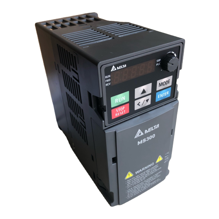
Delta MS300 Series Manuals
Manuals and User Guides for Delta MS300 Series. We have
5
Delta MS300 Series manuals available for free PDF download: User Manual, Operation Manual, Manual
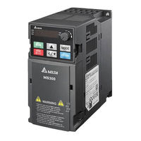
Delta MS300 Series User Manual (517 pages)
Standard Compact Drive
Brand:
Delta
| Category:
Storage
| Size: 19.19 MB
Table of Contents
Table of Contents
3
Chapter 1 Introduction
6
Nameplate Information
6
Model Name
6
Serial Number
6
RFI Jumper
6
Nameplate Information
7
Model Name
8
Serial Number
8
RFI Jumper
9
Isolating Main Power from Ground
10
Floating Ground System (IT Systems)
10
Asymmetric Ground System (Corner Grounded TN Systems)
11
Chapter 2 Dimension
12
Frame a
12
Frame B
13
Frame C
14
Frame D
15
Frame E
16
Frame F
17
Digital Keypad
18
Minimum Mounting Clearance and Installation
20
Minimum Mounting Clearance
20
Chapter 3 Installation
20
Chapter 4 Wiring
24
System Wiring Diagram
24
System Wiring Diagram
29
Chapter 5 Main Circuit Terminals
30
Main Power Terminals
31
Output Terminals for Main Circuit
31
Remove the Front Cover
32
Terminals for Connecting DC Reactor, External Brake Resistor and DC Circuit
32
Main Circuit Diagram
33
Main Circuit Terminals
34
Frame a
35
Frame B
36
Frame C
37
Frame D
38
Frame E
39
Frame F
40
Control Terminals
42
Analog Input Terminals (AVI, ACI, ACM)
42
Contact Input Terminals
42
Transistor Output Terminal (MO1, MO2, MCM)
42
Wiring Specifications of Control Terminal
43
Chapter 7 Optional Accessories
48
All Brake Resistors and Brake Units Used in AC Motor Drives
49
Non-Fuse Circuit Breaker
52
Fuse Specification Chart
54
AC/DC Reactor
56
Length of Motor Cable
67
Leakage Current to Affect the Motor and Counter Measurement
67
Surge Voltage to Affect the Motor and Counter Measurement
67
Zero Phase Reactors
70
Casing with Mechanical Fixed Part
70
Casing Without Mechanical Fixed Part
70
Zero Phase Reactor
71
Zero Phase Reactor for Signal Cable
72
EMC Filter
73
Filter Dimension
74
EMC Shield Plate
77
Capacitive Filter
80
Conduit Box
82
Fan Kit
90
Fan Removal
90
Keypad Panel Mounting
91
DIN-Rail Mounting
92
Mounting Adapter Plate
94
Chapter 8 Option Cards
98
Option Card Installation
99
CMM-MOD01 Modbus/Tcp Option Card
104
Communication Parameters for VFD-MS300 Connected to Ethernet
105
Basic Registers
105
LED Indicator & Troubleshooting
106
CMM-PD01 PROFIBUS Option Card
107
Environment
108
Connector Pin Assignment
108
CMM-DN01 Devicenet Option Card
109
CMM-EIP01 Modbus Tcp/Ethernet IP Option Card
112
CMM-COP01 Canopen Option Card
115
Canopen Communication Cable
116
Canopen Dimension
116
EMM-BPS01 Back-Up Power Supply Option Card
117
Chapter 9 Specification
118
Environment for Operation, Storage and Transportation
118
Derating of Ambient Temperature and Altitude
118
115V Series
119
230V Series
120
460V Series
122
Environment for Operation, Storage and Transportation
125
Derating of Ambient Temperature and Altitude
126
Appearance of KPMS-LE01 Keyboard Panel
130
Descriptions of Keypad Functions
130
Chapter 10 Digital Keypad
130
Keypad Operation Process
131
Main Page Selection
131
PLC Setting
131
F Page (Frequency Command Setting Page)
132
Application Selection Page
132
Parameter Setting
134
Unsigned Parameter
134
Reference Table for the 7-Segment LED Display of the Digital Keypad
136
Summary of Parameter Settings
138
00 Drive Parameters
138
Chapter 11 Summarpy of Parameters Settings
138
Basic Parameters
145
Digital Input / Output Parameters
149
Analog Input / Output Parameters
154
Multi-Stage Speed Parameters
158
Motor Parameters
159
Protection Parameters
162
Special Parameters
169
High-Function PID Parameters
172
Communication Parameters
174
Speed Feedback Control Parameters
179
Advanced Parameters
181
Macro / User Define Macro
182
Chapter 12 Description of Parameter Settings
186
Content of Multi-Function Display (User Defined)
187
Parameter Reset
187
Start-Up Display Selection
187
Coefficient Gain in Actual Output Frequency
189
Parameter Protection Password Input
189
Parameter Protection Password Setting
190
Control Mode
191
Control of Speed Mode
191
Carrier Frequency
192
Load Selection
192
PLC Command Mask
193
Source of the Master Frequency Command (AUTO)
193
Source of the Operation Command (AUTO)
194
Stop Method
194
Memory of Digital Operator (Keypad) Frequency Command
195
User Defined Characteristics
195
Сontrol of Motor Direction
195
LOCAL / REMOTE Selection
197
Max. User Defined Value
197
User Defined Value
197
Source of the Master Frequency Command (HAND)
198
Source of the Operation Command (HAND)
198
Digital Keypad STOP Function
199
Selection of Master and Auxiliary Frequency Command
199
Source of Auxiliary Frequency
199
Display Filter Time (Current)
200
Display Filter Time (Keypad)
200
Software Version (Date)
200
MID-Point Frequency 1 of Motor 2
202
MID-Point Voltage 1 of Motor 1
202
MID-Point Voltage 1 of Motor 2
202
MID-Point Voltage 1 of Motor 3
202
Min. Output Voltage of Motor 4
204
Output Frequency Lower Limit
206
Output Frequency Upper Limit
206
Accel. / Decel. Frequency
209
JOG Frequency
209
V/F Curve Selection
211
Zero-Speed Mode
211
Auto Acceleration / Deceleration Setting
212
Time for Canopen Quick Stop
212
Time Unit for Acceleration / Deceleration and S Curve
212
Deceleration Method
213
2-Wire / 3-Wire Operation Control
214
Digital Input / Output Parameter
214
Constant Speed. the Accel. / Decel. Speed of the up / down Key
222
UP / down Key Mode
222
Multi-Function Input Mode Selection
223
Multi-Function Input Response Time
223
Multi-Function Output Direction
229
Digital Output Gain (DFM)
230
Preliminary Counting Value Attained (Not Return to 0)
230
Terminal Counting Value Attained (Return to 0)
230
External Operation Control Selection after Reset and Activate
231
Output Frequency Setting for Multi-Function Output Terminal
231
The Width of the Desired Frequency Attained 2
231
Zero-Speed Level of Motor
231
Display the Status of Multi-Function Input Terminal
232
Status of Multi-Function Output Terminal
232
Display External Multi-Function Input Terminal Used by PLC
233
Display External Multi-Function Output Terminal Occupied by PLC
233
Automatic Positioning Deceleration Time
234
Display Memory of Frequency Command Used by External Terminal
234
EF Active When Terminal Count Value Attained
234
Multi-Function Output Terminal: Function 42: Brake Frequency Checking Point
234
Initial Frequency Command (F) Mode after Stop
235
Initial Frequency Command (F) Setting after Stop
235
Reverse Setting When Analog Signal Input Is Negative Frequency
237
Addition Function of the Analog Input
248
Analog Input Filter Time (ACI)
248
Analog Input Gain (ACI)
248
Multi-Function Output 1 (AFM)
249
Signal Loss Selection of Analog Input 4-20 Ma
249
AFM Output Bias
250
Analog Output When in REV Direction (AFM)
250
Gain of Analog Output (AFM)
250
ACI Terminal Input Selection
251
AVI Terminal Input Selection
251
Status of PLC Analog Output Terminal
251
AFM DC Output Setting Level
252
AFM Output Selection
252
Multi-Function MO Output by Source of AI Level
252
VR Positive / Negative Bias
252
ACI Lowest Point
253
ACI MID-Point
253
ACI Proportional Highest Point
253
Analog Input Curve Selection
253
AVI Voltage Lowest Point
254
AVI Voltage Proportional Highest Point
254
Negative AVI Voltage Lowest Point
254
Negative AVI Voltage Proportional Highest Point
255
Negative AVI Voltage Proportional Lowest Point
255
Full-Load Current of Induction Motor 1 (A)
258
Motor Parameter Auto Tuning
258
Pole Number of Induction Motor 1
258
Rated Power of Induction Motor 1 (Kw)
258
Delay Time for Y-Connection/△-Connection Switch of Induction Motor
260
Multi-Motors (Induction) Selection
260
Accumulative Motor Operation Time (Day)
262
Full-Load Current of Permanent Magnet Synchronous Motor
262
Induction Motor (IM) or Permanent Magnet Synchronous Motor Selection
262
Full-Load Current of Induction Motor 3 (A)
263
Rated Power of Induction Motor 3 (Kw)
263
Rated Power of Permanent Magnet Synchronous Motor
263
Full-Load Current of Induction Motor 4 (A)
264
No-Load Current of Induction Motor 3 (A)
264
Pole Number of Induction Motor 3
264
Rated Speed of Induction Motor 3 (Rpm)
264
No-Load Current of Induction Motor 4 (A)
265
Pole Number of Induction Motor 4
265
Stator Resistance (Rs) of Induction Motor 4
265
Low Voltage Level
266
Over-Voltage Stall Prevention
266
Selection for Over-Voltage Stall Prevention
267
Over-Current Stall Prevention During Acceleration
268
Accel. / Decel. Time Selection of Stall Prevention at Constant Speed
269
Over-Current Stall Prevention During Operation
269
Over-Torque Detection Selection (Motor 1)
269
Over-Torque Detection Selection (Motor 2)
270
Over-Torque Detection Time (Motor 2)
270
Temperature Level Over-Heat (OH) Warning
272
Stall Prevention Limit Level
273
Frequency Command for Malfunction
278
Output Frequency at Malfunction
278
PTC Detection Selection
278
PTC Level
278
DC Voltage at Malfunction
279
IGBT Temperature at Malfunction
279
Motor Speed in Rpm at Malfunction
279
Output Current at Malfunction
279
DC Brake Time of Output Phase Loss
280
STO Latch Selection
280
Treatment to Output Phase Loss Detection (OPHL)
280
Derating Protection
283
Lvx Auto Reset
283
Treatment for the Detected Input Phase Loss (Orp)
283
PT100 Level 1 Frequency Protection
285
PT100 Voltage Level 2
285
Delay Time of Activating PT100 Level 1 Frequency Protection
286
Software Detection GFF Filter Time
287
Low Current Detection Time
288
Low Current Setting Level
288
Treatment for Low Current
288
DC Brake Current Level
289
DC Brake Time at Startup
289
DC Brake Time at Stop
289
Software Brake Level
289
DC Brake Start Frequency
290
Restart after Momentary Power Loss
290
Voltage Incrasing Gain
290
Allowed Power Loss Duration
291
Base Block Time
291
Deb Function Selection
293
Restart Times after Fault
293
Speed Tracking During Start-Up
293
Treatment of Restart after Fault
293
Dwell Frequency at Decel
296
Deceleration of Emergency or Forced Stop
297
Fan Cooling Control
297
Auto Energy-Saving Setting
298
Auto Voltage Regulation (AVR) Function
298
Energy-Saving Gain
298
Filter Time of Slip Compensation (V/F and SVC Control Mode)
299
Filter Time of Torque Command (V/F and SVC Control Mode)
299
Torque Compensation Gain
299
Detection Time of Slip Deviation
300
Slip Compensation Gain (V/F and SVC Control Mode)
300
Slip Deviation Level
300
Treatment of Slip Deviation
300
Motor Shock Compensation Factor
301
OOB Average Sampling Angle
301
Return Time of Fault Restart
301
Terminal Selection of PID Feedback
302
Derivative Time (D)
304
Integral Time (I)
304
Proportional Gain (P)
304
PID Feedback Value by Communication Protocol
305
PID Mode Selection
305
PID Output Command Limit (Positive Limit)
305
Upper Limit of Integral Control
305
PD Control
306
PI Control
306
PID Control
306
Feedback Signal Detection Time
307
Feedback Signal Fault Treatment
307
Parallel Connection
307
Filter Time for PID Feedback
308
PID Compensation Selection
308
Sleep Time
308
Wake-Up Frequency
308
Enable PID to Change the Operation Direction
309
PID Compensation
309
Setting of Sleep Mode Function
309
Wake-Up Integral Limit
309
Frequency Command (PID Is Not in Use, Pr. 08-00 = 0. Only Works in VF Mode)
310
Frequency Command Calculation of the Internal PID
310
Acceleration / Deceleration Time of PID Command
311
PID Feedback Rate Percentage (Use PID, Pr. 08-00 ≠ 0 and Pr. 08-18 = 1)
311
PID Output Command Limit (Reverse Limit)
311
Selection of Frequency Base Corresponding to 100.00 % PID
312
COM1 Communication Protocol
313
COM1 Transmission Fault Treatment
313
COM1 Transmission Speed
313
Communication Address
313
Code Description
314
Data Format
314
Communication Protocol
315
Address List
320
Delay Time of Communication Response
323
Main Frequency of the Communication
323
Communication Decoding Method
324
PLC Command Force to 0
324
Canopen Communication Status
325
Canopen Decoding Method
325
Canopen Speed
325
Canopen Warning Record
325
Canopen Control Status
326
Canopen Reset Index
326
Identifications for Communication Card
326
Setting of Devicenet Speed
326
IP Configuration of the Communication Card
327
Other Setting of Devicenet Speed
327
Additional Setting for Communication Card
328
Reset Communication Card
328
Status of Communication Card
328
Encoder Input Type Setting
329
Encoder Pulse Per Round
329
Encoder Type Selection
329
PG2 Pulse Input Speed Command Filter Time
331
Pulse Input Type Setting
331
Treatment for Encoder Stall and Slip Error
331
I/F Mode, Current Command
332
PG2 Pulse Input Speed Command Mode
332
PM FOC Sensorless Speed Estimator Bandwidth
332
Top Limit of Frequency Deviation
332
Frequency Point When Switch from I/F Mode to PM Sensorless Mode
333
Frequency Point When Switch from PM Sensorless Mode to I/F Mode
333
Initial Angle Detection Pulse Value
333
Zero Voltage Time While Start up
333
Injection Frequency
334
Injection Magnitude
334
Position Detection Method
334
ASR 1 Gain
335
PWM Mode Selection
335
System Control
335
Application Selection
336
Adjustment & Application
348
Flow Chart of Adjustment When Starting up with Load
349
PMSVC Control Diagram
350
I/F Mode Current Command
351
Chapter 13 Warning Codes
355
Chapter 14 Error Codes
361
Chapter 15 Canopen Overview
371
Delta Canopen Supporting Functions
372
Delta Canopen Supporting Services
372
Delta Canopen Not Supporting Service
372
Canopen Protocol
373
RJ-45 Pin Definition
373
Canopen Communication Protocol
374
NMT (Network Management Object)
374
SDO (Service Data Objects)
375
PDO (Process Data Object)
375
EMCY (Emergency Object)
375
Wiring for Canopen
376
Canopen Communication Interface Descriptions
377
Canopen Control Mode Selection
377
DS402 Standard Control Mode
378
Related Set up of Ac Motor Drive (by Following DS402 Standard)
378
The Status of the Motor Drive (by Following DS402 Standard)
378
Various Mode Control Method (by Following DS402 Standard)
380
Speed Mode
380
By Using Delta Standard (Old Definition, Only Support Speed Mode)
382
Various Mode Control Method (Delta Old Standard)
382
By Speed Mode
382
By Using Delta Standard (New Definition)
383
Related Set up of Ac Motor Drive (Delta New Standard)
383
DI/DO AI AO Are Controlled Via Canopen
384
Canopen Supporting Index
385
Delta Standard Mode (Old Definition)
385
Delta Standard Mode (New Definition)
389
DS402 Standard
390
Canopen Fault Codes
391
Canopen LED Function
399
Chapter 16 Plc Function Applications
401
Wplsoft Ladder Diagram Editing Tool
402
Notes before PLC Use
403
Turn on
405
Connect to PC
405
I/O Device Explanation
407
Installation Wplsoft
407
Program Writing
407
Basic Operation
411
Basic Principles of PLC Ladder Diagrams
414
Schematic Diagram of PLC Ladder Diagram Program Scanning
414
Introduction to Ladder Diagrams
414
Ladder Diagram Images and Their Explanation
416
Overview of PLC Ladder Diagram Editing
417
Explanation of Basic Structure of Ladder Diagrams
417
Commonly-Used Basic Program Design Examples
419
Start, Stop, and Protection
419
Commonly-Used Control Circuits
420
Interlocking Control
421
Sequence Control
421
Oscillating Circuit
421
Flashing Circuit
422
Triggering Circuit
422
Delay Circuit
423
Extended Timing Circuit
423
Various PLC Device Functions
424
Introduction to Device Functions
425
Input/Output Contact Functions
425
Output Contact y Functions
425
Binary Number, bin
425
Octal Number, OCT
426
Decimal Number, DEC
426
Binary Code Decimal, BCD
426
Hexadecimal Number, HEX
426
Functions of Auxiliary Relays
427
Timer Functions
427
Counter Features
427
Counter Functions
427
Introduction to Special Relay Functions (Special M)
429
Introduction to Special Register Functions (Special D)
430
Introduction to the Command Window
433
Overview of Basic Commands
433
Detailed Explanation of Basic Commands
435
Series Circuit Block
437
Parallel Circuit Block
437
Read Stack (Pointer Does Not Change)
437
Clear Contact or Register
439
16-Bit Timer
439
16-Bit Counter
439
Connect/Release a Common Series Contact
440
Start of Forward Edge Detection Action
441
Start of Reverse Edge Detection Action
441
Forward Edge Detection Series Connection
441
Reverse Edge Detection Series Connection
442
Forward Edge Detection Parallel Connection
442
Reverse Edge Detection Parallel Connection
442
Upper Differential Output
443
Lower Differential Output
443
Program Conclusion
443
No Action
444
Inverse of Operation Results
444
Index
444
Overview of Application Commands
445
Detailed Explanation of Applications Commands
448
Call Subprogram
448
Conclusion of Subprogram
448
Conclusion a Main Program
449
Compares Set Output
450
Range Comparison
451
Data Movement
452
Send All
453
BIN Addition
454
BIN Subtraction
455
BIN Multiplication
456
BIN Division
457
BIN Add One
458
BIN Subtract One
459
Right Rotation
460
Left Rotation
461
Clear Range
462
BIN Whole Number - Binary Decimal Transformation
463
Comparison of Binary Floating Point Numbers
464
Comparison of Binary Floating Point Number Range
465
Angle - Diameter
466
Adding Binary Floating Point Numbers
468
Subtraction of Binary Floating Point Numbers
469
Multiplication of Binary Floating Point Numbers
470
Division of Binary Floating Point Numbers
471
Binary Floating Point Number Obtain Exponent
472
Binary Floating Point Number Obtain Logarithm
473
Binary Floating Point Number Find Square Root
474
Binary Floating Point Number - bin Whole Number Transformation
475
Binary Floating Point Number sin Operation
476
Binary Floating Point Number COS Operation
477
Binary Floating Point Number tan Operation
478
Binary Floating Point Number ASIN Operation
479
Binary Floating Point Number ACOS Operation
480
Binary Floating Point Number ATAN Operation
481
Binary Floating Point Number SINH Operation
482
Binary Floating Point Number COSH Operation
483
Binary Floating Point Number TANH Operation
484
BIN-GRAY Code Transformation
485
GRAY Code - bin Transformation
486
Contact Form Logical Operation LD#
487
Contact Form Logical Operation AND#
488
Contact Form Logical Operation OR#
489
Contact Form Compare LD
490
Contact Form Compare AND*
491
Contact Form Compare or
492
Floating Point Number Contact Form Compare LD
493
Floating Point Number Contact Form Compare and
494
Floating Point Number Contact Form Compare or
495
Detailed Explanation of Drive Special Applications Commands
496
Read Servo Parameter
496
Write Servo Parameter
496
Drive PID Control Mode
497
Drive Speed Control Mode
498
Error Display and Handling
500
Explanation of PLC Speed Mode Control
501
Count Function Using Pulse Input
503
High-Speed Count Function
503
Frequency Calculation Function
503
Chapter 17 Safe Torque off Function
505
Basic Function Description
506
The Circuit Diagram of Safe Torque off Function
506
Safe Torque off Terminal Function Description
507
Wiring Diagram
508
Failure Rate of the Drive Safety Function
509
Reset the Parameter Settings
509
Timing Diagram Description
510
Normal Operation Status
510
Error Code and Troubleshooting Instructions
513
Error Code Description
513
Troubleshooting Instructions
514
Test and Fault Confirmation
515
Advertisement
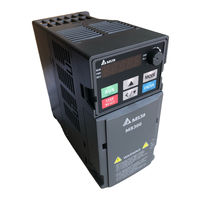
Delta MS300 Series User Manual (805 pages)
Standard Compact Drive
Brand:
Delta
| Category:
DC Drives
| Size: 36.06 MB
Table of Contents
Table of Contents
5
Introduction
10
Nameplate Information
10
Model Name
10
Serial Number
10
Apply after Service by Mobile Device
10
RFI Jumper
15
Dimensions
18
Frame a
19
Frame B
20
Frame C
21
Frame D
22
Frame E
23
Frame F
24
Digital Keypad
25
Installation
26
Mounting Clearance
26
Airflow and Power Dissipation
26
Wiring
30
System Wiring Diagram
30
Wiring
33
Main Circuit Terminals
34
Main Circuit Diagram
39
Main Circuit Terminal Specifications
40
Control Terminals
48
Control Terminal Specifications
48
Optional Accessories
56
Brake Resistors and Brake Units Used in AC Motor Drives
56
Magnetic Contactor / Air Circuit Breaker and Non-Fuse Circuit Breaker
56
Fuse Specification Chart
56
AC / DC Reactor
56
Zero Phase Reactors
56
EMC Filter
94
EMC Shield Plate
100
Capacitive Filter
103
NEMA 1 / UL Type 1 Kit
105
Fan Kit
113
Keypad Panel Mounting
114
DIN-Rail Mounting
116
Mounting Adapter Plate
118
Digital Keypad KPC-CC01
122
Option Cards
158
Option Card Installation
158
CMM-DN02 - Communication Card, Devicenet
167
EMM-BPS02 -- +24V Power Extension Card
183
Delta Standard Fieldbus Cables
185
Specifications
186
Models
186
General Specifications
186
Environment for Operation, Storage and Transportation
186
Derating for Ambient Temperature, Altitude and Carrier Frequency
186
Digital Keypad
204
KPMS-LE01 Keyboard Panel
204
Keypad Operation Process
204
Reference Table for the Seven-Segment Digital Keypad LED Display
204
Summary of Parameter Settings
214
Drive Parameters
215
Basic Parameters
222
Digital Input / Output Parameters
227
Analog Input / Output Parameters
233
Multi-Step Speed Parameters
237
Motor Parameters
238
Protection Parameters (1)
242
Special Parameters
249
High-Function PID Parameters
252
Communication Parameters
255
Speed Feedback Control Parameters
260
Advanced Parameters
262
Industry Application Parameters
264
Protection Parameters (2)
265
Descriptions of Parameter Settings
268
Drive Parameters
269
Basic Parameters
290
Digital Input / Output Parameters
304
Analog Input / Output Parameters
330
Multi-Step Speed Parameters
352
Motor Parameters
354
Protection Parameters (1)
364
Special Parameters
390
High-Function PID Parameters
406
Communication Parameters
424
Speed Feedback Control Parameters
432
Advanced Parameters
440
Industry Application Parameters
450
Protection Parameters (2)
460
Adjustment & Application
466
Warning Codes
480
Fault Codes
554
Canopen Overview
640
Wiring for Canopen
640
Canopen Communication Interface Descriptions
640
Canopen Supported Index
640
Canopen Fault Codes
640
Canopen LED Function
640
PLC Function Applications
666
PLC Summary
666
Notes before Using a PLC
666
Turn on
670
Basic Principles of PLC Ladder Diagrams
681
Various PLC Device Functions
693
Introduction to the Command Window
702
Error Display and Handling
771
Explanation of PLC Speed Mode Control
772
Count Function Using Pulse Input
774
Safe Torque off Function
776
Basic Function Description
776
Safe Torque off Terminal Function Description
776
Wiring Diagram
779
Failure Rate of the Drive Safety Function
780
Reset the Parameter Settings
781
Timing Diagram Description
782
Error Code and Troubleshooting Instructions
785
Test and Fault Confirmation
787
Modbus Protocol
790
Delta MS300 Series Operation Manual (64 pages)
EtherCAT Communication Card
Brand:
Delta
| Category:
Computer Hardware
| Size: 13.28 MB
Table of Contents
Table of Contents
4
Introduction
6
Network Functions and Specifications
6
Product Appearance
7
Panel Cut out Dimensions
7
Components
7
LED Indicators
8
RJ45 PIN Definition
8
Application
8
Applicable Firmware Version and Supporting Mode
8
Installation and Wiring
9
Mounting Position of Communication Card
9
Install and Remove Option Cards
10
Communication Cable and Grounding
10
Communication Cable
10
Grounding
11
MS300 Installation
13
MS300 Mounting Position 1 (See Section 2.1 for Details on Mounting Position) Frame A-F
13
MH300 Installation
15
MH300 Mounting Position 1 (See Section 2.1 for Details on Mounting Position) - Frame a - I
15
Network Connection
18
MH300 / MS300 Drive Settings
18
ESI (Ethercat Slave Information)
18
Introduction to Ethercat
19
Protocol
19
Ethercat State Machine
20
System Setup
21
Asynchronous
21
PDO Mapping Configuration
22
Default PDO Mapping Configuration
22
Set PDO Mapping
23
Cia402 Equipment Regulation
24
Canopen over Ethernet (Coe) State Machine
24
Ethercat Operation Mode
26
Velocity Mode
26
Communication Warning / Fault Table
28
Motor Drive Warning / Fault Table
28
SDO Abort Code
29
Operation Example
30
Delta PLC-AX-8 Operation Example (Designer-AX (Codesys Base))
30
Delta PLC - AH10EMC Operation Example (ECAT Builder)
39
Description of Object Specification
49
Object Type
49
Data Type
49
Object Dictionary
50
OD 1000H Communication Group
50
OD 3000H Motor Drive's Parameter Group
50
OD 6000H Communication Object Group
50
Detailed Information about Objects
51
OD 1000H Communication Group
51
OD 3000H Motor Drive's Parameter Group
56
OD 6000H Communication Object Group
57
Advertisement
Delta MS300 Series Operation Manual (56 pages)
PROFINET Communication Card
Brand:
Delta
| Category:
Conference System
| Size: 11.5 MB
Table of Contents
Table of Contents
3
Introduction
4
Introduction to PROFINET IO Communication
4
Features
4
Network Functions and Specifications
4
Product Appearance and Components
6
Exterior Dimensions
6
Introduction to each Component
6
LED Indicators
7
Definition of RJ45 Pin
7
MAC Address Definition
8
Installation and Wiring
9
Mounting Position of Communication Cards
9
Communication Cable
10
MS300 Installation
11
MH300 Installation
13
Connecting to the Network
16
MH300/MS300 Drive Settings
17
PROFINET Communication Profile
18
Profinet Comm. Card Info. (Identification & Maintenance Functions (I&M))
18
MS300/MH300 Real-Time Data Access Method(List of Control Words and Status Words)
19
Motor Drive Handling When Disconnection
21
Connection Configuration to Host Controller
23
Basic Configuration
23
Speed Mode DEMO (S7-300 + STEP 7)
28
Speed Mode DEMO (S7-1500 + TIA PORTAL)
38
Demonstration of Reading/Writing Synchronous and Asynchronous Parameters
48
Delta MS300 Series Manual (16 pages)
Brand:
Delta
| Category:
DC Drives
| Size: 1.2 MB
Table of Contents
Nameplate Information
2
Apply after Service by Mobile Device
4
RFI Jumper
5
Fuse Specification Chart
13
Emc Filter
16
Advertisement
Related Products
DELTA ShopMaster MS350
Delta ShopMaster MS275
Delta ShopMaster MS150
Delta ShopMaster MS265
Delta MS450
Delta ShopMaster MS250
Delta MS210
Delta M Series
Delta Compact Drive MS300 IP66/NEMA 4X Series
Delta MS-ACT50-4K
Delta Categories
Plumbing Product
Kitchen & Bath Fixtures
Bathroom Fixtures
Saw
Power Supply
More Delta Manuals
Login
Sign In
OR
Sign in with Facebook
Sign in with Google
Upload manual
Upload from disk
Upload from URL