Table of Contents
Advertisement
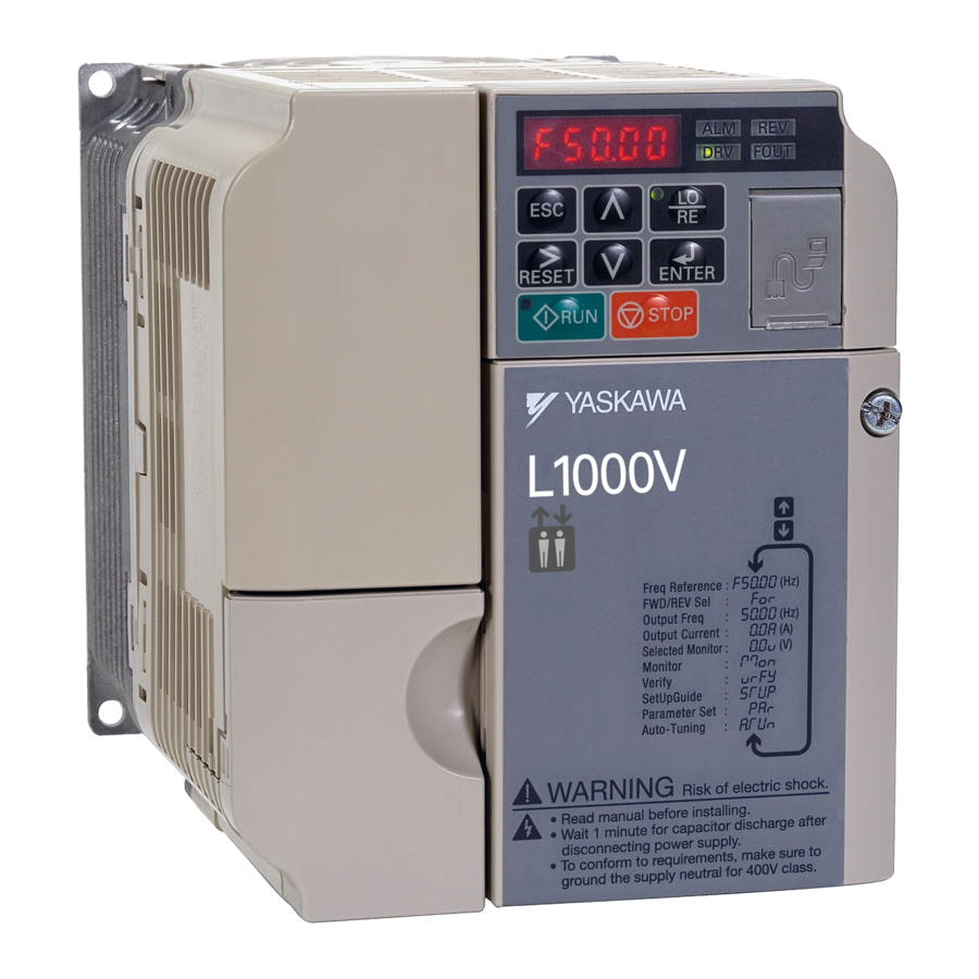
YASKAWA AC Drive L1000V
AC Drive for Elevator Applications
Technical Manual
Type: CIMR-LC V
Models: 200 V Class: 4.0 to 15 kW
400 V Class: 4.0 to 15 kW
To properly use the product, read this manual thoroughly and retain
for easy reference, inspection, and maintenance. Ensure the end user
receives this manual.
MANUAL NO. SIEP C710606 50A
1
1
Receiving
2
2
Mechanical Installation
3
3
Electrical Installation
Start-Up Programming &
4
4
Operation
5
5
Parameter Details
6
6
Troubleshooting
Periodic Inspection &
7
7
Maintenance
Peripheral Devices &
8
8
Options
A
A
Specifications
B
B
Parameter List
MEMOBUS/Modbus
C
C
Communications
D
D
Standards Compliance
E
E
Quick Reference Sheet
Advertisement
Table of Contents
Troubleshooting

Subscribe to Our Youtube Channel
Related Manuals for YASKAWA L1000V


Summary of Contents for YASKAWA L1000V
- Page 1 YASKAWA AC Drive L1000V AC Drive for Elevator Applications Technical Manual Type: CIMR-LC V Models: 200 V Class: 4.0 to 15 kW 400 V Class: 4.0 to 15 kW To properly use the product, read this manual thoroughly and retain for easy reference, inspection, and maintenance.
- Page 2 Yaskawa. No patent liability is assumed with respect to the use of the information contained herein. Moreover, because Yaskawa is constantly striving to improve its high-quality products, the information contained in this manual is subject to change without notice.
-
Page 3: Quick Reference
Refer to Setup Troubleshooting and Possible Solutions on page Standards Compliance Refer to European Standards on page 254 andRefer to UL and CSA Standards on page 258 Refer to UL and CSA Standards on page 258. YASKAWA EUROPE SIEP YASKAWA AC Drive L1000V Technical Manual... - Page 4 YASKAWA EUROPE SIEP YASKAWA AC Drive L1000V Technical Manual...
-
Page 5: Table Of Contents
L1000V Model Overview ........ - Page 6 Accel/Decel Ramp and Jerk Settings ........86 YASKAWA EUROPE SIEP YASKAWA AC Drive L1000V Technical Manual...
- Page 7 5.9 n: Special Adjustments..........147 YASKAWA EUROPE SIEP YASKAWA AC Drive L1000V Technical Manual...
- Page 8 Terminal Board ............198 YASKAWA EUROPE SIEP YASKAWA AC Drive L1000V Technical Manual...
- Page 9 EMC Guidelines Compliance ......... . . 253 YASKAWA EUROPE SIEP YASKAWA AC Drive L1000V Technical Manual...
- Page 10 D.3 User Setting Table ..........268 Index ..........................270 Revision History ......................271 YASKAWA EUROPE SIEP YASKAWA AC Drive L1000V Technical Manual...
-
Page 11: Preface & General Safety
Preface & General Safety This section provides safety messages pertinent to this product that, if not heeded, may result in fatality, personal injury, or equipment damage. Yaskawa is not responsible for the consequences of ignoring these instructions. I.1 PREFACE ............12 I.2 GENERAL SAFETY . -
Page 12: Preface
Any warnings provided by Yaskawa must be promptly provided to the end user. Yaskawa offers an express warranty only as to the quality of its products in conforming to standards and specifications published in the Yaskawa manual. -
Page 13: Supplemental Safety Information
• The products and specifications described in this manual or the content and presentation of the manual may be changed without notice to improve the product and/ or the manual. • When ordering a new copy of the manual due to damage or loss, contact your Yaskawa representative or the nearest Yaskawa sales office and provide the manual number shown on the front cover. -
Page 14: Safety Messages
Do not attempt to modify or alter the drive in any way not explained in this manual. Yaskawa is not responsible for damage caused by modification of the product made by the user. Failure to comply could result in death or serious injury from operation of damaged equipment. -
Page 15: I.2 General Safety
Failure to comply may result in minor or moderate injury from the main body of the drive falling. Burn Hazard Do not touch the heatsink or braking resistor hardware until a powered-down cooling period has elapsed. YASKAWA EUROPE SIEP YASKAWA AC Drive L1000V Technical Manual... - Page 16 Failure to comply could result in damage to the drive and will void warranty. Yaskawa is not responsible for any modification of the product made by the user. This product must not be modified. Failure to comply could result in damage to the drive or braking circuit.
-
Page 17: Precautions For Ce Low Voltage Directive Compliance
When the drive faults out, a protective circuit is activated and drive output is shut off. This, however, does not stop the motor immediately. Some type of mechanical brake may be needed if it is necessary to halt the motor faster than the Fast Stop function is able to. YASKAWA EUROPE SIEP YASKAWA AC Drive L1000V Technical Manual... - Page 18 Yaskawa offers protective designs for drives that must be used in areas subjected to oil mist and excessive vibration. Contact Yaskawa or your supplier for details.
-
Page 19: Motor Application Precautions
15 minutes to be sure that the heatsink has cooled down. Failure to comply may cause burn injury to personnel. Wiring Yaskawa recommends using ring terminals on all drive models for UL/cUL compliance. Use only the tools recommended by the terminal manufacturer for crimping. Transporting the Drive NOTICE: Never steam clean the drive. -
Page 20: Drive Label Warnings
Wait 5 minutes for capacitor discharge after disconnecting power supply To conform to requirements, make sure to ground the supply neutral for 400V class. Figure i.1 Warning Information Figure i.2 Warning Label Figure i.2 Warning Label Position YASKAWA EUROPE SIEP YASKAWA AC Drive L1000V Technical Manual... -
Page 21: Receiving
1.4 COMPONENT NAMES ..........25 YASKAWA EUROPE SIEP YASKAWA AC Drive L1000V Technical Manual... -
Page 22: Section Safety
Ensure that the motor is suitable for drive duty and/or the motor service factor is adequate to accommodate the additional heating with the intended operating conditions. YASKAWA EUROPE SIEP YASKAWA AC Drive L1000V Technical Manual... -
Page 23: General Description
Note: The drive automatically decreases the rated output current when setting higher carrier frequency. u Control Mode Selection Table 1.1 gives an overview of the L1000V motor control methods (control modes) and their various features. Table 1.1 Control Modes and their Features Motor Type... -
Page 24: Model Number And Nameplate Check
V1000 Based IP20 Type Region IP20 / Code NEMA Type 1 Europe Environmental Voltage Class Drive rated current Specification 3-phase, 200-240 Vac Standard 3-phase, 380-480 Vac Figure 1.2 Model Code Interpretation YASKAWA EUROPE SIEP YASKAWA AC Drive L1000V Technical Manual... -
Page 25: Component Names
D – Optional 24 V DC power K – LED operator supply connector cover E – Comm port L – Case F – Terminal board M – Cooling fan G – Front cover screw YASKAWA EUROPE SIEP YASKAWA AC Drive L1000V Technical Manual... - Page 26 E – Optional 24 V DC power M – Comm port supply connection cover F – Cover screws N – LED operator G – Rubber bushing O – Top cover H – Bottom cover YASKAWA EUROPE SIEP YASKAWA AC Drive L1000V Technical Manual...
-
Page 27: Front Views
A – Terminal board connector D – Protective Covers B – Jumper CN1 E – Main Circuit Terminals C – Control Circuit Terminals F – Ground Terminals Figure 1.3 Front View of Drives YASKAWA EUROPE SIEP YASKAWA AC Drive L1000V Technical Manual... - Page 28 1.4 Component Names YASKAWA EUROPE SIEP YASKAWA AC Drive L1000V Technical Manual...
-
Page 29: Mechanical Installation
2.2 MECHANICAL INSTALLATION ........31 YASKAWA EUROPE SIEP YASKAWA AC Drive L1000V Technical Manual... -
Page 30: Section Safety
Improper application of peripheral devices could result in malfunction of drive due to electrical interference. Follow manufacturers recommendations when installing electrical devices near the drive and take precautions to shield the drive from electrical interference. YASKAWA EUROPE SIEP YASKAWA AC Drive L1000V Technical Manual... -
Page 31: Mechanical Installation
Install the drive upright as illustrated in Figure 2.1 to maintain proper cooling. Refer to Mechanical Installation on page 31 for details on installing the drive. Figure 2.1 Not OK Not OK Figure 2.1 Correct Installation Orientation YASKAWA EUROPE SIEP YASKAWA AC Drive L1000V Technical Manual... - Page 32 Using this method, it is possible to replace the cooling fans later without removing the drive from the panel. YASKAWA EUROPE SIEP YASKAWA AC Drive L1000V Technical Manual...
-
Page 33: Digital Operator Remote Usage
Installation Types and Required Materials The digital operator can be mounted to an enclosure in two different ways: External/face-mount installs the operator outside the enclosure panel Internal/flush-mount installs the operator inside the enclosure panel YASKAWA EUROPE SIEP YASKAWA AC Drive L1000V Technical Manual... - Page 34 Digital Operator Phillips recessed pan head machine screw × 2 common_TMonly Enclosure panel Unit: mm Figure 2.6 External/Face-Mount Installation Figure 2.6 common_TMonly Unit: mm Figure 2.7 Panel Cut-Out Dimensions (External/Face-Mount Installation) YASKAWA EUROPE SIEP YASKAWA AC Drive L1000V Technical Manual...
- Page 35 2.2 Mechanical Installation Internal/Flush-Mount An internal flush-mount requires an installation support set that must be purchased separately. Contact a Yaskawa representative to order an installation support set and mounting hardware. Figure 2.8 illustrates how to attach Installation Support Set A.
-
Page 36: Exterior And Mounting Dimensions
Dimensions (mm) Model Weight CIMR-LC (kg) Fig. 2V0018B 2V0025F 2V0033F 2V0047F 2V0060F Table 2.4 Dimensions for three-phase 400V class drives Dimensions (mm) Model Weight CIMR-LC (kg) Fig. 4V0009B 4V0015F 4V0018F 4V0024F 4V0031F YASKAWA EUROPE SIEP YASKAWA AC Drive L1000V Technical Manual... -
Page 37: Electrical Installation
3.10 WIRING CHECKLIST ..........61 YASKAWA EUROPE SIEP YASKAWA AC Drive L1000V Technical Manual... -
Page 38: Section Safety
This drive can cause a residual current with a DC component in the protective earthing conductor. Where a residual current operated protective or monitoring device is used for protection in case of direct or indirect contact, always use an RCM or RCD of type B according to IEC 60755. YASKAWA EUROPE SIEP YASKAWA AC Drive L1000V Technical Manual... - Page 39 Carrying the drive by the front cover may cause the main body of the drive to fall, resulting in minor or moderate injury. Always hold the case when carrying the drive. YASKAWA EUROPE SIEP YASKAWA AC Drive L1000V Technical Manual...
- Page 40 Failure to comply could result in damage to the drive and will void warranty. Yaskawa is not responsible for any modification of the product made by the user. This product must not be modified. Check all the wiring to ensure that all connections are correct after installing the drive and connecting any other devices.
- Page 41 Insulate shields with heat shrink tubing or tape to prevent contact with other signal lines and equipment. Improper wiring practices could result in drive or equipment damage due to short circuit. YASKAWA EUROPE SIEP YASKAWA AC Drive L1000V Technical Manual...
-
Page 42: Standard Connection Diagram
NOTICE: Do not connect control circuit ground (AC) to drive enclosure. Improper drive grounding can cause control circuit malfunction. NOTICE: The minimum load for the relay outputs MA-MB-MC and MD-ME-MF is 10 mA. YASKAWA EUROPE SIEP YASKAWA AC Drive L1000V Technical Manual... - Page 43 Input (default setting) <6> <5> Symbols: Indicates a main circuit terminal. Use twisted pair cables. Use shielded twisted pair cables. Indicates a control circuit terminal. Figure 3.1 Drive Standard Connection Diagram YASKAWA EUROPE SIEP YASKAWA AC Drive L1000V Technical Manual...
- Page 44 NOTICE: When using the automatic fault reset function with wiring designed to shut off the power supply upon drive fault, make sure the drive does not trigger a fault output during fault reset (L5-02 = 0, default). Failure to comply will prevent the automatic fault reset function from working properly. YASKAWA EUROPE SIEP YASKAWA AC Drive L1000V Technical Manual...
-
Page 45: Main Circuit Connection Diagram
Braking DC reactor Resistor Unit (option) (option) Jumper B1 B2 Drive R/L1 U/T1 S/L2 V/T2 Motor T/L3 W/T3 Three-Phase Supply — 200 Vac (400 Vac) Figure 3.2 Connecting Main Circuit Terminals YASKAWA EUROPE SIEP YASKAWA AC Drive L1000V Technical Manual... -
Page 46: Terminal Block Configuration
Figure 3.3 Models: CIMR-LC2V0018 Models: CIMR-LC4V0009 CIMR-LC2V0025, 0033 CIMR-LC4V0015, 0018 Models: CIMR-LC2V0047 Model: CIMR-LC4V0024, 0031 CIMR-LC2V0060 Figure 3.3 Main Circuit Terminal Block Configurations YASKAWA EUROPE SIEP YASKAWA AC Drive L1000V Technical Manual... -
Page 47: Protective Covers
Apply pressure to the tabs on each side of the terminal cover. Pull the terminal cover away from the drive while pushing in on the tabs to remove it. Figure 3.5 YASKAWA EUROPE SIEP YASKAWA AC Drive L1000V Technical Manual... -
Page 48: Ip20 / Nema Type 1 Cover Removal And Installation
Figure 3.6 Removing the Front Covers Loosen the screw on the terminal cover to remove it and expose the conduit bracket. Figure 3.8 Figure 3.7 Removing the Screw to Expose Conduit Bracket YASKAWA EUROPE SIEP YASKAWA AC Drive L1000V Technical Manual... - Page 49 Properly connect all wiring after installing the drive and connecting other devices. Reattach all protective covers when wiring is complete. Figure 3.10 Figure 3.9 Reattaching the Protective Covers YASKAWA EUROPE SIEP YASKAWA AC Drive L1000V Technical Manual...
-
Page 50: Main Circuit Wiring
Closed-Loop Crimp Terminal Size (JIS C 2805) on page 258 for closed- loop crimp terminal recommendations. The wire gauges listed in the following tables are Yaskawa recommendations. Refer to local codes for proper wire gauge selections. YASKAWA EUROPE SIEP YASKAWA AC Drive L1000V Technical Manual... - Page 51 (17.7 to 22.1) –, +1, +2 4A0031 6 to 10 2 to 2.5 B1, B2 (10 to 8) (17.7 to 22.1) 6 to 16 4 to 6 (10 to 6) (35.4 to 53.1) YASKAWA EUROPE SIEP YASKAWA AC Drive L1000V Technical Manual...
-
Page 52: Main Circuit Terminal And Motor Wiring
50 m (164 ft.) or less 100 m (328 ft.) or less Greater than 100 m (328 ft.) Carrier Frequency 15 kHz or less 5 kHz or less 2 kHz or less YASKAWA EUROPE SIEP YASKAWA AC Drive L1000V Technical Manual... - Page 53 Improper wiring connections could cause the braking resistor to overheat and cause death or serious injury by fire. Failure to comply may result in damage to the braking circuit or drive. YASKAWA EUROPE SIEP YASKAWA AC Drive L1000V Technical Manual...
-
Page 54: Control Circuit Wiring
Pulse Train input High Level: 3.5 to 24 Vdc Pulse Train Inputs Low Level: 0.0 to 0.8 Vdc Input Impedance: 3kohm Used for single track PG speed feedback. Pulse Train input common YASKAWA EUROPE SIEP YASKAWA AC Drive L1000V Technical Manual... -
Page 55: Terminal Configuration
S7 HC SC H1 PC P1 AM AC RP AC S2 S3 S4 S5 S6 MA MB S7 HC SC H1 PC P1 S2 S3 S4 S5 S6 MA MB Figure 3.12 Control Circuit Terminal Arrangement YASKAWA EUROPE SIEP YASKAWA AC Drive L1000V Technical Manual... -
Page 56: Wiring The Control Circuit Terminal
(20) 0.25 to 1.5 (24 to 16) Ferrule-Type Wire Terminals Yaskawa recommends using CRIMPFOX 6, a crimping tool manufactured by PHOENIX CONTACT, to prepare wire ends with insulated sleeves before connecting to the drive. Refer to Table 3.8 for dimensions. - Page 57 Use a screwdriver with a blade width of max 2.5 mm and a thickness of max 0.4 mm Control Wires Terminal Board Figure 3.15 Removing Wires from the Terminal Board YASKAWA EUROPE SIEP YASKAWA AC Drive L1000V Technical Manual...
-
Page 58: Switches And Jumpers On The Terminal Board
Figure 3.18 Jumper CN1 AM AC RP AC S7 HC SC H1 PC P1 S2 S3 S4 S5 S6 MA MB Figure 3.17 Jumper CN1 Location on Terminal Board YASKAWA EUROPE SIEP YASKAWA AC Drive L1000V Technical Manual... -
Page 59: Control I/O Configuration
Table 3.9 Digital Input Sink / Source / External Power Supply Selection Drive Internal Power Supply External 24 Vdc Power Supply Sinking Mode (NPN) Sourcing Mode (PNP) Figure 3.19 External 24 Vdc Sink Source Power Supply Figure 3.18 Jumper CN1 Setting Possibilities YASKAWA EUROPE SIEP YASKAWA AC Drive L1000V Technical Manual... -
Page 60: Connect To A Pc
The drive can connect directly to a PC that is equipped with a serial port. Alternatively, an RS-232 to USB converter such as the optional Yaskawa Copy Unit (JVOP-181) can be used to connect to PCs not equipped with a serial port. After connection, Yaskawa DriveWizard Plus software can be used to monitor drive performance and manage parameter settings. -
Page 61: Wiring Checklist
Properly separate control circuit wiring and main circuit wiring. Analog signal line wiring should not exceed 50 m (164 ft.). Safe Disable input wiring should not exceed 30 m (98 ft.). YASKAWA EUROPE SIEP YASKAWA AC Drive L1000V Technical Manual... - Page 62 3.10 Wiring Checklist YASKAWA EUROPE SIEP YASKAWA AC Drive L1000V Technical Manual...
-
Page 63: Start-Up Programming & Operation
4.7 SETUP TROUBLESHOOTING AND POSSIBLE SOLUTIONS ....95 4.8 VERIFYING PARAMETER SETTINGS AND BACKING UP CHANGES ..98 YASKAWA EUROPE SIEP YASKAWA AC Drive L1000V Technical Manual... -
Page 64: Section Safety
Install additional emergency stop circuits separately from the drive emergency circuits. Failure to comply may result in personal injury. Remove the Up/Down Command before resetting alarms and faults. Failure to comply can result in death or serious injury. YASKAWA EUROPE SIEP YASKAWA AC Drive L1000V Technical Manual... - Page 65 Failure to comply may cause the drive to fault leaving the motor coasting, potentially damaging equipment. Correctly set parameter o2-04 when replacing the control terminal board. Failure to comply may result in drive damage due to lack of protective functions and poor drive performance. YASKAWA EUROPE SIEP YASKAWA AC Drive L1000V Technical Manual...
-
Page 66: Using The Led Operator
Lit while the operator is selected to run the drive (LOCAL mode). Refer to page for details. ALM LED Light REV LED Light Refer to LED Message Indicators on page 67 DRV LED Light FOUT LED Light YASKAWA EUROPE SIEP YASKAWA AC Drive L1000V Technical Manual... -
Page 67: Digital Text Display
• Drive mode is active. When DriveWorksEZ is used Drive is in programming mode. • Auto-Tuning Drive is currently displaying the output Drive is currently not displaying the output frequency. frequency. YASKAWA EUROPE SIEP YASKAWA AC Drive L1000V Technical Manual... -
Page 68: Lo/Re And Run Led Indicators
Figure 4.2 Flashing Flashing quickly Figure 4.2 LED Flashing Speeds Figure 4.3 Drive output speed during stop STOP STOP Up/Down Speed setting RUN LED Flashing Flashing Figure 4.3 Run LED Behaviour YASKAWA EUROPE SIEP YASKAWA AC Drive L1000V Technical Manual... -
Page 69: Menu Structure For Led Operator
In the Parameter Setting Mode all Parameter Setting Mode drive parameters can be set up. Auto-Tuning measures the motor data for optimal performance of Auto-Tuning the drive/motor combination. Figure 4.4 LED Operator Menu Structure YASKAWA EUROPE SIEP YASKAWA AC Drive L1000V Technical Manual... -
Page 70: The Drive And Programming Modes
The Drive and Programming Modes The L1000V has a Drive Mode to operate the motor and a Programming Mode to edit parameter settings. Drive Mode: In Drive Mode the user can operate the motor and observe U Monitor parameters. Parameter settings cannot be edited or changed when in Drive Mode. - Page 71 0.00% to 10.00% while in the Drive Mode. This example assumes the reference source is assigned to the digital operator (b1-02 = 0) and d1-01 is set to 0 or 3. YASKAWA EUROPE SIEP YASKAWA AC Drive L1000V Technical Manual...
-
Page 72: Changing Parameter Settings Or Values
C parameter group. Press until the “01” flashes. RESET Press to select the parameter C1-02. Press to view the current setting value (1.50 s). The left most digit flashes. YASKAWA EUROPE SIEP YASKAWA AC Drive L1000V Technical Manual... -
Page 73: Verifying Parameter Changes: Verify Menu
Left digit flashes. Repeat steps 8 through 10 of the previous table to change the value of the parameter. Press as many times as necessary to return to the frequency reference display. YASKAWA EUROPE SIEP YASKAWA AC Drive L1000V Technical Manual... -
Page 74: Simplified Setup Using The Setup Group
Frequency reference appears when powered up Press until appears STOP Press until d1-02 appears Change Select digit value to edit Confirm Returns automatically Displayed Change shortly accepted Figure 4.6 Setup Group Example YASKAWA EUROPE SIEP YASKAWA AC Drive L1000V Technical Manual... -
Page 75: Switching Between Local And Remote
Turn on the power to the drive. The initial display appears. Press . The LO/RE light will light up. The drive is now in LOCAL. To set the drive for REMOTE operation, press again. YASKAWA EUROPE SIEP YASKAWA AC Drive L1000V Technical Manual... -
Page 76: Start-Up Flowcharts
Perform a test run. Fine-tuning • Adjust settings for the brake sequence (S1- • Adjust speed control loop (C5- ) etc. FINISH Figure 4.7 Installation, Wiring, Basic Setup for Motor and Elevator YASKAWA EUROPE SIEP YASKAWA AC Drive L1000V Technical Manual... -
Page 77: Power On
The charge indicator LED will extinguish when the DC bus voltage is below 50 Vdc. To prevent electric shock, wait at least five minutes after all indicators are OFF and measure the DC bus voltage level to confirm safe level. YASKAWA EUROPE SIEP YASKAWA AC Drive L1000V Technical Manual... -
Page 78: Digital Lcd Operator Display Unit Selection
) to parameter o1-22. If a gearbox is not used, make Motor Traction Sheave sure o1-22 is set to 1.0. 5. Change parameter o1-03 to setting 4 or 5. The unit and setting values of related parameters will be changed automatically. YASKAWA EUROPE SIEP YASKAWA AC Drive L1000V Technical Manual... -
Page 79: Flowchart B: Auto-Tuning For Induction Motors
Apply the brake if it was released during Auto-tuning. Open the motor contactor(s). Open terminal H1 if used during the normal sequence. Open the Baseblock input (H1- =8/9) if used. FINISH Figure 4.8 Auto-Tuning for Induction Motors YASKAWA EUROPE SIEP YASKAWA AC Drive L1000V Technical Manual... -
Page 80: Auto-Tuning
The number of motor poles (T1-06) is usually not found on the motor nameplate, but it can be calculated by: p = (120 x f) / n Where f is the motor rated frequency and n is the motor synchronous speed. YASKAWA EUROPE SIEP YASKAWA AC Drive L1000V Technical Manual... -
Page 81: Before Auto-Tuning The Drive
If tuning results are abnormal or the STOP key is pressed before completion, Auto-Tuning will be interrupted and a fault code will appear on the LED operator. Figure 4.9 Auto-Tuning Normal Display Interrupted Figure 4.9 Auto-Tuning Interrupted Display YASKAWA EUROPE SIEP YASKAWA AC Drive L1000V Technical Manual... -
Page 82: Auto-Tuning Operation Example
• T1-04, Motor Rated Current • T1-05, Motor Base Frequency • T1-06, Number of Motor Poles • T1-07, Motor Base Speed Note: Refer to Input Data for Motor Auto-Tuning: T1 on page 83 for details. YASKAWA EUROPE SIEP YASKAWA AC Drive L1000V Technical Manual... -
Page 83: Input Data For Motor Auto-Tuning: T1
Setting 2: Stationary Auto-Tuning for Line-to-Line Resistance T1-02: Motor Rated Power Sets the motor rated power according to the motor nameplate value. Name Setting Range Default T1-02 Motor Rated Power 0.00 to 650.00 kW Determined by o2-04 YASKAWA EUROPE SIEP YASKAWA AC Drive L1000V Technical Manual... - Page 84 T1-07. Name Setting Range Default T1-07 Motor Base Speed 0 to 24000 r/min 1450 r/min YASKAWA EUROPE SIEP YASKAWA AC Drive L1000V Technical Manual...
-
Page 85: Setup Procedure For Elevator Applications
Failure to comply may cause injury or death due to inadvertent high speed operation. Speed Reference Selection Parameter b1-01 determines the source of the speed reference. On the L1000V drive the speed reference can only be modified through the digital operator or using digital inputs to switch between reference values. Therefore, this parameter cannot be modified from its default value of 0. -
Page 86: Speed Selection Using Digital Inputs (B1-01 = 0)
When d1-18 = 1 or 2, multi-function digital inputs are preset as shown below: Terminal Parameter Number Set Value Details H1-03 Nominal speed (d1-19) H1-04 Inspection speed (d1-24) H1-05 Intermediate speed (d1-20) H1-06 Leveling speed (d1-26) YASKAWA EUROPE SIEP YASKAWA AC Drive L1000V Technical Manual... - Page 87 DC Injection/ DC Injection/ Position lock Position lock Speed Safe disable (terminals H1/H2 on) and Baseblock off (H1- =8/9) Up/Down Command Leveling speed has priority Leveling speed Selected speed (other than leveling) YASKAWA EUROPE SIEP YASKAWA AC Drive L1000V Technical Manual...
-
Page 88: Multi-Function Terminal Setup
Units used to set the acceleration and deceleration ramp as well as the Jerk function change with the setting of parameter o1-03. Refer to Digital LCD Operator Display Unit Selection on page 78 for details. YASKAWA EUROPE SIEP YASKAWA AC Drive L1000V Technical Manual... -
Page 89: Inspection Operation
= 51 (Output Cont. Contr.) = 50 (Brake Control) = 50 (Brake Control) <1> The drive stops if either the Up/Down command or Inspection Operation signals are removed. Figure 4.11 Inspection Operation Sequence YASKAWA EUROPE SIEP YASKAWA AC Drive L1000V Technical Manual... -
Page 90: Brake Sequence
After the delay for the magnetic contactor set in S1-11 has passed, the drive resets the output terminal set for “Output Contactor Control” (H2- = 51). The Safe Disable Inputs can be cleared and Baseblock can be enabled. YASKAWA EUROPE SIEP YASKAWA AC Drive L1000V Technical Manual... -
Page 91: Rescue Operation
This may cause erroneous drive performance. NOTICE: In L1000V drives with software version 7010 power to the drive must be cycled after setting a digital input terminal to Rescue Operation (H1- =55) for the setting to take effect. - Page 92 4.6 Setup Procedure for Elevator Applications Select the configuration that matches your application. Follow the corresponding instructions for wiring and drive settings. For configurations not covered in the list above, contact your Yaskawa representative or our sales office directly for consultation.
- Page 93 1. After the car has stopped, open contactor A. 2. Clear the input terminal set for Rescue Operation (H1- = 55). 3. Close contactor B to return to operation with normal power supply. YASKAWA EUROPE SIEP YASKAWA AC Drive L1000V Technical Manual...
- Page 94 Elevator moves in the direction of the light load Off (open) = 55 On (closed) Light Load Direction Search status Off (open) = 54 Light load direction Figure 4.16 Light Load Direction Detection (Down) YASKAWA EUROPE SIEP YASKAWA AC Drive L1000V Technical Manual...
-
Page 95: Setup Troubleshooting And Possible Solutions
• Switch off the Up/Down command and then re-enter a new Up/Down command. when the drive was started from a REMOTE source. • o2-02 is set to 0 by default, i.e. the Stop button is disabled. YASKAWA EUROPE SIEP YASKAWA AC Drive L1000V Technical Manual... -
Page 96: Motor Is Too Hot
Excessive leakage current trips RCD/RCM. • Reduce the length of the cable used between the drive and the motor. • Install a noise filter or reactor on the output side of the drive. YASKAWA EUROPE SIEP YASKAWA AC Drive L1000V Technical Manual... -
Page 97: Riding Comfort Related Problems
Increase the Carrier Frequency in parameter C6-03. If the carrier frequency is The carrier frequency is too low. noise from the motor. set higher than the default setting, a current derating must be considered. YASKAWA EUROPE SIEP YASKAWA AC Drive L1000V Technical Manual... -
Page 98: Verifying Parameter Settings And Backing Up Changes
A1-04 correctly matches the value set to A1-05: A1-01, A1-02, A1-03 and A2-01 through A2-33. Note: Parameter A1-05 is hidden from view. To display A1-05, access parameter A1-04 and press simultaneously. YASKAWA EUROPE SIEP YASKAWA AC Drive L1000V Technical Manual... -
Page 99: Copy Function
Note: To obtain the driver and software of USB Copy Unit, Copy Unit Manager and DriveWizardPlus, access these sites: China: http://www.yaskawa.com cn Europe: http://www.yaskawa.eu.com Japan: http://www.e-mechatronics.com U.S.A.: http://www.yaskawa.com Other areas: contact a Yaskawa representative. YASKAWA EUROPE SIEP YASKAWA AC Drive L1000V Technical Manual... - Page 100 4.8 Verifying Parameter Settings and Backing Up Changes YASKAWA EUROPE SIEP YASKAWA AC Drive L1000V Technical Manual...
-
Page 101: Parameter Details
5.12 U: MONITOR PARAMETERS ........161 YASKAWA EUROPE SIEP YASKAWA AC Drive L1000V Technical Manual... -
Page 102: A: Initialization
Use this mode for simple speed control and for multiple motor applications with low demands to dynamic response or speed accuracy. This control mode is also used when the motor parameters are unknown and Auto-Tuning cannot be performed. YASKAWA EUROPE SIEP YASKAWA AC Drive L1000V Technical Manual... - Page 103 A1-04 correctly matches the value set to A1-05: A1-01, A1-02, A1-03, A1-06, and A2-01 through A2-33. The instructions below demonstrate how to set password “1234”. An explanation follows on how to enter that password to unlock the parameters. YASKAWA EUROPE SIEP YASKAWA AC Drive L1000V Technical Manual...
- Page 104 Press to enter the parameter menu tree. Press to change the flashing digit. RESET Press to scroll to A1-04. Press and Enter the password “1234”. Press to save the new password. YASKAWA EUROPE SIEP YASKAWA AC Drive L1000V Technical Manual...
-
Page 105: A2: User Parameters
A2-17, the second most recently to A2-18, and so on. Access the User Parameters using the Setup Mode of the digital operator. YASKAWA EUROPE SIEP YASKAWA AC Drive L1000V Technical Manual... -
Page 106: B: Application
Setting 2: Prohibit programming during run It is not possible to enter the Programming Mode as long as the drive output is active. The Programming Mode cannot be displayed during Run. YASKAWA EUROPE SIEP YASKAWA AC Drive L1000V Technical Manual... -
Page 107: B4: Delay Timers
Figure 5.1 Multi-function Contact On (Closed) Input: Timer Function Off (Open) Multi-function Contact On (Closed) common_TMo Output: Timer Function Off (Open) b4-01 b4-02 b4-01 b4-02 Figure 5.1 Timer Operation YASKAWA EUROPE SIEP YASKAWA AC Drive L1000V Technical Manual... -
Page 108: B6: Dwell Function
Dwell Speed at Stop 0.0 to 100.0% 0.0% <1> b6-04 Dwell Time at Stop 0.0 to 10.0 s 0.0 s <1> A setting of 100% is equal to the maximum speed. YASKAWA EUROPE SIEP YASKAWA AC Drive L1000V Technical Manual... -
Page 109: C: Tuning
Accel/Decel Ramp Selection 1 (Terminals S3 to S8, H1- = “7”) Accel/Decel Ramp Selection 2 (Terminals S3 to S8, H1- = “1A”) Figure 5.3 Timing Diagram of Accel/Decel Ramp Change YASKAWA EUROPE SIEP YASKAWA AC Drive L1000V Technical Manual... - Page 110 Sets the deceleration ramp during Inspection Run. Refer to Inspection Operation on page 89 for details. Parameter Name Setting Range Default C1-15 Inspection Deceleration Ramp 0.00 to 2.00 s 0.00 s <1> <1> YASKAWA EUROPE SIEP YASKAWA AC Drive L1000V Technical Manual...
-
Page 111: C2: Jerk Settings
• Increase the setting if the motor at constant speed is slower than the speed reference. • Decrease the setting if the motor at constant speed is faster than the speed reference. Parameter Name Setting Range Default C3-01 Slip Compensation Gain 0.0 to 2.5 YASKAWA EUROPE SIEP YASKAWA AC Drive L1000V Technical Manual... - Page 112 When selecting the drive, remember that the reduction in flux causes a slightly higher current at high speed when this function is enabled. Parameter Name Setting Range Default C3-05 Output Voltage Limit Operation Selection 0 or 1 Setting 0: Disabled Setting 1: Enabled YASKAWA EUROPE SIEP YASKAWA AC Drive L1000V Technical Manual...
-
Page 113: C4: Torque Compensation
Reverse Up/Down command. Setting 0.0% disables this feature. Parameter Name Setting Range Default C4-04 Torque Compensation at Reverse Start -200.0 to 0.0% 0.0% YASKAWA EUROPE SIEP YASKAWA AC Drive L1000V Technical Manual... -
Page 114: C5: Speed Control Loop
Adjust them in the opposite way if vibrations occur. Repeat steps 2 to 5 until the desired riding comfort has been reached. Also refer to Riding Comfort Related Problems on page YASKAWA EUROPE SIEP YASKAWA AC Drive L1000V Technical Manual... - Page 115 Figure 5.9. Figure 5.8 common P = C5-01 P, I I = C5-02 P = C5-03 I = C5-04 Speed C5-07 Figure 5.8 Settings at Low and High Speed during Acceleration YASKAWA EUROPE SIEP YASKAWA AC Drive L1000V Technical Manual...
-
Page 116: C6: Carrier Frequency
2: 5.0 kHz 3: 8.0 kHz 4: 10.0 kHz 5: 12.5 kHz 6: 15.0 kHz Note: Refer to Carrier Frequency Derating on page 220 when using a carrier frequency setting above 8.0 kHz. YASKAWA EUROPE SIEP YASKAWA AC Drive L1000V Technical Manual... -
Page 117: D: Reference Settings
<1> <1> Setting ranges and defaults vary by the setting units determined by parameter o1-03. Refer to Defaults and Setting Ranges by Display Unit Selection (o1-03) on page 250 for details. YASKAWA EUROPE SIEP YASKAWA AC Drive L1000V Technical Manual... - Page 118 Inspection Operation function when d1-18 = 0/3. Refer to Inspection Operation on page 89 for details. Name Setting Range Default d1-29 Inspection Speed Detection Level 0.00 to 120.00 Hz 0.00 Hz YASKAWA EUROPE SIEP YASKAWA AC Drive L1000V Technical Manual...
-
Page 119: E: Motor Parameters
<4> Default setting is determined by the drive model (o2-04). <5> Parameter ignored when E1-11 and E1-12 are set to 0.0. <6> Auto-Tuning will set E1-13 to the same value as E1-05. YASKAWA EUROPE SIEP YASKAWA AC Drive L1000V Technical Manual... -
Page 120: E2: Motor Parameters
E2-03 manually. Contact the motor manufacturer to receive a copy of the motor test report. Parameter Name Setting Range Default E2-03 Motor No-Load Current 0 to [E2-01] Determined by o2-04 YASKAWA EUROPE SIEP YASKAWA AC Drive L1000V Technical Manual... - Page 121 E2-10: Motor Iron Loss for Torque Compensation Sets the motor iron loss in watts. Parameter Name Setting Range Default E2-10 Motor Iron Loss for Torque Compensation 0 to 65535 W Determined by o2-04 YASKAWA EUROPE SIEP YASKAWA AC Drive L1000V Technical Manual...
- Page 122 Enter the no-load current at rated frequency and rated voltage to E2-03. The no-load current is not usually listed on the nameplate. Contact the motor manufacturer if the data cannot be found. The default setting of the no-load current is for performance with a 4-pole Yaskawa motor. Setting the Number of Motor Poles Only required in V/f Control with PG and Closed Loop Vector Control.
-
Page 123: F: Simple Feedbacksettings
Setting 0: Ramp to stop (uses the deceleration ramp set to C1-02) Setting 1: Coast to stop Setting 2: Fast Stop (uses the Fast Stop ramp set to C1-09) Setting 3: Alarm only (drive continues operating while “dEv” flashes on the screen) YASKAWA EUROPE SIEP YASKAWA AC Drive L1000V Technical Manual... -
Page 124: H: Terminal Functions
Select this setting when using the terminal in a pass-through mode. When set to F, an input does not trigger any function in the drive. Setting F, however, still allows the input status to be read out. YASKAWA EUROPE SIEP YASKAWA AC Drive L1000V Technical Manual... - Page 125 The following table shows the relationship between the conditions and the value set to H1- Terminal statuses, detection conditions, and stopping methods marked with an are applicable to the corresponding ” O ” settings. YASKAWA EUROPE SIEP YASKAWA AC Drive L1000V Technical Manual...
- Page 126 Initiates Rescue Operation when the terminal closes. Refer to Rescue Operation on page 91 for details. Setting 56: Motor contactor feedback Can be used as monitoring input for the motor contactor and allows the drive to detect contactor malfunction. YASKAWA EUROPE SIEP YASKAWA AC Drive L1000V Technical Manual...
-
Page 127: H2: Multi-Function Digital Outputs
The operating speed is below the minimum output frequency (E1-09) and the zero speed level at stop (S1-01). Figure 5.12 Output speed E1-09 (Max. Output Frequency) or motor speed S1-01 (Zero Speed Level) common_ TMonly Zero Speed Figure 5.12 Zero-Speed Time Chart YASKAWA EUROPE SIEP YASKAWA AC Drive L1000V Technical Manual... - Page 128 Output speed or motor speed is below L4-01 or has not exceeded L4-01 + L4-02. Note: Detection works in both forward and reverse. The value of L4-01 is used as the detection level for both directions. YASKAWA EUROPE SIEP YASKAWA AC Drive L1000V Technical Manual...
- Page 129 DC bus circuit will also cause the terminal to set for “DC bus undervoltage” to close. Status Description Open DC bus voltage is above the level set to L2-05 Closed DC bus voltage has fallen below the trip level set to L2-05. YASKAWA EUROPE SIEP YASKAWA AC Drive L1000V Technical Manual...
- Page 130 Output speed or motor speed is within the range of speed reference ±L4-04. Figure 5.17 Speed common_ reference L4-04 TMonly Output speed or motor speed L4-04 Speed Agree 2 Figure 5.17 Speed Agree 2 Time Chart YASKAWA EUROPE SIEP YASKAWA AC Drive L1000V Technical Manual...
- Page 131 L4-03 is a signed value, speed detection works in the specified direction only. Status Description Open Output speed or motor speed is below L4-03 minus L4-04 or has not exceeded L4-03 yet. Closed Output speed or motor speed exceeded L4-03. YASKAWA EUROPE SIEP YASKAWA AC Drive L1000V Technical Manual...
- Page 132 Setting 20: Drive overheat pre-alarm (oH) Output closes whenever the drive heatsink temperature reaches the level specified by parameter L8-02. Refer to L8-02: Overheat Alarm Level on page 144 for details on drive overheat detection. YASKAWA EUROPE SIEP YASKAWA AC Drive L1000V Technical Manual...
- Page 133 This terminal closes if the Safe Disable inputs H1-HC are closed and opens when terminals H1-HC are open. Note: This digital output function is only available on L1000V drives with firmware version 7011 and later. Setting 100 to 158: Functions 0 to 58 with Inverse Output These settings have the same function as settings 0 to 58 but with inverse output.
-
Page 134: H4: Multi-Function Analog Outputs
Figure 5.23 Analog Output Gain and Bias Setting Example 1 and 2 Example 3: Set H4-03 to 30% for an output signal of 3 V at terminal AM when the monitored value is at 0%. YASKAWA EUROPE SIEP YASKAWA AC Drive L1000V Technical Manual... -
Page 135: H6: Pulse Train Input
H6-09: PG Pulse Number Sets the number of pulses per revolution of the encoder used for feedback. Name Setting Range Default 1024 ppr H6-09 PG Pulse Number 500 to 10000 ppr YASKAWA EUROPE SIEP YASKAWA AC Drive L1000V Technical Manual... -
Page 136: L: Protection Functions
C: Max. speed for 132MJ and below Motor is designed to effectively cool itself even at Continuous operation with 100% load from 5 Hz to low speeds. 50 Hz. Continuous 100120 167 200 Speed (%) YASKAWA EUROPE SIEP YASKAWA AC Drive L1000V Technical Manual... - Page 137 • Hot start: Motor protection operation time in response to an overload situation that occurred during sustained operation at rated current. Figure 5.25 Operation time (minutes) common_TMo Cold start Hot start Motor current (%) E2-01 = 100% motor current Figure 5.25 Motor Protection Operation Time YASKAWA EUROPE SIEP YASKAWA AC Drive L1000V Technical Manual...
-
Page 138: L2: Undervoltage Detection
If the output current rises above the Stall Prevention level set in L3-02, then the drive stops accelerating. Acceleration will not resume until the output current falls 15% below the setting in L3-02. The Stall Prevention level is automatically reduced in the constant power range. YASKAWA EUROPE SIEP YASKAWA AC Drive L1000V Technical Manual... - Page 139 If the current exceeds the Stall Prevention level set in parameter L3-06, then the drive will decelerate at decel ramp 1 (C1-02). Once the current level drops below the value of L3-06 minus 2% for 100 ms, the drive accelerates back to the speed reference at the active acceleration ramp. YASKAWA EUROPE SIEP YASKAWA AC Drive L1000V Technical Manual...
-
Page 140: L4: Speed Detection
Braking Transistor Fault Overcurrent Undertorque Detection 1 Heatsink Overheat Undertorque Detection 2 Motor Overload Sequence Error 1 Drive Overload Sequence Error 2 Overtorque Detection 1 Sequence Error 3 Overtorque Detection 2 – – YASKAWA EUROPE SIEP YASKAWA AC Drive L1000V Technical Manual... - Page 141 Determines whether a limit should be placed on the number of reset attempts after a Uv1 fault. Name Setting Range Default L5-06 Undervoltage Fault Reset Selection 0 or 1 Setting 0: Restrict auto-reset attempts to L5-01 after Uv1 YASKAWA EUROPE SIEP YASKAWA AC Drive L1000V Technical Manual...
-
Page 142: L6: Torque Detection
Setting 2: oL3, oL4 at run (Alarm) Overtorque detection works as long as the Up/Down command is active. The operation continues after detection and an oL3 or oL4 alarm is triggered. YASKAWA EUROPE SIEP YASKAWA AC Drive L1000V Technical Manual... -
Page 143: L7: Torque Limit
Note: The maximum output torque is ultimately limited by the drive output current. Output torque will not exceed the limit set for the drive rated current, even if the torque limits are set to higher values. YASKAWA EUROPE SIEP YASKAWA AC Drive L1000V Technical Manual... -
Page 144: L8: Drive Protection
When an output terminal is set for the oH pre-alarm (H2- = 20), the switch will close when the heatsink temperature rises above L8-02. Name Setting Range Default L8-02 Overheat Alarm Level 50 to 130 °C Determined by o2-04 YASKAWA EUROPE SIEP YASKAWA AC Drive L1000V Technical Manual... - Page 145 Setting 2: Fault when two phases are lost An output phase loss fault (LF) is triggered when two output phases are lost. The output shuts off and the motor coasts to stop. YASKAWA EUROPE SIEP YASKAWA AC Drive L1000V Technical Manual...
- Page 146 L8-15: oL2 (Drive Overload) Characteristics Selection at Low Speeds Selects whether the drive overload capability (oL fault detection level) is reduced at low speeds in order to prevent premature output transistor failures. Note: Contact Yaskawa for consultation first before disabling this setting. Name Setting Range...
- Page 147 The carrier frequency is reduced at speeds below 6 Hz when output current exceeds 100% of drive rated current. The drive returns to its normal carrier frequency when output current falls below 88% of drive rated current or when the output frequency exceeds 7 Hz. YASKAWA EUROPE SIEP YASKAWA AC Drive L1000V Technical Manual...
- Page 148 Safe Disable Operation Drive Ready L8-88 Alarm Display during Safety Disable Alarm Output (H2- = 10 ) Selection (H2- = 6) 0 (mode 0) ALM flashes 1 (mode1) ALM flashes YASKAWA EUROPE SIEP YASKAWA AC Drive L1000V Technical Manual...
-
Page 149: N: Special Adjustments
The drive adjusts the output voltage during run to improve overload tolerance and minimize the effects of high temperatures on speed accuracy. Note: This setting can only be selected if the Energy Saving function is disabled (b8-01 = 0). YASKAWA EUROPE SIEP YASKAWA AC Drive L1000V Technical Manual... -
Page 150: O: Operator Related Settings
For example, to have the maximum output speed displayed as “100.00”, set the o1-10 = 1000 and o1-11 = 2 (i.e., 1000 with 2 decimal points). YASKAWA EUROPE SIEP YASKAWA AC Drive L1000V Technical Manual... -
Page 151: O2: Digital Operator Keypad Functions
Refer to A1-03: Initialize Parameters on page 103 for details on drive initialization. Name Setting Range Default o2-03 User Parameter Default Value 0 to 2 YASKAWA EUROPE SIEP YASKAWA AC Drive L1000V Technical Manual... - Page 152 Note: This parameter is effective only when the Run command is set to be given from the digital operator (b1-02 or b1-16 = 0) Name Setting Range Default o2-07 Motor Direction at Power Up when Using Operator 0 or 1 YASKAWA EUROPE SIEP YASKAWA AC Drive L1000V Technical Manual...
-
Page 153: O3: Copy Function
The drive logs the time that the output is active. This includes whenever the Up/Down command is active (even if the motor is not rotating) and when there is voltage output. YASKAWA EUROPE SIEP YASKAWA AC Drive L1000V Technical Manual... - Page 154 Resets the kWh monitors U4-10 and U4-11. Initializing the drive or cycling the power does not reset these monitors. Name Setting Range Default o4-12 kWh Monitor Initialization 0 or 1 Setting 0: No Action The kWh data are kept YASKAWA EUROPE SIEP YASKAWA AC Drive L1000V Technical Manual...
- Page 155 Resets the number of travels counter. The monitor U4-24/25 will show 0. Once o4-13 is set to 1 and the ENTER key is pressed, the counter value is erased and the display returns to 0. YASKAWA EUROPE SIEP YASKAWA AC Drive L1000V Technical Manual...
-
Page 156: S1: Brake Sequence
S1-04 when setting S1-06 to relatively long delay time. Parameter Name Setting Range Default S1-06 Brake Release Delay Time 0.00 to 10.00 s 0.20 s YASKAWA EUROPE SIEP YASKAWA AC Drive L1000V Technical Manual... -
Page 157: S2: Slip Compensation For Elevators
Sets the filter time constant applied to the torque signal used for the slip compensation value calculation. Parameter Name Setting Range Default S2-06 Slip Compensation Torque Detection Filter Time Constant 0 to 2000 ms 500 ms YASKAWA EUROPE SIEP YASKAWA AC Drive L1000V Technical Manual... -
Page 158: S4: Rescue Operation
Motor Contactor Response Error (SE1) Detection/Reset Selection 0 to 2 0: Detect during stop, SE1 must be manually reset 1: Detect during stop, SE1 can be automatically reset 2: No SE1 detection YASKAWA EUROPE SIEP YASKAWA AC Drive L1000V Technical Manual... - Page 159 The drive decelerates to stop with the active deceleration time. 1: Coast to Stop The motor will coast to stop and the brake control output terminal will immediately open, closing the brake. YASKAWA EUROPE SIEP YASKAWA AC Drive L1000V Technical Manual...
-
Page 160: T: Motor Tuning
5: No Detection Rollback detection is disabled. u T: Motor Tuning Auto-Tuning automatically sets and tunes parameters required for optimal motor performance. Refer to Auto-Tuning on page 80 for details on Auto-Tuning parameters. YASKAWA EUROPE SIEP YASKAWA AC Drive L1000V Technical Manual... -
Page 161: U: Monitor Parameters
• Reference data for the output voltage and vector control • Speed Loop and Inertia Compensation control monitors Refer to Figure 5.7 on page for details and an illustration showing where monitors are located in the speed control loop block. YASKAWA EUROPE SIEP YASKAWA AC Drive L1000V Technical Manual... - Page 162 5.12 U: Monitor Parameters YASKAWA EUROPE SIEP YASKAWA AC Drive L1000V Technical Manual...
-
Page 163: Troubleshooting
6.8 DIAGNOSING AND RESETTING FAULTS ....... 187 YASKAWA EUROPE SIEP YASKAWA AC Drive L1000V Technical Manual... -
Page 164: Section Safety
Tighten all terminal screws to the specified tightening torque. Loose electrical connections could result in death or serious injury by fire due to overheating of electrical connections. Improperly tightened terminal screws can also cause erroneous equipment operation. YASKAWA EUROPE SIEP YASKAWA AC Drive L1000V Technical Manual... - Page 165 Failure to comply could result in damage to the drive and will void warranty. Yaskawa is not responsible for modification of the product made by the user. Check all the wiring after installing the drive and connecting other devices to ensure that all connections are correct.
-
Page 166: Drive Alarms, Faults, And Errors
Check the LED operator for information about possible faults if the drive or motor fails to operate. Refer to Using the LED Operator on page If problems occur that are not covered in this manual, contact the nearest Yaskawa representative with the following information: • Drive model •... -
Page 167: Alarm And Error Displays
DC Bus Undervoltage feedback control modes) Control Power Supply Voltage Fault EF3 to External Fault (input terminal S3 to S7) Soft Charge Circuit Fault EEPROM Write Error Output Voltage Detection Error YASKAWA EUROPE SIEP YASKAWA AC Drive L1000V Technical Manual... - Page 168 Overspeed (for Control Mode with Encoder) DC Bus Overvoltage Encoder Disconnected (for Control Mode with Encoder) TrPC IGBT Maintenance Time (90%) Undertorque Detection 1 Undertorque Detection 2 Undervoltage Output Voltage Detection Error YASKAWA EUROPE SIEP YASKAWA AC Drive L1000V Technical Manual...
- Page 169 Communication error ndAT Model, voltage class, capacity mismatch rdEr Error reading data rEAd Reading parameter settings (flashing) vAEr Voltage class, capacity mismatch vFyE Parameter setting mismatch vrFy Comparing parameter settings (flashing) YASKAWA EUROPE SIEP YASKAWA AC Drive L1000V Technical Manual...
-
Page 170: Fault Detection
Possible Solution • Cycle power to the drive. Control circuit is damaged. • If the problem continues, replace the control board or the entire drive. Contact Yaskawa or a Yaskawa representative for instructions on replacing the control board. Digital Operator Display... - Page 171 Possible Solution • Cycle power to the drive. Hardware is damaged. • If the problem continues, replace the control board or the entire drive. Contact Yaskawa or a Yaskawa representative for instructions on replacing the control board. Digital Operator Display...
- Page 172 Refer to Diagnosing and Resetting Faults on page 187. • If the problem continues, replace the control board or the entire drive. Contact Yaskawa or a Yaskawa representative for instructions on replacing the control board. • If the problem continues, replace the control board or the entire drive. Contact Yaskawa or a Yaskawa representative for Hardware problem.
- Page 173 Terminal wires on the output side of the drive are loose. Apply the tightening torque specified in this manual to fasten the terminals. Refer to Wire Size on page If the problem continues, replace the control board or the entire drive. Contact Yaskawa or a Yaskawa representative for The output circuit is damaged.
- Page 174 Install a DC reactor. Surge voltage entering from the drive input power. Note: Voltage surge can result from a thyristor convertor and phase advancing capacitor using the same input power supply. YASKAWA EUROPE SIEP YASKAWA AC Drive L1000V Technical Manual...
- Page 175 • Stabilize drive input power or disable phase loss detection. • Check the maintenance time for the capacitors (U4-05). • Replace the capacitor if U4-05 is greater than 90%. For instructions on replacing the capacitor, contact Yaskawa or a Yaskawa representative.
- Page 176 Problem detected with the voltage on the output side of the drive. Cause Possible Solution Replace either the control board or the entire drive. For instructions on replacing the control board, contact Yaskawa or a Yaskawa Hardware is damaged. representative.
-
Page 177: Alarm Detection
• Reconnect the signal line. • Check if the unused terminals have been set for H1- = 20 to 2F (External Fault). Multi-function contact inputs are set incorrectly. • Change the terminal settings. YASKAWA EUROPE SIEP YASKAWA AC Drive L1000V Technical Manual... - Page 178 • If the Safe Disable function is not utilized, check if the terminals H1-HC, and H2-HC are linked. Replace either the control board or the entire drive. For instructions on replacing the control board, contact Yaskawa or your nearest Internally, both Safe Disable channels are broken.
- Page 179 Overspeed (for simple PG feedback control modes) The motor speed feedback exceeded the F1-08 setting. Cause Possible Solutions Inappropriate parameter settings. Check the setting for the overspeed detection level and the overspeed detection time (F1-08 and F1-09). YASKAWA EUROPE SIEP YASKAWA AC Drive L1000V Technical Manual...
- Page 180 Drive output current (or torque in OLV) less than L6-05 for longer than L6-06 time. Cause Possible Solutions Inappropriate parameter settings. Check parameters L6-05 and L6-06. The load has dropped or decreased significantly. Check for broken parts in the transmission system. YASKAWA EUROPE SIEP YASKAWA AC Drive L1000V Technical Manual...
- Page 181 Air inside the drive is too hot. • Check the temperature inside the drive. Replace either the control board or the entire drive. For instructions on replacing the control board, contact Yaskawa or your nearest The CHARGE light is broken or disconnected.
-
Page 182: Operator Programming Errors
Speed reference is assigned to an option card (b1-01 = 3) but an input option card is not connected to the drive. The L1000V does not support option cards. Assign the speed reference and run command to a permissible source. -
Page 183: Auto-Tuning Fault Detection
• Restart Auto-Tuning and enter the correct information. Results from Auto-Tuning are outside the parameter setting range or the tuning process took too long. Check and correct faulty motor wiring. Motor cable or cable connection faulty. YASKAWA EUROPE SIEP YASKAWA AC Drive L1000V Technical Manual... - Page 184 Attempted Auto-Tuning without motor connected to Connect the motor and perform Auto-Tuning. the drive. Replace either the control board or the entire drive. For instructions on replacing the control board, contact Yaskawa or your nearest Current detection signal error. sales representative.
-
Page 185: Copy Function Related Displays
The device being used to write the parameters is blank and Making sure all connections are correct, and copy the parameter settings onto the USB Copy Unit or the operator. does not have any parameters saved on it. YASKAWA EUROPE SIEP YASKAWA AC Drive L1000V Technical Manual... - Page 186 Comparing Parameter Settings (flashing) Cause Possible Solutions The Verify mode has confirmed that parameters settings on the drive and parameters read to the copy device are Not an error. identical. YASKAWA EUROPE SIEP YASKAWA AC Drive L1000V Technical Manual...
-
Page 187: Diagnosing And Resetting Faults
U2-02. The fault code shown in U2-02 is the fault that occurred last. Press to view drive status information when fault occurred. Parameters U2-03 through U2-17 help determine the cause of a fault. Parameters to be monitored differ depending on the control mode. YASKAWA EUROPE SIEP YASKAWA AC Drive L1000V Technical Manual... -
Page 188: Fault Reset Methods
Note: If the Up/Down command is present, the drive will disregard any attempts to reset the fault. Remove the Up/Down command before attempting to clear a fault situation. YASKAWA EUROPE SIEP YASKAWA AC Drive L1000V Technical Manual... -
Page 189: Periodic Inspection & Maintenance
7.5 DRIVE REPLACEMENT ..........200 YASKAWA EUROPE SIEP YASKAWA AC Drive L1000V Technical Manual... -
Page 190: Section Safety
Do not attempt to modify or alter the drive in any way not explained in this manual. Yaskawa is not responsible damage caused by modification of the product made by the user. Failure to comply could result in death or serious injury from operation of damaged equipment. - Page 191 Do not modify the drive circuitry. Failure to comply could result in damage to the drive and will void warranty. Yaskawa is not responsible for any modification of the product made by the user. This product must not be modified. YASKAWA EUROPE SIEP...
- Page 192 Do not operate damaged equipment. Failure to comply could result in further damage to the equipment. Do not connect or operate any equipment with visible damage or missing parts. YASKAWA EUROPE SIEP YASKAWA AC Drive L1000V Technical Manual...
-
Page 193: Inspection
Recommended Daily Inspection Table 7.1 outlines the recommended daily inspection for Yaskawa drives. Check the following items on a daily basis to avoid premature deterioration in performance or product failure. Copy this checklist and mark the “Checked” column after each inspection. -
Page 194: Recommended Periodic Inspection
Recommended Periodic Inspection Table 7.2 outlines the recommended periodic inspections for Yaskawa drive installations. Although periodic inspections should generally be performed once a year, the drive may require more frequent inspection in harsh environments or with rigorous use. Operating and environmental conditions, along with experience in each application, will determine the actual inspection frequency for each installation. -
Page 195: Periodic Maintenance
When the maintenance period reaches 100%, there is increased risk that the drive may malfunction. Yaskawa recommends checking the maintenance period regularly to ensure maximum performance life. - Page 196 If the Maintenance Monitor is not reset, the drive will not have the correct value of the performance life for the new component. YASKAWA EUROPE SIEP YASKAWA AC Drive L1000V Technical Manual...
-
Page 197: Drive Cooling Fans
To ensure maximum useful product life, replace all cooling fans when performing maintenance. Contact your Yaskawa representative or the nearest Yaskawa sales office to order replacement cooling fans as required. For drives with multiple cooling fans, replace all the fans when performing maintenance to ensure maximum product performance life. - Page 198 Reverse the procedure described above to reinstall the cooling fan. Install the replacement fan into the drive, ensuring the alignment pins line up as shown in the figure below. Figure 7.3 Figure 7.3 Installing the Cooling Fan YASKAWA EUROPE SIEP YASKAWA AC Drive L1000V Technical Manual...
- Page 199 Figure 7.5 Figure 7.5 Reattach the Fan Cover Turn the power supply back on and reset the cooling fan operation time for the Maintenance Monitor by setting o4-03 to 0. YASKAWA EUROPE SIEP YASKAWA AC Drive L1000V Technical Manual...
-
Page 200: Drive Replacement
S2 S3 S4 S5 S6 MA MB A – Charge LED C – Terminal Board Locking Pin B – Removable Terminal Board D – Ground Cable Pin Figure 7.6 Terminal Board Location YASKAWA EUROPE SIEP YASKAWA AC Drive L1000V Technical Manual... -
Page 201: Replacing The Drive
Cable AM AC RP AC erminal S7 HC SC H1 PC P1 S2 S3 S4 S5 S6 MA MB Figure 7.8 Removing the Ground Cable on the Terminal Board YASKAWA EUROPE SIEP YASKAWA AC Drive L1000V Technical Manual... - Page 202 A1-03 to 5550. Reset the Maintenance Monitor function timers by setting parameters o4-01 through o4-12 to 0, and parameter o4-13 to 1. YASKAWA EUROPE SIEP YASKAWA AC Drive L1000V Technical Manual...
-
Page 203: Peripheral Devices & Options
8.4 INSTALLING PERIPHERAL DEVICES ........208 YASKAWA EUROPE SIEP YASKAWA AC Drive L1000V Technical Manual... -
Page 204: Section Safety
Applications using a braking option should wire a thermal relay so that the output contactor opens when the thermal relay trips. Inadequate braking circuit protection could result in death or serious injury by fire from overheating resistors. YASKAWA EUROPE SIEP YASKAWA AC Drive L1000V Technical Manual... - Page 205 Properly integrate auxiliary contacts into the control logic circuit to avoid unnecessary fault displays caused by contactors or output switches placed between drive and motor. Improper installation of input and output contactors could result in damage to the drive. YASKAWA EUROPE SIEP YASKAWA AC Drive L1000V Technical Manual...
-
Page 206: Drive Options And Peripheral Devices
The following table of peripheral devices lists the names of the various accessories and options available for this drive. Contact Yaskawa or your Yaskawa agent to order these peripheral devices. The L1000V drive does not support feedback, I/O, or communication option cards. -
Page 207: Connecting Peripheral Devices
Input side R/L1 S/L2 T/L3 U/T1 V/T2 W/T3 noise filter Output side Motor noise filter Magnetic contactor Ground Figure 8.1 Connecting Peripheral Devices <1> Remove the jumper when installing a DC reactor. YASKAWA EUROPE SIEP YASKAWA AC Drive L1000V Technical Manual... -
Page 208: Installing Peripheral Devices
• If several drives are connected to one MCCB, use a sequence that shuts the power OFF when an error occurs in one drive by using magnetic contactor (MC) as shown in the following figure. Figure 8.2 Drive MCCB R/L1 S/L2 T/L3 Power Commo Supply TMonly Figure 8.2 Power Supply Interrupt Wiring (Example) YASKAWA EUROPE SIEP YASKAWA AC Drive L1000V Technical Manual... - Page 209 200 mA per drive. The output waveform of the drive may cause an increase in leakage current. This may in turn cause the leakage braker to malfunction. Increase the sensitivity amperage or lower the carrier frequency to correct the problem. YASKAWA EUROPE SIEP YASKAWA AC Drive L1000V Technical Manual...
-
Page 210: Installing A Magnetic Contactor At The Power Supply Side
Figure 8.3. Figure 8.3 4000 Power supply harmonics reactor required Power Supply Capacity (kVA) Reactor unnecessary Drive Capacity (kVA) Figure 8.3 Installing a Reactor YASKAWA EUROPE SIEP YASKAWA AC Drive L1000V Technical Manual... -
Page 211: Connecting A Noise Filter
• Use shielded motor and control circuit lines and lay control circuit lines at least 30 cm away from power lines in order to prevent malfunction due to induced noise. YASKAWA EUROPE SIEP YASKAWA AC Drive L1000V Technical Manual... - Page 212 NOTICE: Do not connect phase-advancing capacitors or LC/RC noise filters to the output circuits. Improper application of noise filters could result in damage to the drive. YASKAWA EUROPE SIEP YASKAWA AC Drive L1000V Technical Manual...
-
Page 213: Installing Input Fuses
Attachment for External Heatsink Mounting An external attachment can be used to project the heatsink outside of an enclosure to ensure that there is sufficient air circulation around the heatsink. Contact a Yaskawa sales representative or Yaskawa directly for more information on this attachment. - Page 214 WARNING! Fire Hazard. Confirm an actual motor overload condition is not present prior to increasing the thermal oL trip setting. Check local electrical codes before making adjustments to motor thermal overload settings. YASKAWA EUROPE SIEP YASKAWA AC Drive L1000V Technical Manual...
-
Page 215: Specifications
A.5 DRIVE DERATING DATA ..........220 YASKAWA EUROPE SIEP YASKAWA AC Drive L1000V Technical Manual... -
Page 216: Three-Phase 200 V Class Drives
120 Hz (user-set) <1> The motor capacity (kW) refers to a Yaskawa 4-pole motor. The rated output current of the drive output amps should be equal to or greater than the motor rated current. Select the appropriate capacity drive if operating the motor continuously above motor nameplate current. -
Page 217: Three-Phase 400 V Class Drives
120 Hz (user-adjustable) <1> The motor capacity (kW) refers to a Yaskawa 4-pole motor. The rated output current of the drive output amps should be equal to or greater than the motor rated current. Select the appropriate capacity drive if operating the motor continuously above motor nameplate current. -
Page 218: Drive Specifications
<3> Ground protection cannot be provided when the impedance of the ground fault path is too low, or when the drive is powered up while a ground fault is present at the output. YASKAWA EUROPE SIEP YASKAWA AC Drive L1000V Technical Manual... -
Page 219: Drive Watt Loss Data
Interior Unit Loss (W) Total Loss (W) 4V0009 107.2 41.5 148.7 4V0015 14.8 166.0 61.7 227.7 4V0018 18.0 207.1 75.0 282.1 4V0024 24.0 266.9 102.1 369.0 4V0031 31.0 319.1 115.4 434.5 YASKAWA EUROPE SIEP YASKAWA AC Drive L1000V Technical Manual... -
Page 220: Drive Derating Data
The drive standard ratings are valid for an installation altitude up to 1000 m. If the altitude exceeds 1000 m both the drive input voltage and the rated output current must be derated by 1% per 100 m. The maximum altitude is 3000 m. YASKAWA EUROPE SIEP YASKAWA AC Drive L1000V Technical Manual... -
Page 221: Parameter List
B.5 DEFAULTS BY DRIVE MODEL SELECTION (O2-04) ..... . 249 B.6 DEFAULTS AND SETTING RANGES BY DISPLAY UNIT SELECTION (O1-03) . 250 YASKAWA EUROPE SIEP YASKAWA AC Drive L1000V Technical Manual... -
Page 222: Understanding The Parameter Table
Parameter is available when operating the drive with Open Loop Vector. Parameter can be changed during run. Note: If a parameter is not available in a certain control mode, the symbol for that control mode is grayed out. YASKAWA EUROPE SIEP YASKAWA AC Drive L1000V Technical Manual... -
Page 223: Parameter Groups
Multi-Function Digital Inputs Induction Motor Auto-Tuning Multi-Function Digital Outputs Operation Status Monitors Multi-Function Analog Outputs Fault Trace Pulse Train Input Fault History Motor Protection Maintenance Monitors Undervoltage Detection Control Monitors Stall Prevention YASKAWA EUROPE SIEP YASKAWA AC Drive L1000V Technical Manual... -
Page 224: Parameter Table
0: Digital operator Max: 1 1: Digital input terminals common_ All Modes Default: 0 TMonly b1-03 Stopping Method Selection Min: 0 (182H) 0: Ramp to stop Max: 1 1: Coast to stop YASKAWA EUROPE SIEP YASKAWA AC Drive L1000V Technical Manual... -
Page 225: C: Tuning
Acceleration Ramp 4 Sets the ramp to accelerate from 0 to maximum speed. C1-08 common_ (207H) All Modes TMonly Deceleration Ramp 4 Sets the ramp to decelerate from maximum speed to 0. YASKAWA EUROPE SIEP YASKAWA AC Drive L1000V Technical Manual... - Page 226 2: Enabled whenever slip compensation is possible. Default: 0 C3-05 Output Voltage Limit Operation Min: 0 (213H) Selection 0: Disabled. Max: 1 1: Enabled. Automatically decreases motor flux when output voltage saturation is reached. YASKAWA EUROPE SIEP YASKAWA AC Drive L1000V Technical Manual...
- Page 227 Sets the carrier frequency. 1: 2.0 kHz Default: 3 C6-02 Carrier Frequency 2: 5.0 kHz Min: 1 (224H) 3: 8.0 kHz Max: 6 4: 10.0 kHz 5: 12.5 kHz 6: 15.0 kHz YASKAWA EUROPE SIEP YASKAWA AC Drive L1000V Technical Manual...
-
Page 228: D: Speed References
Sets speed reference when inspection operation is enabled. d1-25 Default: 5.00 Hz <6> common_ All Modes (2C7H) Min: 0.00 Hz TMonly Rescue Operation Speed Max: 15.00 Hz Sets the speed reference during inspection operation. <6> <10> YASKAWA EUROPE SIEP YASKAWA AC Drive L1000V Technical Manual... -
Page 229: E: Motor Parameters
Sets the motor nameplate full load current in Amps. Automatically set during Auto-Tuning. rated current Default: common_ <4> E2-02 All Modes TMonly Motor Rated Slip Min: 0.00 Hz (30FH) Max: 20.00 Hz Sets the motor rated slip. Automatically set during Auto-Tuning. YASKAWA EUROPE SIEP YASKAWA AC Drive L1000V Technical Manual... -
Page 230: F: Simple Feedback Settings
Default: 2.0 s F1-14 V/f w PG OLV w PG TMonly PG Open-Circuit Detection Time Min: 0.0 s (38DH) Sets the time required to trigger a PG Open fault (PGo). Max: 10.0 s YASKAWA EUROPE SIEP YASKAWA AC Drive L1000V Technical Manual... -
Page 231: H: Multi-Function Terminals
Accel/decel Ramp Selection 2 Used in conjunction with an input terminal set for “Accel/decel ramp selection 1” (H1- = 7), and allows the drive to switch between accel/decel ramp 3 and 4. YASKAWA EUROPE SIEP YASKAWA AC Drive L1000V Technical Manual... - Page 232 Closed: Output speed equals the speed reference (plus or minus the hysteresis set to L4-02). common_ All Modes TMonly User-set Speed Agree 1 Closed: Output speed and speed reference equal L4-01 (plus or minus the hysteresis set to L4-02). YASKAWA EUROPE SIEP YASKAWA AC Drive L1000V Technical Manual...
- Page 233 Open: Either the drive has stopped or baseblock, DC Injection Braking, or Initial Excitation is being performed. Closed: Drive is running the motor (not in a baseblock state and DC Injection is not being performed). common_ All Modes TMonly Brake Control Close: Release brake Open: Apply brake YASKAWA EUROPE SIEP YASKAWA AC Drive L1000V Technical Manual...
- Page 234 Sets the pulse train input filter time constant in seconds. Max: 2.00s Default: 1024 common_ All Modes H6-09 TMonly PG Pulse Number Min: 500 (444H) Sets the number of pulses per revolution of the encoder used for feedback. Max: 10000 YASKAWA EUROPE SIEP YASKAWA AC Drive L1000V Technical Manual...
-
Page 235: L: Protection Functions
= 13, 14, 15, 16. Default: 2.0 Hz L4-04 sets the hysteresis or allowable margin for speed detection. L4-04 Speed Agreement Detection Width Min: 0.0 Hz (49CH) (+/-) Max: 20.0 Hz YASKAWA EUROPE SIEP YASKAWA AC Drive L1000V Technical Manual... - Page 236 Min: 0% (4AAH) Limit Max: 300% common_ Default: 200 ms L7-06 TMonly Torque Limit Integral Time Min: 0 ms (4ACH) Sets the integral time constant for the torque limit. Max: 10000 ms YASKAWA EUROPE SIEP YASKAWA AC Drive L1000V Technical Manual...
- Page 237 Output Phase Loss Detection Time Min: 0.0 s (4F4H) Sets the amount of time that an output phase loss condition must be present before a fault is Max: 2.0 s triggered. YASKAWA EUROPE SIEP YASKAWA AC Drive L1000V Technical Manual...
-
Page 238: N: Advanced Performance Set-Up
User-Set Display Units Decimal Min: 0 o1-11 sets the position of the decimal position. (521H) Display Max: 3 <20> This parameter appears when the drive displays user-set units (o1-03 = 3). YASKAWA EUROPE SIEP YASKAWA AC Drive L1000V Technical Manual... - Page 239 IGBT Maintenance Setting Min: 0% (525H) Sets the value of the Maintenance Monitor for the IGBTs. See U4-07 to check when the IGBTs Max: 150% may need to be replaced. YASKAWA EUROPE SIEP YASKAWA AC Drive L1000V Technical Manual...
-
Page 240: S: Elevator Parameters
Slip compensation for leveling speed can be set separately for motoring and regenerative states. S2-03 Default: 1.0 This can help improve the accuracy of leveling. (691H) Slip Compensation Gain in Min: 0.0 Regenerative Mode Max: 5.0 YASKAWA EUROPE SIEP YASKAWA AC Drive L1000V Technical Manual... - Page 241 0: Ramp to Stop Default: 4 S6-20 Rollback Detection Operation 1: Coast to Stop Min: 0 (6CBH) Selection 2: Fast Stop Max: 5 3: Alarm Only 4: Fault After Stop 5: Detection Disabled YASKAWA EUROPE SIEP YASKAWA AC Drive L1000V Technical Manual...
-
Page 242: T: Motor Tuning
<18> The variety of Auto-Tuning methods depends on the control mode setting. V/f Control allows T1-01 to be set to 2, while vector control allows T1-01 to be set to 0 or 2. YASKAWA EUROPE SIEP YASKAWA AC Drive L1000V Technical Manual... -
Page 243: U: Monitors
U1-11 No signal output Output Terminal Status – – Digital Output 1 (4AH) available (relay MA/MB-MC) enabled Multi-Function Digital Output 2 (terminal P1-PC) enabled Multi-Function Digital Output 3 (relay MD/ME-MF) enabled YASKAWA EUROPE SIEP YASKAWA AC Drive L1000V Technical Manual... - Page 244 Output Terminal Status at All Modes No signal output TMonly – – (8BH) Previous Fault available Displays the output status at the previous fault. Displays the same status displayed in U1-11. YASKAWA EUROPE SIEP YASKAWA AC Drive L1000V Technical Manual...
- Page 245 Displays IGBT usage time as a percentage of the expected performance life. Parameter o4-09 available can be used to reset this monitor. common_ U4-08 All Modes TMonly Heatsink Temperature 10 V: 100°C 1°C – (68H) Displays the heatsink temperature. YASKAWA EUROPE SIEP YASKAWA AC Drive L1000V Technical Manual...
- Page 246 04: Waiting for "Up/Down Command Prohibited" time period to end 05: Emergency Stop (multi-function input, operator) 07: During baseblock while coast to stop with timer 08: Speed reference is below minimal reference during baseblock 09: Waiting for Enter command YASKAWA EUROPE SIEP YASKAWA AC Drive L1000V Technical Manual...
- Page 247 Displays the output value for current control relative to motor secondary current (d-axis). <9> Values shown here are for 200 V class drives. Double the value when using a 400 V class drive. YASKAWA EUROPE SIEP YASKAWA AC Drive L1000V Technical Manual...
-
Page 248: Control Mode Dependent Parameter Default Values
Zero Speed Level at Stop 0.0000 to 9.999 0.001% 1.000 2.400 1.000 2.400 <9> Values shown here are for 200 V class drives. Double the value when using a 400 V class drive. YASKAWA EUROPE SIEP YASKAWA AC Drive L1000V Technical Manual... -
Page 249: Defaults By Drive Model Selection (O2-04)
L2-05 Undervoltage Detection Level °C L8-02 Overheat Alarm Level L8-09 Output Ground Fault Detection Selectionl L8-38 Carrier Frequency Reduction T1-02 Motor Rated Power Α T1-04 Motor Rated Current 13.3 19.9 26.5 YASKAWA EUROPE SIEP YASKAWA AC Drive L1000V Technical Manual... -
Page 250: Defaults And Setting Ranges By Display Unit Selection (O1-03)
Intermediate Speed 3 0.00Hz d1-23 Releveling Speed d1-24 Inspection Operation Speed d1-25 Rescue Operation Speed 5.00Hz d1-26 Leveling Speed 4.00Hz <1> Automatically calculated according to the values set to the E2- parameters. YASKAWA EUROPE SIEP YASKAWA AC Drive L1000V Technical Manual... -
Page 251: Standards Compliance
C.4 SAFE DISABLE INPUT FUNCTION ........262 C.5 EN81-1 CONFORM CIRCUIT WITH ONE MOTOR CONTACTOR... . . 265 YASKAWA EUROPE SIEP YASKAWA AC Drive L1000V Technical Manual... -
Page 252: Section Safety
Remove all metal objects such as watches and rings, secure loose clothing, and wear eye protection before beginning work on the drive. Do not remove covers or touch circuit boards while the power is on. Failure to comply could result in death or serious injury. YASKAWA EUROPE SIEP YASKAWA AC Drive L1000V Technical Manual... - Page 253 Failure to comply could result in damage to the drive and will void warranty. Yaskawa is not responsible for modification of the product made by the user. This product must not be modified. Check all the wiring to ensure that all connections are correct after installing the drive and connecting other devices.
-
Page 254: European Standards
A6T80 Grounding The drive is designed to be used in T-N (grounded neutral point) networks. If installing the drive in other types of grounded systems, contact your Yaskawa representative for instructions. YASKAWA EUROPE SIEP YASKAWA AC Drive L1000V Technical Manual... -
Page 255: Emc Guidelines Compliance
Verify the following installation conditions to ensure that other devices and machinery used in combination with this drive also comply with EMC guidelines. Install an EMC noise filter to the input side specified by Yaskawa for compliance with European standards. Place the drive and EMC noise filter in the same enclosure. - Page 256 I – Wiring distance as short as possible E – Drive J – EMC noise filter Figure C.4 EMC Filter and Drive Installation for CE Compliance (Three Phase 200/400 V Class) YASKAWA EUROPE SIEP YASKAWA AC Drive L1000V Technical Manual...
- Page 257 0.42 2V0060 Three-Phase 400 V Class 4V0009 B 0903084 B 0903088 10.0 4V0015 B 0903085 B 0903089 5.10 4V0018 4V0024 B 0903086 B 0903090 4.70 4V0031 B 0903087 B 0903091 3.15 YASKAWA EUROPE SIEP YASKAWA AC Drive L1000V Technical Manual...
-
Page 258: Ul And Csa Standards
Do not install the drive to an area greater than pollution severity degree 2 (UL standard). Main Circuit Terminal Wiring Yaskawa recommends using UL-listed copper wires (rated at 75°C) and closed-loop connectors or CSA-certified ring connectors sized for the selected wire gauge to maintain proper clearances when wiring the drive. Use the correct crimp tool to install connectors per manufacturer recommendation. - Page 259 This drive is suitable for use on a circuit capable of delivering not more than 30,000 RMS symmetrical amperes, 480 V AC maximum (Up to 240 V in 200 V class drives , up to 480 V for 400 V class drives), when protected by fuses as specified in Table C.5. YASKAWA EUROPE SIEP YASKAWA AC Drive L1000V Technical Manual...
-
Page 260: Csa Standards Compliance
Figure C.7 Figure C.7 CSA Mark CSA for Elevator Equipment The L1000V is tested and complies with CSA B44.1-04/ASME A17.5-2004 standard. This standard is used by CSA to evaluate the L1000V to Class 2411 (Elevator Equipment). Figure C.8 CSA B44.1 / ASME A17.5... - Page 261 Figure C.9 Time (min) Cold Start Hot Start Motor Current (%) (E2-01/E5-03=100 %) Figure C.9 Motor Overload Protection Time YASKAWA EUROPE SIEP YASKAWA AC Drive L1000V Technical Manual...
-
Page 262: Safe Disable Input Function
C.4 Safe Disable Input Function C.4 Safe Disable Input Function This section explains the Safe Disable function and how to use it in an elevator installation. Contact Yaskawa if more information is required. u Specifications The Safe Disable input provides a stop function in compliance with “Safe Torque Off” as defined in the IEC61800-5-2. - Page 263 When S6-16 is set to 0, the drive will not restart (default) and the Up/Down command needs to be cycled. When S6-16 is set to 1, then the drive will restart as soon as the Safe-Disable input is closed. YASKAWA EUROPE SIEP YASKAWA AC Drive L1000V Technical Manual...
- Page 264 The table below explains the drive output and Safe Disable monitor state depending on the Safe Disable inputs. Internally, the L1000V drive has two Safe Disable input channels which are bridged and connected to the H1 terminal. Safe Disable Input Status...
-
Page 265: En81-1 Conform Circuit With One Motor Contactor
2. The drive output can only be activated when neither an Up nor a Down command is active, i.e., terminal H1 must be closed prior to setting the Up/Down command. YASKAWA EUROPE SIEP YASKAWA AC Drive L1000V Technical Manual... - Page 266 C.5 EN81-1 Conform Circuit with one Motor Contactor YASKAWA EUROPE SIEP YASKAWA AC Drive L1000V Technical Manual...
-
Page 267: Quick Reference Sheet
D.3 USER SETTING TABLE ..........270 YASKAWA EUROPE SIEP YASKAWA AC Drive L1000V Technical Manual... -
Page 268: Drive And Motor Specifications
Motor Base Frequency Motor Rated Power Number of Motor Poles Motor Rated Voltage Motor Rated Speed r/min Motor Speed Encoder (if used) Items Value Items Value Manufacturer Type Number Interface Resolution YASKAWA EUROPE SIEP YASKAWA AC Drive L1000V Technical Manual... -
Page 269: Basic Parameter Settings
Output Used Setting Value and Function Name Memo MA-MB-MC H2-01 = P1-PC H2-02 = MD-ME-MF H2-03 = u Monitor Output Terminal Output Used Setting Value and Function Name Memo H4-01 = YASKAWA EUROPE SIEP YASKAWA AC Drive L1000V Technical Manual... -
Page 270: User Setting Table
C5-07 Speed Control Loop Settings Switching Speed H1-05 Terminal S5 Function Selection C5-13 Speed Control Loop Proportional Gain 3 H1-06 Terminal S6 Function Selection C5-14 Speed Control Loop Integral Time 3 YASKAWA EUROPE SIEP YASKAWA AC Drive L1000V Technical Manual... - Page 271 Speed Feedback Detection Control (AFR) Time Constant 2 n6-01 Online Tuning Selection o1-01 Drive Mode Unit Monitor Selection o1-02 User Monitor Selection After Power Up o1-03 Digital Operator Display Unit Selection YASKAWA EUROPE SIEP YASKAWA AC Drive L1000V Technical Manual...
-
Page 272: Index
CPF00, CPF01 ................... 170 Braking Options ................208 CPF02 ....................170 Braking Resistor ................208 CPF03 ....................170 Braking Transistor ................218 CPF06 ....................170 Braking Transistor Overload (boL) ..........177 YASKAWA EUROPE SIEP YASKAWA AC Drive L1000V Technical Manual... - Page 273 Excessive Speed Deviation Detection Level ........123 Drive Watt Loss Data ................219 Excessive V/f Setting (End1) ............183 DriveWizard Plus ................206 Exterior and Mounting Dimensions ..........36 DriveWizard Plus ................99 External 24 Vdc Power Supply ............59 YASKAWA EUROPE SIEP YASKAWA AC Drive L1000V Technical Manual...
- Page 274 Light Load Direction Search Function ..........94 High Speed Reference Has Priority ..........117 Line-to-Line Resistance Error (Er-04) ..........183 Hot Start .................... 137 LO/RE (LOCAL/REMOTE) Key Function Selection ..... 151 YASKAWA EUROPE SIEP YASKAWA AC Drive L1000V Technical Manual...
- Page 275 ....................182 Motor Line-to-Line Resistance ............121 oPE08 ....................182 Motor Mechanical Loss ..............121 oPE10 ....................182 Motor No-Load Current ..............120 oPE16 ....................182 Motor Overload (oL1) ...............173 Open Loop Vector Control..............23 YASKAWA EUROPE SIEP YASKAWA AC Drive L1000V Technical Manual...
- Page 276 Performance Life Monitors Maintenance Monitors ......195 RUN Light ..................66 Performance Life Monitors Maintenance Monitors ......195 S1 ...................... 54 Performance Life of the Inrush Circuit ..........195 S2 ....................... 54 YASKAWA EUROPE SIEP YASKAWA AC Drive L1000V Technical Manual...
- Page 277 Speed Detection .................140 Torque Compensation at Forward Start ........... 113 Speed Detection 2 ................129 Torque Compensation at Reverse Start ..........113 Speed Detection 2 Time Chart ............129 Torque Compensation Gain .............. 113 YASKAWA EUROPE SIEP YASKAWA AC Drive L1000V Technical Manual...
- Page 278 User-Set Speed Agree 2 (Multi-Function Digital Outputs) ....131 Using the Safe Disable Function ............262 Uv ..................... 181 Uv1 ....................176 Uv2 ....................176 Uv3 ....................176 V/f Characteristics ................218 V/f Control..................23 V/f Pattern ..................119 YASKAWA EUROPE SIEP YASKAWA AC Drive L1000V Technical Manual...
- Page 279 YASKAWA EUROPE SIEP YASKAWA AC Drive L1000V Technical Manual...
-
Page 280: Revision History
Published in Japan December 2009 09-10 Revision number Date of original publication Date of publication Date of Publication Revision Number Section Revised Content − − July 2011 First Edition YASKAWA ELECTRIC SIEP C710616 33C YASKAWA AC Drive L1000A Technical Manual... - Page 281 YASKAWA ELECTRIC SIEP C710616 33C YASKAWA AC Drive L1000A Technical Manual...
- Page 282 Phone: +44 (0)12 36 735 000 Fax: +44 (0)12 36 458 182 U.S.A. YASKAWA AMERICA, INC. 2121 Norman Drive South, Waukegan, IL 60085, U.S.A. Phone: (800) YASKAWA (927-5292) or +1 847 887 7000 Fax: +1 847 887 7310 Internet: http://www.yaskawa.com JAPAN YASKAWA ELECTRIC CORPORATION...
Need help?
Do you have a question about the L1000V and is the answer not in the manual?
Questions and answers