Table of Contents
Advertisement
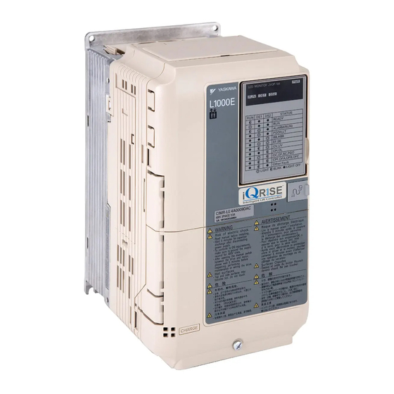
YASKAWA AC Drive-L1000E
AC Drive for Elevator Applications
Quick Start Guide
Type: CIMR-LE A
Models: 200 V Class: 3.7 to 110 kW (5 to 150 HP)
400 V Class: 4.0 to 132 kW (5 to 175 HP)
To properly use the product, read this manual thoroughly and retain
for easy reference, inspection, and maintenance. Ensure the end user
receives this manual.
MANUAL NO. TOEP YAIL1E 01A
L E
D M
O N
IT O
R JV
R U
O P
N
-1 8
4
D S
1
D S
2
P W
R
R U
N
D S
1
D S
2
R E
S T
A D
A T
Y
U S
R U
N
A L
A R
M (R
P G
O H
U N
B B
,L T
)
,H B
E F
B
,S E
O V
,U V
O H
,O
O C
L
,G F
C P
,S C
:L IG
F ,O
,P G
H T
O th
F A
O
,O F
e r
B ,O
:B L
F a
IN
u lt
F C
K
:L IG
H T
O F
F
1
Receiving
2
Mechanical Installation
3
Electrical Installation
4
Start-Up Programming &
Operation
5
Troubleshooting
Periodic Inspection &
6
Maintenance
7
Option Card Installation
A
Specifications
B
Parameter Table
C
Standards Compliance
Advertisement
Table of Contents
Troubleshooting

Related Manuals for YASKAWA L1000E


Summary of Contents for YASKAWA L1000E
- Page 1 YASKAWA AC Drive-L1000E AC Drive for Elevator Applications Quick Start Guide Type: CIMR-LE A Models: 200 V Class: 3.7 to 110 kW (5 to 150 HP) 400 V Class: 4.0 to 132 kW (5 to 175 HP) To properly use the product, read this manual thoroughly and retain for easy reference, inspection, and maintenance.
- Page 2 Yaskawa. No patent liability is assumed with respect to the use of the information contained herein. Moreover, because Yaskawa is constantly striving to improve its high-quality products, the information contained in this manual is subject to change without notice.
-
Page 3: Quick Reference
Use drive monitors to check fans, capacitors, and other components may require maintenance. Refer to Performance Life Monitors Maintenance Monitors on page 144. Fault Display and Troubleshooting Refer to Troubleshooting on page 130. Standards Compliance Refer to UL Standards on page 219 YASKAWA TOEPYAIL1E01A YASKAWA AC Drive L1000E Quick Start Guide... - Page 4 YASKAWA TOEPYAIL1E01A YASKAWA AC Drive L1000E Quick Start Guide...
-
Page 5: Table Of Contents
Installing the Option...........149 YASKAWA TOEPYAIL1E01A YASKAWA AC Drive L1000E Quick Start Guide... - Page 6 EN81-1 Compliant Circuit with one Motor Contactor ......233 Revision History ........................234 YASKAWA TOEPYAIL1E01A YASKAWA AC Drive L1000E Quick Start Guide...
-
Page 7: Preface & General Safety
• When ordering a new copy of the manual due to damage or loss, contact your Yaskawa representative or the nearest Yaskawa sales office and provide the manual number shown on the front cover. - Page 8 Before servicing, disconnect all power to the equipment. The internal capacitor remains charged even after the power supply is turned off. After shutting off the power, wait for at least the amount of time specified on the drive before touching any components. YASKAWA TOEPYAIL1E01A YASKAWA AC Drive L1000E Quick Start Guide...
- Page 9 Do not attempt to modify or alter the drive in any way not explained in this manual. Yaskawa is not responsible for damage caused by modification of the product made by the user. Failure to comply could result in death or serious injury from operation of damaged equipment.
- Page 10 Failure to comply could result in damage to the drive and will void warranty. Yaskawa is not responsible for any modification of the product made by the user. This product must not be modified. Failure to comply could result in damage to the drive or braking circuit.
- Page 11 Yaskawa offers protective designs for drives that must be used in areas subjected to oil mist and excessive vibration. Contact Yaskawa or your Yaskawa agent for details.
- Page 12 Wiring Yaskawa recommends using ring terminals on all drive models for UL/cUL compliance. Use only the tools recommended by the terminal manufacturer for crimping. YASKAWA TOEPYAIL1E01A YASKAWA AC Drive L1000E Quick Start Guide...
- Page 13 PM motor is rotating. • Contact Yaskawa or your Yaskawa agent if you plan to use any PM motor not endorsed by Yaskawa. • When using a holding brake, release the brake prior to starting the motor. Failure to set the proper timing can result in speed loss.
- Page 14 Customers who intend to use the product described in this manual for devices or systems relating to transportation, health care, space aviation, atomic power, electric power, or in underwater applications must first contact their Yaskawa representatives or the nearest Yaskawa sales office.
-
Page 15: Receiving
PRG : 3580 Lot number O / N Serial number S / N FILE NO : E131457 IP00 PASS YASKAWA ELECTRIC CORPORATION MADE IN JAPAN Enclosure type Figure 3 Nameplate Information YASKAWA TOEPYAIL1E01A YASKAWA AC Drive L1000E Quick Start Guide... - Page 16 113.8 2A0269 75.0 (100.0) 268.8 4A0140 75.0 (100.0) 140.0 2A0354 90.0 (125.0) 353.8 4A0188 90.0 (125.0) 187.5 2A0432 110.0 (150.0) 432.5 4A0225 110.0 (150.0) 225.0 4A0260 132.0 (175.0) 260.0 Figure 4 YASKAWA TOEPYAIL1E01A YASKAWA AC Drive L1000E Quick Start Guide...
-
Page 17: Mechanical Installation
Place a temporary cover over the top of the drive during installation. Remove the temporary cover before startup, as the cover will reduce ventilation and cause the drive to overheat. YASKAWA TOEPYAIL1E01A YASKAWA AC Drive L1000E Quick Start Guide... - Page 18 :LIGHT OFF A – 50 mm (1.97 in.) minimum C – 120 mm (4.72 in.) minimum B – 30 mm (1.18 in.) minimum D – Airflow direction Figure 5 Correct Installation Spacing YASKAWA TOEPYAIL1E01A YASKAWA AC Drive L1000E Quick Start Guide...
- Page 19 When vertical suspension of the drive is required in an enclosure panel, the orientation of the eye bolts for these drive models can be easily changed by turning the eye bolts counterclockwise 90 degrees. Figure 8 CIMR-LE2A0432 and 4A0260 Figure 7 Adjusting Angle of Eye Bolts ( YASKAWA TOEPYAIL1E01A YASKAWA AC Drive L1000E Quick Start Guide...
- Page 20 (8.70) (17.10) (0.30) (3.90) (0.10) (0.10) (55.1) 37.0 2A0181 (12.80) (21.70) (11.10) (10.20) (21.10) (0.30) (4.30) (0.10) (0.10) (81.6) 38.0 2A0225 (12.80) (21.70) (11.10) (10.20) (21.10) (0.30) (4.30) (0.10) (0.10) (83.8) YASKAWA TOEPYAIL1E01A YASKAWA AC Drive L1000E Quick Start Guide...
- Page 21 (10.20) (19.50) (0.30) (4.10) (0.10) (0.10) (79.4) 41.0 4A0140 (12.80) (21.70) (11.10) (10.20) (21.10) (0.30) (4.30) (0.10) (0.10) (90.4) 42.0 4A0188 (12.80) (21.70) (11.10) (10.20) (21.10) (0.30) (4.30) (0.10) (0.10) (92.6) YASKAWA TOEPYAIL1E01A YASKAWA AC Drive L1000E Quick Start Guide...
- Page 22 Table 6 Dimensions: 400 V Class Dimensions mm (in) Weight Drive Model Figure (lbs) 4A0225 (17.70) (27.80) (13.00) (12.80) (26.80) (0.50) (5.10) (0.10) (0.10) (174.2) 4A0260 (19.70) (31.50) (13.00) (14.60) (30.40) (0.50) (5.10) (0.20) (0.20) (211.6) YASKAWA TOEPYAIL1E01A YASKAWA AC Drive L1000E Quick Start Guide...
-
Page 23: Electrical Installation
NOTICE: The minimum load for the multi-function relay output MA-MB-MC is 10 mA. If a circuit requires less than 10 mA (reference value), connect it to a photocoupler output (P1-C1, P2-C2). Improper application of peripheral devices could result in damage to the photocoupler output of the drive. YASKAWA TOEPYAIL1E01A YASKAWA AC Drive L1000E Quick Start Guide... - Page 24 <3> Set up a thermal relay sequence to disconnect drive main power in the event of an overheat condition on the dynamic braking option. <4> Self-cooling motors do not require the same wiring necessary for motors with separate cooling fans. YASKAWA TOEPYAIL1E01A YASKAWA AC Drive L1000E Quick Start Guide...
- Page 25 NOTICE: When using the automatic fault reset function with wiring designed to shut off the power supply upon drive fault, make sure the drive does not trigger a fault output during fault reset (L5-02 = 0, default). Failure to comply will prevent the automatic fault reset function from working properly. YASKAWA TOEPYAIL1E01A YASKAWA AC Drive L1000E Quick Start Guide...
-
Page 26: Main Circuit Connection Diagram
Y E A _ – – c o m - c o m - 24 V Control Control Gate board Operator Power Gate board Operator board board Supply Figure 9 Drive Main Circuit Configurations YASKAWA TOEPYAIL1E01A YASKAWA AC Drive L1000E Quick Start Guide... -
Page 27: Terminal Cover
Note: The shape of the terminal covers and the numbers of screws differ depending on the drive models. Figure 12 YEA_common Figure 12 Removing the Terminal Cover YASKAWA TOEPYAIL1E01A YASKAWA AC Drive L1000E Quick Start Guide... - Page 28 Wiring the Control Circuit Terminal on page 46 for details on wiring. Figure 15 YEA_common Connect ground wiring first, followed by the main circuit, and then wire the control circuit. Figure 15 Reattaching the Terminal Cover YASKAWA TOEPYAIL1E01A YASKAWA AC Drive L1000E Quick Start Guide...
-
Page 29: Led Monitor And
4A0030, and 4A0039 do not use a screw to affix the front cover). Pinch inwards on the tabs found on each side of the front cover, then pull forward to remove it from the drive. Figure 18 YEA_commo Figure 18 Remove the Front Cover (Models 2A0018 to 2A0094 and 4A0009 to 4A0049) YASKAWA TOEPYAIL1E01A YASKAWA AC Drive L1000E Quick Start Guide... - Page 30 Pinch inwards on the hooks found on each side of the front cover while guiding it back into the drive. Make sure it clicks firmly into place. YASKAWA TOEPYAIL1E01A YASKAWA AC Drive L1000E Quick Start Guide...
- Page 31 Figure 21 Figure 21 Reattach the Front Cover (2A0106 to 2A0432 and 4A0056 to 4A0260) After connecting the hooks to the drive, press firmly on the cover to lock it into place. YASKAWA TOEPYAIL1E01A YASKAWA AC Drive L1000E Quick Start Guide...
-
Page 32: Main Circuit Wiring
For 400 V class: 10 Ω or less Note: Use terminal B1 and - when installing the braking unit (CDBR type) to the drives with built-in braking transistor (2A0018 to 2A0144, 4A0009 to 4A0075). YASKAWA TOEPYAIL1E01A YASKAWA AC Drive L1000E Quick Start Guide... - Page 33 Closed-Loop Crimp Terminal Size on page 226 for closed-loop crimp terminal recommendations. The wire gauges listed in the following tables are Yaskawa recommendations. Refer to local codes for proper wire gauge selections. YASKAWA TOEPYAIL1E01A YASKAWA AC Drive L1000E Quick Start Guide...
- Page 34 – (6 to 4) 6.0 to 10 2 to 2.5 B1, B2 – (10 to 6) (17.7 to 22.1) 10 to 16 4 to 6 (8 to 6) (35.4 to 53.1) YASKAWA TOEPYAIL1E01A YASKAWA AC Drive L1000E Quick Start Guide...
- Page 35 (1/0 to 4/0) 50 to 95 18 to 23 2A0181 –, +1 – (1 to 4/0) (159 to 204) 70 to 95 – (1/0 to 4/0) 25 to 35 (4 to 2) YASKAWA TOEPYAIL1E01A YASKAWA AC Drive L1000E Quick Start Guide...
- Page 36 Note: When connecting peripheral devices and options to the terminals –, +1, +3, B1, and B2, refer to the instruction manuals for each device. For more information, contact Yaskawa or your nearest sales representative. YASKAWA TOEPYAIL1E01A YASKAWA AC Drive L1000E Quick Start Guide...
- Page 37 – (10 to 6) 6.0 to 10 2.7 to 3.0 B1, B2 – (10 to 8) (23.9 to 26.6) 6.0 to 10 4 to 6 (10 to 8) (35.4 to 53.1) YASKAWA TOEPYAIL1E01A YASKAWA AC Drive L1000E Quick Start Guide...
- Page 38 (6 to 250) 25 to 50 9 to 11 4A0094 –, +1 – (3 to 1/0) (79.7 to 97.4) 16 to 50 – (6 to 1/0) 16 to 25 (6 to 4) YASKAWA TOEPYAIL1E01A YASKAWA AC Drive L1000E Quick Start Guide...
- Page 39 Note: When connecting peripheral devices and options to the terminals –, +1, +3, B1, and B2, refer to the instruction manuals for each device. For more information, contact Yaskawa or your nearest sales representative. YASKAWA TOEPYAIL1E01A YASKAWA AC Drive L1000E Quick Start Guide...
- Page 40 NOTICE: Before applying power to the drive, use power-off resistance checks to check for short-circuits between (R/L1, S/L2, and T/L3) or between main circuit terminals and ground. Failure to comply may result in damage to the drive. YASKAWA TOEPYAIL1E01A YASKAWA AC Drive L1000E Quick Start Guide...
- Page 41 Refer to Figure 22 when using multiple drives. Do not loop the ground wire. Figure 22 Not OK Figure 22 Multiple Drive Wiring YASKAWA TOEPYAIL1E01A YASKAWA AC Drive L1000E Quick Start Guide...
- Page 42 Note: Do not solder the ends of wire connections to the drive. Soldered wiring connections can loosen over time. Improper wiring practices could result in drive malfunction due to loose terminal connections. YASKAWA TOEPYAIL1E01A YASKAWA AC Drive L1000E Quick Start Guide...
- Page 43 <1> Setting jumper S3 for an external power supply makes the wire jumper between terminals H1, H2, and HC ineffective. Remove the wire jumper and connect an external power supply that can supply terminals H1, H2, and HC continuously. YASKAWA TOEPYAIL1E01A YASKAWA AC Drive L1000E Quick Start Guide...
- Page 44 <1> Communications output (-) 115.2 kbps (max.) Shield ground <1> Enable the termination resistor in the last drive in a MEMOBUS network by setting DIP switch S2 to the ON position. YASKAWA TOEPYAIL1E01A YASKAWA AC Drive L1000E Quick Start Guide...
- Page 45 MC, M1, M2, HC, (1.9 to 2.2) Solid wire: (18) (24 to 20) (20) etc. H1, H2, DM+, 0.25 to 1.5 DM-, IG, R+, R-, (24 to 16) S+, S-, RP, MP, E YASKAWA TOEPYAIL1E01A YASKAWA AC Drive L1000E Quick Start Guide...
- Page 46 3 Electrical Installation Ferrule-Type Wire Terminals Yaskawa recommends using CRIMPFOX 6, a crimping tool manufactured by PHOENIX CONTACT, to prepare wire ends with insulated sleeves before connecting to the drive. Refer to Table 15 for dimensions. Figure 26 YEA_common Figure 26 Ferrule Dimensions...
- Page 47 NOTICE: Do not exceed 50 meters (164 ft.) for the control line between the drive and the operator when using an analog signal from a remote source to supply the frequency reference. Failure to comply could result in poor system performance. YASKAWA TOEPYAIL1E01A YASKAWA AC Drive L1000E Quick Start Guide...
- Page 48 Control I/O Configuration on page 49 for setting instructions. Figure 29 YEA_ com- Jumper S3 Terminal H1/H2 Sink/Source Sel. DIP Switch S2 RS-422/485 Termination Resistor Figure 29 Locations of Jumpers and Switches on the Terminal Board YASKAWA TOEPYAIL1E01A YASKAWA AC Drive L1000E Quick Start Guide...
-
Page 49: Control I/O Configuration
Drive Internal Power Supply External 24 Vdc Power Supply (Terminal SN and SP) Sinking Mode (NPN) 24 Vdc 24 Vdc External 24 Vdc Sourcing Mode (PNP) 24 Vdc 24 Vdc External 24 Vdc YASKAWA TOEPYAIL1E01A YASKAWA AC Drive L1000E Quick Start Guide... -
Page 50: Connect To A Pc
The drive can connect to a USB port on a PC using a USB 2.0, AB-type cable (sold separately). After connecting the drive to a PC, Yaskawa DriveWizard Plus software can be used to monitor drive performance and manage parameter settings. -
Page 51: Wiring Checklist
Properly separate control circuit wiring and main circuit wiring. – Analog signal line wiring should not exceed 50 m (164 ft.). – Safe Disable input wiring should not exceed 30 m (98 ft.). – YASKAWA TOEPYAIL1E01A YASKAWA AC Drive L1000E Quick Start Guide... -
Page 52: Start-Up Programming
Figure 33 POWER Figure 33 Alarm LED Fault Figure 34 shows the LED display when an oV or UV fault has occurred. Figure 34 POWER Figure 34 Fault LED YASKAWA TOEPYAIL1E01A YASKAWA AC Drive L1000E Quick Start Guide... -
Page 53: Digital Operator Jvop-180 Keys And Displays
Lit while the operator is selected to run the drive (LOCAL mode). Refer to page LO/RE Light for details. ALM LED Light Refer to ALARM (ALM) LED Displays on page YASKAWA TOEPYAIL1E01A YASKAWA AC Drive L1000E Quick Start Guide... - Page 54 Function Key 1 (F1) HOME Pressing returns to the top menu (Speed Reference). Pressing returns to the previous display. During Up command FWD/REV During Down command YASKAWA TOEPYAIL1E01A YASKAWA AC Drive L1000E Quick Start Guide...
- Page 55 - MODE - Fault Possible Solutions on page 130 for more information and possible solutions. ALM c o m - Ext Fault S3 LED is lit and DRV displayed. RESET External fault (example) YASKAWA TOEPYAIL1E01A YASKAWA AC Drive L1000E Quick Start Guide...
- Page 56 STOP key was pushed. Examples <1> Refer to Figure 37 for the difference between “flashing” and “flashing quickly”. Figure 37 common_ Flashing Flashing quickly Figure 37 RUN LED Status and Meaning YASKAWA TOEPYAIL1E01A YASKAWA AC Drive L1000E Quick Start Guide...
- Page 57 <5> The Speed Reference appears after the initial display which shows the product name. <6> The information that appears on the display will vary depending on the drive. YASKAWA TOEPYAIL1E01A YASKAWA AC Drive L1000E Quick Start Guide...
-
Page 58: The Drive And Programming Modes
“1” flashes. C1-02=001.50 sec (0.0~600.00) “1.50 sec” left right ← → -PRMSET- Decel Ramp 1 C1-02=002.50 sec Press and enter 0020.0. (0.0~600.00) “1.50 sec” ← → YASKAWA TOEPYAIL1E01A YASKAWA AC Drive L1000E Quick Start Guide... - Page 59 (0.0~600.00) “1.50 sec” - MODE - Speed Ref (OPR) U1-01= 0.00% 12. Press as many times as necessary to return to the initial display. U1-02= 0.00% RSEQ U1-03= 0.00A LREF FWD/REV YASKAWA TOEPYAIL1E01A YASKAWA AC Drive L1000E Quick Start Guide...
- Page 60 <1> Use the up and down arrow keys to scroll through the Setup Group. Press the ENTER key to view or change parameter settings. <2> To return to the previous menu without saving changes, press the ESC key. Figure 40 Setup Group Example YASKAWA TOEPYAIL1E01A YASKAWA AC Drive L1000E Quick Start Guide...
-
Page 61: Start-Up Flowcharts
Auto-Tuning. Flowchart Purpose Page Installation, wiring, and basic steps required to setup the motor and elevator for operation Auto-Tuning for induction motors Auto-Tuning for PM motors Encoder Offset Auto-Tuning YASKAWA TOEPYAIL1E01A YASKAWA AC Drive L1000E Quick Start Guide... - Page 62 • Adjust speed control loop (C5- ) etc. FINISH Figure 41 Installation, Wiring, Basic Setup for Motor and Elevator Note: Set parameter H5-11 to 1 when setting parameters using MEMOBUS/Modbus communications. YASKAWA TOEPYAIL1E01A YASKAWA AC Drive L1000E Quick Start Guide...
- Page 63 EnDat 2.2/01, or EnDat 2.2/22 encoder Permanent magnet motor with ERN1387 or Closed Loop Vector Control for PM motors PG-E3 ERN487 encoder Yaskawa IPM motor with incremental encoder Closed Loop Vector Control for PM motors PG-X3 YASKAWA TOEPYAIL1E01A YASKAWA AC Drive L1000E Quick Start Guide...
- Page 64 If the value in U1-05 is negative, alter the setting of parameter F1-05. Note: Always set the motor rotation direction prior to the encoder rotation direction. Refer to Motor Rotation Direction Setup on page YASKAWA TOEPYAIL1E01A YASKAWA AC Drive L1000E Quick Start Guide...
- Page 65 FINISH <1> If an LED operator is used, the display shows “ ”. <2> If an LED operator is used, the display shows “ ”. Figure 42 Auto-Tuning for Induction Motors YASKAWA TOEPYAIL1E01A YASKAWA AC Drive L1000E Quick Start Guide...
- Page 66 FINISH <1> If an LED operator is used, the display shows “ ”. <2> If an LED operator is used, the display shows “ ”. Figure 43 Auto-Tuning for PM Motors YASKAWA TOEPYAIL1E01A YASKAWA AC Drive L1000E Quick Start Guide...
- Page 67 FINISH <1> If an LED operator is used, the display shows “ ”. <2> If an LED operator is used, the display shows “ ”. Figure 44 PG Encoder Offset Auto-Tuning YASKAWA TOEPYAIL1E01A YASKAWA AC Drive L1000E Quick Start Guide...
- Page 68 <1> Auto-Tuning of PG-E3 encoder characteristics requires a PG-E3 option with software version 1102 or later. To identify the PG-E3 software version, refer to the PG-E3 labeling on the option, in the field designated “C/N” (S + four digit number). YASKAWA TOEPYAIL1E01A YASKAWA AC Drive L1000E Quick Start Guide...
- Page 69 PM motor. This type of Auto-Tuning automatically sets the characteristics of the PG-E3 option card for the ERN1387 encoder in parameters F1-66 to F1-81 (Encoder Adjust 1 to 16). YASKAWA TOEPYAIL1E01A YASKAWA AC Drive L1000E Quick Start Guide...
- Page 70 The display automatically returns to the display shown in Step 3. ∗0∗ T1-01= 0 Standard Tuning DATA Enter Data from the Motor Nameplate After selecting the type of Auto-Tuning, enter the data required from the motor nameplate. YASKAWA TOEPYAIL1E01A YASKAWA AC Drive L1000E Quick Start Guide...
- Page 71 • T1-04, Motor Rated Current • T1-05, Motor Base Frequency • T1-06, Number of Motor Poles - A.TUNE - • T1-07, Motor Base Speed Rated Speed T1-07= 1450RPM (0 ~ 24000) “1450RPM” DATA YASKAWA TOEPYAIL1E01A YASKAWA AC Drive L1000E Quick Start Guide...
- Page 72 T1-02: Motor Rated Power Sets the motor rated power according to the motor nameplate value. Parameter Name Setting Range Default T1-02 Motor Rated Power 0.00 to 650.00 kW Determined by o2-04 YASKAWA TOEPYAIL1E01A YASKAWA AC Drive L1000E Quick Start Guide...
- Page 73 Sets the number of pulses from the PG encoder. Set the actual number of pulses for one full motor rotation. Parameter Name Setting Range Default T1-08 PG Number of Pulses Per Revolution 0 to 60000 ppr 1024 ppr Note: T1-08 will only be displayed in CLV. YASKAWA TOEPYAIL1E01A YASKAWA AC Drive L1000E Quick Start Guide...
- Page 74 T1-10: Motor Rated Slip Sets the rated slip for the motor. The default setting displayed is the motor rated slip for a Yaskawa motor calculated from the output power set in T1-02. Enter the data listed on the motor test report.
- Page 75 Note: If T2-13 is set to 0, then the drive will use E5-24 (Motor Induction Voltage Constant 2), and will automatically set E5-09 (Motor Induction Voltage Constant 1) to 0.0. If T2-13 is set to 1, then the drive will use E5-09 and will automatically set E5-24 to 0.0. YASKAWA TOEPYAIL1E01A YASKAWA AC Drive L1000E Quick Start Guide...
- Page 76 Sets the direction of motor rotation for execution of Auto-Tuning of PG-E3 encoder characteristics (T2-01 = 12). Parameter Name Setting Range Default T2-19 Rotation Direction for Auto-Tuning of PG-E3 Encoder Characteristic 0, 1 Setting 0: Forward (Up) Setting 1: Reverse (Down) YASKAWA TOEPYAIL1E01A YASKAWA AC Drive L1000E Quick Start Guide...
-
Page 77: Setup Procedure For Elevator Applications
• An Up or Down Signal must be set at the source specified in b1-02. • If a multifunction input is programmed for output contactor feedback (H1- =56), then the output contactor must be closed. YASKAWA TOEPYAIL1E01A YASKAWA AC Drive L1000E Quick Start Guide... - Page 78 (d1-03 or terminal A1, A2 input value if H3-02 or H3-10 is set to 3) Speed reference 4 (d1-04) Speed reference 5 (d1-05) Speed reference 6 (d1-06) Speed reference 7 (d1-07) Speed reference 8 (d1-08) 0 = Off, 1 = On YASKAWA TOEPYAIL1E01A YASKAWA AC Drive L1000E Quick Start Guide...
- Page 79 DC Injection/ Position lock Position lock Speed Safe disable (terminals H1/H2 on) and Baseblock off (H1- = 8/9) Up/Down Command Leveling speed Selected speed (other than leveling) Input is set No effect YASKAWA TOEPYAIL1E01A YASKAWA AC Drive L1000E Quick Start Guide...
- Page 80 H2: Multi-Function Digital Outputs on page 183. Multi-Function Analog Inputs The H3 parameters assign functions to analog input terminals A1 and A2 analog input functions, refer to H3: Multi- Function Analog Inputs on page 186. YASKAWA TOEPYAIL1E01A YASKAWA AC Drive L1000E Quick Start Guide...
- Page 81 Safe disable (terminals H1/H2 on) or Baseblock off (H1- = 8/9) = 51 (Output Cont. Contr.) = 50 (Brake Control) Enabled Figure 47 With Up/Down command cleared and U1-05 ≥ S1-26 YASKAWA TOEPYAIL1E01A YASKAWA AC Drive L1000E Quick Start Guide...
- Page 82 51) are cleared. • If C1-15 > 0.00, the drive decelerates to stop at the rate set to C1-15, then applies the brake, shuts the output off, and opens the motor contactor. YASKAWA TOEPYAIL1E01A YASKAWA AC Drive L1000E Quick Start Guide...
- Page 83 (H2- = 51) Motor Contactor Response (H1- = 56) Brake Control (H2- = 50) Enabled Figure 50 Brake Sequence without Torque Compensation at Start Figure 50 is divided into time zones. YASKAWA TOEPYAIL1E01A YASKAWA AC Drive L1000E Quick Start Guide...
- Page 84 Baseblock off (H1- = 8/9) Output Contactor Control (H2- = 51) Motor Contactor Response (H1- = 56) Brake Control (H2- = 50) Enabled Figure 51 Brake Sequence Using Torque Compensation at Start YASKAWA TOEPYAIL1E01A YASKAWA AC Drive L1000E Quick Start Guide...
- Page 85 This can be done by bringing the elevator into two different load conditions and teaching the corresponding analog input value and torque reference value to the drive. Note: 1. This torque compensation requires a closed loop control mode (CLV, CLV/PM). 2. The torque compensation value is limited to 120%. YASKAWA TOEPYAIL1E01A YASKAWA AC Drive L1000E Quick Start Guide...
- Page 86 Load Sensor (Torque Compensation Value with Load Condition 2) with Load Condition 1) During Load Condition 1 Figure 52 Torque Compensation at start for the Elevator in Up and Down Direction YASKAWA TOEPYAIL1E01A YASKAWA AC Drive L1000E Quick Start Guide...
- Page 87 Load Sensor with Load Condition 2) S3-27 (Torque Compensation Value During Load Condition 1 with Load Condition 1) Figure 53 Torque Compensation at Start for the Elevator in Up and Down Direction YASKAWA TOEPYAIL1E01A YASKAWA AC Drive L1000E Quick Start Guide...
-
Page 88: S: Elevator Parameters
Position Lock should be performed. A setting of 0.00 disables S1-05. Parameter Name Setting Range Default S1-05 DC Injection / Position Lock Time at Stop 0.00 to 10.00 s 0.60 s YASKAWA TOEPYAIL1E01A YASKAWA AC Drive L1000E Quick Start Guide... - Page 89 Auto-Tuning. When using setting S1-12 = 1 or 2, ensure that the multi-function output terminals are properly wired and in the correct state before setting parameter S1-12. Failure to comply could result in damage to the drive, serious injury or death. YASKAWA TOEPYAIL1E01A YASKAWA AC Drive L1000E Quick Start Guide...
- Page 90 Sets the filter time constant applied to the torque signal used for the slip compensation value calculation. Parameter Name Setting Range Default S2-06 Slip Compensation Torque Detection Filter Time Constant 0 to 2000 ms 500 ms YASKAWA TOEPYAIL1E01A YASKAWA AC Drive L1000E Quick Start Guide...
- Page 91 Adds a bias to torque compensation in the Down direction. Refer to Adjusting the Torque Compensation at Start on page 85 for details. Parameter Name Setting Range Default S3-12 Starting Torque Compensation Bias in Down Direction –40.0 to 40.0% 0.00% YASKAWA TOEPYAIL1E01A YASKAWA AC Drive L1000E Quick Start Guide...
- Page 92 The Dwell 2 function will end when the drive reaches this speed. A setting of 0.00 will disable the acceleration rate switch that occurs at the end of Dwell 2. Parameter Name Setting Range Default S3-21 Dwell 2 End Speed 0.00 to 100.00% 0.00% YASKAWA TOEPYAIL1E01A YASKAWA AC Drive L1000E Quick Start Guide...
- Page 93 Sets an intermediary value for the torque bias used for Anti-Rollback when Position Lock at start is performed. This setting rarely needs to be changed. Parameter Name Setting Range Default S3-34 Anti-Rollback Torque Bias 1 0.0 to 100.0% 0.0% YASKAWA TOEPYAIL1E01A YASKAWA AC Drive L1000E Quick Start Guide...
- Page 94 If the motor rotation (i.e., car movement) is below the movement detection level set to S3-40, the drive will reduce the Anti-Rollback gain according to the gain reduction level set in S3-41. Parameter Name Setting Range Default S3-41 Position Lock Gain at Start 2 Reduction 0.00 to 1.00 0.50 YASKAWA TOEPYAIL1E01A YASKAWA AC Drive L1000E Quick Start Guide...
- Page 95 Specifies the type of backup power supply the drive should switch to when the power goes out. Parameter Name Setting Range Default S4-06 Rescue Operation Power Supply Selection 0 to 2 Setting 0: Battery Setting 1: UPS (single-phase) Setting 2: UPS (three-phase) YASKAWA TOEPYAIL1E01A YASKAWA AC Drive L1000E Quick Start Guide...
- Page 96 Speed Reference Selection for Rescue Operation 0, 1 Setting 0: The setting of parameter d1-25 is used as speed reference for Rescue Operation Setting 1: The speed selected by digital inputs is used as speed reference YASKAWA TOEPYAIL1E01A YASKAWA AC Drive L1000E Quick Start Guide...
- Page 97 (H1- = 53). Advance Short Floor calculates optimal speed based on the Short Floor Minimum Constant Speed Time (S5-03) and the currently selected deceleration rate. YASKAWA TOEPYAIL1E01A YASKAWA AC Drive L1000E Quick Start Guide...
- Page 98 <1> The drive will recognize the speed reference that is lower than the Leveling Speed Detection Level (d1-28) as the leveling speed if the speed priority is set for multi-step speed reference (d1-18 = 0 or 3). YASKAWA TOEPYAIL1E01A YASKAWA AC Drive L1000E Quick Start Guide...
- Page 99 Distance Calculation Deceleration Time Gain 50.0 to 200.0% 150.0% Note: Setting S5-05 too low may trigger an overrun due to faster optimum speeds and shortened leveling times. Avoid setting this gain less than 100%. YASKAWA TOEPYAIL1E01A YASKAWA AC Drive L1000E Quick Start Guide...
- Page 100 The Up/Down command is not active, the speed reference is 0, or the leveling speed reference has been selected by one of the multi-function input terminals (H1- Leveling speed reference has priority (d1-18 = 2) YASKAWA TOEPYAIL1E01A YASKAWA AC Drive L1000E Quick Start Guide...
- Page 101 (H1- = 50). Multi-step speed sequence = 50 to 53 are open. (d1-18 = 2) Rated speed reference is not selected Up/Down command is not active. ≠ 50). (H1- YASKAWA TOEPYAIL1E01A YASKAWA AC Drive L1000E Quick Start Guide...
- Page 102 Default S5-12 Stop Distance 0 to 10000 mm 0 mm <1> <1> The setting range becomes 0.00 to 393.00 inches when the length units are set for inches (o1-12 = 1). YASKAWA TOEPYAIL1E01A YASKAWA AC Drive L1000E Quick Start Guide...
- Page 103 = 50) and an input terminal set for “Brake feedback” (H1- = 79) do not match for the time set to S6-05. Parameter Name Setting Range Default S6-05 Brake Response Error (SE4) Detection Time 0 to 10000 ms 500 ms YASKAWA TOEPYAIL1E01A YASKAWA AC Drive L1000E Quick Start Guide...
- Page 104 Restart when the Up/Down command is still active while the Baseblock or Safe Torque-Off state is left. To use this function with the Safe Disable function, parameter L8-88 must be set to 1. YASKAWA TOEPYAIL1E01A YASKAWA AC Drive L1000E Quick Start Guide...
- Page 105 200 V and 400 V class drives: 24 Vdc Magnet Pole Search Auto-Tuning. Absolute PG Encoder with PG-F3 200 V class drives: 48 to 340 Vdc or PG-E3 option card 400 V class drives: 96 to 680 Vdc YASKAWA TOEPYAIL1E01A YASKAWA AC Drive L1000E Quick Start Guide...
- Page 106 Select the configuration that matches your application. Follow the corresponding instructions for wiring and drive settings. For configurations not covered in the list above, contact your Yaskawa representative or our sales office directly for consultation. YASKAWA TOEPYAIL1E01A YASKAWA AC Drive L1000E Quick Start Guide...
- Page 107 Power supply circuit CN19 to S = 55 (Rescue Operation) Magnetic Contactor Sequence Magnetic Contactor B Magnetic Contactor A = 55 (Rescue Operation) Figure 58 Using a Single-Phase 230 V UPS YASKAWA TOEPYAIL1E01A YASKAWA AC Drive L1000E Quick Start Guide...
- Page 108 (CN19). Alternatively use a 24 Vdc battery and an optional 24 V Backup Power Supply Unit. • Enable Light Load Direction Search (S4-01 = 1). YASKAWA TOEPYAIL1E01A YASKAWA AC Drive L1000E Quick Start Guide...
- Page 109 After the car has stopped, open contactors A and C. Clear the input terminal set for Rescue Operation (H1- = 55). Wait at least 0.5 s and then close contactor B to return to operation with normal power supply. YASKAWA TOEPYAIL1E01A YASKAWA AC Drive L1000E Quick Start Guide...
- Page 110 <1> Install the inrush current suppression circuit outside the drive if the DC bus battery voltage is lower than 190 Vdc for 200 V class drives and 380 Vdc for 400 V class drives. Failure to comply will cause the soft-charge bypass relay to remain open and result in damage to the drive. YASKAWA TOEPYAIL1E01A YASKAWA AC Drive L1000E Quick Start Guide...
- Page 111 Motor rated power (kW) × Operation frequency when running battery (Hz) × 2 × 1000 Y E A _ c o m Load current of battery (A) = Battery voltage (Vdc) × 0.6 (Motor efficiency) × Motor rated frequency (Hz) YASKAWA TOEPYAIL1E01A YASKAWA AC Drive L1000E Quick Start Guide...
- Page 112 Magnetic Contactor A Magnetic Contactor C = 55 (Rescue Operation) Figure 61 Voltage Lower Than 190 to 340 Vdc for 200 V Class Drives, 380 to 680 Vdc for 400 V Class Drives YASKAWA TOEPYAIL1E01A YASKAWA AC Drive L1000E Quick Start Guide...
- Page 113 The main circuit battery voltage must be higher than 48 Vdc for 200 V and 400 V class drives. Yaskawa offers a 24 V Power Supply Option for the control circuit that is useful in applications unable to connect to a backup battery greater than 250 V.
- Page 114 380 Vdc for 400 V class drives. Failure to comply will cause the soft-charge bypass relay to remain open and result in damage to the drive. Refer to Table 31 for the installation of the inrush current suppression circuit for battery. YASKAWA TOEPYAIL1E01A YASKAWA AC Drive L1000E Quick Start Guide...
- Page 115 Magnetic Contactor A Magnetic Contactor C = 55 (Rescue Operation) Figure 64 Voltage Lower Than 190 to 340 Vdc for 200 V Class Drives, 380 to 680 Vdc for 400 V Class Drives YASKAWA TOEPYAIL1E01A YASKAWA AC Drive L1000E Quick Start Guide...
- Page 116 Ending Rescue Operation After the car has stopped, open contactor A. Clear the input terminal set for Rescue Operation (H1- = 55). Close contactor B to return to operation with normal power supply. YASKAWA TOEPYAIL1E01A YASKAWA AC Drive L1000E Quick Start Guide...
- Page 117 NOTICE: Be sure that the connector fastens at the correct angle to the drive port. The incorrect angle could damage the battery, cable, or connector. Figure 60 Port CN19 Press in on the connector clip to plug in the cable. Figure 67 Connecting the Cable YASKAWA TOEPYAIL1E01A YASKAWA AC Drive L1000E Quick Start Guide...
- Page 118 NOTICE: Make sure the cable does not get pinched between the drive and the connector cover, as this could damage the cable. Figure 62 Figure 69 Reattaching the Connector Cover (2) Figure 63 Connect to battery. Figure 70 Drive and Battery Connection Complete YASKAWA TOEPYAIL1E01A YASKAWA AC Drive L1000E Quick Start Guide...
- Page 119 Insert a straight-edge screwdriver into the opening as shown in Figure 73, then remove the CN19 connector cover by sliding it as shown in Figure Figure 66 Figure 73 Removing the CN19 Connector Cover YASKAWA TOEPYAIL1E01A YASKAWA AC Drive L1000E Quick Start Guide...
- Page 120 NOTICE: Make sure the cable does not get pinched between the drive and the CN19 connector cover, as this could damage the cable. Figure 69 Downward Leftward Figure 76 Sliding the CN19 Connector Cover into Place YASKAWA TOEPYAIL1E01A YASKAWA AC Drive L1000E Quick Start Guide...
- Page 121 S4-03. It then compares the load condition of both operations and travels to the next floor using the lighter load condition direction. The speed reference used for Light Load Direction Search can be set in parameter S4-04. YASKAWA TOEPYAIL1E01A YASKAWA AC Drive L1000E Quick Start Guide...
- Page 122 Elevator moves in the direction of the light load Off (open) = 55 On (closed) Light Load Direction Search status Off (open) = 54 Light load direction Figure 80 Light Load Direction Detection (Down) YASKAWA TOEPYAIL1E01A YASKAWA AC Drive L1000E Quick Start Guide...
-
Page 123: Setup Troubleshooting And Possible Solutions
• Set a new password to parameter A1-05. • Check the drive main input voltage by looking at the DC bus voltage (U1-07). Undervoltage was detected. • Check all main circuit wiring. YASKAWA TOEPYAIL1E01A YASKAWA AC Drive L1000E Quick Start Guide... - Page 124 64 PG Encoder Setup on page Drive control circuit terminals for the Up and Down • Check the control circuit wiring. commands are switched. • Correct any fault wiring. YASKAWA TOEPYAIL1E01A YASKAWA AC Drive L1000E Quick Start Guide...
- Page 125 • Place the wiring inside a metal conduit to shield it from switching noise. noise. • Ground the drive and motor properly. • Separate the main circuit wiring and the control lines. • Make sure wires and the motor have been properly grounded. YASKAWA TOEPYAIL1E01A YASKAWA AC Drive L1000E Quick Start Guide...
- Page 126 (C5-13 and C5-14). Rollback occurs before the brake applies at stop. • Increase the Position Lock Gain at Stop S3-03 gradually CLV/PM until no rollback occurs. If vibration occurs reduce the gain S3-03. YASKAWA TOEPYAIL1E01A YASKAWA AC Drive L1000E Quick Start Guide...
- Page 127 Speed control loop adjusted with too much gain. occurs at speed lower than C5-07. CLV/PM • Decrease C5-13 and then increase C5-14 if the problem occurs at speed lower than C5-07 but only during deceleration. YASKAWA TOEPYAIL1E01A YASKAWA AC Drive L1000E Quick Start Guide...
- Page 128 Increase the Carrier Frequency in parameter C6-03. If the acoustic noise from The carrier frequency is too low. carrier frequency is set higher than the default setting, a the motor. current derating must be considered. YASKAWA TOEPYAIL1E01A YASKAWA AC Drive L1000E Quick Start Guide...
- Page 129 4 Start-Up Programming YASKAWA TOEPYAIL1E01A YASKAWA AC Drive L1000E Quick Start Guide...
-
Page 130: Troubleshooting
The drive capacity cannot be detected correctly (drive capacity is checked when the drive is powered up). Terminal Board not Connected CPF25 Control Circuit Error CPF26 to CPF34 CPU error A/D Conversion Error CPF35 An A/D conversion error or control circuit error occurred. YASKAWA TOEPYAIL1E01A YASKAWA AC Drive L1000E Quick Start Guide... - Page 131 Output Current Imbalance (detected when L8-29 = 1) One or more of the phases in the output current is lost. Overcurrent Drive sensors have detected an output current greater than the specified overcurrent level. YASKAWA TOEPYAIL1E01A YASKAWA AC Drive L1000E Quick Start Guide...
- Page 132 Motor Overheat Fault (PTC thermistor input) • The motor overheat signal to analog input terminal A1 or A2 exceeded the fault detection level. • Detection requires that multi-function analog input H3-02 or H3-10 = “E”. YASKAWA TOEPYAIL1E01A YASKAWA AC Drive L1000E Quick Start Guide...
- Page 133 Motor pull out or step out has occurred. Motor has exceeded its pull out torque. Undertorque Detection 1 The current has fallen below the minimum value set for torque detection (L6-02) for longer than the allowable time (L6-03). YASKAWA TOEPYAIL1E01A YASKAWA AC Drive L1000E Quick Start Guide...
-
Page 134: Alarm Detection
F1-11. Up/Down Command Error Both forward run and reverse run closed simultaneously for over 0.5 s. Option Card External Fault An external fault condition is present. YASKAWA TOEPYAIL1E01A YASKAWA AC Drive L1000E Quick Start Guide... - Page 135 For 400 V class: approximately 820 V PASS MEMOBUS/Modbus Communication Test Mode Complete Encoder Disconnected (for Control Mode with Encoder) Detected when no encoder signal is received for a time longer than setting in F1-14. YASKAWA TOEPYAIL1E01A YASKAWA AC Drive L1000E Quick Start Guide...
- Page 136 • Low voltage in the control drive input power. This alarm outputs only if L2-01 is not 0 and DC bus voltage is under L2-05. Output Voltage Detection Error There is a problem with the output voltage. YASKAWA TOEPYAIL1E01A YASKAWA AC Drive L1000E Quick Start Guide...
-
Page 137: Operator Programming Errors
• Parameters that control Online Tuning are not set correctly. PG-F3 Setting Error oPE20 The encoder signal frequency is too high. Elevator Parameter Setting Fault oPE21 Elevator parameters are not set correctly. YASKAWA TOEPYAIL1E01A YASKAWA AC Drive L1000E Quick Start Guide... -
Page 138: Auto-Tuning Fault Detection
Er-19 Inductance Error Er-20 Stator Resistance Error Er-21 Z Pulse Correction Error Er-22 Initial Rotor Pole Search Error Er-23 Non-rotating Encoder Offset Tuning Warning Er-24 Auto-Tuning Error for PG-E3 Encoder Characteristics YASKAWA TOEPYAIL1E01A YASKAWA AC Drive L1000E Quick Start Guide... -
Page 139: Copy Function Related Displays
Reading Parameter Settings (flashing) vAEr Voltage Class, Capacity Mismatch vFyE Parameter settings in the drive and those saved to the copy function are not the same vrFy Comparing Parameter Settings (flashing) YASKAWA TOEPYAIL1E01A YASKAWA AC Drive L1000E Quick Start Guide... - Page 140 Reapply power after the digital operator display is out. Note: If the Up/Down command is present, the drive will disregard any attempts to reset the fault. Remove the Up/Down command before attempting to clear a fault situation. YASKAWA TOEPYAIL1E01A YASKAWA AC Drive L1000E Quick Start Guide...
-
Page 141: Periodic Inspection & Maintenance
Recommended Daily Inspection ■ Table 37 outlines the recommended daily inspection for Yaskawa drives. Check the following items on a daily basis to avoid premature deterioration in performance or product failure. Copy this checklist and mark the “Checked” column after each inspection. - Page 142 Recommended Periodic Inspection Table 38 outlines the recommended periodic inspections for Yaskawa drive installations. Although periodic inspections should generally be performed once a year, the drive may require more frequent inspection in harsh environments or with rigorous use. Operating and environmental conditions, along with experience in each application, will determine the actual inspection frequency for each installation.
-
Page 143: Periodic Maintenance
• Cooling Fan, Circulation Fan, Control Board Cooling Fan • Electrolytic Capacitors • Inrush Prevention Circuit • IGBTs For replacement parts, contact the distributor where the drive was purchased or contact Yaskawa directly. Replacement Parts ■ Table 39 contains the estimated performance life of components that require replacement during the life of the drive. Only use Yaskawa replacement parts for the appropriate drive model and revision. - Page 144 When the maintenance period reaches 100%, there is increased risk that the drive may malfunction. Yaskawa recommends checking the maintenance period regularly to ensure maximum performance life.
-
Page 145: Drive Replacement
Replace the drive if the main power circuitry is damaged. Contact your local Yaskawa representative before replacing parts if the drive is still under warranty. Yaskawa reserves the right to replace or repair the drive according to Yaskawa warranty policy. - Page 146 Loosen the screws holding the terminal board in place. Remove the screw securing the bottom cover and remove the bottom cover from the drive. Figure 76 Y E A _ c o m m o Figure 83 Drive Replacement: Removing the Control Terminal Board YASKAWA TOEPYAIL1E01A YASKAWA AC Drive L1000E Quick Start Guide...
- Page 147 A1-03 to 5550. Reset the Maintenance Monitor function timers by setting parameters o4-01 through o4-12 to 0, and parameter o4-13 to 1. YASKAWA TOEPYAIL1E01A YASKAWA AC Drive L1000E Quick Start Guide...
-
Page 148: Option Card Installation
I – Drive grounding terminal (FE) D – Front cover J – Connector CN5-A E – Digital operator K – Connector CN5-B F – Terminal cover L – Connector CN5-C Figure 87 Installing an Option Card YASKAWA TOEPYAIL1E01A YASKAWA AC Drive L1000E Quick Start Guide... -
Page 149: Installing The Option
Insert the option card (B) into the CN5-A (J), CN5-B (K) or CN5-C (L) connectors located on the drive and fasten it into place using one of the included screws (C). Figure 82 Y E A _ c Figure 89 Insert the Option Card YASKAWA TOEPYAIL1E01A YASKAWA AC Drive L1000E Quick Start Guide... - Page 150 Loosen the screws and insert the wire into the Option terminal block opening on the terminal block. Shielded cable (do not solder ends) Figure 92 Preparing and Connecting Cable Wiring YASKAWA TOEPYAIL1E01A YASKAWA AC Drive L1000E Quick Start Guide...
- Page 151 Note: The PG-B3 Option reads a maximum input frequency from the PG encoder of 50 kHz. Be sure to select an PG encoder with an output pulse frequency of maximum 50 kHz when operating at maximum speed. YASKAWA TOEPYAIL1E01A YASKAWA AC Drive L1000E Quick Start Guide...
- Page 152 • Max voltage: 24 V Monitor signal common • Max current: 30 mA <1> A separate UL-listed class 2 power supply is necessary when the PG requires more than 200 mA to operate. YASKAWA TOEPYAIL1E01A YASKAWA AC Drive L1000E Quick Start Guide...
- Page 153 IG, ZO, IG cable, etc. (24 to 16 AWG) Crimp Terminals Yaskawa recommends using CRIMPFOX 6 by Phoenix Contact or equivalent crimp terminals with the specifications listed in Table 45 for wiring to ensure proper connections. Note: Properly trim wire ends so loose wire ends do not extend from the crimp terminals.
- Page 154 Two Pulse (AB Quadrature) F1-21 = 1 F1-37 = 1 No setting required No setting required Two Pulse with Marker (ABZ) F1-21 = 1 F1-37 = 1 No setting required No setting required YASKAWA TOEPYAIL1E01A YASKAWA AC Drive L1000E Quick Start Guide...
- Page 155 Figure 89 PG X3 PG Encoder A+,B+,Z+ A,B,Z 600 Ω A ,B ,Z A,B,Z 26LS31 level 26LS32 level a+,b+,z+ a ,b ,z Monitor Signals 26LS31 level Figure 98 Interface Circuit (PG-X3) YASKAWA TOEPYAIL1E01A YASKAWA AC Drive L1000E Quick Start Guide...
- Page 156 (1.95 to 2.21) (18 AWG) Solid wire: (20 AWG) (24 to 20 AWG) a+, a–, b+, Shielded 0.25 to 1.5 b–, z+, z–, SG cable, etc. (24 to 16 AWG) YASKAWA TOEPYAIL1E01A YASKAWA AC Drive L1000E Quick Start Guide...
- Page 157 7 Option Card Installation Crimp Terminals Yaskawa recommends using CRIMPFOX 6 by Phoenix Contact or equivalent crimp terminals with the specifications listed in Table 51 for wiring to ensure proper connections. Note: Properly trim wire ends so loose wire ends do not extend from the crimp terminals.
- Page 158 Please note that when the drive is initialized using A1-03 =1110, 2220, 3330, the value for F1-05 will reset to factory default and the parameter will need to be adjusted again to switch the direction. YASKAWA TOEPYAIL1E01A YASKAWA AC Drive L1000E Quick Start Guide...
-
Page 159: Specifications
<5> Carrier frequency can be set up to 8 kHz while keeping this current rating. Higher carrier frequency settings require derating. <6> Carrier frequency can be set up to 5 kHz while keeping this current rating. Higher carrier frequency settings require derating. YASKAWA TOEPYAIL1E01A YASKAWA AC Drive L1000E Quick Start Guide... -
Page 160: Three-Phase 400 V Class Drives
<5> Carrier frequency can be set up to 8 kHz while keeping this current rating. Higher carrier frequency settings require derating. <6> Carrier frequency can be set up to 5 kHz while keeping this current rating. Higher carrier frequency settings require derating. YASKAWA TOEPYAIL1E01A YASKAWA AC Drive L1000E Quick Start Guide... -
Page 161: Drive Specifications
Stall Prevention Stall Prevention is available during acceleration, and during run. Ground Protection Electronic circuit protection <3> DC Bus Charge LED Remains lit until DC bus voltage falls below 50 V YASKAWA TOEPYAIL1E01A YASKAWA AC Drive L1000E Quick Start Guide... - Page 162 <1> The accuracy of these values depends on motor characteristics, ambient conditions, and drive settings. Specifications may vary with different motors and with changing motor temperature. Contact Yaskawa for consultation. <2> Overload protection may be triggered when operating with 133% of the rated output current if the output speed is less than 6 Hz.
-
Page 163: Parameter Table
Access Level Selection Min: 0 1: User Parameters (access to a set of parameters selected by the user, A2-01 to Max: 2 A2-32) 2: Advanced Access (access to view and set all parameters) YASKAWA TOEPYAIL1E01A YASKAWA AC Drive L1000E Quick Start Guide... - Page 164 2: MEMOBUS/Modbus communications 3: Option card common All Modes Default: 0 b1-03 0: Ramp to stop Stopping Method Selection Min: 0 (182H) 1: Coast to stop Max: 4 <1> 4: Elevator Emergency Stop YASKAWA TOEPYAIL1E01A YASKAWA AC Drive L1000E Quick Start Guide...
- Page 165 Max: 100.0% percentage of motor base speed. b7-02 Default: 0.05 s common (1CBH) CLV/PM Droop Control Delay Time Min: 0.03 s Used to adjust the responsiveness of Droop Control. Max: 2.00 s YASKAWA TOEPYAIL1E01A YASKAWA AC Drive L1000E Quick Start Guide...
- Page 166 (208H) Sets the ramp for the Fast Stop function. common Default: 0 All Modes C1-10 Accel/Decel Setting Min: 0 0: 0.01 s unit (209H) Resolution Max: 1 1: 0.1 s unit YASKAWA TOEPYAIL1E01A YASKAWA AC Drive L1000E Quick Start Guide...
- Page 167 Default: 200% CLV/PM C3-03 Slip Compensation Limit Min: 0% Sets an upper limit for the slip compensation function as a percentage of motor (211H) Max: 250% rated slip for motor 1 (E2-02). YASKAWA TOEPYAIL1E01A YASKAWA AC Drive L1000E Quick Start Guide...
- Page 168 Sets the proportional gain 1 of the speed control loop. Max: 300.00 C5-02 Default: common <1> Speed Control Loop Integral (21CH) CLV/PM Min: 0.000 s Time 1 Sets the integral time 1 of the speed control loop. Max: 10.000 s YASKAWA TOEPYAIL1E01A YASKAWA AC Drive L1000E Quick Start Guide...
- Page 169 <1> Default setting is determined by the control mode (A1-02). <2> Default setting value varies by the drive model (o2-04). <3> Set this parameter to 0 to disable the notch filter. Frequencies from 1 to 19 Hz cannot be set. YASKAWA TOEPYAIL1E01A YASKAWA AC Drive L1000E Quick Start Guide...
- Page 170 Carrier Frequency during Sets the carrier frequency during Rescue Operation. Min: 0 (77AH) Rescue Operation 0: C6-03 setting Max: 1 1: 2 kHz <4> Default setting value varies by the drive model (o2-04). YASKAWA TOEPYAIL1E01A YASKAWA AC Drive L1000E Quick Start Guide...
- Page 171 Sets intermediate speed reference 2 when d1-18 = 1 or 2. Max: 100.00% <6> d1-22 Default: 0.00% <6> common (2C4H) All Modes Intermediate Speed 3 Min: 0.00% Sets intermediate speed reference 3 when d1-18 = 1 or 3. Max: 100.00% <6> YASKAWA TOEPYAIL1E01A YASKAWA AC Drive L1000E Quick Start Guide...
- Page 172 Failure to do so may result in equipment damage and/or death or personal injury. Default: F common E1-03 CLV/PM V/f Pattern Selection Min: – (302H) F: Custom V/f, E1-04 through E1-13 settings define the V/f pattern Max: F YASKAWA TOEPYAIL1E01A YASKAWA AC Drive L1000E Quick Start Guide...
- Page 173 Sets the number of motor poles. Automatically set during Auto-Tuning. Max: 48 Default: common <4> E2-05 Motor Line-to-Line CLV/PM Min: 0.000 Ω (312H) Resistance Sets the phase-to-phase motor resistance. Automatically set during Auto-Tuning. Max: 65.000 Ω YASKAWA TOEPYAIL1E01A YASKAWA AC Drive L1000E Quick Start Guide...
- Page 174 <4> Default setting value is dependent on the drive model (o2-04). <9> Values shown here are for 200 V class drives. Double the value when using a 400 V class drive. YASKAWA TOEPYAIL1E01A YASKAWA AC Drive L1000E Quick Start Guide...
- Page 175 Motor Induction Voltage Constant 1 Sets the induced phase peak voltage in units of 0.1 mV (rad/s) [electrical angle]. Max: <1> When setting this parameter, E5-24 should be set to 0.0. 6500.0 mV/(rad/s) YASKAWA TOEPYAIL1E01A YASKAWA AC Drive L1000E Quick Start Guide...
- Page 176 Default: 0.0 s common F1-09 Overspeed Detection Delay CLV/PM Min: 0.0 s (388H) Time Sets the time in seconds for an overspeed situation to trigger a fault (oS). Max: 2.0 s YASKAWA TOEPYAIL1E01A YASKAWA AC Drive L1000E Quick Start Guide...
- Page 177 Auto-Tuning of PG-E3 encoder Max: FFFF BA9H) characteristics. <1> Default setting is determined by the control mode (A1-02). <2> Setting range is 1 to 15000 ppr when the drive is set for CLV/PM. YASKAWA TOEPYAIL1E01A YASKAWA AC Drive L1000E Quick Start Guide...
- Page 178 Min: 0 common (397H) Selection All Modes Max: 1 0: 0 to 10 V Default: 1 F4-08 Terminal V2 Signal Level 1: -10 to 10 V Min: 0 (398H) Selection Max: 1 YASKAWA TOEPYAIL1E01A YASKAWA AC Drive L1000E Quick Start Guide...
- Page 179 Default: 0 CLV/PM F6-06 Torque Limit Selection from Min: 0 0: Disabled. Torque limit from option card disabled. (3A7H) Communications Option Max: 1 1: Enabled. Torque limit from option card enabled. YASKAWA TOEPYAIL1E01A YASKAWA AC Drive L1000E Quick Start Guide...
- Page 180 24, 14, 3, 4, and 5 respectively. When d1-18 is set to 1 or 2, the default settings for H1-03 to H1-07 become 50, 54, 51, 53, and F respectively. YASKAWA TOEPYAIL1E01A YASKAWA AC Drive L1000E Quick Start Guide...
- Page 181 Accel/decel Ramp Selection 2 Used in conjunction with an input terminal set for “Accel/decel ramp selection 1” (H1- = 7), and allows the drive to switch between accel/decel ramp 3 and 4. YASKAWA TOEPYAIL1E01A YASKAWA AC Drive L1000E Quick Start Guide...
- Page 182 Closed: Brake closed common CLV/PM Floor Sensor Closed: Initiate Direct Landing (S5-10 = 1) common All Modes Communications Test Mode Tests the MEMOBUS/Modbus RS-485/422 interface. Displays “PASS” if the test completes successfully. YASKAWA TOEPYAIL1E01A YASKAWA AC Drive L1000E Quick Start Guide...
- Page 183 DC Bus Undervoltage Closed: DC bus voltage is below the Uv trip level set in L2-05. common All Modes During Baseblock (N.O.) Closed: Drive has entered the baseblock state (no output voltage). YASKAWA TOEPYAIL1E01A YASKAWA AC Drive L1000E Quick Start Guide...
- Page 184 Closed: An automatic reset is performed common All Modes Motor Overload Alarm (oL1) Closed: oL1 is at 90% of its trip point or greater. An oH3 situation also triggers this alarm. YASKAWA TOEPYAIL1E01A YASKAWA AC Drive L1000E Quick Start Guide...
- Page 185 Closed: Output current is less than or equal to the value of L8-99 common All Modes Internal Cooling Fan Alarm Closed: Internal cooling fan alarm common CLV/PM Motor Pole Search Status Closed: Motor pole search successful YASKAWA TOEPYAIL1E01A YASKAWA AC Drive L1000E Quick Start Guide...
- Page 186 Setting Function Description (For when output is 100%) Speed Reference Bias common (value added to input signal when All Modes multiple analog terminals supply the E1-04 (maximum output frequency) speed reference) YASKAWA TOEPYAIL1E01A YASKAWA AC Drive L1000E Quick Start Guide...
- Page 187 1: –10 to 10 V common Default: 0 All Modes H4-08 Terminal AM Signal Level Min: 0 0: 0 to 10 V (424H) Selection Max: 1 1: –10 to 10 V YASKAWA TOEPYAIL1E01A YASKAWA AC Drive L1000E Quick Start Guide...
- Page 188 Max: 1 1: Parameter changes are activated immediately without the Enter command. <14> If this parameter is set to 0, the drive will be unable to respond to MEMOBUS/Modbus commands. YASKAWA TOEPYAIL1E01A YASKAWA AC Drive L1000E Quick Start Guide...
- Page 189 <9> Values shown here are for 200 V class drives. Double the value when using a 400 V class drive. <15> Default setting value is dependent on the setting for the input voltage (E1-01). YASKAWA TOEPYAIL1E01A YASKAWA AC Drive L1000E Quick Start Guide...
- Page 190 All Modes L4-13 Door Zone Level Min: 0.0% Sets the door zone speed level. The "door zone" multi-function digital output is (4F6H) Max: 100.0% closed when the speed falls below this level. YASKAWA TOEPYAIL1E01A YASKAWA AC Drive L1000E Quick Start Guide...
- Page 191 8: UL4 detection always active during run, output shuts down on an oL4 fault Default: 150% common L6-05 All Modes Torque Detection Level 2 Min: 0% (4A5H) Sets the overtorque and undertorque detection level. Max: 300% YASKAWA TOEPYAIL1E01A YASKAWA AC Drive L1000E Quick Start Guide...
- Page 192 Min: 0.0% (4B2H) Level values of the ripple are greater than L8-06. Max: 50.0% Detection Level = 100% = Voltage class × (determines standards for setting values) YASKAWA TOEPYAIL1E01A YASKAWA AC Drive L1000E Quick Start Guide...
- Page 193 Default: 1 L8-55 Internal Braking Transistor 0: Disabled. L8-55 should be disabled when using a regen converter or an Min: 0 (45FH) Protection optional braking unit. Max: 1 1: Protection enabled. YASKAWA TOEPYAIL1E01A YASKAWA AC Drive L1000E Quick Start Guide...
- Page 194 Speed Feedback Detection Default: 750 ms common n2-03 CLV/PM Control (AFR) Time Min: 0 ms (586H) Sets the AFR time constant to be used during regen. Constant 2 Max: 2000 ms YASKAWA TOEPYAIL1E01A YASKAWA AC Drive L1000E Quick Start Guide...
- Page 195 Default: 1000 rad/s common n8-32 d-Axis Current Control Gain CLV/PM Min: 0 rad/s (55FH) during Normal Operation Sets the d axis proportional gain for the normal control range. Max: 2000 rad/s YASKAWA TOEPYAIL1E01A YASKAWA AC Drive L1000E Quick Start Guide...
- Page 196 Selection Min: 105 reference → rotational direction → output frequency → output current → output Max: 699 voltage → U1- YASKAWA TOEPYAIL1E01A YASKAWA AC Drive L1000E Quick Start Guide...
- Page 197 2: 1:2 Max: 4 3: 1:3 4: 1:4 Default: <2> common o1-22 CLV/PM Mechanical Gear Ratio Min: 0.10 (577H) Sets the ratio of the gear installed for display unit calculations. Max: 100.00 YASKAWA TOEPYAIL1E01A YASKAWA AC Drive L1000E Quick Start Guide...
- Page 198 1: A fault is triggered (oPr) and the motor coasts to stop. o2-09 Reserved – – (50DH) <1> Parameter setting value is not reset to the default value when the drive is initialized. YASKAWA TOEPYAIL1E01A YASKAWA AC Drive L1000E Quick Start Guide...
- Page 199 1: Resets the kWh counter. The monitors U4-10 and U4-11 will display "0" after Max: 1 they are initialized. Once o4-12 is set to 1 and the ENTER key is pressed, kWh data is erased and the display returns to 0. YASKAWA TOEPYAIL1E01A YASKAWA AC Drive L1000E Quick Start Guide...
- Page 200 Determines the delay time between the start of DC injection/Position Lock and Brake Release Delay Time Min: 0.00 s (685H) setting the brake control command (H2- =50) in order to release the brake at Max: 10.00 s the beginning of the ride. YASKAWA TOEPYAIL1E01A YASKAWA AC Drive L1000E Quick Start Guide...
- Page 201 Default: 0.00 Position Lock Gain at Start 2 (698H) back. Min: 0.00 (Anti Rollback Gain) Max: 100.00 YASKAWA TOEPYAIL1E01A YASKAWA AC Drive L1000E Quick Start Guide...
- Page 202 Min: –100% Used for starting torque compensation utilizing a load cell signal. Sets the analog (6BFH) with Load Condition 1 Max: 100% signal level from the load cell for load condition 1. YASKAWA TOEPYAIL1E01A YASKAWA AC Drive L1000E Quick Start Guide...
- Page 203 Sets the torque limit used during Rescue Operation. Max: 300% common All Modes Default: 0 S4-06 Rescue Operation Power 0: Battery Min: 0 (6CCH) Supply Selection 1: UPS (single-phase) Max: 2 2: UPS (3-phase) YASKAWA TOEPYAIL1E01A YASKAWA AC Drive L1000E Quick Start Guide...
- Page 204 Sets the deceleration distance when Stop Distance Control is enabled. <36> Default: 0 mm common S5-12 Min: 0 mm CLV/PM Stop Distance (6B2H) Max: 10000 mm Sets the stopping distance when Stop Distance Control is enabled. <37> YASKAWA TOEPYAIL1E01A YASKAWA AC Drive L1000E Quick Start Guide...
- Page 205 , but when o1-03 = 6, the default becomes 5.0 ft/s (Setting Range: 0.0 to 50.0 ft/s T: Motor Tuning ■ Enter data into the following parameters to tune the motor and drive for optimal performance. YASKAWA TOEPYAIL1E01A YASKAWA AC Drive L1000E Quick Start Guide...
- Page 206 (70AH) (Stationary Auto-Tuning 2) Max: 20.00 Hz display the motor slip for a standard 4 pole Yaskawa motor. Enter the motor slip as indicated on the motor test report. <4> Default setting value varies by the drive model (o2-04). <5> Default setting is determined by the control mode (A1-02).
- Page 207 Default: 10 r/min T2-18 Sets the speed reference for execution of Auto-Tuning of PG-E3 encoder Tuning of PG-E3 Encoder Min: 1 r/min (BB0H) characteristics Characteristics Max: 30 r/min (T2-01 = 12). YASKAWA TOEPYAIL1E01A YASKAWA AC Drive L1000E Quick Start Guide...
- Page 208 Displays the output power (this value is calculated internally). (-10 to +10 V) 10 V: Motor rated common U1-09 CLV/PM Torque Reference torque 0.1% (48H) Monitors the internal torque reference. (-10 to +10 V) YASKAWA TOEPYAIL1E01A YASKAWA AC Drive L1000E Quick Start Guide...
- Page 209 Displays the voltage input to terminal A1. common U1-14 Terminal A2 Input 10 V: 100% All Modes 0.1% (4FH) Voltage (-10 to +10 V) Displays the voltage input to terminal A2. YASKAWA TOEPYAIL1E01A YASKAWA AC Drive L1000E Quick Start Guide...
- Page 210 Displays the output speed at the previous fault. common U2-05 Output Current at No signal output All Modes <10> <40> (84H) Previous Fault available Displays the output current at the previous fault. YASKAWA TOEPYAIL1E01A YASKAWA AC Drive L1000E Quick Start Guide...
- Page 211 MEMOBUS communications, the monitor value in MEMOBUS communications is: displayed numeric value / 8192 × drive’s rated current (A), from the condition “8192 (maximum value) = drive’s rated current (A)”. YASKAWA TOEPYAIL1E01A YASKAWA AC Drive L1000E Quick Start Guide...
- Page 212 Displays the soft charge bypass relay maintenance time as a percentage of its (7D6H) available Relay Maintenance estimated performance life. The soft charge relay should be replaced when this monitor reaches 90%. Parameter o4-07 can be used to reset this monitor. YASKAWA TOEPYAIL1E01A YASKAWA AC Drive L1000E Quick Start Guide...
- Page 213 Displays the speed reference provided by MEMOBUS/Modbus (decimal). <31> Comm. common U4-20 Speed Reference From No signal output 0.01% All Modes (7DCH) Option Card available <31> Displays the speed reference input by an option card (decimal). YASKAWA TOEPYAIL1E01A YASKAWA AC Drive L1000E Quick Start Guide...
- Page 214 UPS has. Displays 0% when Rescue Operation is not being performed. U4-42 10 V: common CLV/PM (855H) Remaining Distance S5-10 = 1: S5-11 1 mm Displays the remaining distance according to the stopping method selected. S5-10 = 2: S5-12 <35> YASKAWA TOEPYAIL1E01A YASKAWA AC Drive L1000E Quick Start Guide...
- Page 215 Position Lock Deviation 1 pulse Displays how far the rotor has moved from its last position in PG pulses (62H) revolution Counter (multiplied by 4). (-10 to +10 V) YASKAWA TOEPYAIL1E01A YASKAWA AC Drive L1000E Quick Start Guide...
- Page 216 Monitors reserved to display data from option cards. 7F0 to 7F9H) <9> Values shown here are for 200 V class drives. Double the value when using a 400 V class drive. YASKAWA TOEPYAIL1E01A YASKAWA AC Drive L1000E Quick Start Guide...
-
Page 217: Defaults And Setting Ranges By Display Unit Selection (O1-03)
Leveling Speed 8.00% <1> Automatically calculated according to the values set to o1-20, o1-21, o1-22, and E2- /E5- parameters. <2> Automatically calculated according to the values set to the E2- /E5- parameters. YASKAWA TOEPYAIL1E01A YASKAWA AC Drive L1000E Quick Start Guide... - Page 218 B Parameter Table YASKAWA TOEPYAIL1E01A YASKAWA AC Drive L1000E Quick Start Guide...
-
Page 219: Standards Compliance
IP00 enclosure: -10 to +50°C Main Circuit Terminal Wiring Yaskawa recommends using closed-loop crimp terminals on all drive models. UL/cUL approval requires the use of UL Listed closed-loop crimp terminals when wiring the drive main circuit terminals on models 2A0106 to 2A0432 and 4A0056 to 4A0260. - Page 220 – (4 to 3) 10 to 16 2 to 2.5 B1, B2 – (8 to 6) (17.7 to 22.1) 16 to 25 4 to 6 (6 to 4) (35.4 to 53.1) YASKAWA TOEPYAIL1E01A YASKAWA AC Drive L1000E Quick Start Guide...
- Page 221 (1/0 to 4/0) 50 to 95 18 to 23 2A0225 –, +1 – (1 to 4/0) (159 to 204) 70 to 95 – (1/0 to 4/0) 25 to 50 (4 to 1/0) YASKAWA TOEPYAIL1E01A YASKAWA AC Drive L1000E Quick Start Guide...
- Page 222 2.5 to 6.0 1.2 to 1.5 4A0009 –, +1, +2 – (14 to 10) (10.6 to 13.3) 2.5 to 6.0 B1, B2 – (14 to 10) 2.5 to 6.0 (10) (14 to 10) YASKAWA TOEPYAIL1E01A YASKAWA AC Drive L1000E Quick Start Guide...
- Page 223 –, +1, +2 – 6.0 to 10 2.7 to 3.0 B1, B2 – (10 to 8) (23.9 to 26.6) 6.0 to 16 4 to 6 (10 to 6) (35.4 to 53.1) YASKAWA TOEPYAIL1E01A YASKAWA AC Drive L1000E Quick Start Guide...
- Page 224 (6 to 250) 25 to 50 9 to 11 4A0114 –, +1 – (3 to 1/0) (79.7 to 97.4) 25 to 50 – (4 to 1/0) 16 to 25 (6 to 4) YASKAWA TOEPYAIL1E01A YASKAWA AC Drive L1000E Quick Start Guide...
- Page 225 Closed-Loop Crimp Terminal Recommendations Yaskawa recommends using closed-loop crimp terminals on all drive models. UL approval requires the use of UL Listed crimp terminals when wiring the drive main circuit terminals on models 2A0106 to 2A0432 and 4A0056 to 4A0260. Use only crimping tools as specified by the crimp terminal manufacturer.
- Page 226 [100-051-560]. Note: Use crimp insulated terminals or insulated shrink tubing for wiring connections. Wires should have a continuous maximum allowable temperature of 75°C 600 Vac UL-approved vinyl-sheathed insulation. YASKAWA TOEPYAIL1E01A YASKAWA AC Drive L1000E Quick Start Guide...
- Page 227 Yaskawa representative for instructions. Guarding Against Harmful Materials When installing IP00 enclosure drives, use an enclosure that prevents foreign material from entering the drive from above or below. YASKAWA TOEPYAIL1E01A YASKAWA AC Drive L1000E Quick Start Guide...
- Page 228 Selects protection characteristics for a standard self cooled motor with limited cooling Standard fan cooled motor (50 Hz) capabilities when running below the rated speed. The motor overload detection level (oL1) is automatically reduces when running below the motor rated speed. YASKAWA TOEPYAIL1E01A YASKAWA AC Drive L1000E Quick Start Guide...
- Page 229 The drive electronic thermal overload function causes an oL1 fault, which shuts off the output of the drive and prevents additional overheating of the motor. The motor temperature is continually calculated while the drive is powered up. YASKAWA TOEPYAIL1E01A YASKAWA AC Drive L1000E Quick Start Guide...
-
Page 230: Safe Disable Input Function
Figure 104 Protection Operation Time for General Purpose Motors at the Rated Output Frequency ◆ Safe Disable Input Function This section explains the Safe Disable function and how to use it in an elevator installation. Contact Yaskawa if more information is required. - Page 231 Gate Block 2 >=1 Drive Figure 105 Safe Disable Function Wiring Example (Source Mode) Disabling and Enabling the Drive Output (“Safe Torque Off”) Figure 106 illustrates a Safe Disable input operation example. YASKAWA TOEPYAIL1E01A YASKAWA AC Drive L1000E Quick Start Guide...
- Page 232 Safe Disable inputs (PLC or a safety relay) in order to prohibit leaving the “Safe Torque Off” status in case the safety circuit malfunctions. Refer to the instruction manual of the safety device for details on this function. YASKAWA TOEPYAIL1E01A YASKAWA AC Drive L1000E Quick Start Guide...
-
Page 233: En81-1 Compliant Circuit With One Motor Contactor
2. The drive output can only be activated when neither an Up nor a Down command is active, i.e., terminals H1 and H2 must be closed prior to setting the Up/Down command. YASKAWA TOEPYAIL1E01A YASKAWA AC Drive L1000E Quick Start Guide... -
Page 234: Revision History
Appendix C: Added kW capacity to Power February 2014 Appendix C Specifications, corrected all HP values in Recommended Fuse table, added metric wire gauge to wire gauge tables. − − January 2014 First Edition YASKAWA TOEPYAIL1E01A YASKAWA AC Drive L1000E Quick Start Guide... - Page 236 AC Drive for Elevator Applications Quick Start Guide YASKAWA AMERICA, INC. 2121 Norman Drive South, Waukegan, IL 60085, U.S.A. Phone: 1-800-YASKAWA (927-5292) or 1-847-887-7000 Fax: 1-847-887-7310 http://www.yaskawa.com DRIVE CENTER (INVERTER PLANT) 2-13-1, Nishimiyaichi, Yukuhashi, Fukuoka, 824-8511, Japan Phone: 81-930-25-3844 Fax: 81-930-25-4369 http://www.yaskawa.co.jp...
Need help?
Do you have a question about the L1000E and is the answer not in the manual?
Questions and answers