Table of Contents
Advertisement
Quick Links
⚫
Thank you for choosing our product.
⚫
To ensure the best performance of this product, please read this user guide fully and carefully before
using it and keep this manual together with the product for future reference as needed.
IDK Corporation
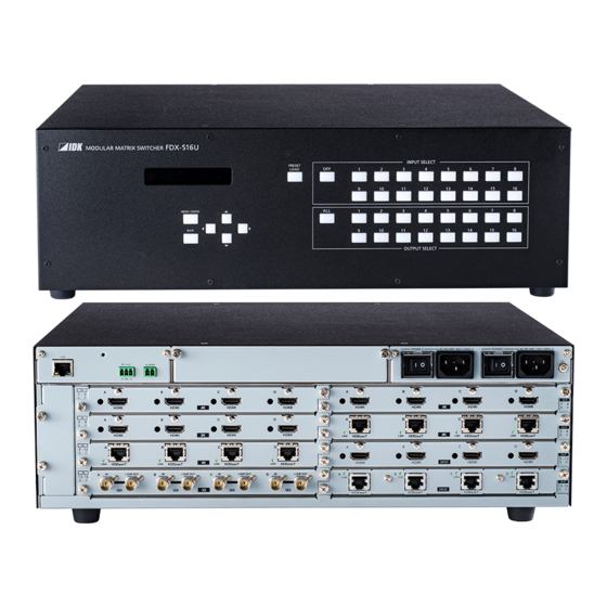
Modular Matrix Switcher
FDX-S Series
FDX- S16U / S32U
FDX- S16 / S32
<User Guide>
Ver.1.0.0
Advertisement
Table of Contents

Related Manuals for IDK FDX-S Series


Summary of Contents for IDK FDX-S Series
- Page 1 Modular Matrix Switcher FDX-S Series FDX- S16U / S32U FDX- S16 / S32 <User Guide> Ver.1.0.0 ⚫ Thank you for choosing our product. ⚫ To ensure the best performance of this product, please read this user guide fully and carefully before using it and keep this manual together with the product for future reference as needed.
- Page 2 ⚫ Oracle and Java are trademarks of Oracle Corporation its subsidiaries, and affiliated companies in the United States and other countries. ⚫ The terms Anti-snow and Connection Reset are registered trademarks of IDK Corporation in Japan. ⚫ All other company and product names mentioned in this manual are either registered trademarks or...
- Page 3 ⚫ Some information contained in this User guide such as exact product appearance, diagrams, menu operations, and so on may differ depending on the product version. ⚫ This User guide is subject to change without notice. You can download the latest version from IDK’s website at: http://www.idkav.com...
- Page 4 FDX-S Series User Guide Safety Instructions Read and understand all safety and operating instructions before using this product. Follow all instructions and heed all warnings/cautions. Enforcement Symbol Description Indicates the presence of a hazard that may result in death or serious...
- Page 5 The product is intended to be installed by skilled technicians. For installation, please contact a system integrator or IDK. Improper installation may lead to the risk of fire, electric shock, injury, or property damage. ● Insert the power plug into an outlet that is unobstructed.
- Page 6 Unplug If you continue to use the product under these conditions, it may increase the risk of electrical shock or fire. For maintenance and repair, contact your IDK representative. ● Unplug immediately if water or other objects are directed inside.
- Page 7 FDX-S Series User Guide Caution ■ For installing and connecting products: ● Do not place the product in a location where it will be subjected to high temperatures. If the product is subjected to direct sunlight or high temperatures while under operation, it may affect the product’s performance and reliability and may increase the risk of fire.
-
Page 8: Table Of Contents
FDX-S Series User Guide Table of Contents 1 About this Guide ............................12 2 Included items ............................... 13 3 About FDX-S Module Matrix Switchers ......................14 4 Features ................................ 15 5 Panels ................................17 5.1 Frame ..............................17 5.1.1 FDX-S16U/S16 ..........................17 5.1.2 FDX-S32U/S32 .......................... - Page 9 FDX-S Series User Guide 10.3 Output position, size, and masking ...................... 51 10.3.1 Output resolution ........................... 51 10.3.2 Aspect ratio for sink device ......................52 10.3.3 Image position ..........................52 10.3.4 Image size ............................. 52 10.3.5 Background color .......................... 53 10.3.6 Test pattern ...........................
- Page 10 FDX-S Series User Guide 10.9.2 Output Lip Sync ..........................70 10.10 Input audio ............................70 10.10.1 Stable input audio wait ........................ 70 10.11 EDID ..............................71 10.11.1 External EDID ..........................71 10.11.2 Resolution............................ 72 10.11.3 Copying EDID ..........................75 10.11.4 HDMI/DVI ............................ 75 10.11.5 Frame rate ...........................
- Page 11 FDX-S Series User Guide 10.17.2 Viewing sink device EDID ......................95 10.17.3 Input signal status ........................95 10.17.4 System status ..........................96 10.17.5 Viewing board status ........................97 10.17.6 Fan status ............................ 98 10.17.7 Power supply voltage status......................98 10.17.8 Device information ........................98 10.18 Factory default list ..........................
-
Page 12: About This Guide
FDX-S Series User Guide 1 About this Guide This guide contains installation, setting, and operating information for the FDX-S series Modular Matrix Switchers (hereafter referred to as “FDX-S”). The FDX-S consists of the modular matrix switcher, redundant power supply unit, and Input/Output boards. -
Page 13: Included Items
FDX-S Series User Guide 2 Included items Ensure that all items illustrated below are included in the package. If any items are missing or damaged, please contact IDK. One (1) frame (Example: FDX-S16U) 3-pin captive screw connector 2-pin captive screw connector... -
Page 14: About Fdx-S Module Matrix Switchers
For long reach mode, video signals up to 1080p (24 bit) can be transmitted to 492 ft. (150 m) at maximum if using with IDK s HDBaseT products supporting 328 ft. (100 m) transmission. Up to 98 ft. (30 m): 1080p@60 Up to 39 ft. -
Page 15: Features
FDX-S Series User Guide 4 Features [1/2] Frame Features Remarks S16U S32U 4K@60 Maximum resolution 4K@30 (4:4:4) HDCP 1.4/2.2 ✓ FDX-SIV4UH, ✓ FDX-SIV4UT, ✓ FDX-SOV4UH, x.v.Color FDX-SOV4UT ✓ ✓ 3G-SDI/HD-SDI/SD-SDI input FDX-SIV4S ✓ ✓ Automatic signal equalization FDX-SOV4HS Output 131 ft. (40 m) ✓... - Page 16 HDBaseT status display : For FDX-S16U/S32U only. : For long reach mode, video signals up to 1080p (24 bit) can be transmitted to 492 ft. (150 m) at maximum if using with IDK's HDBaseT products supporting 328 ft. (100 m) transmission.
-
Page 17: Panels
FDX-S Series User Guide 5 Panels 5.1 Frame 5.1.1 FDX-S16U/S16 Front panel Rear panels ㉑ ㉓ ㉒ ㉔ ㉔ With redundant power supply [Fig. 5.1] Drawings... - Page 18 FDX-S Series User Guide [Table 5.1] Features Feature Description Front panel ① INPUT SELECT button Selects an input. Loads the crosspoint number (in loading crosspoint mode). ② OUTPUT SELECT button Selects an output. ③ PRESET LOAD button Enables preset memory load mode.
-
Page 19: Fdx-S32U/S32
FDX-S Series User Guide 5.1.2 FDX-S32U/S32 Front panel Rear panels ㉒ ㉑ ㉓ ㉓ With redundant power supply [Fig. 5.2] Drawings... - Page 20 FDX-S Series User Guide [Table 5.2] Features [1/2] Feature Description Front panel ① I/O channel selection buttons Buttons Description Numeric buttons Enters number. (0 to 9) Applies the setting. INPUT Moves the cursor to the INPUT side. Does not output video.
-
Page 21: I/O Boards
FDX-S Series User Guide [2/2] Feature Description Rear panels ⑳ Fan unit Replaceable fan unit. ㉑ Power supply unit Primary power supply unit for redundant power supply (Primary) ㉒ Power supply unit Secondary power supply unit for redundant power supply... -
Page 22: Redundant Power Supply Unit
FDX-S Series User Guide 5.3 Redundant power supply unit ■ Redundant power supply units Model Drawing FDX-S16U/S16 FDX-SRP16 FDX-S32U/S32 FDX-SRP32... -
Page 23: System Configuration Example
For long reach mode, video signals up to 1080p (24 bit) can be transmitted to 492 ft. (150 m) at maximum if using with IDK s HDBaseT products supporting 328 ft. (100 m) transmission. [Fig. 6.1] System configuration example (Example: FDX-S16U) -
Page 24: Installation
FDX-S Series User Guide 7 Installation 7.1 Precautions When installing the FDX-S, observe the following precautions; otherwise, the internal temperature increases and it may affect the product lifetime and operation. ・ Do not stack or place one FDX-S directly on top of another FDX-S. -
Page 25: Connection Details
For long reach mode, video signals up to 1080p (24 bit) can be transmitted to 492 ft. (150 m) at maximum if using with IDK s HDBaseT products supporting 328 ft. (100 m) transmission. [Fig. 8.1] Connecting video devices (Example: FDX-S16U) -
Page 26: Securing Hdmi Cable
With long reach mode, video signals up to 1080p (24 bit) can be transmitted to 492 ft. (150 m) at maximum if using with IDK's HDBaseT products supporting 328 ft. (100 m) transmission. Enable the HDBaseT Long reach mode from following menus: For HDBaseT input ・... -
Page 27: Category Cable
FDX-S Series User Guide 8.2.3 Category cable To ensure the best performance with category cables, select a high quality category cable type, ensuring that proper pinning and pairing requirements are observed. ・ Cat5e UTP/STP and Cat6 UTP/STP can be used, but we recommend CAT.5E HDC cable* for optimal performance. -
Page 28: Coaxial Cable
FDX-S Series User Guide The CAT.5E HDC cable is a double-shielded category cable optimized for video signal transmission. The double-shielded structure protects the video signal from external interference. It is certified to 500 MHz bandwidth at distances up to 328 ft. (100 m) and verified to meet requirements specified by HDBaseT Alliance. -
Page 29: Connecting Control Devices
FDX-S Series User Guide 8.3 Connecting control devices Controller Video switching [Fig. 8.3] Application example for control devices (Example: FDX-S16U) -
Page 30: Rs-232C Communication
FDX-S Series User Guide 8.3.1 RS-232C communication ■ Connecting RS-232C cable The FDX-S’s RS-232C connection is supported by a 3-pin captive screw connector. Insert and secure the wires from the RS-232C cable into the supplied 3-pin captive screw connector, and then insert the captive screw connector into the mating connector on the FDX-S. -
Page 31: Alarm
FDX-S Series User Guide 8.3.3 Alarm Connect the provided 2-pin captive screw connector to the “ALARM” connector in order to detect problems in the power supply voltage, cooling fans, internal temperature, and board. 28 AWG to 16 AWG conductor gauge is recommended. -
Page 32: Operation
FDX-S Series User Guide 9 Operation 9.1 Powering on/off Turn on the “POWER” switch of the rear panel to power on the FDX-S. For redundant power supply unit, turn on one of “POWER 1” and “POWER 2” switches and then turn on the other switch within five seconds. -
Page 33: Front Panel Operations
FDX-S Series User Guide 9.2 Front panel operations 9.2.1 Selecting menu To select a menu: 1. Press the “MENU/ENTER” button. 2. Select the desired menu using “arrow” buttons. 3. Press the “MENU/ENTER” button again to proceed to the following hierarchy. -
Page 34: Video Switching
FDX-S Series User Guide 9.2.2 Video switching FDX-S16U/FDX-S16 To output video by selecting an output channel from an input channel or vice versa: 1. Set [ADVANCED MENU] of [SYSTEM SETTINGS] to [ON]. 2. Select “MENU/ENTER” > [FUNCTION SELECT] > [SYSTEM SETTINGS] > [SELECT MODE]. - Page 35 FDX-S Series User Guide ■ [SELECT MODE]: [OUTPUT] → [INPUT] Select an output channel and then input channel. Example 1: Outputting IN1 video to OUT3 The selected output channel button flashes. Example 2: Displaying IN5 video to all output channels The output channel that does not have board cannot be selected.
- Page 36 FDX-S Series User Guide FDX-S32U/FDX-S32 Output video by selecting an output channel from an input channel or vice versa. If no operation is performed for 30 seconds, the FDX-S becomes in energy-saving mode. ■ To select channel (Input channel → Output channel): Select an input channel and then output channel.
- Page 37 FDX-S Series User Guide ■ To select channel (Output channel → Input channel) Select an output channel and then input channel. Example 1: Outputting IN9 video to OUT13 Example 2: Displaying IN5 video to all output channels Example 3: Hiding video of all output channels...
-
Page 38: Recalling Crosspoint
FDX-S Series User Guide 9.2.3 Recalling crosspoint Up to 32 crosspoint configurations can be saved in the preset memory (including crosspoint memory) that can be loaded from menu. Part of FDX-S16U/FDX-S16 preset memory is assigned to I/O channel button and can be loaded by front button operation. -
Page 39: Front Panel Security Lockout
FDX-S Series User Guide FDX-S32U/FDX-S32 Press the “PRESET LOAD” button and preset memory registration number from “I/O channel selection” buttons (0 to 9). [Fig. 9.3] Recalling preset memory 9.2.4 Front panel security lockout The front panel security lockout limits operation of the FDX-S from the front panel to prevent accidental changes. -
Page 40: Initialization
FDX-S Series User Guide PRESET LOAD button I/O channel selection buttons ・ MENU/ENTER button ・ Navigation buttons PRESET LOAD button ・ MENU/ENTER button I/O channel selection buttons ・ Navigation buttons [Fig. 9.4] Buttons/Groups to be locked (Top: FDX-S16U, Bottom: FDX-S32U) To enable/disable the button security lockout, press and hold the “BACK”... -
Page 41: Web Browser Operations
FDX-S Series User Guide 9.3 WEB browser operations The FDX-S can be controlled, monitored, or configures remotely also via WEB browser. 9.3.1 Starting WEB browser To start WEB browser of the FDX-S: Step 1 : Start the WEB browser. Maximizing the window size would be recommended. -
Page 42: Normal/Advanced Menu
FDX-S Series User Guide 9.3.2 Normal/Advanced menu The FDX-S menus consist of normal setting menus and advanced setting menus. To display advanced setting menus: 1. Select [SYSTEM SETTINGS] from [MENU]. 2. Set [ADVANCED MENU] to [ON]. It is set to [OFF] by default. -
Page 43: Registering Bitmap
FDX-S Series User Guide 9.3.4 Registering bitmap To register bitmap file: 1. Select [SYSTEM SETTINGS] from [MENU]. 2. Set [ADVANCED MENU] to [ON]. 3. Select [BITMAP] > [SEND BITMAP] > [Browse…]. 4. Click the [SEND] button to register bitmap file to the bitmap memory. -
Page 44: Automatic Reload
FDX-S Series User Guide 9.3.5 Automatic reload To set automatic reload interval of [CROSSPOINT], [VIEW STATUS], and [HDBT STATUS] windows: 1. Select [SYSTEM SETTINGS] from [MENU]. 2. Select the desired interval in 5-seconds increments (5 to 60 seconds) for [AUTO RELOAD TIME]. -
Page 45: Initialization
FDX-S Series User Guide To restore settings from PC: 1. Select [SYSTEM SETTINGS] from [MENU]. 2. Select a file from [Choose File]. 3. Click the [RESTORE] button of [BACKUP/RESTORE]. Do not perform other WEB operations or power off the FDX-S during the operation. -
Page 46: Configuration And Control
FDX-S Series User Guide 10 Configuration and Control 10.1 Menu The FDX-S menus consist of normal setting menus and advanced setting menus. You can switch setting menu/advanced menu, using the “MENU/ENTER” button ([FUNCTION SELECT] → [SYSTEM SETTINGS] → [ADVANCED MENU]). -
Page 47: Normal Setting Menu
FDX-S Series User Guide 10.1.1 Normal setting menu FDX-S Series │ │ ├─CROSS POINT P.51 ├─LAN SETTINGS P.80 │ │(CROSS POINT) │ │(LAN) │ └─VIEW SELECTED CHANNELS │ ├─IP ADDRESS │ (Displaying crosspoint) │ │ (IP address) │ │ ├─SUBNET MASK ├─OUTPUT IMAGE P.51... -
Page 48: Advanced Setting Menu
FDX-S Series User Guide 10.1.2 Advanced setting menu FDX-S Series │ │ │ │ ├─EDID ERR. OUTPUT MODE ├─CROSS POINT P.51 │ │ (Sink device EDID check) │ │(CROSS POINT) │ ├─HOTPLUG MASK │ └─VIEW SELECTED CHANNELS │ │ (Hot plug ignoring duration) │... - Page 49 FDX-S Series User Guide │ │ │ │ │ ├─OUTPUT SETTING INIT. ├─RS-232C SETTINGS P.80 │ │ (Output video correction initialization) │ │(RS-232C) │ ├─INPUT SHARPNESS │ └─PARAMETERS │ │ (Input sharpness) │ (RS-232C communication) │ ├─INPUT BRIGHTNESS │ │ │ (Input brightness) ├─LAN SETTINGS P.80...
- Page 50 FDX-S Series User Guide │ ├─SYSTEM SETTINGS P.89 │ │(Configuring FDX-S) │ ├─BUTTON LOCK TARGET │ │ (Grouping front panel security lockout) │ ├─BEEP SOUND │ │ (Beep) │ ├─ALARM │ │ (Alarm) │ ├─ADVANCED MENU │ │ (Displaying advanced menu) │...
-
Page 51: Displaying Crosspoint
FDX-S Series User Guide 10.2 Displaying crosspoint Menu Top→CROSS POINT→VIEW SELECTED CHANNELS You can view crosspoint of input and output channels. OFF: No channel is assigned. [Fig. 10.1] Displaying selected I/O channels 10.3 Output position, size, and masking 10.3.1 Output resolution... -
Page 52: Aspect Ratio For Sink Device
FDX-S Series User Guide 10.3.2 Aspect ratio for sink device Scan conversion output only Menu Top→OUTPUT IMAGE→ASPECT RATIO Setting for OUT01 to OUTn ・RESOLUTION* [Default] ・16:10 ・16:9 Setting value ・5:3 ・5:4 ・4:3 * If you select “RESOLUTION”, the aspect ratio of the output resolution will be applied. If aspect ratios of the target sink device and the output resolution are different from each other, you can select one of the following aspect ratios for the sink device: “4:3”, “5:4”, “5:3”, “16:9”, and “16:10”. -
Page 53: Background Color
FDX-S Series User Guide 10.3.5 Background color Scan conversion output only Menu Top→OUTPUT IMAGE→BACKGROUND COLOR Setting for ALL, OUT01 to OUTn Setting value R/G/B: 0 to 255 [Default] R/G/B: 0 (Black) You can set the background color of output video signal. -
Page 54: Videowall Configuration
FDX-S Series User Guide 10.3.7 Videowall configuration Scan conversion output only Menu Top→OUTPUT IMAGE→VIDEO WALL TYPE Setting for OUT01 to OUTn Setting value H: -- (Not control), 01 to 20 (The number of horizontal screens : 1 to 20) [Default] 01... -
Page 55: Frame Delay
FDX-S Series User Guide 10.3.9 Frame delay Scan conversion output only Menu Top→OUTPUT IMAGE→VIDEO FRAME DELAY Setting for OUT01 to OUTn Setting value OFF : No frame delay [Default] : 1 frame delay : -1 frame delay You can set the frame delay for videowall. -
Page 56: Video Synchronization
FDX-S Series User Guide 10.3.11 Video synchronization Scan conversion output only Menu Top→OUTPUT IMAGE→VIDEO SYNC PROCESSING Setting for ALL, OUT01 to OUTn Setting value OFF [Default], ON You can enable/disable video synchronization. Set the same resolution to each video output signal. If not, signals cannot be synchronized. -
Page 57: Output
FDX-S Series User Guide 10.4 Output Settings for video output and output connectors 10.4.1 Disabling synchronous signal output when no video signal is input Menu Top→OUTPUT SETTINGS→SYNC. SIGNAL OUTPUT Scan conversion output only Setting for ALL, OUT01 to OUTn Setting value OFF [Default], 5 sec. -
Page 58: Output Equalizer
Middle ✓ HIGH High * IDK’s cable (24 AWG) was used Each HDMI output connector includes an equalizer that compensates for signal attenuation when long HDMI cables are connected. Note: If a cable equalizer, active cable, or the like is connected, the FDX-S may not equalize output correctly. In such a case, set this menu to “OFF”. -
Page 59: Hdbaset Output Long Reach Mode
Up to 492 ft. (150 m) You can enable/disable long reach mode for HDBaseT output. With long reach mode, up to 1080p (24 bit)/dot clock 148 MHz is supported when using with IDK’s HDBaseT product. Select a supported output format. -
Page 60: Sink Device Edid Check
FDX-S Series User Guide 10.4.9 Sink device EDID check Menu Top→OUTPUT SETTINGS→EDID ERR. OUTPUT MODE Setting for OUT01 to OUTn Setting value [Table 10.5] Sink device EDID check Setting value Description OFF [Default] In case of error, treated as DVI... -
Page 61: Presence Of Output Signal For When No Signal Is Input (No Scan Conversion)
FDX-S Series User Guide 10.4.11 Presence of output signal for when no signal is input (No scan conversion) Menu Top→OUTPUT SETTINGS→DDC POWER OUT Setting for ALL, OUT01 to OUTn Setting value ON [Default], OFF If setting to “ON”, the +5V signal is output regardless of the presence of input signal, some sink devices are not in standby mode. -
Page 62: Input
FDX-S Series User Guide 10.6 Input Settings for video input and input connectors 10.6.1 No-signal input monitoring Boards other than SDI Menu Top→INPUT SETTINGS→NO INPUT MONITORING Setting for ALL, IN01 to INn Setting value OFF, 3Sec to 15Sec (by 1Sec) [Default] 10Sec If you change the EDID settings of the FDX-S or power the FDX-S off/on, the source device may not output a video signal. -
Page 63: Hdcp Input
FDX-S Series User Guide 10.6.2 HDCP input Boards other than SDI Menu Top→INPUT SETTINGS→HDCP INPUT MODE Setting for IN01 to INn Setting value HDCP 2.2 : Enabling HDCP 2.2 and HDCP 1.4 [Default] HDCP 1.4 : Enabling HDCP 1.4 [Default] DISABLE : Disabling HDCP Some source devices negotiate with the connected device to determine if HDCP encryption is supported. -
Page 64: Hdbaset Input Long Reach Mode
Up to 492 ft. (150 m) With long reach mode, up to 1080p (24 bit)/dot clock 148 MHz is supported when using with IDK’s HDBaseT product. Set the FDX-S’s EDID to 1080p or less or set the connected device’s output to a supported signal format. -
Page 65: Input Timing
FDX-S Series User Guide 10.7 Input timing You can set the timing parameters for analog signal inputs. Vertical direction Vertical sync signal (V SYNC) Horizontal active area Video to be displayed to sink device Horizontal direction The total number of horizontal pixels... -
Page 66: Horizontal Active Area
FDX-S Series User Guide 10.7.2 Horizontal active area Scan conversion output only Menu Top→INPUT TIMING→H ACTIVE Setting for IN01 to INn for each input signal Setting value -100DOT to +100DOT [Default] 0DOT You can set the horizontal active area of input video. -
Page 67: Picture Controls
FDX-S Series User Guide 10.8 Picture controls Setting items for input channels are for correcting color bias. Image quality to be output can be set for each input channel and output channel as follows: Output Input Brightness Brightness Saturation Input video... -
Page 68: Output Video Correction Initialization
FDX-S Series User Guide 10.8.4 Output video correction initialization Scan conversion output only Menu Top→PICTURE ADJUSTMENT→OUTPUT SETTING INIT. Setting for ALL, OUT01 to OUTn Setting value OFF [Default], INITIALIZE: Initializes the following settings of output video: 10.8.1 Output brightness 10.8.2 Output contrast 10.8.3 Output gamma... -
Page 69: Input Hue
FDX-S Series User Guide 10.8.8 Input hue Scan conversion output only Menu Top→PICTURE ADJUSTMENT→INPUT HUE Setting for IN01 to INn for each input signal Setting value 0° to 359° [Default] 0° You can set the color HUE for each input signal. -
Page 70: Output Audio
FDX-S Series User Guide 10.9 Output audio 10.9.1 Mute Menu Top→OUTPUT AUDIO SETTINGS→MUTE Setting for ALL, OUT01 to OUTn Setting value OFF [Default], ON You can mute/unmute the audio. 10.9.2 Output Lip Sync Scan conversion output only Menu Top→OUTPUT AUDIO SETTINGS→LIP SYNC... -
Page 71: Edid
FDX-S Series User Guide 10.11 EDID Boards other than SDI EDID can be set using the following data: Built-in EDID Changing input resolution Frame rate Changing Deep Color input Changing audio format Changing speaker configuration External EDID Blu-ray player Copy DATA [Fig. -
Page 72: Resolution
FDX-S Series User Guide 10.11.2 Resolution Boards other than SDI Menu Top→EDID SETTINGS→RESOLUTION Setting for IN01 to INn Setting value [Table 10.7] Maximum resolution of EDID You can set the supported video resolution. This setting will also be applied for controlling output resolution when AV devices (such as Blu-ray players) are connected via HDMI. - Page 73 FDX-S Series User Guide [2/2] Setting Maximum resolution Pixels Standard Remarks value WXGA 1280×768 VESA WXGA 1280×800 MAC supported Quad-VGA 1280×960 SXGA 1280×1024 WXGA 1360×768 WXGA 1366×768 SXGA+ 1400×1050 1440×900 WXGA+ WXGA++ 1600×900 UXGA 1600×1200 VESA WSXGA+ 1680×1050 VESA1080 1920×1080...
- Page 74 FDX-S Series User Guide [Table 10.8] Supported resolution Supported resolution Input resolution setting - - - - - - - - - - - - - - - - - - - - - - - - - - -...
-
Page 75: Copying Edid
FDX-S Series User Guide 10.11.3 Copying EDID Boards other than SDI Menu Top→EDID SETTINGS→SINK DEVICE EDID COPY Setting for Each copied EDID stored area (1[xxx] to 4[xxx]) Setting value OUT01[xxx] to OUTn[xxx] : EDID data if sink device that is connected to output connector “xxx”:... -
Page 76: Deep Color
FDX-S Series User Guide 10.11.6 Deep Color Boards other than SDI Menu Top→EDID SETTINGS→DEEP COLOR Setting for ALL, IN01 to INn Setting value 24Bit [Default], 30Bit, 36Bit You can set the color depth to be output from the source device. -
Page 77: Aac Audio
FDX-S Series User Guide 10.11.8 AAC audio Boards other than SDI Menu Top→EDID SETTINGS→AAC Setting for ALL, IN01 to INn Setting value ・OFF [Default] ・96kHz ・88.2kHz ・48kHz ・44.1kHz ・32kHz You can set the maximum AAC audio sampling frequency that is output from the source device. -
Page 78: Dolby Truehd Audio
FDX-S Series User Guide 10.11.11 Dolby TrueHD audio Boards other than SDI Menu Top→EDID SETTINGS→Dolby TrueHD Setting for ALL, IN01 to INn Setting value ・OFF [Default] ・192kHz ・176.4kHz ・96kHz ・88.2kHz ・48kHz ・44.1kHz You can set the maximum Dolby TrueHD audio sampling frequency that is output from the source device. -
Page 79: Speaker Configuration
FDX-S Series User Guide 10.11.14 Speaker configuration Boards other than SDI Menu Top→EDID SETTINGS→SPEAKER CONFIGURATION Setting for ALL, IN01 to INn Setting value ・5.1CH: 5.1 channel surround sound ・ 2CH: LR [Default] ・2.1CH: 2.1 channel surround sound ・7.1CH: 7.1 channel surround sound You can set the speaker configuration for multi-channel audio. -
Page 80: Rs-232C
FDX-S Series User Guide 10.12 RS-232C 10.12.1 RS-232C communication Menu Top→RS-232C SETTINGS→PARAMETERS Setting value [Table 10.10] RS-232C communication Parameter Setting value Default Baud rate [bps] 4800, 9600, 14400, 19200, 38400 9600 Data bit length [bit] 8, 7 Parity check NONE, EVEN, ODD... -
Page 81: Mac Address
FDX-S Series User Guide 10.13.3 MAC address Menu Top→LAN SETTINGS→MAC ADDRESS You can display the FDX-S’s MAC address. 10.13.4 TCP port number Menu Top→LAN SETTINGS→PORT NUMBER Setting value [Table 10.11] TCP port number 1: Control from communication commands 1100 [Default], 6000 to 6999... -
Page 82: Preset Memory
FDX-S Series User Guide 10.14 Preset memory Up to 32 crosspoint memories of video I/O channel can be saved. Up to 32 preset memories of video I/O settings can be saved. 10.14.1 Recalling crosspoint Menu Top→USER PRESET→RECALL CROSSPOINT Setting for 01 to 32 [Fig. -
Page 83: Editing Crosspoint
FDX-S Series User Guide ■ For writing “C” : The setting (“---”) will be kept in the crosspoint memory. “D” : The current input channel settings will be overwritten. OUT = Input channel 1 OUT = Not control OUT =... -
Page 84: Recalling Preset Memory
FDX-S Series User Guide 10.14.4 Recalling preset memory Menu Top→USER PRESET→RECALL PRESET SETTINGS Setting for 01 to 32 [RECALL PRESET SETTINGS] [Fig. 10.18] Front display (Sample) You can recall settings that are saved in the preset memories. Press the “MENU/ENTER” button to apply the setting. -
Page 85: Start-Up Setting
FDX-S Series User Guide 10.14.6 Start-up setting Menu Top→USER PRESET→START-UP Setting value [Table 10.14] Start-up setting Setting value Description LAST CHANNEL [Default] Starts with the settings last time the FDX-S powered off. CHANNEL OFF Turns channel OFF. PRESET MEMORY 1 to Starts with the settings saved in the preset memory. -
Page 86: Bitmap
FDX-S Series User Guide 10.15 Bitmap Scan conversion output only You can set the bitmap image to be displayed on the sink device. IDK’s logo is output by default. A bitmap can be enlarged but cannot be reduced. ■ Conditions of bitmap file... -
Page 87: Bitmap Image Output
FDX-S Series User Guide 10.15.1 Bitmap image output Scan conversion output only Menu Top→BITMAP→BITMAP OUTPUT Setting for ALL, OUT1 to OUTn Setting value OFF [Default], ON [Fig. 10.19] Default bitmap image You can enable/disable the bitmap image output. 10.15.2 Background color... -
Page 88: Image Position
FDX-S Series User Guide 10.15.4 Image position Scan conversion output only Menu Top→BITMAP→IMAGE POSITION Setting for ALL, OUT1 to OUTn Setting value CENTER [Default], BOTTOM-RIGHT, TOP-RIGHT, BOTTOM-LEFT, TOP-LEFT You can set the image position of the bitmap. [Fig. 10.21] Position 10.15.5 Start-up bitmap output... -
Page 89: Configuring Fdx-S
FDX-S Series User Guide 10.16 Configuring FDX-S 10.16.1 Grouping front panel security lockout Menu Top→SYSTEM SETTINGS→BUTTON LOCK TARGET Setting for CHANNEL, MENU, PRESET Setting value [Table 10.16] Target buttons of security lockout Setting for Target button Setting value “INPUT SELECT” button,... -
Page 90: Alarm
FDX-S Series User Guide 10.16.3 Alarm Menu Top→SYSTEM SETTINGS→ALARM Setting value ON : Enabling [Default] OFF : Disabling Rated voltage : 24 V Rated current : 300 mA [Fig. 10.22] Alarm output You can enable/disable the alarm function for detecting problems in power supply voltage, cooling fan, internal temperature, or board. -
Page 91: Displaying Advanced Menu
FDX-S Series User Guide 10.16.4 Displaying advanced menu Menu Top→SYSTEM SETTINGS→ADVANCED MENU Setting value OFF : Displays normal setting menu [Default] ON : Displays advanced setting menu You can switch menu display mode: Normal setting menu or Advanced setting menu. -
Page 92: Top Page
FDX-S Series User Guide 10.16.6 Top page Menu Top→SYSTEM SETTINGS→TOP PAGE Setting value OFF [Default], ON You can view input signal, sink device EDID, and sink device status using ▲, ▼, , and buttons. 【See: 10.17.3 Input signal status】 【See: 10.17.1 Sink device status】... - Page 93 FDX-S Series User Guide [Table 10.19] Top page of front display [1/2] Number (① to ㉖) Description ① Input channel number 01 to n ② Input resolution No Signal: No signal is input. When no input board is installed, “-------------” is displayed.
-
Page 94: Channel Selection Mode
FDX-S Series User Guide [2/2] Number (① to ㉖) Description ⑲ HDR ON: Supported, -- : Not supported ⑳ SCDC ON: Supported, -- : Not supported, UNCONNECTED : No sink device is connected., When no output board is installed, “-------------” is displayed. -
Page 95: Status Indication
FDX-S Series User Guide 10.17 Status indication 10.17.1 Sink device status Menu Top→VIEW STATUS→SINK DEVICE STATUS You can view the status of sink device connected to video output connectors. 【See: 10.16.6 Top page】 10.17.2 Viewing sink device EDID Menu Top→VIEW STATUS→SINK DEVICE EDID You can display the EDID information of the sink device that is connected to each video output connector. -
Page 96: System Status
FDX-S Series User Guide 10.17.4 System status Menu Top→VIEW STATUS→SYSTEM STATUS [SYSTEM STATUS] [SYSTEM STATUS] GOOD MAIN FAN TEMP IN OUT No abnormality is detected Abnormality in fan is detected [Fig. 10.25] System status [Table 10.20] System error Displayed value Description Appears in case an abnormality in the power supply voltage is detected. -
Page 97: Viewing Board Status
FDX-S Series User Guide 10.17.5 Viewing board status Menu Top→VIEW STATUS→BOARD STATUS You can view internal temperature and board status. “OK” means normal, and “NG” means abnormal. [Table 10.21] Board status displayed in front display Input/ Description Value to be displayed... -
Page 98: Fan Status
FDX-S Series User Guide 10.17.6 Fan status Menu Top→VIEW STATUS→FAN STATUS You can view fan rotation speed and fan status. “OK” means normal, and “NG” means abnormal. Note: In case an abnormality is displayed, the FDX-S may have problems. Please contact us. -
Page 99: Factory Default List
FDX-S Series User Guide 10.18 Factory default list [1/3] Menu Factory default - CROSS POINT VIEW SELECTED CHANNELS OUTPUT IMAGE RESOLUTION AUTO ASPECT RATIO RESOLUTION IMAGE POSITION H/V: 0 IMAGE SIZE H/V: 100% BACKGROUND COLOR R/G/B: 0 (Black) TEST PATTERN... - Page 100 FDX-S Series User Guide [2/3] Menu Factory default OUTPUT AUDIO MUTE SETTINGS LIP SYNC 0 ms INPUT AUDIO SETTINGS STABLE WAIT EDID SETTINGS CH. FOR EXTERNAL MODE OUT 1 RESOLUTION FDX-SIV4UH: 42 : 2160p (50/59.94/60, 4:4:4) FDX-SIV4UT: 41 : 2160p (50/59.94/60, 4:2:0) FDX-SIV4H: 5 : 1080p (59.94/60)
- Page 101 FDX-S Series User Guide [3/3] Menu Factory default BITMAP BITMAP OUTPUT BACKGROUND COLOR R/G/B: 0 ASPECT RATIO AUTO IMAGE POSITION CENTER START-UP BITMAP SYSTEM SETTINGS BUTTON LOCK TARGET MENU/PRESET/CHANNEL: LOCK BEEP SOUND ALARM ADVANCED MENU POWER SAVE MODE INPUT → OUTPUT...
-
Page 102: Product Specification
FDX-S Series User Guide 11 Product specification 11.1 FDX-S16U Item Description Input board Up to 4 boards (Up to 16 inputs) Output board Up to 4 boards (Up to 16 outputs) Video Up to 4K@60 (4:4:4) Transmission Audio Multi-channel LPCM up to 8 channels... -
Page 103: Fdx-S16
FDX-S Series User Guide 11.2 FDX-S16 Item Description Input board Up to 4 boards (Up to 16 inputs) Output board Up to 4 boards (Up to 16 outputs) Video Up to 4K@30 Transmission Audio Multi-channel LPCM up to 8 channels... -
Page 104: Fdx-S32U
FDX-S Series User Guide 11.3 FDX-S32U Item Description Input board Up to 8 boards (Up to 32 inputs) Output board Up to 8 boards (Up to 32 outputs) Video Up to 4K@60 (4:4:4) Transmission Audio Multi-channel LPCM up to 8 channels... -
Page 105: Fdx-S32
FDX-S Series User Guide 11.4 FDX-S32 Item Description Input board Up to 8 boards (Up to 32 inputs) Output board Up to 8 boards (Up to 32 outputs) Video Up to 4K@30 Transmission Audio Multi-channel LPCM up to 8 channels... -
Page 106: Fdx-Siv4H
The maximum transmission distance is the shorter distance of connected HDBaseT product or sink device’s maximum transmission distance. Up to 492 ft. (150 m): 1080p (24 bit) in Long reach mode. For Long reach mode, use IDK’s HDBaseT Products that supports 328 ft. (100 m) or longer. -
Page 107: Fdx-Siv4S
EDID setting. The maximum cable distance varies depending on the connected devices and was measured under following conditions: ・1080p@60 : When IDK’s 24 AWG cable was used and signals of 1080p@60 24 bit/pixel (8 bit/component) was input. ・4K@60 : When IDK’s 18 Gbps supported cable was used and signals of 4K@60 24 bit/pixel (8 bit/component) was input. -
Page 108: Fdx-Siv4Ut
The maximum transmission distance is the shorter distance of connected HDBaseT product or sink device’s maximum transmission distance. Up to 492 ft. (150 m): 1080p (24 bit) in Long reach mode. For Long reach mode, use IDK’s HDBaseT Products that supports 328 ft. (100 m) or longer. -
Page 109: Fdx-Sov4T
The maximum transmission distance is the shorter distance of connected HDBaseT product or sink device’s maximum transmission distance. Up to 492 ft. (150 m): 1080p (24 bit) in Long reach mode. For Long reach mode, use IDK’s HDBaseT Products that supports 328 ft. (100 m) or longer. -
Page 110: Fdx-Sov4Ts
The maximum transmission distance is the shorter distance of connected HDBaseT product or sink device’s maximum transmission distance. Up to 492 ft. (150 m): 1080p (24 bit) in Long reach mode. For Long reach mode, use IDK’s HDBaseT Products that supports 328 ft. (100 m) or longer. -
Page 111: Fdx-Sov4Ut
The maximum transmission distance is the shorter distance of connected HDBaseT product or sink device’s maximum transmission distance. Up to 492 ft. (150 m): 1080p (24 bit) in Long reach mode. For Long reach mode, use IDK’s HDBaseT Products that supports 328 ft. (100 m) or longer. -
Page 112: Troubleshooting
FDX-S Series User Guide 12 Troubleshooting This chapter provides recommendations in case difficulties are encountered during FDX-S setup and operation. In case the FDX-S does not work correctly, please check the following items first. ・ Are the FDX-S and all devices connected to power and powered on? ・... - Page 113 If the error is solved by replacing the cable, the signal may have been degraded due to excessive attenuation or crosstalk. IDK offers high-quality cables, cable boosters and extenders. Please contact us as needed.
- Page 114 FDX-S Series User Guide Problem Cause/Check item/Solution Page ● Video output (Cont’d) Video is intermittent, Is a cable appropriated for the transmission when 4K@30/60 or presents noise. HDBaseT I/O board is installed? If the transmission distance is 164 ft. (50 m) or longer, we...
- Page 115 FDX-S Series User Guide Problem Cause/Check item/Solution Page ● Audio output Audio is not being Ensure that audio output is turned on. - output. If there are multiple output connectors in the source device, check the audio output setting of the source device.
- Page 116 FDX-S Series User Guide If additional assistance is required, please perform the following tests and then contact us. Checking items Result The problem occurs at all connectors? Yes or No Connect the devices using genuine cables without connecting the FDX-S.
- Page 117 7-9-1 Chuo, Yamato-shi, Kanagawa-pref. 242-0021 JAPAN TEL: +81-46-259-6920 FAX: +81-46-259-6930 Email: info@arvanics.com URL: http://www.arvanics.com Information in this document is subject to change without notice. ©2020 IDK Corporation, all rights reserved. All trademarks mentioned are the property of their respective owners.
Need help?
Do you have a question about the FDX-S Series and is the answer not in the manual?
Questions and answers