Sign In
Upload
Manuals
Brands
YOKOGAWA Manuals
Test Equipment
DL7480
YOKOGAWA DL7480 Manuals
Manuals and User Guides for YOKOGAWA DL7480. We have
4
YOKOGAWA DL7480 manuals available for free PDF download: User Manual, Operation Manual
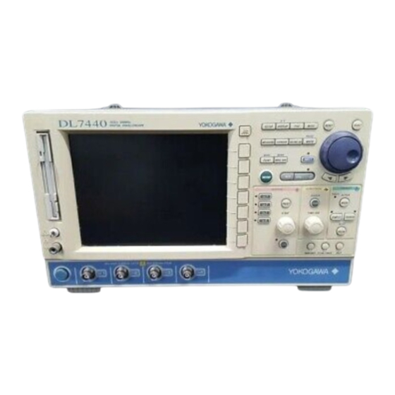
YOKOGAWA DL7480 User Manual (501 pages)
Digital Oscilloscope
Brand:
YOKOGAWA
| Category:
Test Equipment
| Size: 7.97 MB
Table of Contents
Product Registration
2
Checking the Contents of the Package
5
Standard Accessories
6
Safety Precautions
8
Conventions Used in this Manual
10
Flow of Operation
11
Table of Contents
12
Chapter 1 Names and Functions of Parts
17
Front Panel, Rear Panel, and Top Panel
17
Panel Keys and Knobs
19
Display
22
Chapter 2 Explanation of Functions
25
System Configuration and Block Diagram
25
System Configuration,Block Diagram
25
Vertical and Horizontal Axes
26
Trigger
32
Waveform Acquisition and Display Conditions
39
Waveform Computation
45
Analyzing and Searching Waveforms
49
Automated Measurement of Waveform Parameters,Go/No-GO Determination
54
Communication
56
Saving and Loading Data from a Network Drive (FTP Client)
56
Other Useful Functions
58
Saving and Loading Data from the Storage Medium
59
Operating the DL7400 Using a Free Software Program
59
Chapter 3 Making Preparations for Measurements
60
Handling Precautions
60
Installing the Instrument
62
Connecting the Power Supply and Turning ON/OFF the Power Switch
64
Connecting the Probe
66
Compensating the Probe (Phase Correction)
69
Connecting Logic Probes (Optional)
70
Setting the Date and Time
72
Chapter 4 Common Operations
74
Operations and Functions of Keys and the Jog Shuttle
74
Entering Values and Strings
76
Operating the DL7400 Using a USB Keyboard or a USB Mouse
79
Initializing Settings
87
Performing Auto Setup
89
Performing Calibration
92
Correcting the Delay Time of the Input Signals
94
Using the Help Function
96
Chapter 5 Vertical and Horizontal Axes
97
Turning Channels ON/OFF
97
Setting V/DIV
98
Setting the Vertical Position of the Waveform
100
Setting the Input Coupling
102
Selecting the Probe Attenuation/Current-To-Voltage Conversion Ratio
104
Setting the Offset Voltage
105
Using the Preset Function
107
Setting Bandwidth Limits
110
Using the Linear Scaling Function
111
Turning ON/OFF the Logic Input and Setting the Threshold Level
113
Selecting the Time Base
116
Setting T/DIV
118
Chapter 6 Triggers
119
Selecting the Trigger Mode
119
Setting the Trigger Position
121
Setting the Trigger Delay
123
Setting the Hold off Time
124
Setting the Edge Trigger (SIMPLE)
127
Setting the External Trigger (SIMPLE)
130
Activating Triggers on the Commercial Power Supply (SIMPLE)
132
Setting the A->B(N) Trigger (ENHANCED)
133
Setting the a Delay B Trigger (ENHANCED)
136
Setting the Pattern Trigger (ENHANCED)
139
Setting the Width (Pulse<Time, Pulse>Time, T1<Pulse<T2, and Time Out) Trigger (ENHANCED)
143
Setting the or Trigger (ENHANCED)
148
Setting the Window Trigger (ENHANCED)
151
Setting the TV Trigger (ENHANCED)
154
Setting the Logic Trigger (ENHANCED, Optional)
159
Setting the Action-On-Trigger
162
Setting the Trigger Gate
164
Chapter 7 Waveform Acquisition
166
Starting/Stopping Waveform Acquisition
166
Setting the Record Length
167
Using Interleave Mode
168
Turning ON/OFF Repetitive Sampling Mode
169
Setting the Acquisition Mode
171
Performing Sequential Store (SINGLE(N) Mode)
175
Chapter 8 Waveform Display and Information Display
177
Setting the Display Format
177
Performing Display Interpolation
180
Accumulating Waveforms
182
Zooming the Waveform
184
Displaying X-Y Waveforms
188
Taking Snapshots and Clearing Traces
191
Changing the Graticule
192
Turning ON/OFF the Scale Display
193
Setting Waveform Labels and Turning ON/OFF the Display
194
Turning ON/OFF the Translucent Display
196
Chapter 9 Waveform Computation
197
Entering Normal Computation Mode, Displaying Computed Waveforms, and Assigning Labels to Computed Waveforms
197
Adding, Subtracting, and Multiplying Waveforms
199
Performing Binary Computation
202
Inverting Waveforms
204
Differentiating and Integrating Waveforms
206
Performing Power Spectrum Computation (FFT)
208
Smoothing Waveforms
211
Shifting the Phase
213
Performing User-Defined Computation (Optional)
215
Chapter 10 Analyzing and Searching Waveforms
226
Displaying History Waveforms
226
Searching the History Waveforms Using Zones (History Search)
230
Searching History Waveforms Using Waveform Parameters (History Search)
235
Searching Waveforms Using the Search and Zoom Function
240
Making Cursor Measurements
258
Automated Measurement of Waveform Parameters
271
Performing Statistical Processing of the Measured Values of Waveform Parameters
279
Performing Automated Measurements of Waveform Parameters on Dual Areas
286
Performing GO/NO-GO Determination Using Zones
291
Performing GO/NO-GO Determination Using Measured Waveform Parameters
297
Analyzing and Searching SPI Signals
301
Chapter 11 Printing Screen Images
314
Installing the Roll Paper into the Built-In Printer (Optional)
314
Printing Using the Built-In Printer (Optional)
316
Printing Using a USB Printer
319
Printing Using a Network Printer (Optional)
324
Chapter 12 Saving and Loading Data
327
Storing and Recalling Setup Data
327
Floppy Disk, Zip Disk, and PC Cards
329
Connecting MO Disk Drives or Hard Disks to the SCSI
333
Changing the SCSI ID Number
334
Connecting USB Storage to the USB PERIPHERAL Interface
335
Formatting the Storage Medium
336
Saving/Loading the Setup Data
341
Saving/Loading the Waveform Data
346
Saving/Loading the Snapshot Waveforms
354
Saving the Results of the Automated Measurement of Waveform Parameters
357
Saving the Detailed Analysis List of SPI Signals
359
Saving Screen Image Data
361
Displaying Thumbnails of the Saved Screen Image Data
365
Changing the File Attributes and Deleting Files
369
Copying Files
373
Changing the Directory or File Name of the Storage Medium and Creating Directories
376
Chapter 13 Ethernet Communications (Optional)
380
Connecting the DL7400 to the Network
380
Setting up TCP/IP
382
Saving and Loading Waveform/Setup/Image Data on a Network Drive (FTP Client Function)
387
Entering Settings for Printing Screen Images on the Network Printer (LPR Client Function)
390
Sending Periodic or Action Mail (SMTP Client Function)
391
Accessing the DL7400 from a PC or Workstation (FTP Server Function)
395
Using the Web Server Function
397
System Requirements
398
Setting the Time Difference from GMT (Greenwich Mean Time)
420
Checking the Presence of the Ethernet Interface (Optional) and the MAC Address
422
Setting the FTP Passive Mode and LPR/SMTP Timeout
423
Using the Storage Medium as a Windows Network Drive (Firmware Version 1.30 or Later)
425
Chapter 14 Rear Panel Auxiliary I/O Section
427
External Trigger Input, External Clock Input, and Trigger Gate Input
427
Trigger Output
429
Video Signal Output (VIDEO out (VGA))
431
Chapter 15 Other Operations
432
Changing the Message Language and Turning ON/OFF the Click Sound
432
Changing the USB Keyboard Language and Checking the Connected USB Keyboard
433
Measuring the Offset Voltage and Applying the Offset Voltage to
434
The Computed Results
434
Setting the Screen Color and Intensity
435
Turning off the Backlight and Setting the Brightness of the Backlight
437
Chapter 16 Troubleshooting, Maintenance, and Inspection
439
Troubleshooting
439
Messages and Corrective Actions
440
Performing a Self-Test
446
Checking the System Conditions (Overview)
449
Recommended Replacement Parts
450
Chapter 17 Specifications
451
Input Section
451
Logic Input Section (Optional)
452
Trigger Section
452
Time Axis
454
Display
454
Function
454
Built-In Printer (Optional)
457
Storage
457
USB Peripheral Interface
458
Auxiliary I/O Section
458
Computer Interface
459
General Specifications
460
External Dimensions
462
Appendix
463
Relationship between the Time Axis Setting, Sample Rate and Record Length
464
Appendix 2 How to Calculate the Area of a Waveform
474
ASCII Header File Format
477
Appendix 3 ASCII Header File Format
478
Appendix 4 User-Defined Computation
480
Appendix 5 List of Default Settings
488
Appendix 6 Key Assignments of the USB Keyboard
490
Advertisement
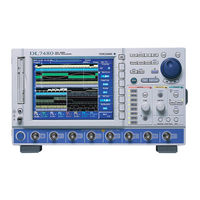
YOKOGAWA DL7480 User Manual (176 pages)
Digital Oscilloscope Serial Bus Signal Analysis Function (Includes the I2 C Bus Signal/CAN Bus Signal/ SPI Bus Signal Analysis Function)
Brand:
YOKOGAWA
| Category:
Test Equipment
| Size: 1.48 MB
Table of Contents
Conventions Used in this Manual
3
Table of Contents
4
Chapter 1 I 2 C Bus Signal Analysis Function
6
Overview of the I
6
Bus Signal Analysis Function
6
Flow of Operation
7
Connecting the Probe
8
Setting the I 2 C Bus Signal Acquisition Conditions
9
Setting the Trigger Conditions of the I C Bus Signal
9
Setting the Start Condition or Stop Condition
11
Setting the Combination Trigger
12
Setting the Trigger Level, Trigger Coupling, Etc
14
Setting the Trigger Mode
14
Setting the Record Length
14
Starting/Stopping the I 2 C Bus Signal Acquisition
14
Examples of Setting the Trigger Conditions of the I 2 C Bus Signal
20
Analyzing/Searching Data
30
Saving the Data of the Detailed Analysis List
40
Error Messages
42
Communication Commands
43
Chapter 2 CAN Bus Signal Analysis Function
56
Overview of the CAN Bus Analysis Function
56
Flow of Operation
57
Connecting the Probe
58
Setting CAN Bus Signal Acquisition Conditions
60
Setting the Trigger Conditions of the CAN Bus Signal
60
Setting the Combination Trigger
64
Setting the Trigger Level, Trigger Coupling, Etc
66
Setting the Trigger Mode
66
Setting the Record Length
73
Starting/Stopping the CAN Bus Signal Acquisition
73
Analyzing/Searching Data
74
Using Cursors
90
Saving the Data of the Detailed Analysis List
93
Error Messages
95
Communication Commands
96
Chapter 3 SPI Bus Signal Analysis Function
113
Overview of the SPI Bus Signal Analysis Function
113
Flow of Operation
115
Connecting the Probe
116
Setting SPI Bus Signal Acquisition Conditions
117
Setting the Trigger Conditions of the SPI Bus Signal
117
Setting the Combination Trigger
119
Setting the Trigger Level, Trigger Coupling, Etc
122
Setting the Trigger Mode
122
Setting the Record Length
122
Starting/Stopping the SPI Bus Signal Acquisition
122
Examples of SPI Bus Signal Trigger Conditions
128
Analyzing/Searching Data
135
Saving the Data of the Detailed Analysis List
149
Error Messages
151
Communication Commands
152
Chapter 4 Specification
169
I 2 C Bus Signal Analysis Function
169
CAN Bus Signal Analysis Function
171
SPI Bus Signal Analysis Function
173
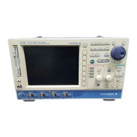
YOKOGAWA DL7480 User Manual (55 pages)
Digital Oscilloscope Power Supply Analysis Function G4 Option
Brand:
YOKOGAWA
| Category:
Test Equipment
| Size: 0.54 MB
Table of Contents
How to Use this Manual
3
Table of Contents
4
Overview of the Power Analysis Function
5
Connecting Probes/Performing Phase Correction, Degauss, and Zero Adjustment/Deskewing
7
Turning on the Power Analysis Function/Selecting the Attenuation or Current-To-Voltage Conversion Ratio of Probes/Enabling Waveform Computation Setup
8
Correcting (Deskewing) the Difference in the Transfer Time of Analyzed Signals
11
Performing Automated Measurement of Power Analysis Parameters
14
Performing Statistical Processing on the Measured Values of Power Analysis Parameters
18
Performing Waveform Computation on Power Analysis Parameters
19
Displaying the Trend of the Measured Values of Waveform Parameters Per Cycle
27
Performing History Search Using Measured Values of Power Analysis Parameters
30
Performing GO/NO-GO Determination Using Measured Values of Power Analysis Parameters
33
Saving the Computed Results of Harmonics
34
Communication Commands
36
Messages and Corrective Actions
49
Specifications
50
Appendix 1 Setup Parameters that Are Changed During the Execution of Auto Deskew
51
Appendix 2 Record Length and T/DIV Settings that Allow Waveform Computation of Harmonics
52
Index
53
Advertisement
YOKOGAWA DL7480 Operation Manual (29 pages)
Digital Oscilloscope
Brand:
YOKOGAWA
| Category:
Test Equipment
| Size: 0.85 MB
Table of Contents
Foreword
2
Table of Contents
3
Flow of Operation
4
Names and Functions of Front Panel Controls
5
Parts of the Screen
8
Basic Key and Jog Shuttle Operation
11
Introduction to Main Functions
13
Cursor Measurements
15
Working with the DL7400
18
Preparing for an Observation
18
Connecting the Probe
19
Displaying a Waveform on the Screen
20
Changing Waveform Display Conditions
21
Changing Trigger Settings
24
Measuring a Waveform
26
Zooming a Waveform Along the Time Axis
27
Printing and Saving a Waveform
28
Advertisement
Related Products
YOKOGAWA DL716
YOKOGAWA DL7440
YOKOGAWA DL7200
YOKOGAWA DL7400
YOKOGAWA DL 1540
YOKOGAWA DL 1520
YOKOGAWA DL9240L
YOKOGAWA DL9000 Series
YOKOGAWA DL1640
YOKOGAWA DL1640L
YOKOGAWA Categories
Measuring Instruments
Test Equipment
Transmitter
Controller
Media Converter
More YOKOGAWA Manuals
Login
Sign In
OR
Sign in with Facebook
Sign in with Google
Upload manual
Upload from disk
Upload from URL