Sign In
Upload
Manuals
Brands
Riso Manuals
Printer
Comcolor X1 Series
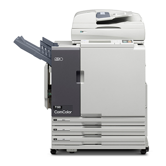
Riso Comcolor X1 Series Manuals
Manuals and User Guides for Riso Comcolor X1 Series. We have
4
Riso Comcolor X1 Series manuals available for free PDF download: Technical Manual, Getting Started Manual, Quick Manual
Riso Comcolor X1 Series Technical Manual (909 pages)
Brand:
Riso
| Category:
Printer
| Size: 43 MB
Table of Contents
Chapter 2. Machine Covers
21
Handling of Lithium Battery ]
2
Precautions
5
Other Precautions for Inspection and Maintenance
7
Sensors
8
Tools
9
List of Special Tools for Servicing Comcolor
10
Printer Setup Procedure
15
Setup Wizard
16
Table of Contents
21
Exterior Covers
22
Removal
23
2-1.Operation Panel as a Unit
23
2-2.Front Bottom Cover
23
2-3.Front Doors
24
Comcolor Series (Revision
24
2-4.Rear Cover
25
2-5.Front Door Lock Mechanism
26
2-6.Opening the Pcbs and Ink Supply Unit to the Service Mode
27
2-7.Component Layout (Rear of the Machine)
29
Chapter 3. Structural Overview
31
Comcolor Series Specifications
32
HS4000 Scanner Specifications
39
Multifunction Finisher Specifications
41
IC Card Authentication Kit Specifications
43
Structural Overview
45
Overall Block Structure
45
Overview of Paper Transfer
49
Overview of Ink Flow Path
51
Ink Supply Unit
52
Chapter 4. External Paper Feed Section
55
Mechanisms
56
Basic Structure
56
Paper Feed Tray Elevation Mechanism
59
Paper Feed Mechanism
61
Paper Size Detection Mechanism
63
Paper Volume Detection Mechanism
64
Multiple Paper Feed Detection Mechanism
65
Noise Reduction Paper Feed Assisting Action
66
Disassembly
67
Elevator Motor
67
Paper Feed Tray Unit
68
Paper Feed Tray Paper Detection Sensor
69
Paper Feed Tray Paper Width Potentiometer
69
Paper Feed Tray Paper Length Detection Sensor
70
Paper Feed Tray Paper Volume Detection Sensors 1 and
70
Paper Feed Tray Lower Limit Sensor
70
External Paper Feed Motor Assembly
71
External Paper Feed Unit
71
Stripper Interlock Switch
74
Paper Feed Tray Upper Limit Sensors a and B
75
Paper Feed Tray Upper Safety Switch
75
Paper Feed Tray Elevation Switch
76
Paper Feed Tray Lower Safety Switch
76
Pickup Roller
77
Scraper Roller
77
Stripper Plate
77
Adjustment
79
Upper Limit Position Adjustment
79
Adjusting the Paper Width Potentiometer
80
Adjusting the External Paper Feed Amount
80
Chapter 5. Internal Paper Feed
81
Mechanisms
82
Basic Structure
82
Internal Paper Feed Action
83
Paper Feed Tray Unit
83
Internal Paper Feed Unit
84
Paper Volume Detection Mechanism
85
Paper Size Detection Mechanism
86
Assist Action
87
Paper Transfer Action
88
Disassembly
95
Internal Paper Feed Unit (Tray 1)
95
Internal Paper Feed Unit (Tray 2)
97
Internal Paper Feed Unit (Tray 3)
98
Internal Paper Feed Motor
99
Internal Paper Feed Clutches 1, 2 and 3
100
Upper Limit Sensors of Trays 1, 2 And/Or 3
100
Paper Detection Sensors of Trays 1 to 3 (3 Sets)
101
Stripper Plates 1, 2 or 3
101
Internal Paper Feed Rollers 1, 2 And/Or
102
Elevator Motors for Trays 1, 2 and 3
103
Set Interlock Switch for Trays 1, 2 and 3
104
Paper Volume Detection Sensor for Trays 1, 2 and 3
104
Adjustment
107
Stripper Plate Angle Adjustment
107
Internal Paper Feed Upper Limit Position Adjustment
107
Position Adjustment
108
Chapter 6. Registration Section
111
Mechanisms
112
Basic Structure
112
Vertical Paper Feed Unit B Mechanism
113
Vertical Paper Feed Unit a Mechanism
114
Assist Action
116
Registration Roller Mechanism
117
Paper Position Detection Unit Mechanism
118
Detection Mechanism for Leading and Trailing Edges
120
Disassembly
121
Vertical Paper Feed Unit a
121
Vertical Paper Feed Sensor 5 (Vertical Paper Feed Unit A)
122
Vertical Paper Feed Roller 5 (Vertical Paper Feed Unit A)
122
Vertical Paper Feed Unit B
123
Vertical Paper Feed Sensor 1 (Vertical Paper Feed Unit B)
124
Vertical Paper Feed Sensor 2 (Vertical Paper Feed Unit B)
124
Vertical Paper Feed Sensor 3 (Vertical Paper Feed Unit B)
124
Vertical Paper Feed Sensor 4 (Vertical Paper Feed Unit B)
124
Vertical Paper Feed Roller 1 (Vertical Paper Feed Unit B)
125
Vertical Paper Feed Roller 2 (Vertical Paper Feed Unit B)
125
Vertical Paper Feed Roller 3 (Vertical Paper Feed Unit B)
125
Vertical Paper Feed Roller 4 (Vertical Paper Feed Unit B)
125
Internal Feed Paper Jam Door Interlock Switch
126
Vertical Paper Feed Clutch 1
126
Vertical Paper Feed Clutch 2
126
Registration Motor Assembly
127
Registration Sensor (Send)
128
Registration Sensor (Receive)
128
Top Edge Sensor 1 (Send)
129
Top Edge Sensor 1 (Receive)
129
Registration Roller
129
Guide Roller
131
Rear View
131
Front View
131
Paper Position Detection Unit
132
Paper Lift Detection Sensor
133
Paper Width Detection Sensor (FRONT & REAR)
133
Adjustment
135
Adjustment to Make the Registration Roller and BP Unit Parallel
135
CIS Adjustment
135
Sensor Sensitivity Adjustment
139
Chapter 7. Bp Section
143
Mechanisms
144
Raising and Lowering of the Belt Platen
145
Paper Transfer Mechanism
146
Head Gap Adjustment Action
146
Paper Suction Action
147
Ink Drop Position Adjustment
148
Drive Roller
148
BP Contact Detection Mechanism
149
Gap Adjuster Mechanism
150
BP Wire Loose Detection Mechanism
152
Disassembly
153
Removing the BP Unit
153
Transfer Belt Motor Assembly
155
Belt HP Sensor
155
BP Upper Limit Sensor
156
BP Lower Limit Sensor
156
Belt Shaft FG Sensor Assembly (Encoder)
157
Transfer Belt
157
Transfer Belt Suction Fans (6)
160
BP Lift Wires
161
Adjustment
163
Ink Drop Position Enhancement Adjustment
163
Transfer Belt Alignment
166
Adjustment to Make the BP Unit
169
Chapter 8. Paper Transfer Section
171
Mechanisms
172
Basic Structure
172
Paper Elevation Unit Mechanism
172
Upper Transfer Unit Mechanism
173
Face up Paper Ejection (Optional)
174
Disassembly
175
Paper Elevation Motor
175
Paper Elevation Unit
175
Paper Elevation in Sensor (Paper Elevation Unit)
176
Upper Transfer Roller 1 (Paper Elevation Unit)
176
Upper Transfer Roller 2 (Paper Elevation Unit)
176
Driven Roller (Paper Elevation Unit)
177
Upper Transfer Motor
177
Flipper Sensor
178
Upper Transfer Unit
178
Upper Transfer Roller 3 (Upper Transfer Unit)
179
Upper Transfer Roller 4 (Upper Transfer Unit)
179
Upper Transfer Roller 5 (Upper Transfer Unit)
179
Chapter 9. Paper Ejection Section
181
Mechanisms
182
Basic Structure
182
FD Paper Ejection Unit
184
Switching the Paper Ejection Path
184
Paper Receiving FULL Detection Mechanism
187
FD Fence Unit
188
Paper Receiving Tray Unit (Optional)
189
Disassembly
191
Removing the Unit
191
FD Paper Ejection Fence Motor (FD Fence Unit)
193
FD Paper Ejection Fence HP Sensor (FD Fence Unit)
193
FD Paper Ejection Full Detection Sensor
194
FD Paper Ejection Motor (FD Paper Ejection Unit)
194
FD Paper Ejection Motor FG Sensor (FD Paper Ejection Unit)
194
FD Paper Ejection Flipper Solenoid (FD Paper Ejection Unit)
195
FD Paper Ejection Sensor (FD Paper Ejection Unit)
195
FD Ejection Roller (FD Paper Ejection Unit)
195
FD Ejection Driven Roller (FD Paper Ejection Unit)
196
FD Paper Ejection Paper Detection Sensor
196
FD Paper Ejection Unit
197
Adjustment
197
FD Paper Ejection Flipper Solenoid (FD Paper Ejection Unit)
197
Phase Adjustment of the Fence Rack (FD Fence Unit)
198
Chapter 10. Switchback Section
199
Mechanisms
200
Basic Structure
200
Mechanisms of Switchback Units a and B
200
Noise Reduction Paper Feed Assisting Action
204
Disassembly
205
Switchback Motor
205
Re-Feed Motor
205
Switchback Unit a
206
Switchback Unit B
208
Switchback Door Interlock Switch (Switchback Unit A)
209
Switchback Sensor (Switchback Unit A)
209
Re-Feed Sensor (Switchback Unit A)
210
Re-Feed Roller (Switchback Unit A)
210
Switchback Roller (Switchback Unit A)
210
Upper Transfer out Sensor (Switchback Unit B)
211
Upper Transfer Roller 6 (Switchback Unit B)
211
Chapter 11A. Ink Flow Section
213
Mechanisms
214
Ink Supply Mechanisms
214
Ink Path Diagram
215
Ink Circulation Unit Structure
216
Standard Action of Ink Supply Mechanisms
223
Disassembly
227
Cutting the Ink Tubes
227
Ink Spill Prevention from the Ink Cartridge Holder Unit
229
Removing the Scissor Clamps
232
Bellows Unit
233
Initial Ink Filling
241
Removing the Head Holder Cover
243
Ink Cartridge
246
Ink Cartridge Holder Unit
246
Cartridge Holder Joint Drive Motor
250
Ink Cartridge RFID PCB
251
Ink Supply Valve
252
Negative Pressure Ink Tank
255
Print Head
279
Cooling Fan
296
Image Adjustment
319
Chapter 12. Waste Ink Section
320
Mechanisms
321
Head Maintenance Mechanism
321
Waste Ink Detection Mechanism
323
Disassembly
326
Maintenance Unit
326
Maintenance Unit Slide Motor
331
Maintenance Unit Wiper and Wiper Motor
332
Wiper HP Sensor
333
Operation Position Sensor
333
Storage Position Sensor
334
Waste Ink Tank Sensor
334
Waste Ink Tank & Waste Ink Tank Holder
335
Chapter 13. Gdi Controller
338
Main Functions
340
Built-In Controller (GDI)
341
Connecting a Computer
341
Printer Network Settings
342
Compatible Computers (Operating Systems)
344
Supported Protocols
344
Printer Driver Installation
346
Installing the Printer Driver (Windows 7 - RAW Port)
346
Installing the Printer Driver (Windows 7 - LPR/IPP Port)
350
Chapter 14. Electronic Components
352
Overall Structure of Boards
353
Board Wiring
353
Board Confi Guration
354
Electronic Components
354
Board Components
355
Power Supply PCB
355
Engine Control PCB
358
Controller PCB (Including Recording Data Generating PCB)
362
Option PCB
367
Other Boards
368
Interlock Circuit
371
Electronic Parts Search Table
372
Electronic Parts Structural Figure
376
Unit Front View
376
External Paper Feed & Registration
378
Internal Paper Feed (with Trays)
379
BP Unit
381
BP Elevation
382
Paper Transfer
383
FD Paper Ejection
384
Switchback
385
Ink Supply
386
Ink Cartridge Holder
388
Print Heads
389
Waste Ink Tank
391
Block Diagrams & Wiring Diagrams
392
Overall Block Diagram 1
392
Overall Block Diagram 2
393
Power Supply Unit
410
Recording Data Generating PCB (X3-IP-PCB)
410
Downloading Firmware Data
410
Various Options
410
PCB Replacements
413
Chapter 15. Panel Messages
432
Error Code Display
433
Error Type
434
Error Point
436
Variation Code
436
Comcolor Paper Jams
437
Reason for Jams
437
Position of Paper Still in Printer
437
Requirements to Clear Jams, with Respect to Positions of Paper Still in Printer
438
Service Call
439
Service Call Errors (S)
443
Warnings (W)
483
Jam Errors (X)
513
Supply Errors (Y)
522
Error Code Point
531
Requirements to Clear Jams in Finisher
538
Requirements to Clear Jams in Various Options
539
Requirements to Clear Jams in Offset Stapler
539
Requirements to Clear Jams in High Capacity Feeder
539
Chapter 16. Test Modes
544
Entering into Test Mode
545
Mode Screen
545
Keypad Operation to Enter into Test Mode
545
Exiting out of Test Mode
546
Test Mode Numbering System
547
Meaning of the Numbers for each Test Mode Digit
547
Example Test Modes
548
Executing Test Modes
549
Entering Test Mode Numbers
549
Sensor Monitoring (S)
553
Drive Checking (M)
557
Unit Checking (U)
563
Sensor Monitoring (S)
603
Drive Checking (M)
605
Drive Checking (M)
606
Chapter 19. Face down Offset Stapler
688
Brief Summary
690
Major Functions
690
Specification
691
Major Components
692
Periodic Replacement Parts
693
Mechanism
694
Paper Transfer
694
Summary of each Paper Path
694
Non-Offset Paper Ejection
694
Offset Paper Ejection
695
Initialization Movement
698
Action before Job Starts
698
Paper Receive Ready Position Movement
699
Paper Stacking Tray Paper Top Surface Position
699
Paper Top Surface Detecting Mechanism
699
Paper Stacking Tray Paper Surface Position Detecting Action
701
Disassembly
724
Detaching of the Face down Offset Stapler from the Printer
724
Front Cover Removal
724
Rear Cover Removal
725
Face down Offset Stapler
726
Power Supply Unit Removal
736
Eject Roller (Drive Side) Removal
746
Reverse Roller Removal
748
Transfer Sensor 1 Removal
749
Entrance Sensor Removal
750
Staple Tray Paper Detection Sensor
751
Switchback Pass Sensor Removal
752
Eject Roller Elevation HP Sensor Removal
753
Rake Roller Elevation HP Sensor Removal
753
Paper Stacking Tray Upper Limit Sensor Removal
754
Paper Stacking Tray Elevation Clock Sensor Removal
754
Paper Stacking Tray Lower Limit Sensor Removal
755
Tray Shift Clock Sensor Removal
755
Tray Shift Sensor 1 & Tray Shift Sensor 2 Removal
756
Stapler Slide HP Sensor Removal
757
Reverse Roller Elevation HP Sensor Removal
758
Stacking Tray Paper Detection Sensor Removal
759
Front Tamper HP Sensor & Rear Tamper HP Sensor Removal
760
Tray Paper Top Detection Sensors 1, 2 and 3 Removal
761
Tray Paper Top Detection Sensor 2 Removal
761
Staple Scratch Protection Arm HP Sensor Removal
762
Stapler Base Position Sensor Removal
762
Stapler Slide Motor Removal
763
Eject Roller Elevation Motor Removal
764
Rake Roller Elevation Solenoid
764
Transfer Roller Motor 1 Removal
765
Transport Motor Removal
767
Ejection Motor Removal
768
Tray Elevation Motor Removal
770
Cooling Fan Removal
771
Tray Shift Motor Removal
772
Staple Scratch Protection Arm Motor
773
Reverse Roller Motor
774
Reverse Roller Elevation Motor Removal
774
Front Tamper Motor & Rear Tamper Motor Removal
775
Stapler Cable Removal
776
Other Removals
779
Control Board (PCB) Replacement
779
Chapter 20. Hs5000 Scanner (Option)
780
Specification
782
FB Unit
783
Original Set Section
783
Original Scanning
784
Functional Positions of the Scanner
785
AF Unit
787
Original Set Section
787
Setting the Original
787
Original Size Detection
787
Original Path
788
Roller Rotation
789
Separation Roller
790
Periodic Replacement Parts
791
Disassembly
792
FB Unit
792
Disassembly
806
AF & FB Firmware Downloading
814
CS5-MAIN-PCB Replacement
814
Adjustment
814
Other Adjustments
814
Electrical Parts and Related Test Modes
815
Chapter 24. Multifunction Finisher II (Option)
816
Overview
817
Structure of Multifunction Finisher
817
Overview of Functions
818
Overall Structure
824
Printed Wiring Boards and Set Switches
828
Procedure for Replacing Finisher PWB
830
Replacement Procedure
830
Power Supply System
831
Cautions Regarding Disassembly and Reassembly
832
Removal of Covers
834
Removal of Units
836
I/F Module
842
Basic Mechanism
842
Disassembly
848
Puncher Section and Stapler Section
854
Basic Mechanism of Puncher Section
854
Basic Mechanism of Top Tray
857
Basic Mechanism of Compile Section
859
Disassembly
866
Stacker Tray Section
878
Basic Mechanism
878
Disassembly
881
Booklet Section
884
Basic Mechanism
884
Disassembly
888
Adjustment
898
Staple and Fold Position Adjustments in the Booklet Section
898
Staple Position Adjustment
906
Advertisement
Riso Comcolor X1 Series Getting Started Manual (20 pages)
Brand:
Riso
| Category:
Printer
| Size: 0 MB
Riso Comcolor X1 Series Getting Started Manual (8 pages)
Brand:
Riso
| Category:
Printer
| Size: 0 MB
Table of Contents
Scanning Images to Email
4
Scanning Jobs to a Computer
5
Scanning Images to a USB Flash Drive
6
Scanning Jobs to Internal Hard Disk
7
Advertisement
Riso Comcolor X1 Series Quick Manual (2 pages)
Brand:
Riso
| Category:
Printer
| Size: 0 MB
Advertisement
Related Products
Riso Comcolor Series
Riso ComColor FW Series
Riso ComColor black FW Series
Riso ComColor FT Series
Riso ComColor Black FT Series
Riso ComColor GL Series
Riso ComColor black FT Series
Riso comcolor gd series
Riso 3010
Riso 3010R
Riso Categories
Printer
All in One Printer
Disc Duplicator
Printer Accessories
Copier
More Riso Manuals
Login
Sign In
OR
Sign in with Facebook
Sign in with Google
Upload manual
Upload from disk
Upload from URL